Experimental Investigation on Heat Transfer Mechanism of Air-Blast-Spray-Cooling System with a Two-Phase Ejector Loop for Aeronautical Application


Abstract
:1. Introduction
2. Concept Design and Experimental Set-Up of ABSCS for Aeronautical Application
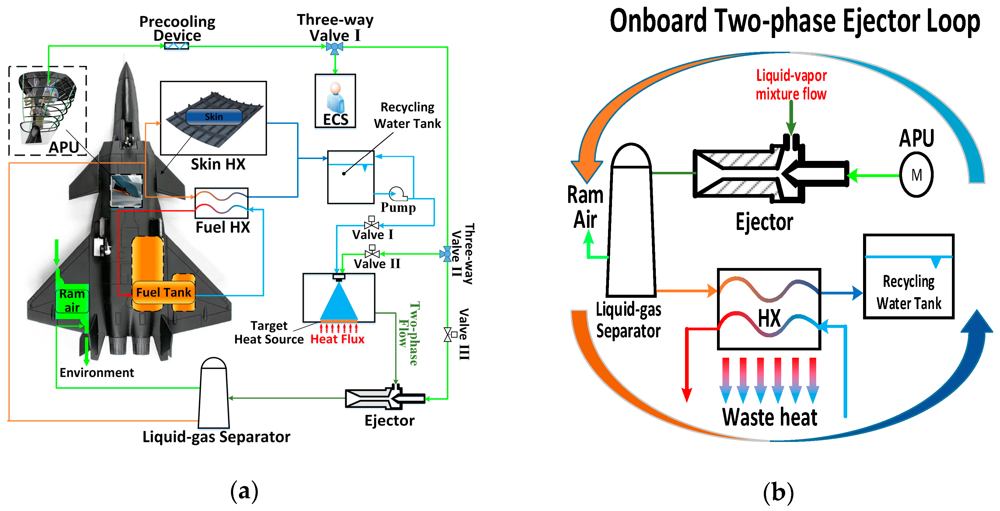
2.1. Mechanism of the Onboard ABSCS
2.2. Ground-Based ABSCS
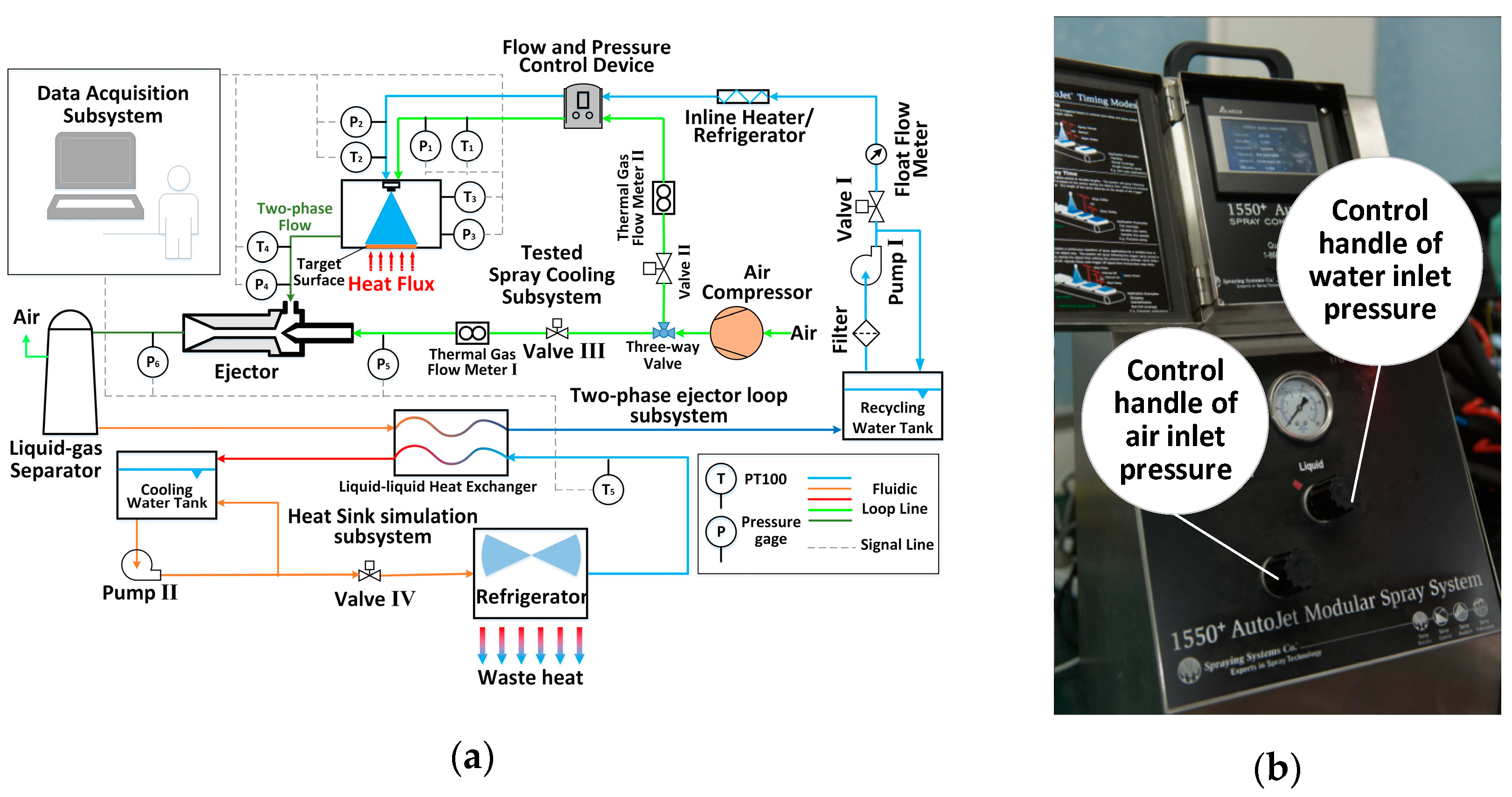
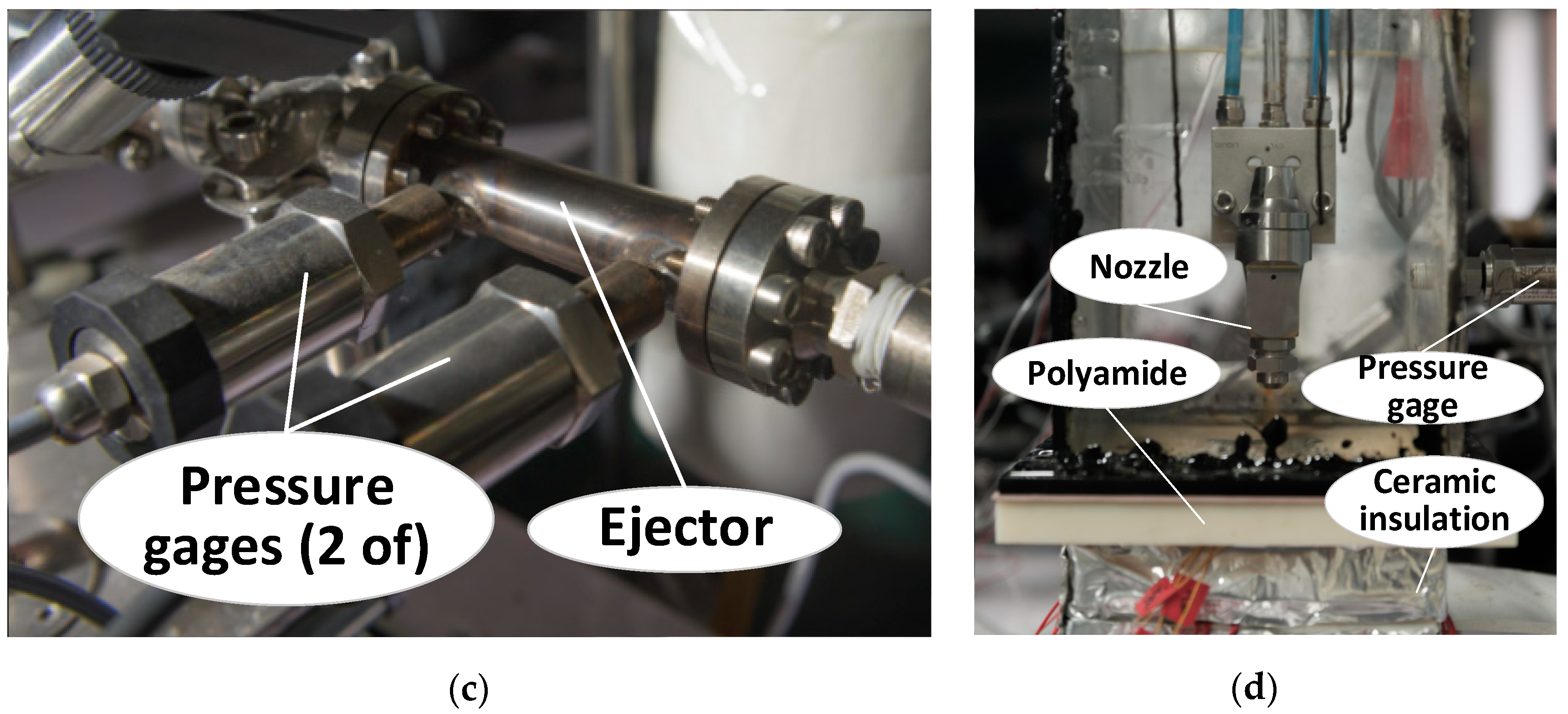
2.2.1. Experimental Set-Up
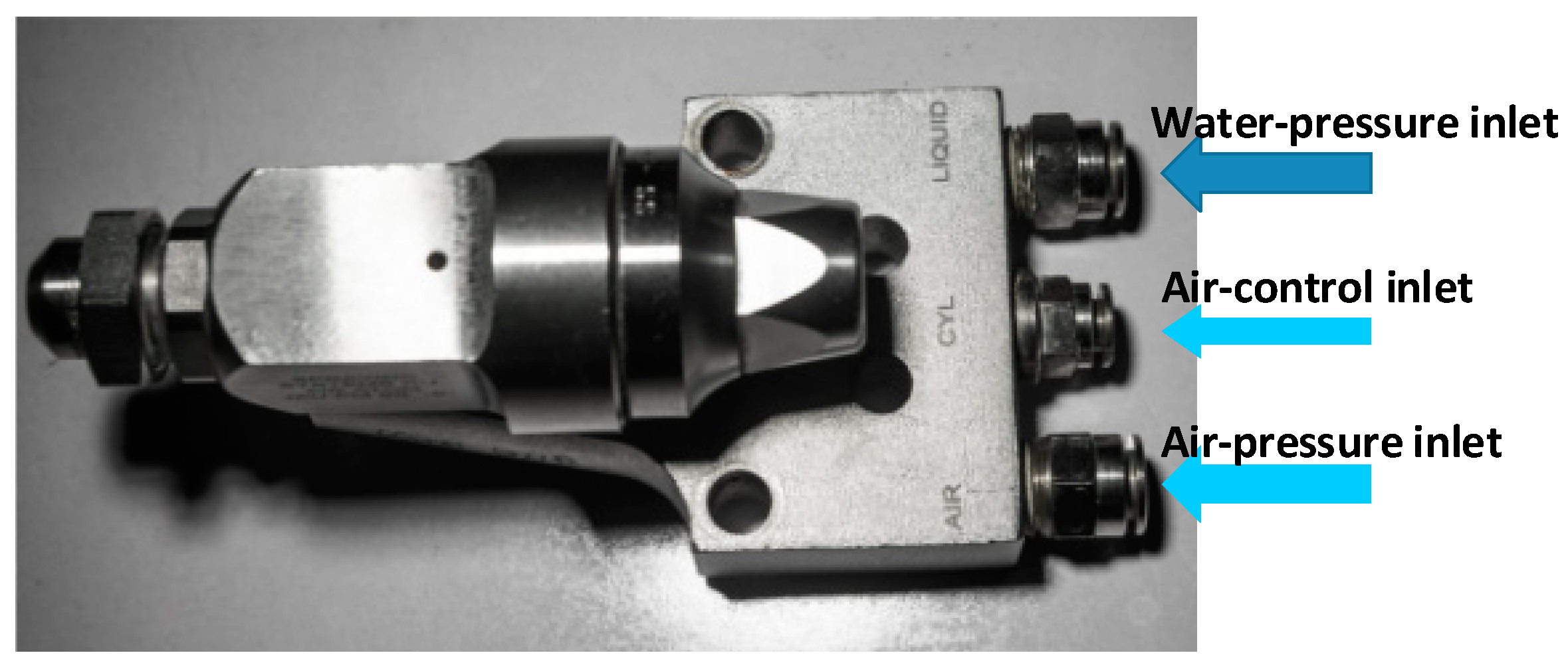
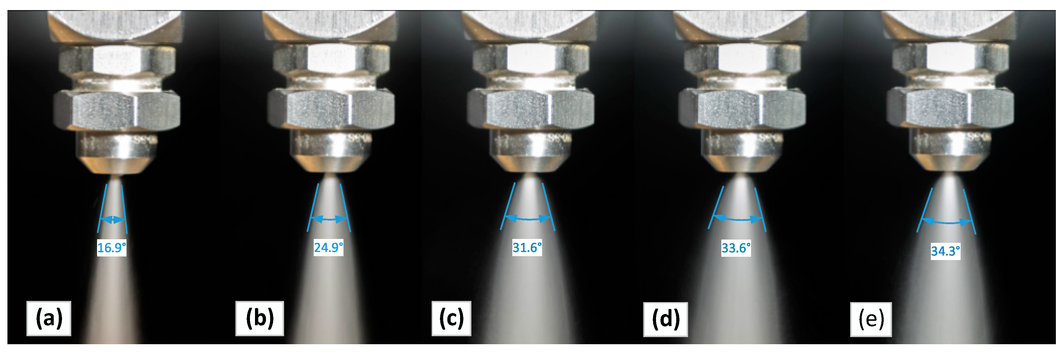
2.2.2. ABAN in Spray Chamber
2.2.3. Simulated Heat Source
2.3. Operating Condition Arrangement and Experimental Procedure
3. Experimental Results and Discussions
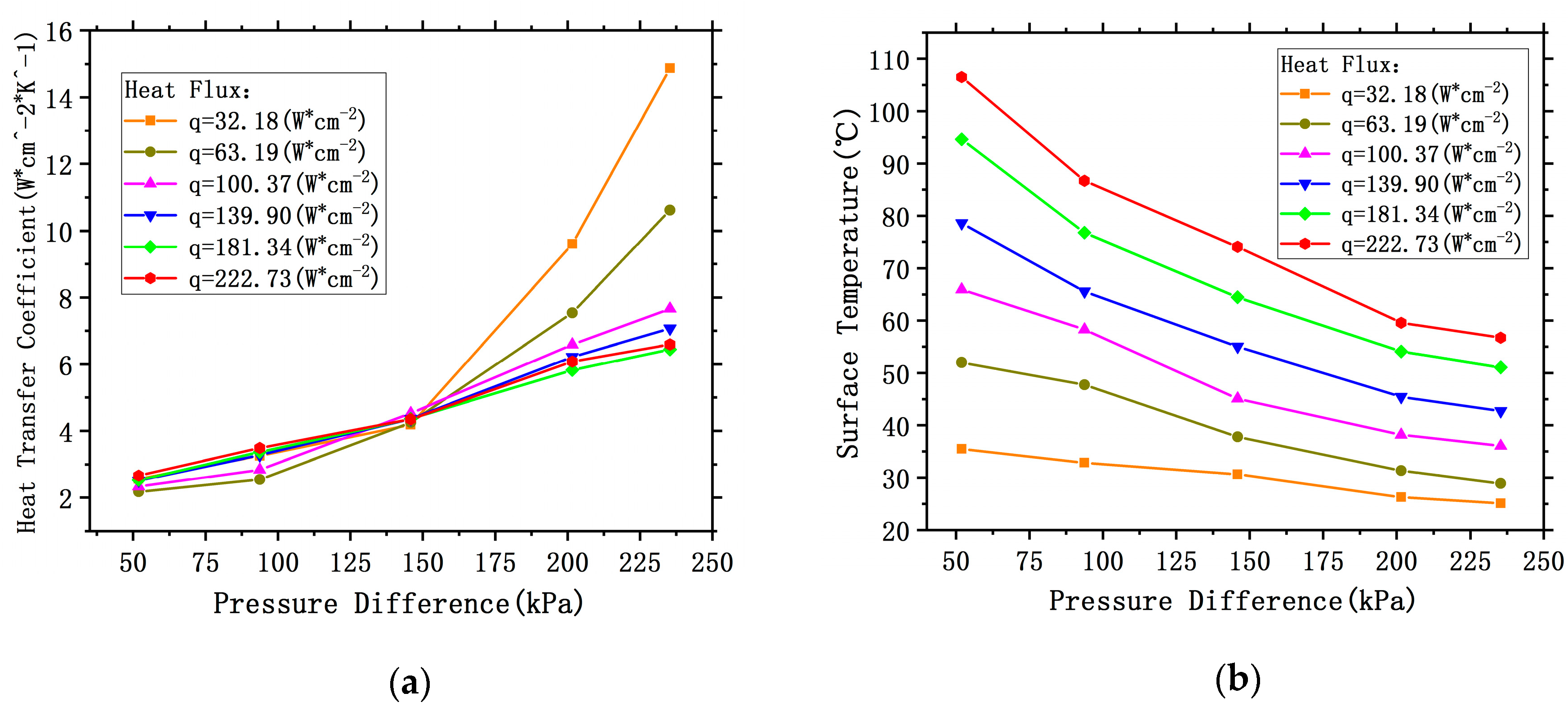
3.1. Effects of PDWIC
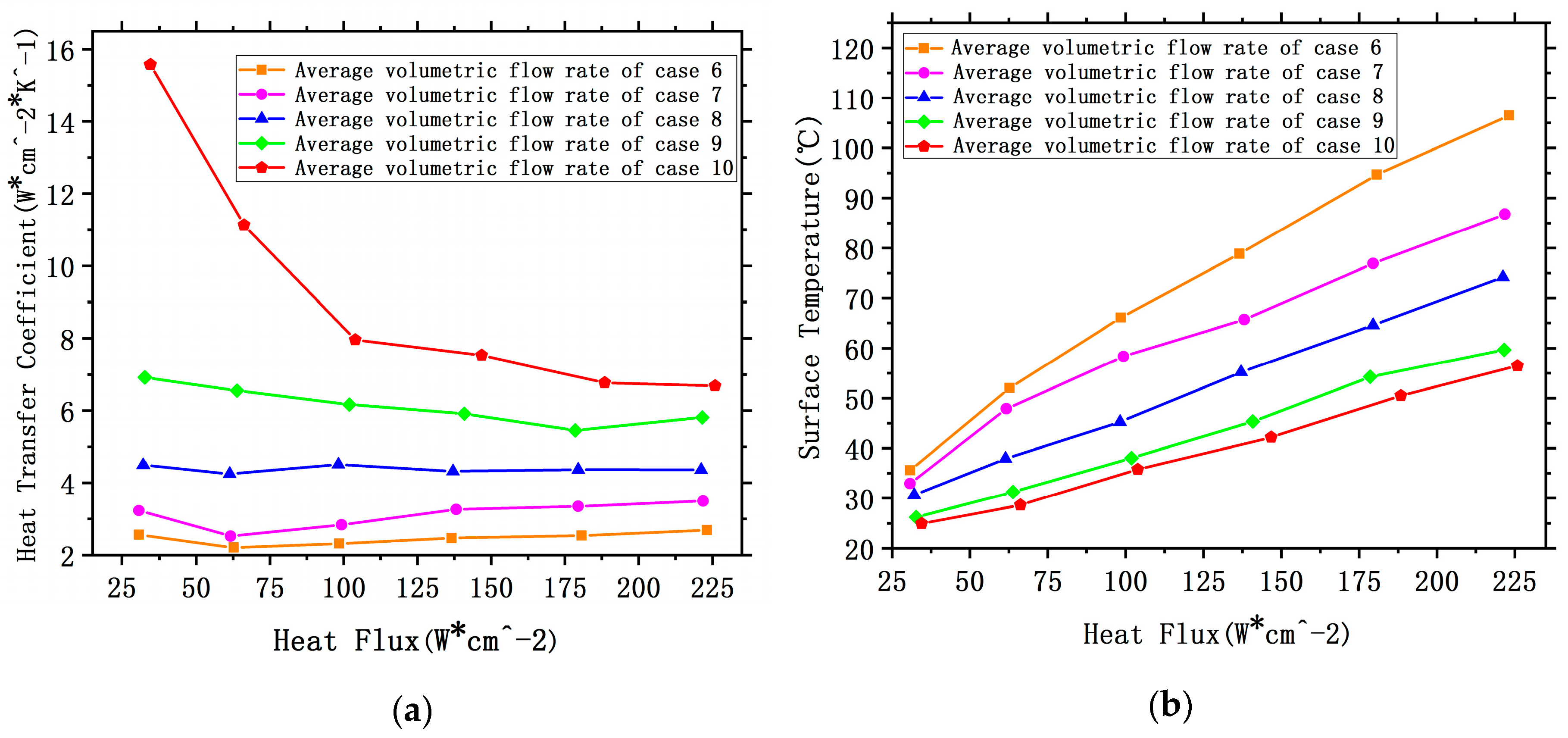
3.2. Effects of SVFR
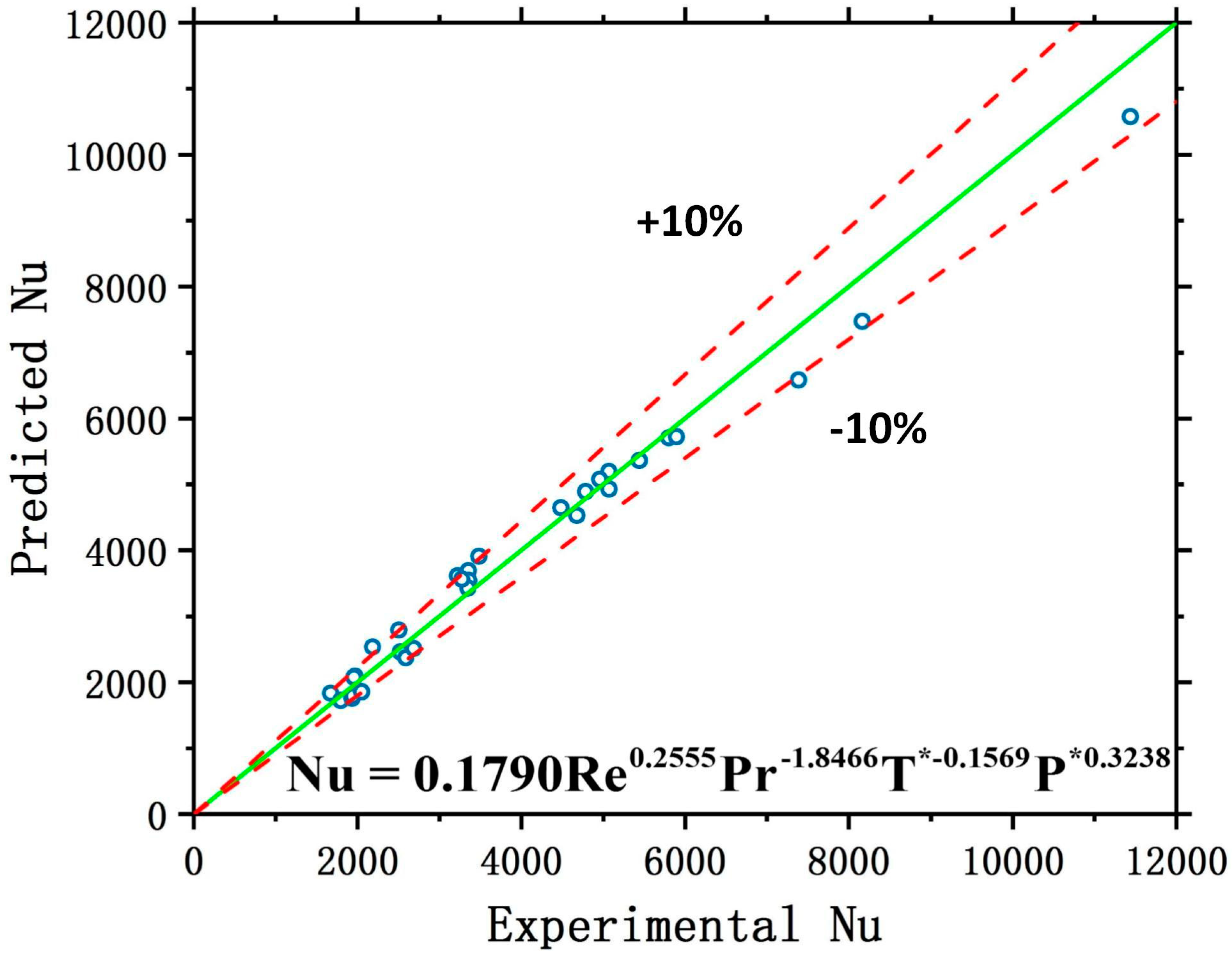
3.3. Experimental Dimensionless Correlation
4. Conclusions and Future
- Both PDWIC and SVFR are critical factors affecting the heat transfer performance of ABSCS. Under a constant operating condition, the cooling capacity can be promoted by a greater PDWIC or a higher SVFR respectively.
- Under the same heating power, the heat dissipation capacity of spray cooling is proportional to the two dimensionless parameters Reynolds number Re and Weber number We due to the variation of droplet-impacting velocity and droplet size as the change of PDWIC or SVFR.
- Compared with the factor of the droplet size, the spray cooling performance is more sensitive to the variation in the droplet-impacting velocity.
Author Contributions
Funding
Acknowledgments
Conflicts of Interest
Nomenclature
| T | Temperature (°C) | low | location of low |
| Average temperature (°C) | i | location of i (i = 1, 2, 3) | |
| Dimensionless temperature | sur | target surface | |
| q | Heat flux (W·cm−2) | in | inlet |
| Length (m) | env | environment | |
| Velocity (m·s−1) | sat | Saturation condition | |
| Pressure (Pa) | cu | oxygen-free copper block | |
| Dimensionless of pressure | s-up | Target surface—location up | |
| h | Heat transfer coefficient (W·m−2·K−1) | s-low | Target surface—location low |
| Diameter (m) | dro | droplet | |
| Sauter mean diameter (c) | water-in | Water inlet | |
| D | characteristic length (m) | air-in | Air inlet |
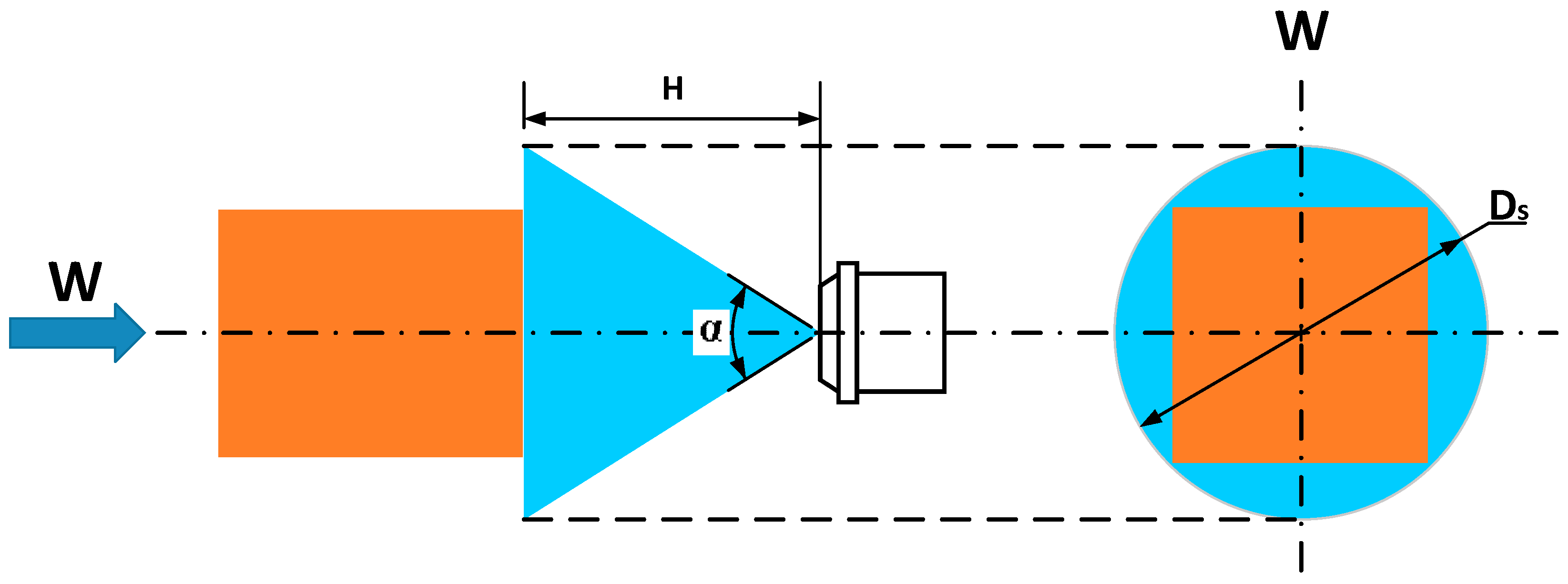
| Ds | Projection diameter of spray on the target surface (m) | cavity | Spray cavity |
| A | Area (m2) | diff | Pressure difference |
| C | Perimeter (m) | y | Parameter substitution symbol |
| R | Gas constant (8314 ) | Acronyms | |
| M | Molar mass (g/mol) | SCS | Spray Cooling System |
| H | Height (m) | HTP | Heat Transfer Performance |
| cp | Specific heat at constant pressure () | AIP | Air-Inlet-Pressure |
| Gm | Spray mass flow rate () | WIP | Water-Inlet-Pressure |
| z | The fitting coefficient | PDWIC | Water-Inlet-Pressure and the Spray Cavity one |
| Re | Reynolds number | SVER | Spray Volumetric Flow Rate |
| We | Weber number | ABAN | Air-Blast Atomization Nozzle |
| Kn | Knudsen number | SMD | Sauter Mean Diameter |
| Pr | Prandtl number | GLR | Gas-to-Liquid Ratio |
| Nu | Nusselt number | APU | Auxiliary Power Unit |
| x | Parameter substitution symbol | DAS | Data Acquisition Subsystem |
| Greek symbols | TSCS | Tested Spray Cooling Subsystem | |
| Thermal conductivity () | ASTM | American Society of Testing Materials | |
| Uncertainty (%) | TELS | Two-phase Ejector Loop Subsystem | |
| Density () | FPCD | Flow and Pressure Control Device | |
| Surface tension () | TMS | Thermal Management System | |
| the mean free path of the molecule | PD | Pressure Difference | |
| Dynamic viscosity () | EP | Environment Pressure | |
| Spray angle (o) | ABSCS | Air-Blast-Spray-Cooling System | |
| Subscripts | PDWIPSC | Pressure Difference between Water-Inlet-Pressure and the Spray Cavity one | |
| up | location of up | HX | Heat exchanger |
Appendix A
Uncertainty Analysis
References
- Murshed, S.M.S.; De Castro, C.A.N. A critical review of traditional and emerging techniques and fluids for electronics cooling. Renew. Sustain. Energy Rev. 2017, 78, 821–833. [Google Scholar] [CrossRef]
- Wang, J.X.; Li, Y.Z.; Zhang, Y.; Li, J.X.; Mao, Y.F.; Ning, X.W. A hybrid cooling system combining self-adaptive single-phase mechanically pumped fluid loop and gravity-immune two-phase spray module. Energy Convers. Manag. 2018, 176, 194–208. [Google Scholar] [CrossRef]
- O’Keefe, M.; Bennion, K. A comparison of hybrid electric vehicle power electronics cooling options. In Proceedings of the 2007 IEEE Vehicle Power and Propulsion Conference, Arlington, VA, USA, 9–12 September 2007; IEEE: Piscataway, NJ, USA, 2007; pp. 116–123. [Google Scholar]
- Liping, P.; Kun, L.; Qi, G.; Shuxin, L.; Chao, Y. Numerical study of high-overload effect on liquid film of spray cooling. Appl. Therm. Eng. 2017, 127, 1015–1024. [Google Scholar] [CrossRef]
- Elston, L.J.; Yerkes, K.L.; Thomas, S.K.; McQuillen, J. Cooling performance of a 16-nozzle array in variable gravity. J. Thermophys. Heat Transf. 2009, 23, 571–581. [Google Scholar] [CrossRef]
- Pais, M.R.; Chow, L.C.; Mahefkey, E.T. Surface roughness and its effects on the heat transfer mechanism in spray cooling. J. Heat Transf. 1992, 114, 211–219. [Google Scholar] [CrossRef]
- Wang, J.X.; Li, Y.Z.; Li, J.X.; Li, C.; Zhang, Y.; Ning, X.W. A gas-atomized spray cooling system integrated with an ejector loop: Ejector modeling and thermal performance analysis. Energy Convers. Manag. 2019, 180, 106–118. [Google Scholar] [CrossRef]
- Cheng, W.L.; Zhang, W.W.; Chen, H.; Hu, L. Spray cooling and flash evaporation cooling: The current development and application. Renew. Sustain. Energy Rev. 2016, 55, 614–628. [Google Scholar] [CrossRef]
- Cader, T.; Westra, L.J.; Eden, R.C. Spray cooling thermal management for increased device reliability. IEEE Trans. Device Mater. Reliab. 2005, 4, 605–613. [Google Scholar] [CrossRef]
- Bancoff, S.G. Stability and dynamics of thin heated liquid films. Int. J. Fluid Mech. Res. 1998, 25, 189–201. [Google Scholar] [CrossRef]
- Yang, B.H.; Wang, H.; Zhu, X.; Liao, Q.; Ding, Y.D.; Chen, R. Heat transfer enhancement of spray cooling with ammonia by microcavity surfaces. Appl. Therm. Eng. 2013, 50, 245–250. [Google Scholar] [CrossRef]
- Lin, L.; Ponnappan, R. Heat transfer characteristics of spray cooling in a closed loop. Int. J. Heat Mass Transf. 2003, 46, 3737–3746. [Google Scholar] [CrossRef]
- Hsieh, C.C.; Yao, S.C. Evaporative heat transfer characteristics of a water spray on micro-structured silicon surfaces. Int. J. Heat Mass Transf. 2006, 49, 962–974. [Google Scholar] [CrossRef]
- Ashwood, A.C.; Shedd, T.A. Spray cooling with mixtures of dielectric fluids. In Proceedings of the Twenty-Third Annual IEEE Semiconductor Thermal Measurement and Management Symposium, San Jose, CA, USA, 18–22 March 2007; IEEE: Piscataway, NJ, USA, 2007; pp. 144–148. [Google Scholar]
- Silk, E.A.; Kim, J.; Kiger, K. Spray cooling of enhanced surfaces: Impact of structured surface geometry and spray axis inclination. Int. J. Heat Mass Transf. 2006, 49, 4910–4920. [Google Scholar] [CrossRef]
- Monde, M. Critical heat flux in the saturated forced convection boiling on a heated disk with impinging droplets. Trans. JSME 1979, 8, 54–64. [Google Scholar]
- Wang, J.X.; Li, Y.Z.; Li, G.C.; Xiong, K.; Ning, X. Investigation of a gravity-immune chip-level spray cooling for thermal protection of laser-based wireless power transmission system. Int. J. Heat Mass Transf. 2017, 114, 715–726. [Google Scholar] [CrossRef]
- Pavlova, A.A.; Otani, K.; Amitay, M. Active performance enhancement of spray cooling. Int. J. Heat Fluid Flow 2008, 29, 262–277. [Google Scholar] [CrossRef]
- Hsieh, S.S.; Fan, T.C.; Tsai, H.H. Spray cooling characteristics of water and R-134a. Part II: Transient cooling. Int. J. Heat Mass Transf. 2004, 47, 5713–5724. [Google Scholar] [CrossRef]
- Zhou, N.; Chen, F.; Cao, Y.; Chen, M.; Wang, Y. Experimental investigation on the performance of a water spray cooling system. Appl. Therm. Eng. 2017, 112, 1117–1128. [Google Scholar] [CrossRef]
- Mudawar, I.; Estes, K.A. Optimizing and predicting CHF in spray cooling of a square surface. J. Heat Transf. 1996, 118, 672–679. [Google Scholar] [CrossRef]
- Navedo, J.E. Parametric Effects of Spray Characteristics on Spray Cooling Heat Transfer. Ph.D. Thesis, University of Central Florida, Orlando, FL, USA, 2001; p. 3809. [Google Scholar]
- Yoshida, K.I.; Abe, Y.; Oka, T.; Mori, Y.H.; Nagashima, A. Spray cooling under reduced gravity condition. J. Heat Transf. 2001, 123, 309–318. [Google Scholar] [CrossRef]
- Silk, E.A.; Kim, J.; Kiger, K. Impact of cubic pin finned surface structure geometry upon spray cooling heat transfer. In Proceedings of the ASME 2005 Pacific Rim Technical Conference and Exhibition on Integration and Packaging of MEMS, NEMS, and Electronic Systems collocated with the ASME 2005 Heat Transfer Summer Conference, San Francisco, CA, USA, 17–22 July 2005; American Society of Mechanical Engineers Digital Collection: New York, NY, USA, 2009; pp. 1–9. [Google Scholar]
- Silk, E.A. Investigation of Enhanced Surface Spray Cooling. Ph.D. Thesis, University of Maryland, College Park, MD, USA, 2006. [Google Scholar]
- Silk, E.A.; Kim, J.; Kiger, K. Enhanced surface spray cooling with embedded and compound extended surface structures. In Proceedings of the 10th Intersociety Conference on Phenomena in Electronics Systems, San Diego, CA, USA, 30 May–2 June 2006; IEEE: Piscataway, NJ, USA, 2006; pp. 215–223. [Google Scholar]
- Silk, E.A.; Golliher, E.L.; Selvam, R.P. Spray cooling heat transfer: Technology overview and assessment of future challenges for micro-gravity application. Energy Convers. Manag. 2008, 49, 453–468. [Google Scholar] [CrossRef]
- Visaria, M.; Mudawar, I. Effects of high subcooling on two-phase spray cooling and critical heat flux. Int. J. Heat Mass Transf. 2008, 51, 5269–5278. [Google Scholar] [CrossRef]
- Tao, Y.; Huai, X.; Wang, L.; Guo, Z. Experimental characterization of heat transfer in non-boiling spray cooling with two nozzles. Appl. Therm. Eng. 2011, 31, 1790–1797. [Google Scholar] [CrossRef]
- Jedelsky, J.; Jicha, M. Energy conversion in effervescent atomization. In Proceedings of the 12th ICLASS, Heidelberg, Germany, 2–9 September 2012; pp. 1–9. [Google Scholar]
- Beck, J.E.; Lefebvre, A.H.; Koblish, T.R. Liquid sheet disintegration by impinging air streams. At. Sprays 1991, 1, 155–170. [Google Scholar] [CrossRef]
- Bailardi, G.; Negri, M.; Ciezki, H.K. Several aspects of the atomization behavior of various newtonian fluids with a like-on-like impinging jet injector. In Proceedings of the 23rd European Conference on Liquid Atomization and Spray Systems, Brno, Czech Republic, 6–8 September 2010. [Google Scholar]
- Wang, J.X.; Li, Y.Z.; Zhang, H.S.; Wang, S.N.; Mao, Y.F.; Zhang, Y.N.; Liang, Y.H. Investigation of a spray cooling system with two nozzles for space application. Appl. Therm. Eng. 2015, 89, 115–124. [Google Scholar] [CrossRef]
- Avulapati, M.M.; Venkata, R.R. Experimental studies on air-assisted impinging jet atomization. Int. J. Multiph. Flow 2013, 57, 88–101. [Google Scholar] [CrossRef]
- Fernandes, M.D.; Andrade, S.D.P.; Bistritzki, V.N.; Fonseca, R.M.; Zacarias, L.G.; Gonçalves, H.N.C.; de Castro, A.F.; Domingues, R.Z.; Matencio, T. SOFC-APU systems for aircraft: A review. Int. J. Hydrog. Energy 2018, 43, 16311–16333. [Google Scholar] [CrossRef]
- Mao, Y.F.; Li, Y.Z.; Wang, J.X.; Xiong, K.; Li, J.X. Cooling Ability/Capacity and Exergy Penalty Analysis of Each Heat Sink of Modern Supersonic Aircraft. Entropy 2019, 21, 223. [Google Scholar] [CrossRef]
- Bian, J.; Cao, X.W.; Yang, W.; Edem, M.A.; Yin, P.B.; Jiang, W.M. Supersonic liquefaction properties of natural gas in Laval nozzle. Energy 2018, 159, 706–715. [Google Scholar] [CrossRef]
- Fan, J.; Chen, B.; Wu, L.; Zhang, F.; Lu, X.; Xiang, Y. Evaluation and development of temperature-based empirical models for estimating daily global solar radiation in humid regions. Energy 2018, 144, 903–914. [Google Scholar] [CrossRef]
- Tang, Y.; Liu, Z.; Shi, C.; Li, Y. A novel steam ejector with pressure regulation to optimize the entrained flow passage for performance improvement in MED-TVC desalination system. Energy 2018, 158, 305–316. [Google Scholar] [CrossRef]
- Bian, J.; Jiang, W.; Teng, L.; Liu, Y.; Wang, S.; Deng, Z. Structure improvements and numerical simulation of supersonic separators. Chem. Eng. Process. Process. Intensif. 2016, 110, 214–219. [Google Scholar] [CrossRef]
- Wang, J.X.; Li, Y.Z.; Yu, X.K.; Li, G.C.; Ji, X.Y. Investigation of heat transfer mechanism of low environmental pressure large-space spray cooling for near-space flight systems. Int. J. Heat Mass Transf. 2018, 119, 496–507. [Google Scholar] [CrossRef]
- Liu, J.; Xue, R.; Chen, L.; Liu, X.; Hou, Y. Influence of chamber pressure on heat transfer characteristics of a closed loop R134-a spray cooling. Exp. Therm. Fluid Sci. 2016, 75, 89–95. [Google Scholar] [CrossRef]


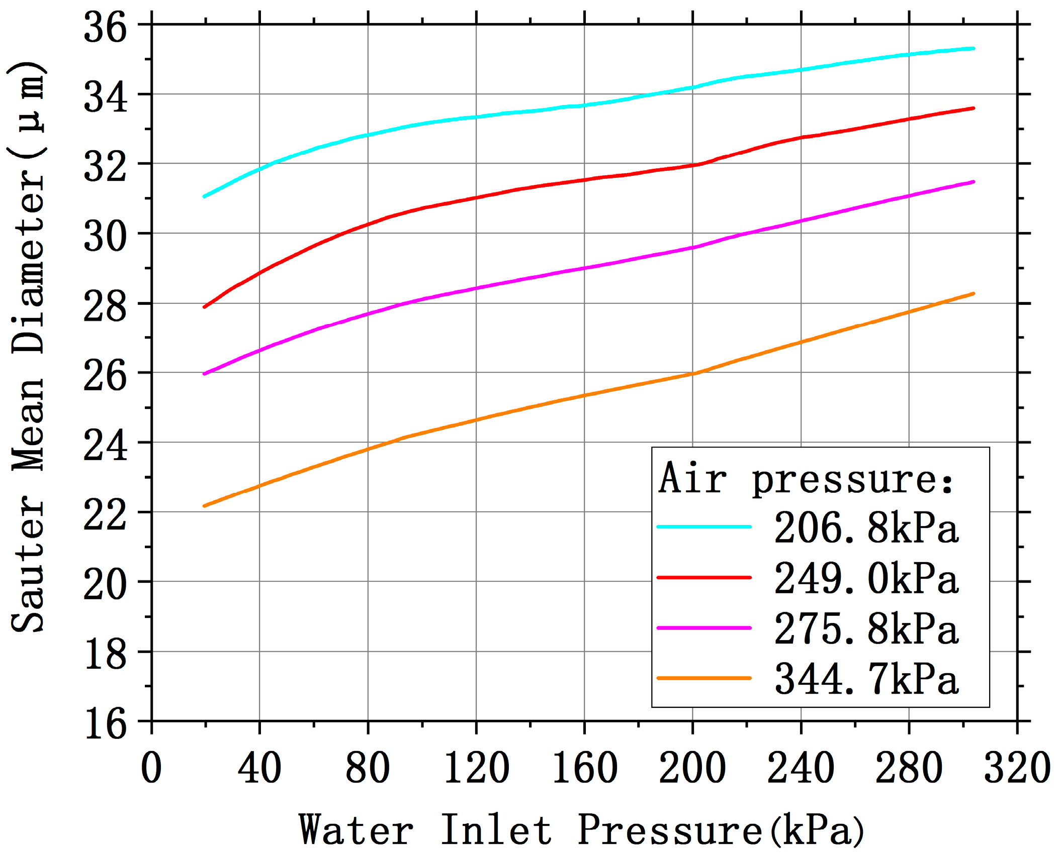
| Orifice Diameter (mm) | Spray Angle (°) | Sauter Mean Diameter (μm) | Spray Volumetric Flow Rate (L·h−1) |
|---|---|---|---|
| 1.1 | 16.9–4.3 | 22.1–35.4 | 3.91–14.53 |
| Temperature (°C) | Thermal Diffusivity (m2·s−1) | Specific Heat at Constant Pressure (J·kg−1·K−1) | Density (kg·m−3) | Thermal Conductivity (W·m−1·K−1) |
|---|---|---|---|---|
| 25 | 470.8632 | 270.55 | ||
| 100 | 480.8412 | 289.50 |
| Case | Various Parameters Description | |
|---|---|---|
| Pressure Difference between Water Inlet Pressure and the Cavity One (kPa) | Spray Volumetric Flow Rate (L·h−1) | |
| 1 | 51.90 | 9.08 |
| 2 | 93.73 | 9.08 |
| 3 | 145.85 | 9.08 |
| 4 | 201.61 | 9.08 |
| 5 | 235.35 | 9.08 |
| 6 | 145.85 | 3.91 |
| 7 | 145.85 | 4.97 |
| 8 | 145.85 | 9.08 |
| 9 | 145.85 | 13.66 |
| 10 | 145.85 | 14.53 |
| Heat Flux (W·cm−2) | PDWIC (kPa) | Temperature (°C) | Temperature Reduction | Heat Transfer Coefficient (W·cm−2·K) | Heat Transfer Coefficient Enhancement |
|---|---|---|---|---|---|
| 32.18 | 51.90 | 35.49 | / | 2.56 | / |
| 235.35 | 25.10 | −29.28% | 14.87 | 480.86% | |
| 63.19 | 51.90 | 52.00 | / | 2.17 | / |
| 235.35 | 28.89 | −44.44% | 10.62 | 388.35% | |
| 100.37 | 51.90 | 65.94 | / | 2.33 | / |
| 235.35 | 36.04 | −45.34% | 7.66 | 228.34% | |
| 139.90 | 51.90 | 78.61 | / | 2.51 | / |
| 235.35 | 42.72 | −45.66% | 7.07 | 181.41% | |
| 181.34 | 51.90 | 94.61 | / | 2.53 | / |
| 235.35 | 51.07 | −46.02% | 6.45 | 154.76% | |
| 222.73 | 51.90 | 106.52 | / | 2.66 | / |
| 235.35 | 56.72 | −46.75% | 6.59 | 147.43% |
| Case | SVFR (L·h−1) | SVFR Enhancement | Temperature (°C) | Temperature Reduction | Heat Transfer Coefficient (W·cm−2·K) | Heat Transfer Coefficient Enhancement |
|---|---|---|---|---|---|---|
| 6 | 3.91 | / | 105.56 | / | 2.67 | / |
| 7 | 4.97 | 27.11% | 86.53 | −18.03% | 3.49 | 30.71% |
| 8 | 9.08 | 132.23% | 74.19 | −29.72% | 4.36 | 63.30% |
| 9 | 13.66 | 249.36% | 59.56 | −43.58% | 5.80 | 117.23% |
| 10 | 14.53 | 271.61% | 55.32 | −47.59% | 6.55 | 145.32% |
© 2019 by the authors. Licensee MDPI, Basel, Switzerland. This article is an open access article distributed under the terms and conditions of the Creative Commons Attribution (CC BY) license (http://creativecommons.org/licenses/by/4.0/).
Share and Cite
Li, J.-X.; Li, Y.-Z.; Cai, B.-Y.; Li, E.-H. Experimental Investigation on Heat Transfer Mechanism of Air-Blast-Spray-Cooling System with a Two-Phase Ejector Loop for Aeronautical Application. Energies 2019, 12, 3963. https://doi.org/10.3390/en12203963
Li J-X, Li Y-Z, Cai B-Y, Li E-H. Experimental Investigation on Heat Transfer Mechanism of Air-Blast-Spray-Cooling System with a Two-Phase Ejector Loop for Aeronautical Application. Energies. 2019; 12(20):3963. https://doi.org/10.3390/en12203963
Chicago/Turabian StyleLi, Jia-Xin, Yun-Ze Li, Ben-Yuan Cai, and En-Hui Li. 2019. "Experimental Investigation on Heat Transfer Mechanism of Air-Blast-Spray-Cooling System with a Two-Phase Ejector Loop for Aeronautical Application" Energies 12, no. 20: 3963. https://doi.org/10.3390/en12203963
APA StyleLi, J.-X., Li, Y.-Z., Cai, B.-Y., & Li, E.-H. (2019). Experimental Investigation on Heat Transfer Mechanism of Air-Blast-Spray-Cooling System with a Two-Phase Ejector Loop for Aeronautical Application. Energies, 12(20), 3963. https://doi.org/10.3390/en12203963