Article

Numerical Investigation of Heat Transfer to Supercritical Water in Vertical Tube under Semicircular Heating Condition

1
China Special Equipment Inspection and Research Institute, Beijing 100029, China
2
China Coal Research Institute Company of Energy Conservation, Beijing 100013, China
*
Author to whom correspondence should be addressed.
Energies 2019, 12(20), 3958; https://doi.org/10.3390/en12203958
Submission received: 20 August 2019 / Revised: 8 October 2019 / Accepted: 10 October 2019 / Published: 18 October 2019

Abstract

:
In-depth understanding and analysis of turbulent convection heat transfer of supercritical water under semicircular heating conditions play a major role in system design and security. The inaccurate numerical results on simulating the buoyancy effect under deterioration heat transfer cases are partly attributed to the invalidity of the turbulent model. An improved turbulence model, which is validated suitable to three-dimensional model, is adopted in the present paper to numerical simulated flow and heat transfer in a vertical tube under semicircular heating condition. Heat transfer deterioration phenomenon occurs under semicircular heating condition, while the degree of deterioration is weakened due to the influence of variable physical properties and buoyancy effect. The velocity profile is distorted into “M-shape” in the heating side and present parabolic distribution in the adiabatic side, leading to different deterioration mechanisms under semicircular heating condition compared with uniform heating. The larger density difference between the heating side and the adiabatic side increases the shear stress production of turbulent kinetic energy; turbulent development is much faster recovery than the phenomenon in uniform heating condition. The results show that the semicircular heating condition can effectively alleviate the degree of heat transfer deterioration in a vertical tube.

1. Introduction

Convection heat transfer of supercritical fluid in vertical tube received much more attention due to high efficiency in various supercritical fluid flow applications, such as supercritical boiler, solar thermal power systems, chemical engineering, power engineering, and aerospace engineering. There exist nonuniform heat flux distribution in these supercritical fluid flow applications, which leads to uneven distribution of wall temperature and internal flow field. In-depth analysis and understanding of the convection heat transfer characteristics of supercritical fluid in vertical tubes with nonuniform heat flux distribution play a major role in system design and optimization.
Supercritical fluid flow and heat transfer in uniform heated vertical tubes have been extensively studied in the former researches Despite the relatively simple geometry involved in many of these applications, the flow and heat transfer of supercritical fluid are different from the conventional fluid, which can be extremely affected by small fluid temperature and pressure variations. At fixed pressure, a small temperature variation in the vicinity of pseudo-critical temperature will cause significant changes in the thermophysical properties, as shown in Figure 1 [1]. The effect of buoyancy in the case of turbulent mixed convection dramatically differs from laminar mixed convection in a uniform heated vertical tube that heat transfer is impaired in buoyancy-aided flow and enhanced in the buoyancy-opposed flow. Heat transfer deterioration (HTD) occurs in the upward flow vertical pipe, characterized by a drastic increase of wall temperature with the velocity distorted into “M-shape” in the vicinity of the wall. Further, shear stress in that region decreases and turbulence is reduced, impairing the turbulent diffusion of heat [2]. The effects of buoyancy on turbulent flow and heat transfer were previously discussed by Jackson and Hall [3,4]. A semi-empirical model for a fully developed, turbulently mixed, convection heat transfer in a uniformly heated vertical tube was developed to evaluate the influence of buoyancy on the convection heat transfer. A series of experimental studies on convection heat transfer of supercritical pressure fluid has been completed [5,6], and the thermal hydraulic phenomenon in the loop is measured simultaneously visualized by dynamic neutron radiography techniques [7]. More recent experimental heat transfer studies have been carried out by Pis’menny [8], Gu [9], Licht et al. [10], and Mokry et al. [11] under conditions of supercritical water in circular tubes at high heat fluxes. Convection heat transfer of supercritical carbon dioxide in vertical heated circular tubes with different interior diameters have been carried out by Jiang et al. [12,13,14], Zhao et al. [15], and Song et al. [16]. Detailed literature reviews about the experiments of supercritical fluid can be found in Duffey and Pioro [17]. A series of empirical correlations based on Dittus–Boelter correlation has been proposed to predict heat transfer to supercritical fluid. The empirical correlations [18,19] under forced convective heat transfer conditions have been found to work reasonably well, due to the absence of heat transfer deterioration. As the buoyancy affects heat transfer condition, the empirical correlations [20,21,22] are not performing well enough due to the drastic variation of thermal properties.
Turbulent convection heat transfer of supercritical pressure fluid in uniform heated vertical tubes has been studied using a variety of computational formulations and turbulence models. The turbulence models invalided in some HTD cases (upward flow) due to the buoyancy effect, and the renormalization group (RNG) k-ε, shear stress transport (SST) k-ω, and low Reynolds number k-ε (LRN k-ε) have been researched in recent studies [23,24,25,26,27,28,29,30,31,32]. Direct numerical simulation (DNS) of CO2 at supercritical pressures conducted by Bae et al. [33], and the large eddy simulation (LES) of turbulent heat transfer at supercritical pressures conducted by Niceno and Sharabi [34], provided detailed information on the flow, turbulence, and thermal fields for improvement or modification of the Reynolds-averaged Navier–Stokes based models (RANS models). Some scholars improve the accuracy of the turbulence model by modifying the model of the turbulent Prandtl number and the model of the buoyancy production of turbulent kinetic energy. Mohseni et al. [27] and Bae et al. [30,31] considered the effect of varying thermophysical properties on the turbulent Prandtl number, using a formulation of the turbulent Prandtl number in the energy equation which varied with the definition of y+. Both regimes of enhanced and deteriorated heat transfer were investigated in these studies, and a better agreement with the experimental data was reached in some HTD cases. Zhang et al. [26], Xiong and Cheng [28], and Pucciarelli et al. [29] considered the four-equation turbulence models in association with advanced hypotheses for the calculation of the turbulent heat flux, such as the Algebraic Heat Flux Models (AHFM). This approach demonstrates some better predictive capabilities than previously adopted models in HTD cases. Jiang et al. [35] proposed a method that considers the anisotropic turbulent heat flux to improve the prediction accuracy of numerical simulation. A buoyancy effect model accounting for the production of turbulent kinetic energy and a turbulent Prandtl number model accounting for turbulent thermal diffusion, which are both based on the anisotropic turbulent heat flux model, were adopted in the original Abe–Kondoh–Nagano (AKN) k-ε model. Experimental results and direct numerical simulations (DNS) data were used to validate the performance of the “Modified model”.
Research on the issue of convection heat transfer to supercritical pressure fluid under semicircular heating condition is not comprehensive enough. Ishikawa et al. [36] found that the heat transfer coefficient distributed unevenly in the circumferential direction by employing semicircular resistance furnace heating. Hu et al. [37] showed that the maximum circumferential difference of wall decreased from 30 K to 10 K as bulk temperature close to Tpc when the heat flux was relatively low. Li et al. [38] numerically studied the heat transfer of supercritical water for flow in a vertical tube which was heated on one side. The results show that the buoyancy effect is much stronger in upward flow than in downward flow, and the local deterioration is not as severe as uniformly heated cases. Zhang et al. [39] proposed the relation between the threshold incident solar heat flux and mass flux for the supercritical water to avoid deterioration in the heat transfer of supercritical water for one-side heating. Qu and Yang [40] experimentally and numerically investigated heat transfer of ultra-supercritical water in a vertical upward tube under uniform heating and nonuniform heating conditions. The peak value of the wall temperature is higher under nonuniform heating. Meanwhile, the heat flux is higher when heat transfer deterioration occurs. In view of the above, more accurate turbulence model and deep analysis of convection heat transfer of supercritical pressure fluid in nonuniform heating tube are needed.
In the present paper, numerical simulations of supercritical water in vertical tube under semicircular heating condition was conducted using a modified method based on the low Reynolds number k-ε model. After validating the model by the experimental data, detailed information on velocity, turbulence fields are presented, and the mechanisms of buoyancy effect induced by the semicircular heating are also discussed.

2. Modeling

2.1. Turbulent Model

The steady-state governing equations for continuity, momentum, and energy are as follows:
x i ( ρ u i ) = 0
x j ( ρ u i u j ) = P x i + ρ g i + x j [ μ ( u i x j + u j x i ) u i u j ¯ ]
x i ( ρ u i c p T ) = x i ( λ T x i ρ c p u i T ¯ )
where u i u j ¯ is the turbulent stress tensor and u i T ¯ is the turbulent heat flux vector.
The turbulent stress tensor u i u j ¯ is expressed by modeled transport equations for scalar variables, k-ε, in two equations RANS turbulence model. The two equation k-ε turbulence model demonstrated suitable for numerical simulation of convection heat transfer of supercritical pressure fluid:
x i ( ρ u i k ) = x i [ ( μ + μ t σ k ) k x i ] + P k + G k ρ ε
x i ( ρ u i ε ) = x i [ ( μ + μ t σ k ) ε x i ] + C ε 1 f 1 ε k ( P k + G k ) C ε 2 f 2 ρ ε 2 k
where Pk and Gk are the turbulent kinetic energy produced by shear stress and buoyancy, respectively. The expressions follow:
P k = ρ u i u j ¯ u i x j , G k = ρ β g i u i T ¯
The AKN k-ε model is used to calculate the turbulent viscosity:
μ t = ρ C μ f μ k 2 ε
The turbulent heat flux, u i T ¯ is an important term to describe convection heat transfer with respect to the buoyancy effect. The Algebraic Heat Flux Model (AHFM) is used to model turbulent heat flux, and the simplified method was proposed by Jiang et al. [35], which is used in the present paper.
u i T ¯ = C t k ε [ C t 1 u i u j ¯ T x j + ( 1 C t 2 ) u i T ¯ u i x j + ( 1 C t 3 ) β g i T 2 ¯ ]
T 2 ¯ = 1 c T k ε u i T ¯ T x i

2.2. Numerical Method

As shown in Figure 2, the physical model is a vertical tube with a wall thickness (δ) of 0.91 mm, which is in accordance with the experimental setup in Pis’menny [8]. The diameter of the tube is 6.28 mm, and the heated section is 95 times diameter with an additional isothermal flow section in the upstream and downstream section. Heat flux is arranged in the semicircular direction of the pipeline, and the other side is the adiabatic boundary condition. The circumferential angle (α) in the middle of the hot side is defined as 0°. No-slip condition is specified at the tube inner surface. The inlet of the isothermal section is set as constant velocity inlet, and the outlet is set as pressure outlet boundary condition. According to the experimental setup, Table 1 lists the cases studied in the present paper. Case “C1–C3” refers to the convection heat transfer of supercritical water in the vertical uniform heated tube, and case “D1–D3” refers to the semicircular heating cases with the heat flux arranged in the range of 0° < α < 180°.
The computational study was conducted by Ansys Fluent 13.0 [41], and the grid is divided into hexahedral structured mesh by the Integrated Computer Engineering and Manufacturing code for Computational Fluid Dynamics (ICEM CFD 13.0), as shown in Figure 3. In order to accurately predict the supercritical pressure water flow and heat transfer in the boundary layer, the mesh is refined near the wall in the fluid region, and the first layer mesh close to the wall is small enough to satisfy the y+ less than 1. The size of the radial grid increases by 1.05 times until the grid size reaches 0.01 D. The mesh along the axial direction is evenly distributed with a grid size of 0.159 D.
The pressure velocity coupling adopts the Semi-Implicit Method for Pressure Linked Equations (SIMPLE) algorithm, and the momentum equation and the energy equation adopt the second-order upwind scheme difference method. The convergence condition is such that the residuals of all equations are less than 10−6. The supercritical pressure water properties were calculated by the physical property software (National Institute of Standards and Technology, NIST) and added to the software using piecewise linear fitting and user-defined methods. The turbulent kinetic energy generation term and the turbulent Prandtl number is calculated based on the turbulent heat flux model, which is added to the original AKN k-ε model by User Defined Function (UDF). All the UDF codes were extended to the three-dimensional coordinates.

2.3. Model Validation

The size of the local grid will affect the numerical calculation results. Hence, the grid verification and model accuracy validation are needed. The number of different meshes is given in Table 2; the circumferential mesh size and the first layer mesh are different. The “m1” grid has a larger first layer distance from the wall than the other two grids, and the “m2” grid has a larger circumferential grid size than the “m3” grid. As shown in Figure 4, the numerical simulation results calculated by the “m1” grid are slightly different from those results calculated by “m2” and “m3”. The difference in results is mainly reflected in the area where heat transfer is deteriorated. The calculated results will be affected by the sparse grid near the tube wall due to the stronger influence of buoyancy effect in this area. The original turbulent model cannot capture the basic temperature trend along the tube, meanwhile obtain an exaggerated result which is several times the experimental results. The modified model used in the present paper could obtain a more accurate temperature distribution and temperature magnitude, predicting a more accurate wall temperature peak position. Based on such a situation, the model could be considered validated, and the model can be used to obtain internal flow field and temperature field details. Taking into account the cost and time of calculation, the “m2” grid is used in the present paper.
As shown in Figure 4, the three-dimensional model considering the wall thickness and the calculation results are slightly different from the results calculated by the two-dimensional axisymmetric model without considering the wall thickness. The main reason is that when considering the wall thickness, the model is set such that the heat flux is transferred from the outer wall of the tube to the fluid in the tube by heat conduction. This setting increases the amount of heat transfer, resulting in a three-dimensional result wall temperature higher than the two-dimensional results. When the three-dimensional model does not consider the wall thickness, the results are consistent with the results of the two-dimensional axisymmetric model. Therefore, the numerical model is able to satisfactorily predict heat transfer to supercritical water in a semicircular heated tube.

3. Numerical Results and Discussion

3.1. Influence of Semicircular Heating Form on Flow and Heat Transfer

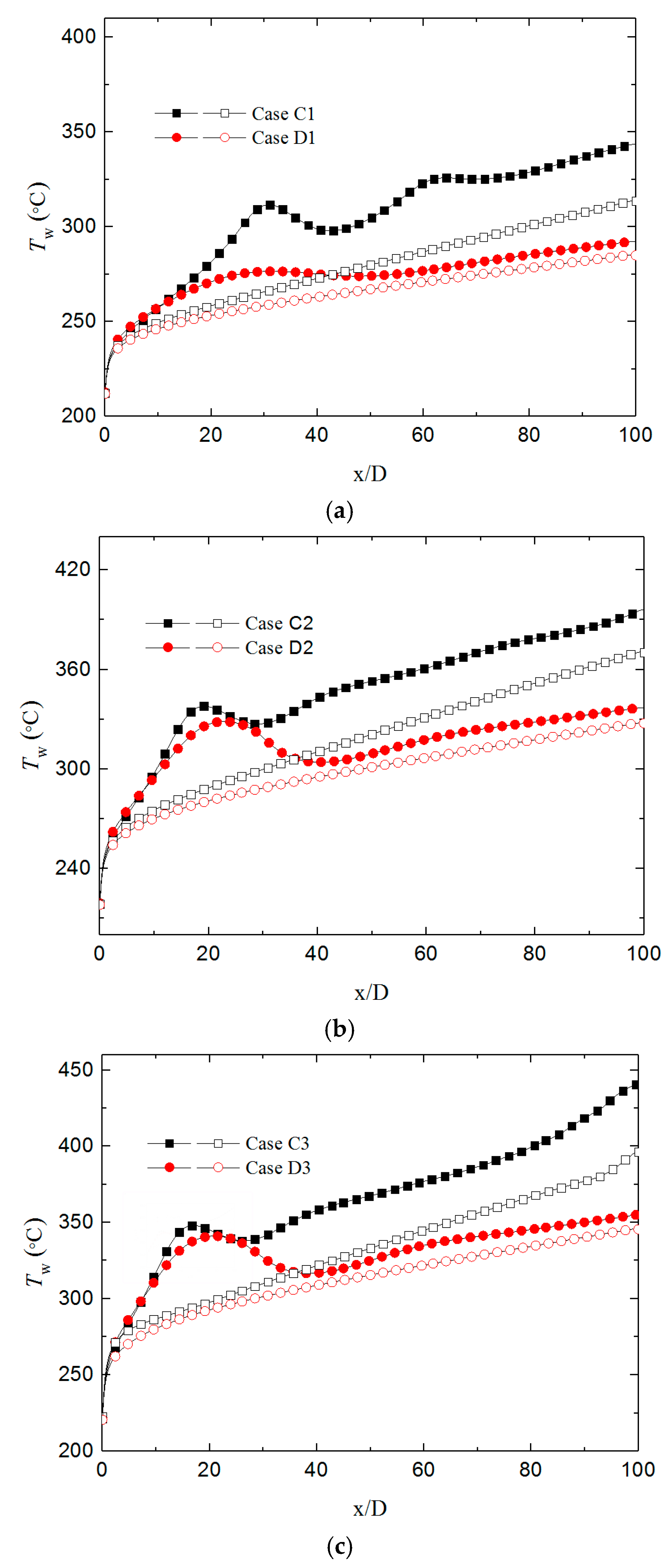
As shown in Figure 5, flow and heat transfer is affected by the buoyancy effect, and two heating forms result in different wall temperature along the tube. The wall temperature is lower in the condition of downward than upward flow in the conditions of uniform and semicircular heating form, which means all the heat transfer is deteriorated by the buoyancy effect both for the two forms. Under relatively low heat flux conditions (qw = 167 kW/m2), the temperature value in the condition of uniform heating is much higher than the semicircular heating. The maximum temperature difference between the condition of uniform heating and the semicircular heating is about 51.3 °C. As the heat flux increase, the wall temperature value is similar to both heating form in the most heat transfer deterioration region. In the peak temperature area, the minimum temperature difference is about 2.1 °C between the two heating forms, and the minimum error is about 0.66%.
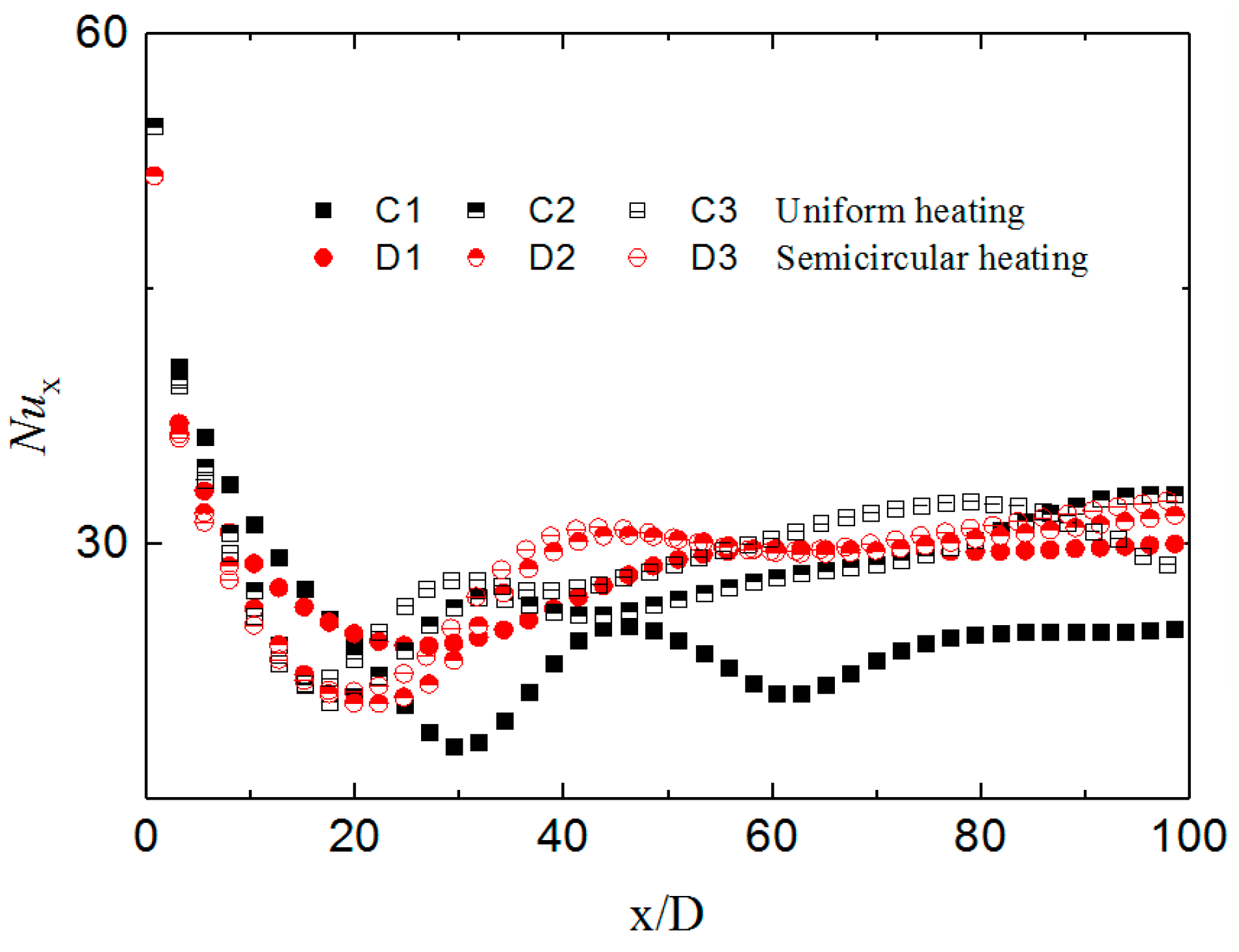
Figure 6 shows the Nusselt number of supercritical water in the vertical tube under the two heating form. At the lower heat flux condition (qw = 167 kW/m2), the Nu number of semicircular heating form is higher than the uniform heating pattern. As the heat flux increase, Nu number in the two forms are gradually similar to each other. In the entrance region of the tube, the degree of the heat transfer deterioration is similar for the two-heating pattern, and the Nu number distribution along the tube almost coincides; the maximum error is about 4.6%. When the heat flux is high, the buoyancy effect distorts the velocity profile and suppress turbulent development for both uniform heating and semicircular heating form.
The temperature field is centrally symmetric in the uniform heating condition, and the temperature filed is symmetrical along the location of α = 90° in the semicircular heating condition, as shown in Figure 7. Under the uniform heating form, heat flux transfer from the outside of the tube to the fluid through heat conduction and convection, the temperature of each circular section is equal. As for semicircular heating condition, the heat flux is located in the range of 0° < α < 180°, the maximum temperature is lower than the case of uniform heating form due to the wall thickness of the tube has a circumferential thermal conduction effect. As the heat flux increase, the circumferential thermal conduction effect is gradually weakened in the location of α = 90°, and the wall temperature is gradually approaching in two heating form.
The velocity profile of case D2 in the location of x/D = 30 is shown in Figure 8, and the velocity profile is distorted by the effect of the semicircular heating pattern. The distribution of temperature filed lead to different density in the cross-section, due to the one-to-one correspondence. The velocity profile in different circumferential direction has been bent into a different form, which is influenced by the density filed. On the adiabatic side of α = 270°, the maximum velocity is in the center of the tube. The velocity profile is distorted into “M-shape” on the heating side of α = 90°, and the maximum velocity is in the location near the tube wall. As shown in Figure 9, the maximum density difference appears in the circumferential direction of α = 90°. The large density difference makes the buoyancy effect significant at this section, and the shear stress changes accordingly. Under the condition of semicircular heating, the influence of variable physical properties and buoyancy effect on heat transfer is different from that under uniform heating conditions, and the mechanism of heat transfer deterioration induced by the semicircular heating form will be analyzed in the next section.

3.2. Mechanism of Buoyancy Effect on Heat Transfer Deterioration in Semicircular Heating Form

Under the semicircular heating condition, the phenomenon of heat transfer deterioration is different from the cases of the uniform heating condition. With the increase of heat flux, the degree of heat transfer deterioration under semicircular heating in the entrance region is gradually close to the condition of uniform heating form. The heat transfer intensity in the rear region of the tube is slightly higher than the uniform heat flow condition, and indicating that the mechanism of heat transfer deterioration under semicircular heating flow conditions is different from that under uniform heating flow conditions.
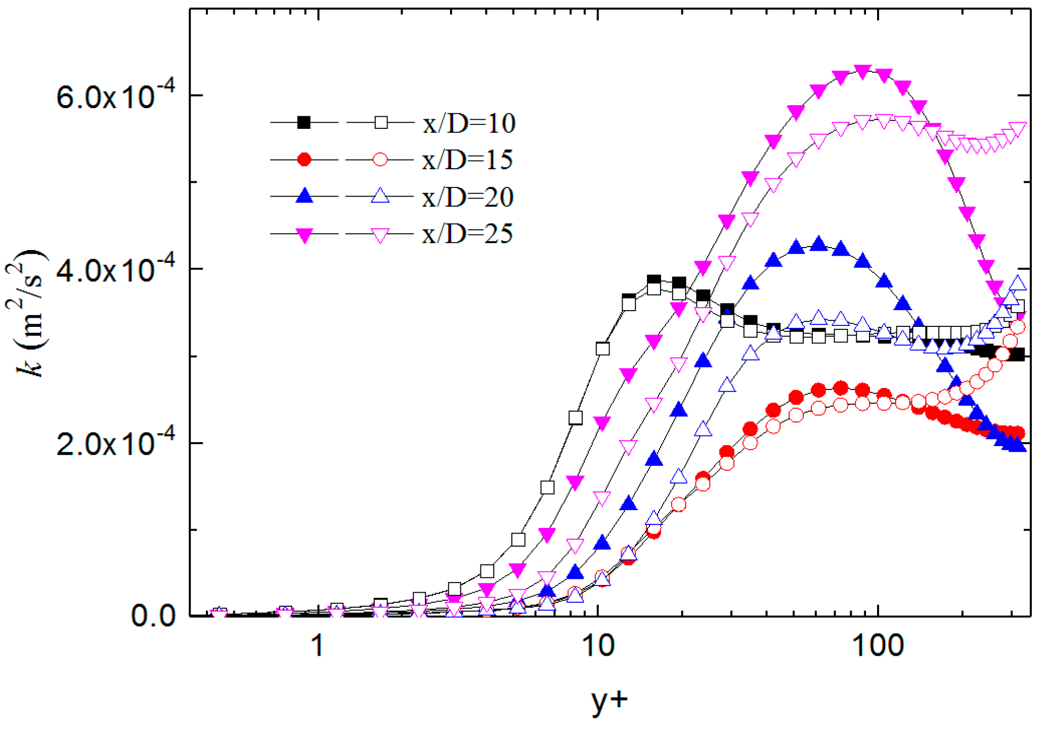
As shown in Figure 10, in the range of x/D = 10 to x/D = 25, the turbulent kinetic energy distribution on the cross-section almost coincides for the two heating form. Especially in the range of 5 < y+ < 60, the kinetic energy curves almost coincide, the turbulent kinetic energy also decreases first and then increases for the two heating form. In the range of x/D = 10 to x/D = 25, a similar magnitude and trend of turbulent kinetic energy lead to a similar wall temperature distribution and convection heat transfer intensity.
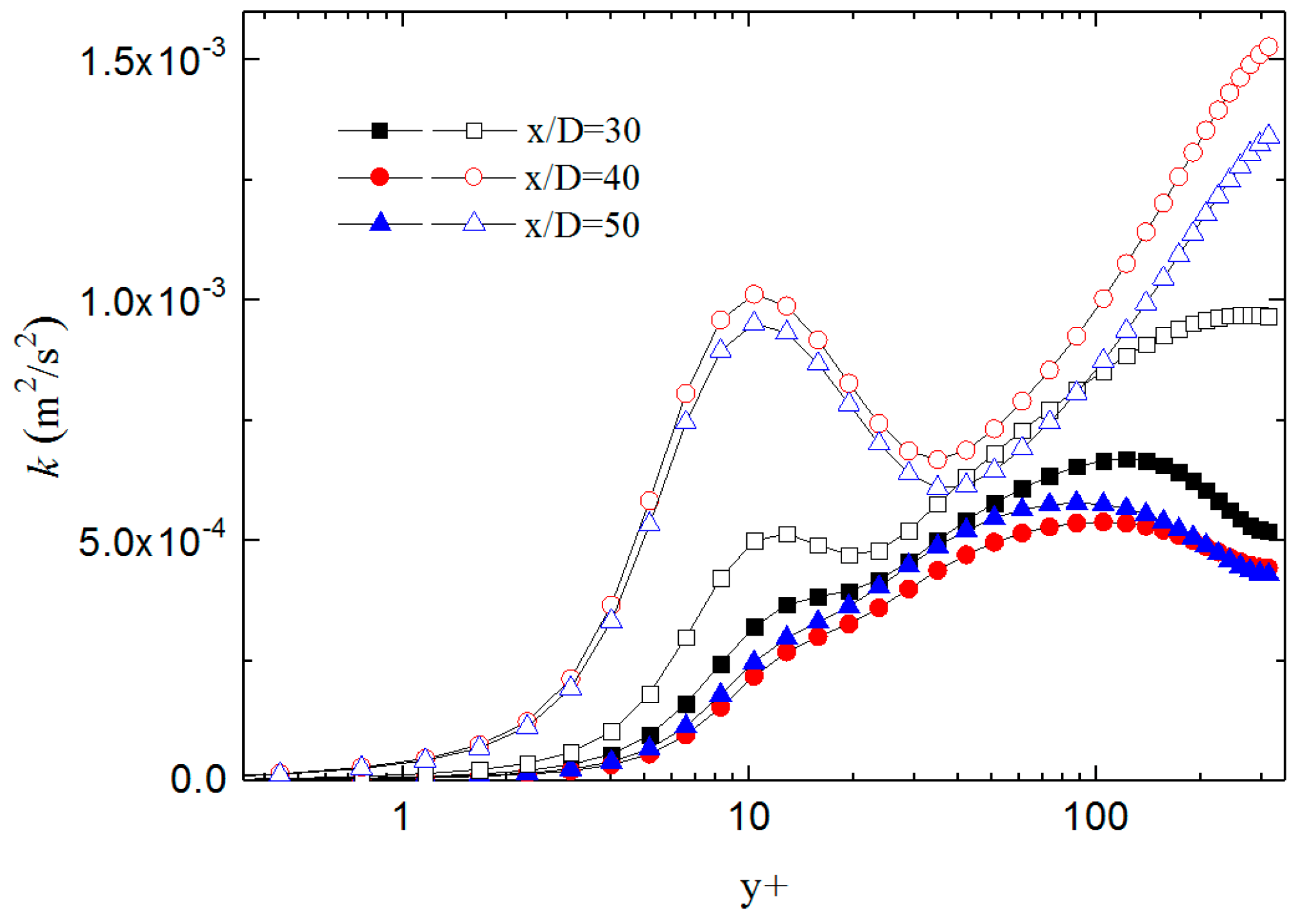
The turbulent kinetic energy distribution in the range of x/D = 30 to x/D = 50 for the two heating form is shown in Figure 11. The turbulent kinetic energy along the tube shows a rising trend for the two heating form, hence the convective heat transfer intensity is increased, and the wall temperature is lower relative to the peak value. The turbulent kinetic energy under the condition of semicircular heating is no longer consistent with the uniform heating form, and the turbulent kinetic energy at different cross-sections is higher than the value of the uniform heating form. Such a tendency of turbulent kinetic energy distribution results in wall temperature lower than the value of the uniform heating form. In the semicircular heating form, the buoyancy effect leads to rapid recovery of turbulent development, and the heat transfer deterioration is weakened.
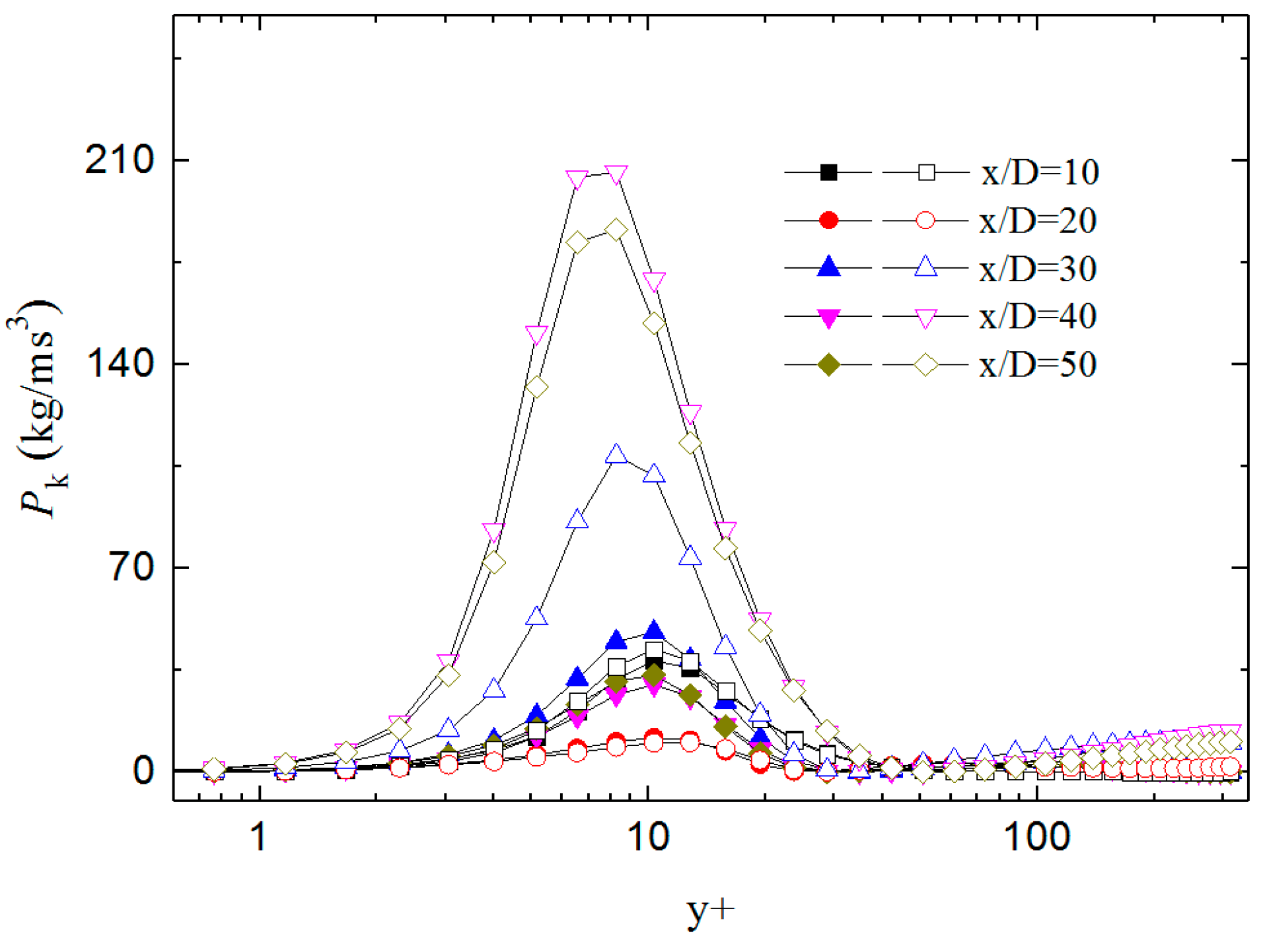
Figure 12 shows the comparison of shear stress production of turbulent kinetic energy (Pk) in the range of x/D = 10 to x/D = 50 for the two heating form. The profile of Pk term in the range of x/D = 10 to x/D = 20 has almost coincided for the two heating form. With the range of x/D > 30, the Pk term under semicircular heating from is gradually higher than the value under the uniform heating form. On the heating side, the fluid density is gradually reduced due to heating and the density on the adiabatic side is less changed. Such a density distribution enhanced the buoyancy effect, and the distorted degree of the velocity profile is increased under the buoyancy effect. The shear effect enhanced near the heating side and the Pk term is increased, which induced higher turbulent kinetic energy under the nonuniform heating form, and the heat transfer deterioration is weakened.

4. Conclusions

This paper numerically simulated the flow and heat transfer of supercritical water in a vertical semicircular heating tube by a modified turbulent model. The verification results show that the improved model is also applicable to the three-dimensional calculation model, which can accurately predict the influence of semicircular heating conditions on the flow and heat transfer of supercritical water in the vertical tube. Under the semicircular heating condition, heat transfer deterioration phenomenon occurs characteristically by wall temperature in upward flow is higher than the value in a downward flow. The semicircular heating condition reduces the degree of heat transfer deterioration due to the buoyancy effect which is induced by the large density difference in the cross-section. The larger density difference between the heating side and the adiabatic side increases the shear stress production of turbulent kinetic energy, and turbulent development has been restored much faster than the condition of uniform heating form. The results show that the semicircular heating condition can effectively alleviate the degree of heat transfer deterioration.

Author Contributions

Conceptualization, Z.W. and G.Q.; Investigation, Z.W. and M.L.; Software, Z.W. and M.L.; Supervision, G.Q.; Writing—original draft, Z.W.; Writing—review & editing, Z.W., G.Q. and M.L.

Funding

This project was supported by the National Key R&D Program of China (No. 2018YFF0216000) and CSEI Research Program (No. 201806).

Conflicts of Interest

The authors declare no conflict of interest.

References

  1. Imre, A.; Deiters, U.; Kraska, T.; Tiselj, I.; Imre, A. The pseudocritical regions for supercritical water. Nucl. Eng. Des. 2012, 252, 179–183. [Google Scholar] [CrossRef]
  2. Kim, W.; He, S.; Jackson, J. Assessment by comparison with DNS data of turbulence models used in simulations of mixed convection. Int. J. Heat Mass Transf. 2008, 51, 1293–1312. [Google Scholar] [CrossRef]
  3. Jackson, J.D.; Hall, W.B. Forced convection heat transfer to fluids at supercritical pressure, in: Turbulent Forced Convection in Channels and Bundles. Hemisphere 1979, 2, 563–611. [Google Scholar]
  4. Hall, W.B.; Jackson, J.D.; Watson, A. A review of forced convection heat transfer to fluids at supercritical pressures. Proc. Inst. Mech. Eng. 1967, 182, 10–22. [Google Scholar] [CrossRef]
  5. Shitsmanm, M.E. Impairment of heat transmission at supercritical pressures. High Temp 1963, 1, 237–244. [Google Scholar]
  6. Fewster, J. Mixed Forced and Free Convective Heat Transfer to Supercritical Pressure Fluids Flowing in Vertical Pipes. Ph.D. Thesis, University of Manchester, Manchester, UK, 1976. [Google Scholar]
  7. Balaskó, M.; Horváth, L.; Horváth, Á.; Kiss, A.; Aszodi, A. Study on the Properties of Supercritical Water Flowing in a Closed Loop using Dynamic Neutron Radiography. Phys. Procedia 2013, 43, 254–263. [Google Scholar] [CrossRef] [Green Version]
  8. Pis’Menny, E.N.; Razumovskiy, V.G.; Maevskiy, E.M.; Koloskov, A.E.; Pioro, I.L. Heat Transfer to Supercritical Water in Gaseous State or Affected by Mixed Convection in Vertical Tubes. In Proceedings of the 14th International Conference on Nuclear Engineering, Miami, FL, USA, 17–20 July 2006. [Google Scholar]
  9. Gu, H.; Zhao, M.; Cheng, X. Experimental studies on heat transfer to supercritical water in circular tubes at high heat fluxes. Exp. Therm. Fluid Sci. 2015, 65, 22–32. [Google Scholar] [CrossRef]
  10. Licht, J.; Anderson, M.; Corradini, M. Heat transfer to water at supercritical pressures in a circular and square annular flow geometry. Int. J. Heat Fluid Flow 2008, 29, 156–166. [Google Scholar] [CrossRef]
  11. Mokry, S.; Pioro, I.; Kirillov, P.; Gospodinov, Y. Supercritical-water heat transfer in a vertical bare tube. Nucl. Eng. Des. 2010, 240, 568–576. [Google Scholar] [CrossRef]
  12. Jiang, P.X.; Xu, Y.J.; Lv, J.; Shi, R.F.; He, S.; Jackson, J.D. Experimental investigation of convection heat transfer of CO2, at super-critical pressures in vertical mini-tubes and in porous media. Appl. Therm. Eng. 2004, 24, 1255–1270. [Google Scholar] [CrossRef]
  13. Jiang, P.X.; Zhang, Y.; Xu, Y.J.; Shi, R.F. Experimental and numerical investigation of convection heat transfer of CO2 at supercritical pressures in a vertical tube at low Reynolds numbers. Int. J. Heat Mass Transf. 2010, 47, 998–1011. [Google Scholar] [CrossRef]
  14. Jiang, P.X.; Zhang, Y.; Zhao, C.R.; Shi, R.F. Convection heat transfer of CO2, at supercritical pressures in a vertical mini tube at relatively low reynolds numbers. Exp. Therm. Fluid Sci. 2008, 32, 1628–1637. [Google Scholar] [CrossRef]
  15. Liao, S.; Zhao, T. An experimental investigation of convection heat transfer to supercritical carbon dioxide in miniature tubes. Int. J. Heat Mass Transf. 2002, 45, 5025–5034. [Google Scholar] [CrossRef]
  16. Song, J.H.; Kim, H.Y.; Kim, H.; Bae, Y.Y. Heat transfer characteristics of a supercritical fluid flow in a vertical pipe. J. Supercrit. Fluids 2008, 44, 164–171. [Google Scholar] [CrossRef]
  17. Duffey, R.B.; Pioro, I.L. Experimental heat transfer of supercritical carbon dioxide flowing inside channels (survey). Nucl. Eng. Des. 2005, 235, 913–924. [Google Scholar] [CrossRef]
  18. Jackson, J.D.; Cotton, M.A.; Axcell, B.P. Studies of mixed convection in vertical tubes. Int. J. Heat Fluid Flow 1989, 10, 2–15. [Google Scholar] [CrossRef]
  19. Griem, H. A new procedure for the prediction of forced convection heat transfer at near- and supercritical pressure. Heat Mass Transf. 1996, 31, 301–305. [Google Scholar] [CrossRef]
  20. Jackson, J.D. Fluid flow and convective heat transfer to fluids at supercritical pressure. Nucl. Eng. Des. 2013, 264, 24–40. [Google Scholar] [CrossRef]
  21. Kim, J.K.; Hong, K.J.; Lee, J.S. Wall temperature measurement and heat transfer correlation of turbulent supercritical carbon dioxide flow in vertical circular/non-circular tubes. Nucl. Eng. Des. 2007, 237, 1795–1802. [Google Scholar] [CrossRef]
  22. Bae, Y.-Y.; Kim, H.-Y. Convective heat transfer to CO2 at a supercritical pressure flowing vertically upward in tubes and an annular channel. Exp. Therm. Fluid Sci. 2009, 33, 329–339. [Google Scholar] [CrossRef]
  23. Wen, Q.; Gu, H. Numerical simulation of heat transfer deterioration phenomenon in supercritical water through vertical tube. Ann. Nucl. Energy 2010, 37, 1272–1280. [Google Scholar] [CrossRef]
  24. He, S.; Kim, W.S.; Jiang, P.X.; Jackson, J.D. Simulation of mixed convection heat transfer to carbon dioxide at supercritical pressure. Proc. Inst. Mech. Eng. Part C J. Mech. Eng. Sci. 2004, 218, 1281–1296. [Google Scholar] [CrossRef]
  25. He, S.; Kim, W.; Bae, J. Assessment of performance of turbulence models in predicting supercritical pressure heat transfer in a vertical tube. Int. J. Heat Mass Transf. 2008, 51, 4659–4675. [Google Scholar] [CrossRef]
  26. Zhang, G.; Zhang, H.; Gu, H.; Yang, Y.; Cheng, X. Experimental and numerical investigation of turbulent convective heat transfer deterioration of supercritical water in vertical tube. Nucl. Eng. Des. 2012, 248, 226–237. [Google Scholar] [CrossRef]
  27. Mohseni, M.; Bazargan, M. A New Correlation for the Turbulent Prandtl Number in Upward Rounded Tubes in Supercritical Fluid Flows. J. Heat Transf. 2016, 138, 081701. [Google Scholar] [CrossRef]
  28. Xiong, J.; Cheng, X. Turbulence modelling for supercritical pressure heat transfer in upward tube flow. Nucl. Eng. Des. 2014, 270, 249–258. [Google Scholar] [CrossRef]
  29. Pucciarelli, A.; Sharabi, M.; Ambrosini, W. Prediction of heat transfer to supercritical fluids by the use of Algebraic Heat Flux Models. Nucl. Eng. Des. 2012, 297, 257–266. [Google Scholar] [CrossRef]
  30. Bae, Y.Y. A new formulation of variable turbulent Prandtl number for heat transfer to supercritical fluids. Int. J. Heat Mass Transf. 2016, 92, 792–806. [Google Scholar] [CrossRef]
  31. Bae, Y.-Y.; Kim, E.-S.; Kim, M. Numerical simulation of supercritical pressure fluids with property-dependent turbulent Prandtl number and variable damping function. Int. J. Heat Mass Transf. 2016, 101, 488–501. [Google Scholar] [CrossRef]
  32. Zhao, C.R.; Zhang, Z.; Jiang, P.X.; Bo, H.L. Influence of various aspects of low Reynolds number k-ε turbulence models on predicting in-tube buoyancy affected heat transfer to supercritical pressure fluids. Nucl. Eng. Des. 2017, 313, 401–413. [Google Scholar] [CrossRef]
  33. Bae, J.H.; Yoo, J.Y.; Choi, H. Direct numerical simulation of turbulent supercritical flows with heat transfer. Phys. Fluids 2005, 17, 105104. [Google Scholar] [CrossRef]
  34. Niceno, B.; Sharabi, M. Large eddy simulation of turbulent heat transfer at supercritical pressures. Nucl. Eng. Des. 2013, 261, 44–55. [Google Scholar] [CrossRef]
  35. Jiang, P.-X.; Wang, Z.-C.; Xu, R.-N. A modified buoyancy effect correction method on turbulent convection heat transfer of supercritical pressure fluid based on RANS model. Int. J. Heat Mass Transf. 2018, 127, 257–267. [Google Scholar] [CrossRef]
  36. Ishikawa, H.; Suhara, S.; Abe, T.; Takahashi, T. Forced Convection Heat Transfer to Supercritical Water from Semicricular Heated Surface in Vertical Tube(part1) the Design of Experimental Equipment and Measurement of Heat Transfer Coefficient; Report No. 277015; Central Research Institute of Electric Power Industry: Tokyo, Japan, 1977. [Google Scholar]
  37. Hu, Z.H. Heat Transfer Characteristics of Vertical Upflow and Inclined Tube in the Supercritical Pressure and Near-Critical Pressure Region. Ph.D. Thesis, Xi’an Jiaotong University, Xi’an, China, 2001. [Google Scholar]
  38. Li, Z.H.; Wu, Y.X.; Lu, J.F.; Zhang, D.; Zhang, H. Heat transfer to supercritical water in circular tubes with circumferentially non-uniform heating. Appl. Therm. Eng. 2014, 70, 190–200. [Google Scholar] [CrossRef]
  39. Zhang, G.; Li, Y.; Dai, Y.; Wang, R. Heat transfer to supercritical water in a vertical tube with concentrated incident solar heat flux on one side. Int. J. Heat Mass Transf. 2016, 95, 944–952. [Google Scholar] [CrossRef]
  40. Qu, M.; Yang, D.; Liang, Z.; Wan, L.; Liu, D. Experimental and numerical investigations on heat transfer of ultra-supercritical water in vertical upward tube under uniform and non-uniform heating. Int. J. Heat Mass Transf. 2018, 127, 769–783. [Google Scholar] [CrossRef]
  41. ANSYS Inc. ANSYS Fluent Theory Guide Release 13.0.; ANSYS Inc.: Canonsburg, PA, USA, 2011. [Google Scholar]
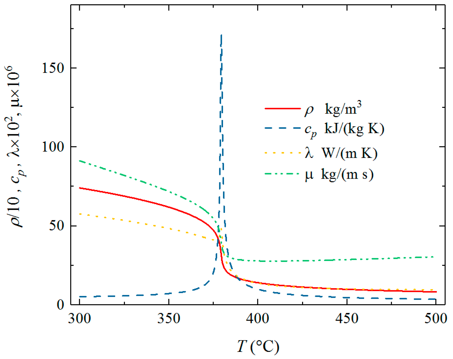
Figure 1. Thermophysical properties for water at 23.0 Mpa.
Energies 12 03958 g001
Figure 2. Geometry and boundary condition.
Energies 12 03958 g002
Figure 3. Computational meshes.
Energies 12 03958 g003
Figure 4. Grid independence analysis and model validation.
Energies 12 03958 g004
Figure 5. Wall temperature (α = 90°): (a) qw = 167 kW/m2, (b) qw = 253 kW/m2, (c) qw = 289 kW/m2 (Solid: Upward flow; Hollow: Downward flow).
Energies 12 03958 g005
Figure 6. Nusselt number (α = 90°).
Energies 12 03958 g006
Figure 7. Temperature filed at different location: (a) uniform heating, (b) semicircular heating.
Energies 12 03958 g007
Figure 8. Case D2 velocity profile in the location of x/D = 30.
Energies 12 03958 g008
Figure 9. Case D2 density profile in the location of x/D = 30.
Energies 12 03958 g009
Figure 10. Comparison of turbulent kinetic energy in different location (Solid: C2; Hollow: D2).
Energies 12 03958 g010
Figure 11. Comparison of turbulent kinetic energy in a different location (Solid: C2; Hollow: D2).
Energies 12 03958 g011
Figure 12. Shear stress production of turbulent kinetic energy in different location (Solid: C2; Hollow: D2).
Energies 12 03958 g012
Table 1. Initial/boundary conditions of simulations.
CaseP (MPa)G (kg/m2s)qw (W/m2)
C123.5249167
C223.5249253
C323.5249289
D123.5249167 (0° < α < 180°)
D223.5249253 (0° < α < 180°)
D323.5249289 (0° < α < 180°)
Table 2. Grid number.
MeshCircumferential Grid Size
(°)
First Layer Distance
(y/D)
Grid Quantity
(million)
m14.53.18 × 10−41.5
m231.59 × 10−42.4
m32.251.59 × 10−45.0