Experimental Determination of the Friction Factor in a Tube with Internal Helical Ribs


Abstract
:1. Introduction
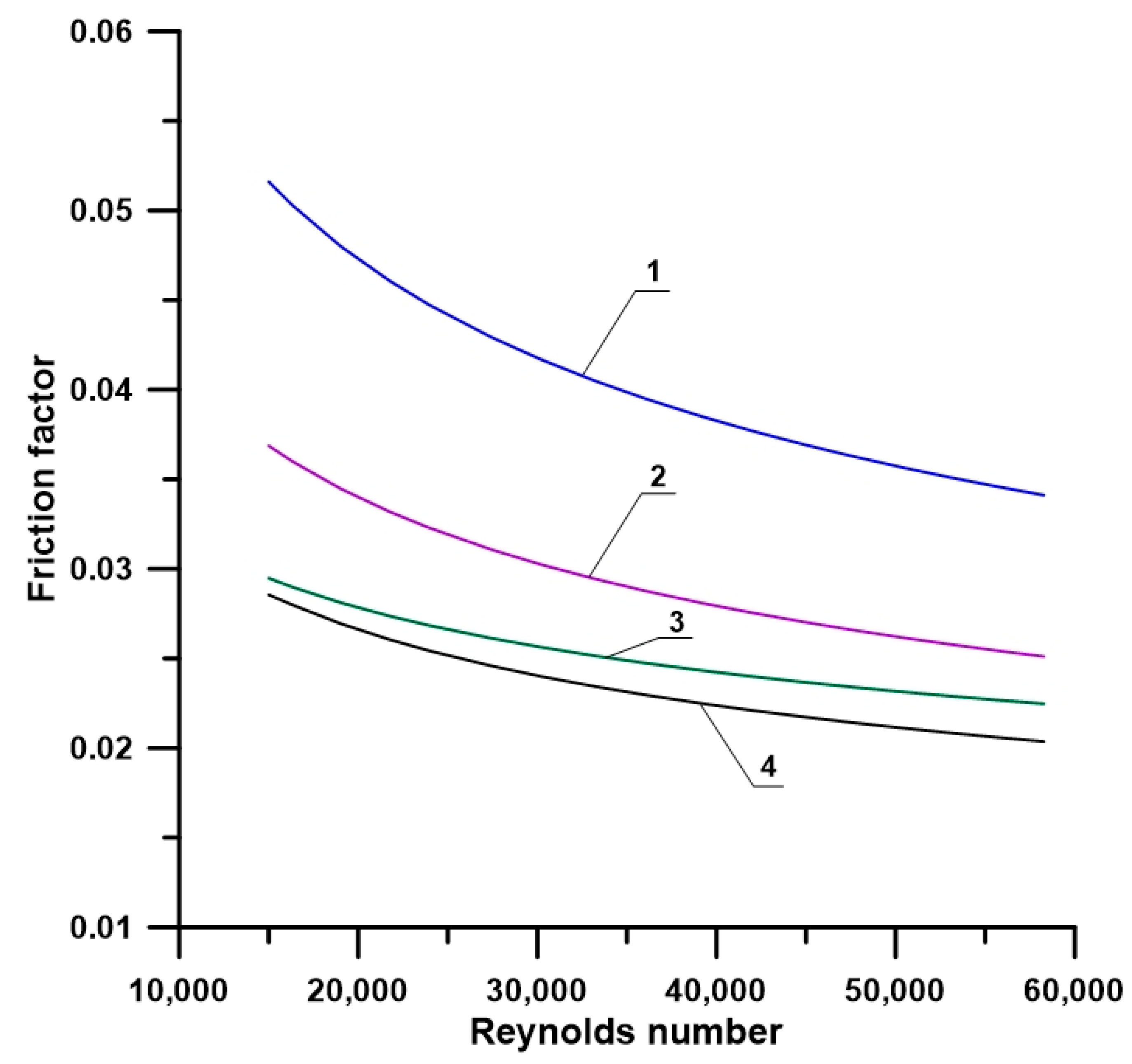
2. Friction Factor in Smooth and Rifled Tubes
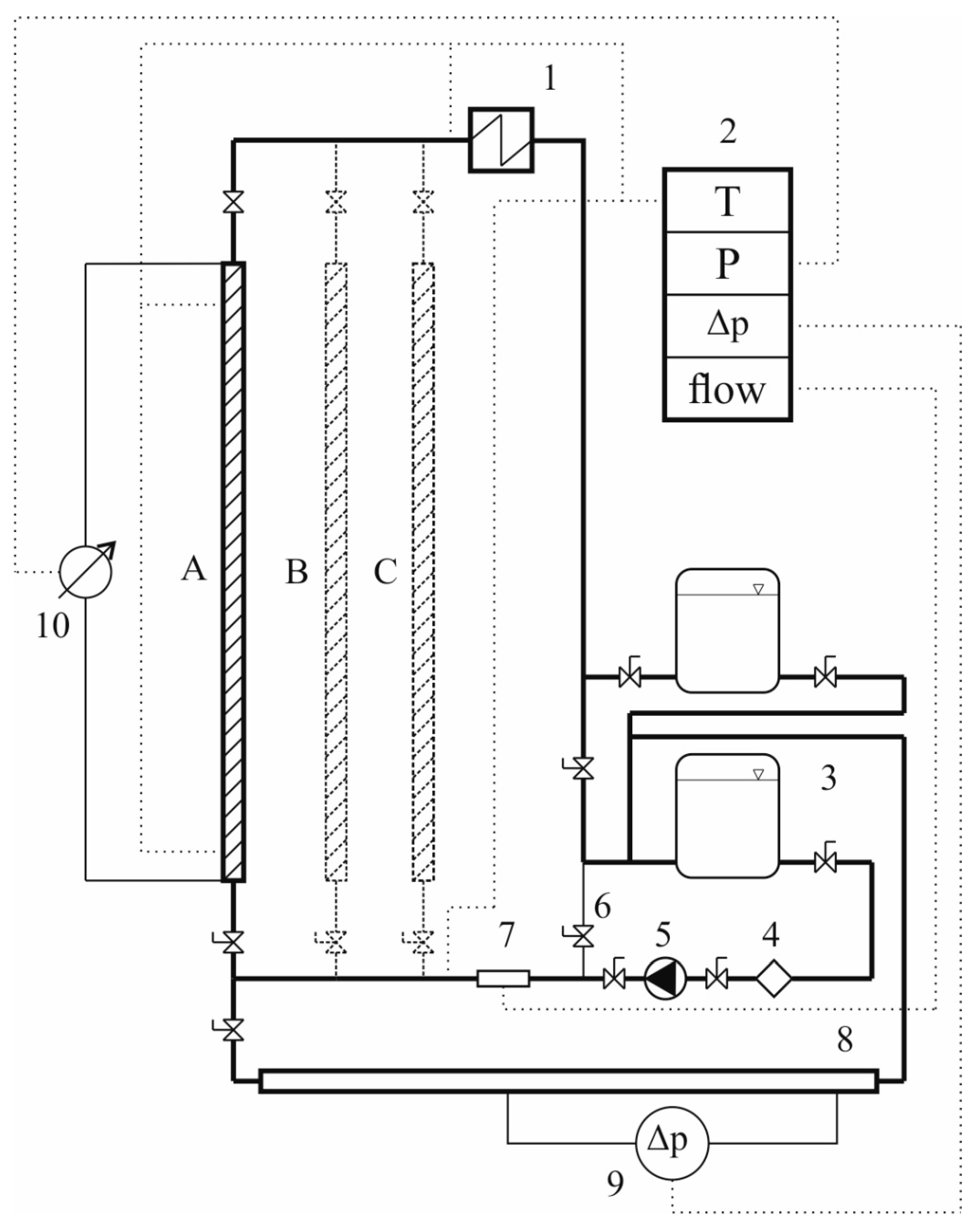
3. Test Stand for Experimental Determination of Pressure Losses in Rifled Tubes
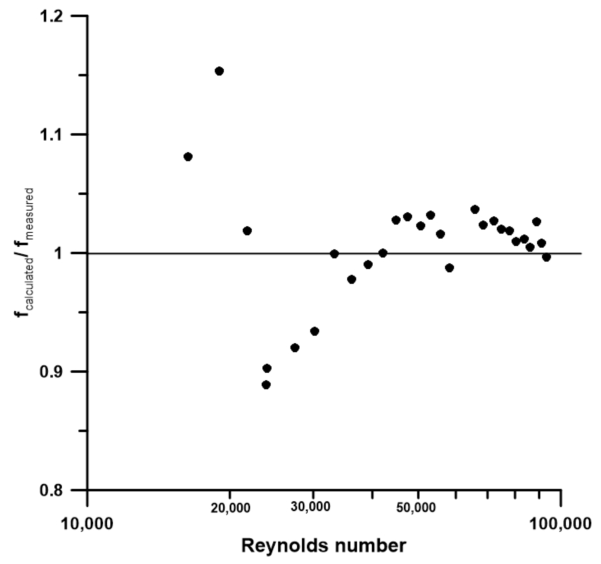
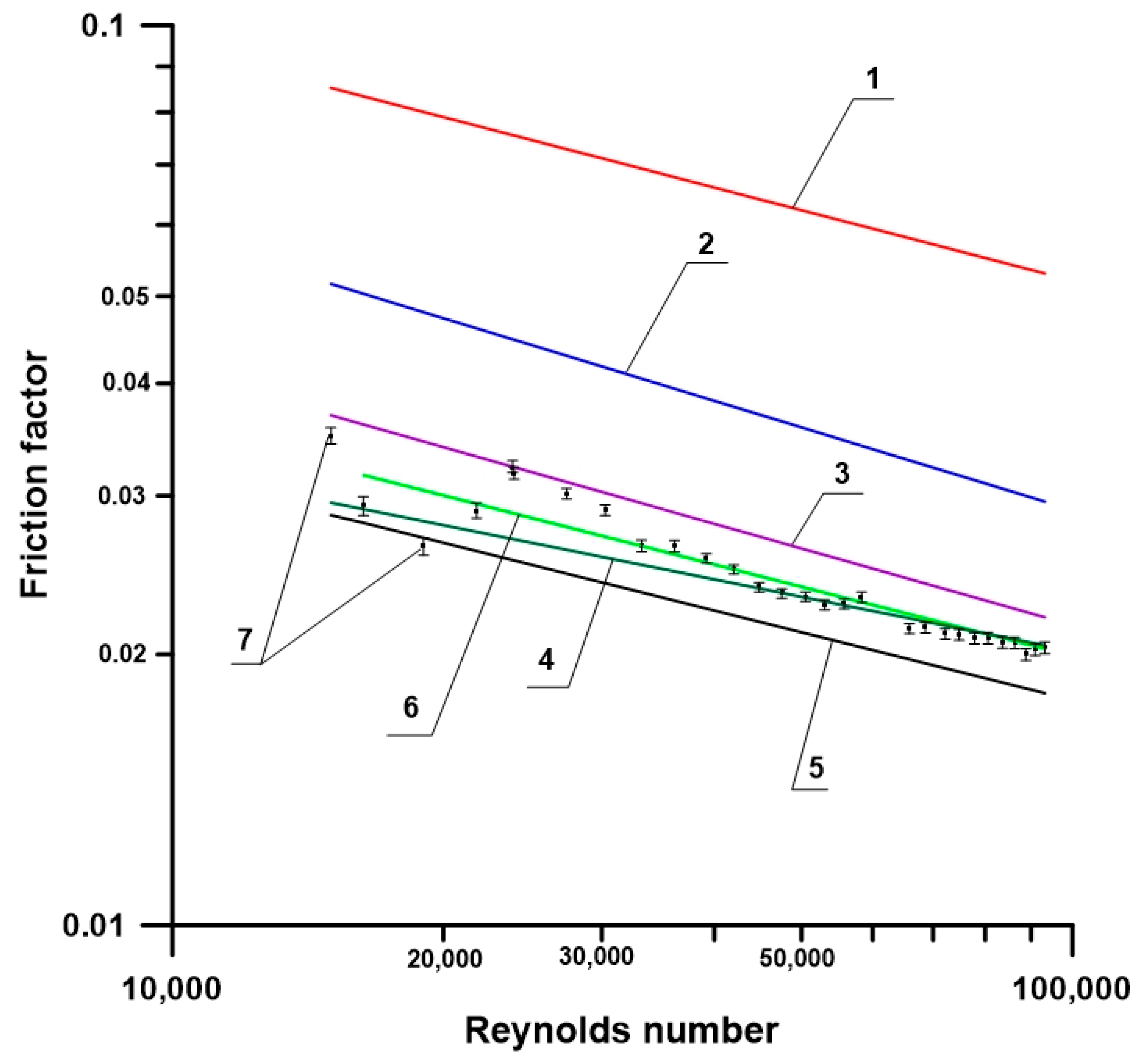
4. Experimental Determination of The Friction Factor
5. Conclusions
Author Contributions
Funding
Conflicts of Interest
Nomenclature
| a | rib width at the base, mm |
| A | area, mm2 |
| An | tube cross-section surface area (ribs not taken into account), mm2 |
| Axs | tube cross-section surface area minus the surface area occupied by ribs, mm2 |
| b | rib average width, mm |
| dh | hudraulic diameter, mm |
| do | outer diameter, mm |
| di | inner diameter (without ribs), mm |
| dmin | minimum diameter, mm |
| e | rib height, mm |
| f | friction factor of smooth tubes |
| fF | friction factor of rifled tubes,- |
| g | wall thickness, mm |
| N | number of ribs in the cross-section, - |
| O | wetted perimeter, m |
| p | pitch, mm |
| Re | Reynolds number |
| u | uncertainty |
| V | volumetric flow, m3/h |
| Greek symbols | |
| α | rib apex angle, |
| β | rib helical angle, |
| Δp | differential pressure, Pa |
| ρ | density, kg/m3 |
| ν | kinematic viscosity coefficient, m2/s |
References
- Kakac, S.; Bergles, A.; Mayinger, F.; Yuncu, H. (Eds.) Heat Transfer Enhancement of Heat Exchangers; Springer: Dordrecht, The Netherlands, 1999; ISBN 978-94-015-9159-1. [Google Scholar] [CrossRef]
- Carnavos, T.C. Cooling of Air in Turbulent Flow with Internally Finned Tubes. Heat Transf. Eng. 1979, 1, 41–46. [Google Scholar] [CrossRef]
- Webb, R.; Narayanamurthy, R.; Thors, P. Heat Transfer and Friction Characteristics of Internal Helical-Rib Roughness. J. Heat Transf. 2000, 122, 134–142. [Google Scholar] [CrossRef]
- Hewitt, G.; Shires, G.; Bott, T. Process Heat Transfer, 1st ed.; CRC Press: London, UK, 1994; pp. 297–325. ISBN 0-8493-9918-1. [Google Scholar]
- Zdaniuk, G.J.; Chamra, L.M.; Mago, P.J. Experimental determination of heat transfer and friction in helically-finned tubes. Exp. Therm. Fluid Sci. 2008, 32, 761–775. [Google Scholar] [CrossRef]
- Zdaniuk, G.J.; Chamra, L.M.; Walters, D.K. Correlating heat transfer and friction in helically-finned tubes using artificial neural networks. Heat Mass Transf. 2008, 50, 4713–4723. [Google Scholar] [CrossRef]
- Zdaniuk, G.J.; Luck, R.; Chamra, L.M. Linear correlation of heat transfer and friction in helically-finned tubes using five simple groups of parameters. Heat Mass Transf. 2008, 51, 3548–3555. [Google Scholar] [CrossRef]
- Cheng, L.; Chen, T. Study of vapour liquid two-phase frictional pressure drop in a vertical heated spirally internally ribbed tubes. Chem. Eng. Sci. 2007, 62, 783–792. [Google Scholar] [CrossRef]
- Weiguo, X.; Depeng, R.; Qing, Y.; Guodong, L.; Huilin, L.; Shuai, W. Simulations and experiments of laminar heat transfer for Therminol heat transfer fluids in a rifled tube. Appl. Therm. Eng. 2016, 102, 861–872. [Google Scholar] [CrossRef]
- Solutia Inc. Therminol 55. Heat Transfer Fluid by Solutia; Solutia Inc.: St. Louis, MO, USA, 2008. [Google Scholar]
- Ackerman, J. Pseudoboiling Heat Transfer to Supercritical Pressure Water in Smooth and Ribbed Tubes. J. Heat Transf. 1969, 92, 490. [Google Scholar] [CrossRef]
- Gee, D.; Webb, R. Forced convection heat transfer in helically rib-roughened tubes. Int. J. Heat Mass Transf. 1980, 23, 1127–1136. [Google Scholar] [CrossRef]
- Zimparov, V.; Vulchanov, N.; Delov, L. Heat transfer and friction characteristics of spirally corrugated tubes for power plant condensers—1. Experimental investigation and performance evaluation. Int. J. Heat Mass Transf. 1991, 34, 2187–2197. [Google Scholar] [CrossRef]
- Ravigururajan, T.; Bergles, A. Development and verification of general correlations for pressure drop and heat transfer in single-phase turbulent flow in enhanced tubes. Exp. Therm. Fluid Sci. 1996, 13, 55–70. [Google Scholar] [CrossRef]
- Cheng, L.; Chen, T.; Luo, Y. Flow boiling heat transfer of kerosene inside ribbed tube. ASME Heat Transf. Div. 1997, 351, 235–241. [Google Scholar]
- Dong, Y.; Huixiong, L.; Tingkuan, C. Pressure drop, heat transfer and performance of single-phase turbulent flow in spirally corrugated tubes. Exp. Therm. Fluid Sci. 2001, 24, 131–138. [Google Scholar] [CrossRef]
- Barba, A.; Rainieri, S.; Spiga, M. Heat transfer enhancement in a corrugated tube. Int. Commun. Heat Mass Transf. 2002, 29, 313–322. [Google Scholar] [CrossRef]
- Vicente, P.; Garcia, A.; Viedma, A. Mixed convection heat transfer and isothermal pressure drop in corrugated tubes for laminar and transition flow. Int. Commun. Heat Mass Transf. 2004, 31, 651–662. [Google Scholar] [CrossRef]
- Wang, J.; Li, H.; Guo, B.; Yu, S.; Zhang, Y.; Chen, T. Investigation of forced convection heat transfer of supercritical pressure water in a vertically upward internally ribbed tube. Nuclear Eng. Des. 2009, 239, 1956–1964. [Google Scholar] [CrossRef]
- Wang, J.; Li, H.; Yu, S.; Chen, T. Investigation on the characteristics and mechanism of unusual heat transfer of supercritical pressure water in vertically-upward tubes. Int. J. Heat Mass Transf. 2011, 54, 1950–1958. [Google Scholar] [CrossRef]
- Yang, D.; Pan, J.; Zhou, C.; Zhu, X.; Bi, Q.; Chen, T. Experimental investigation on heat transfer and frictional characteristics of vertical upward rifled tube in supercritical CFB boiler. Exp. Therm. Fluid Sci. 2011, 35, 291–300. [Google Scholar] [CrossRef]
- Khoeini, D.; Akhavan-Behabadi, M.; Saboonchi, A. Experimental study of condensation heat transfer of R-134a flow in corrugated tubes with different inclinations. Int. Commun. Heat Mass Transf. 2012, 39, 138–143. [Google Scholar] [CrossRef]
- Ji, W.-T.; Zhang, D.-C.; He, Y.-L.; Tao, W.-Q. Prediction of fully developed turbulent heat transfer of internal helically ribbed tubes—An extension of Gnielinski equation. Int. J. Heat Mass Transf. 2012, 55, 1375–1384. [Google Scholar] [CrossRef]
- Lu, J.; Sheng, X.; Ding, J.; Yang, J. Transition and turbulent convective heat transfer of molten salt in spirally grooved tube. Exp. Therm. Fluid Sci. 2013, 47, 180–185. [Google Scholar] [CrossRef]
- Li, Z.; Tang, G.; Wu, Y.; Zhai, Y.; Xu, J.; Wang, H.; Lu, J. Improved gas heaters for supercritical CO2 Rankine cycles: Considerations on forced and mixed convection heat transfer enhancement. Appl. Energy 2016, 178, 126–141. [Google Scholar] [CrossRef]
- Yang, Z.; Chen, W.; Chyu, M.K. Numerical study on the heat transfer enhancement of supercritical CO2 in vertical ribbed tubes. Appl. Therm. Eng. 2018, 145, 705–715. [Google Scholar] [CrossRef]
- Xu, W.; Wang, S.; Liu, G.; Zhang, Q.; Hassan, M.; Lu, H. Experimental and numerical investigation on heat transfer of Therminol heat transfer fluid in an internally four-head ribbed tube. Int. J. Therm. Sci. 2017, 116, 32–44. [Google Scholar] [CrossRef]
- Zhang, Q.; Li, H.; Zhang, W.; Li, L.; Lei, X. Experimental study on heat transfer to the supercritical water upward flow in a vertical tube with internal helical ribs. Int. J. Heat Mass Transf. 2015, 89, 1044–1053. [Google Scholar] [CrossRef]
- Shen, Z.; Yang, D.; Mao, K.; Long, J.; Wang, S. Heat transfer characteristics of water flowing in a vertical upward rifled tube with low mass flux. Exp. Therm. Fluid Sci. 2016, 70, 341–353. [Google Scholar] [CrossRef]
- Massoud, M. Engineering Thermofluids. Thermodynamics, Fluid Mechanics, and Heat Transfer; Springer: Berlin/Heidelberg, Germany, 2005; ISBN 978-3-540-27280-9. [Google Scholar]
- Majewski, K. Concept of a measurement and test station for determining linear pressure drop and heat transfer coefficient of internally ribbed tubes. J. Power Technol. 2013, 93, 340–346. [Google Scholar]
- Pan, J.; Yang, D.; Dong, Z.; Zhu, T.; Bi, Q. Experimental investigation on heat transfer characteristic of low mass flux rifled tube with upward flow. Int. J. Heat Mass Transf. 2011, 54, 2952–2961. [Google Scholar] [CrossRef]
- Zhu, X.; Bi, Q.; Su, Q.; Yang, D.; Wang, J.; Wu, G.; Yu, S. Self-compensating characteristic of steam-water mixture at low mass velocity in vertical upward parallel internally ribbed tubes. Appl. Therm. Eng. 2010, 30, 2370–2377. [Google Scholar] [CrossRef]
- Grądziel, S.; Majewski, K. Simulation of Thermal and Flow Phenomena in Smooth and Internally Rifled Tubes. J. Heat Transf. Eng. 2018, 39, 1243–1250. [Google Scholar] [CrossRef]
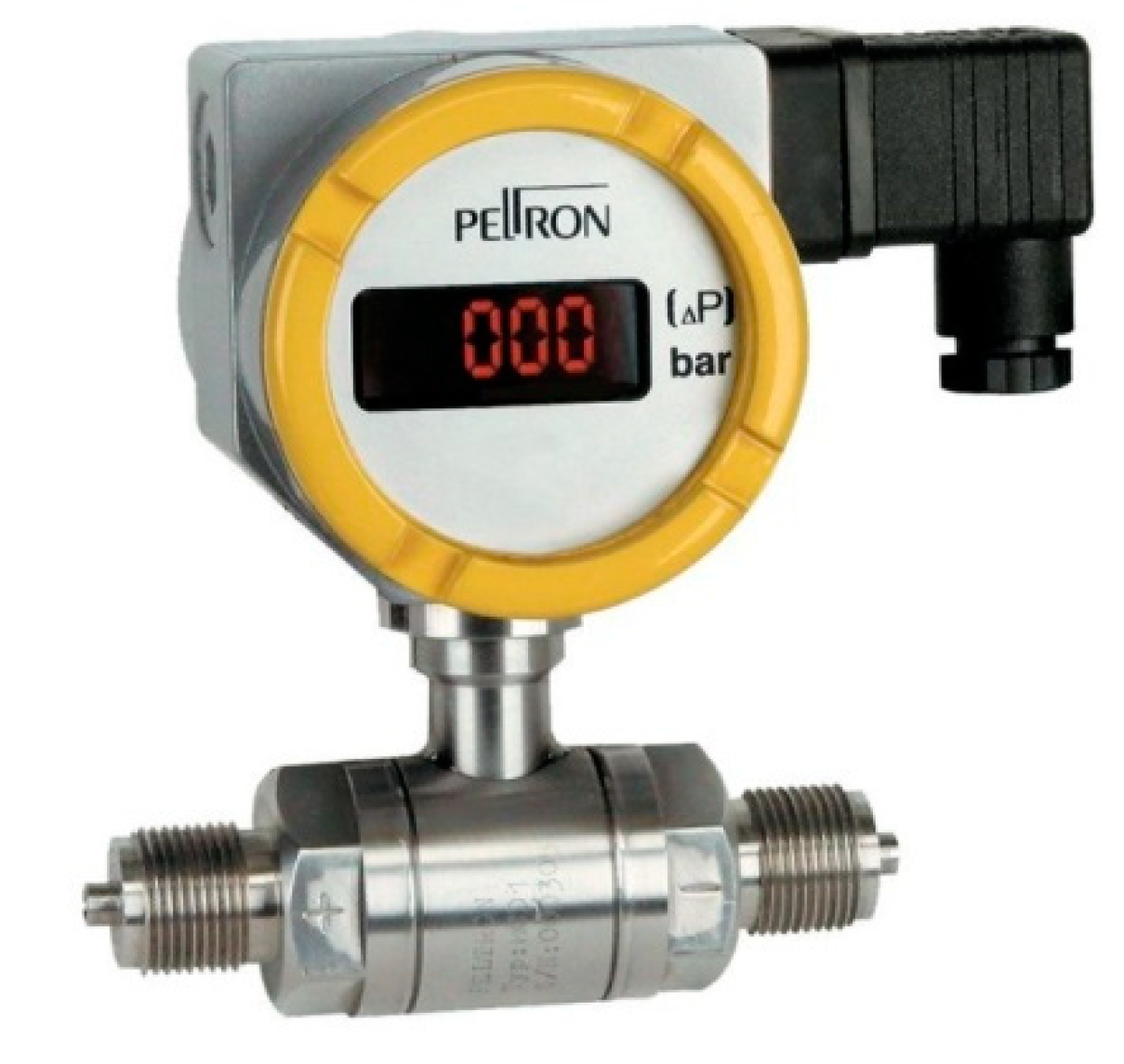
- Peltron. Available online: www.peltron.pl (accessed on 6 June 2017).
- ASME International. Policy on Reporting Uncertainties in Experimental Measurements and Results. J. Heat Transf. Policy 1993, 115, 5–6. [Google Scholar] [CrossRef]
- Systat Software, Inc. TableCurve 2D—Curve Fitting Made Fast and Easy. Available online: http://www.sigmaplot.co.uk/products/tablecurve2d/tablecurve2d.php (accessed on 5 June 2017).
- Jensen, M.; Vlakancic, A. Technical note. Experimental investigation of turbulent heat transfer and fluid flow in internally finned tubes. Heat Mass Transf. 1999, 42, 1343–1351. [Google Scholar] [CrossRef]


| Researcher | Working Fluid | Inner Diameter di [mm] | Pitch p [mm] | Rib Height e [mm] |
|---|---|---|---|---|
| Ackerman [11] | Supercritical pressure water | 18 | 21.8 | 0.9 |
| Gee and Webb [12] | Air | 25.4 | 3.81 | 0.25 |
| Zimparov et al. [13] | Water | 25.0 | 6.5–16.9 | 0.44–1.18 |
| Ravigururajan and Bergles [14] | Water and air | 14.0–22.86 | 4.16–10.16 | 0.89–1.78 |
| Cheng et al. [15] | Oil | 11.0 | 5.5 | 0.5 |
| Dong et al. [16] | Water and oil | 19.0–25.0 | 10.0–12.0 | 0.39–0.8 |
| Barba et al. [17] | Water | 14.5 | 11.5 | 1.5 |
| Vicente et al. [18] | Water and glycol | 18.0 | 10.9–22.1 | 0.42–1.03 |
| Wang et al. [19,20] | Supercritical pressure water | 18.6 | 11.6 | 1.2 |
| Yang et al. [21] | Two-phase mixture | 21.0 | 22.7 | 0.85 |
| Khoeini et al. [22] | R-134a | 9.52 | 8.0 | 1.5 |
| Ji et al. [23] | Water | 18.9–19.1 | - | 0.39–0.45 |
| Lu et al. [24] | Liquid salt | 10.2 | 3.2 | 0.38–0.76 |
| Li et al. [25] | Supercritical CO2 | 16.5 | - | 0.85 |
| Yang et al. [26] | Supercritical CO2 | 9.0 | 10.0–20.0 | 0.25–0.90 |
| Weiguo et al. [27] | Therminol 55 | 14.2 | 21.0 | 0.85 |
| Zhang et al. [28] | Supercritical pressure water | 20.62 | 12.87 | 1.25 |
| Shen et al. [29] | Subcritical pressure water | 18.96 | 18.1 | 1.24 |
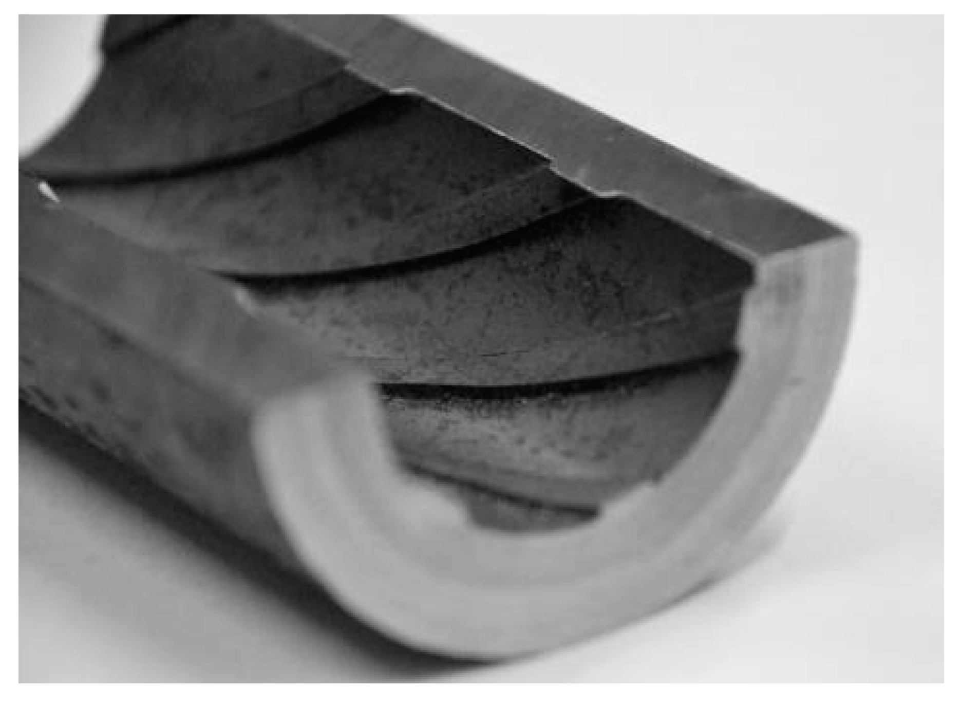
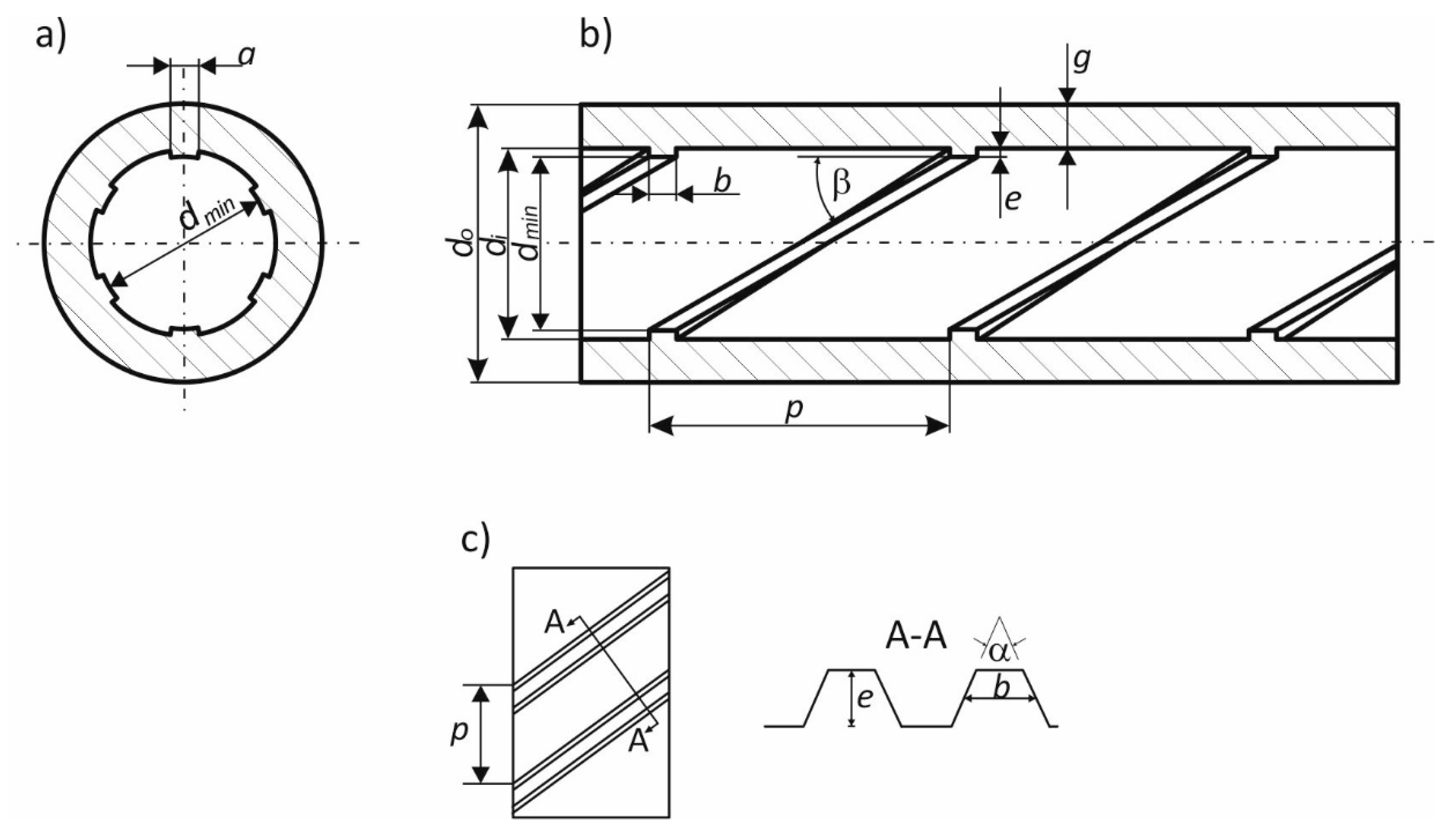
| Characteristic Dimension | Value |
|---|---|
| Outer diameter, do | 50.8 mm |
| Inner diameter (without ribs), di | 34.9 mm |
| Minimum diameter, dmin | 32.9 mm |
| Wall thickness, g | 7.95 mm |
| Rib height, e | 1 mm |
| Pitch, p | 30 mm |
| Rib width at the base, a | 5 mm |
| Rib average width, b | 4.5 mm |
| Rib apex angle, α | 45° |
| Rib helical angle, β | 30° |
| Number of ribs in the cross-section, N | 6 |
| No. | Measured Flow V m3/h | Fluid Temperature t °C | Density ρ kg/m3 | Kinematic Viscosity Coefficient ν m2/s | Reynolds Number Re | Measured Differential Pressure Δp Pa | Friction Factor fF | Uncertainty u(f) |
|---|---|---|---|---|---|---|---|---|
| 1 | 8.028 | 22.8 | 997.59 | 9.43 × 10⁻⁷ | 93195 | 2326.58 | 0.0204 | 0.0003 |
| 2 | 7.800 | 23.0 | 997.55 | 9.40 × 10⁻⁷ | 90888 | 2184.68 | 0.0203 | 0.0003 |
| 3 | 7.580 | 23.2 | 997.50 | 9.35 × 10⁻⁷ | 88751 | 2038.65 | 0.0200 | 0.0003 |
| 4 | 7.331 | 23.4 | 997.45 | 9.31 × 10⁻⁷ | 86231 | 1962.47 | 0.0206 | 0.0003 |
| 5 | 7.079 | 23.6 | 997.41 | 9.27 × 10⁻⁷ | 83623 | 1831.70 | 0.0206 | 0.0003 |
| 6 | 6.811 | 23.7 | 997.39 | 9.25 × 10⁻⁷ | 80613 | 1715.03 | 0.0209 | 0.0003 |
| 7 | 6.564 | 23.7 | 997.37 | 9.24 × 10⁻⁷ | 77790 | 1592.57 | 0.0208 | 0.0003 |
| 8 | 6.294 | 23.9 | 997.34 | 9.21 × 10⁻⁷ | 74849 | 1477.20 | 0.0210 | 0.0003 |
| 9 | 6.054 | 24.0 | 997.29 | 9.17 × 10⁻⁷ | 72282 | 1369.14 | 0.0211 | 0.0003 |
| 10 | 5.763 | 23.9 | 997.32 | 9.19 × 10⁻⁷ | 68648 | 1261.42 | 0.0214 | 0.0003 |
| 11 | 5.512 | 24.1 | 997.27 | 9.15 × 10⁻⁷ | 65934 | 1150.97 | 0.0214 | 0.0003 |
| 12 | 5.147 | 21.7 | 997.85 | 9.67 × 10⁻⁷ | 58279 | 1088.23 | 0.0232 | 0.0003 |
| 13 | 4.942 | 21.5 | 997.89 | 9.70 × 10⁻⁷ | 55768 | 986.23 | 0.0228 | 0.0003 |
| 14 | 4.679 | 21.8 | 997.83 | 9.65 × 10⁻⁷ | 53072 | 881.18 | 0.0227 | 0.0003 |
| 15 | 4.454 | 21.8 | 997.83 | 9.65 × 10⁻⁷ | 50523 | 815.94 | 0.0232 | 0.0003 |
| 16 | 4.176 | 21.9 | 997.80 | 9.62 × 10⁻⁷ | 47529 | 723.04 | 0.0234 | 0.0003 |
| 17 | 3.946 | 21.9 | 997.80 | 9.62 × 10⁻⁷ | 44894 | 656.44 | 0.0238 | 0.0003 |
| 18 | 3.694 | 21.9 | 997.80 | 9.62 × 10⁻⁷ | 42040 | 601.64 | 0.0249 | 0.0003 |
| 19 | 3.441 | 22.0 | 997.79 | 9.61 × 10⁻⁷ | 39214 | 536.43 | 0.0255 | 0.0003 |
| 20 | 3.156 | 22.2 | 997.74 | 9.56 × 10⁻⁷ | 36142 | 466.61 | 0.0264 | 0.0004 |
| 21 | 2.912 | 22.0 | 997.78 | 9.60 × 10⁻⁷ | 33211 | 397.07 | 0.0264 | 0.0004 |
| 22 | 2.654 | 22.0 | 997.78 | 9.60 × 10⁻⁷ | 30266 | 361.31 | 0.0289 | 0.0004 |
| 23 | 2.400 | 22.1 | 997.75 | 9.58 × 10⁻⁷ | 27426 | 307.55 | 0.0301 | 0.0004 |
| 24 | 2.079 | 22.5 | 997.67 | 9.50 × 10⁻⁷ | 23968 | 243.62 | 0.0318 | 0.0005 |
| 25 | 2.074 | 22.4 | 997.68 | 9.51 × 10⁻⁷ | 23883 | 246.31 | 0.0323 | 0.0005 |
© 2019 by the authors. Licensee MDPI, Basel, Switzerland. This article is an open access article distributed under the terms and conditions of the Creative Commons Attribution (CC BY) license (http://creativecommons.org/licenses/by/4.0/).
Share and Cite
Grądziel, S.; Majewski, K. Experimental Determination of the Friction Factor in a Tube with Internal Helical Ribs. Energies 2019, 12, 257. https://doi.org/10.3390/en12020257
Grądziel S, Majewski K. Experimental Determination of the Friction Factor in a Tube with Internal Helical Ribs. Energies. 2019; 12(2):257. https://doi.org/10.3390/en12020257
Chicago/Turabian StyleGrądziel, Sławomir, and Karol Majewski. 2019. "Experimental Determination of the Friction Factor in a Tube with Internal Helical Ribs" Energies 12, no. 2: 257. https://doi.org/10.3390/en12020257
APA StyleGrądziel, S., & Majewski, K. (2019). Experimental Determination of the Friction Factor in a Tube with Internal Helical Ribs. Energies, 12(2), 257. https://doi.org/10.3390/en12020257