Article

Flow and Fast Fourier Transform Analyses for Tip Clearance Effect in an Operating Kaplan Turbine

1
Graduate School, Department of Mechanical Engineering, Soongsil University, Seoul 06978, Korea
2
Department of Mechanical Engineering, Soongsil University, Seoul 06978, Korea
*
Author to whom correspondence should be addressed.
Energies 2019, 12(2), 264; https://doi.org/10.3390/en12020264
Submission received: 16 October 2018 / Revised: 31 December 2018 / Accepted: 9 January 2019 / Published: 16 January 2019

Abstract

:
The Kaplan turbine is an axial propeller-type turbine that can simultaneously control guide vanes and runner blades, thus allowing its application in a wide range of operations. Here, turbine tip clearance plays a crucial role in turbine design and operation as high tip clearance flow can lead to a change in the flow pattern, resulting in a loss of efficiency and finally the breakdown of hydro turbines. This research investigates tip clearance flow characteristics and undertakes a transient fast Fourier transform (FFT) analysis of a Kaplan turbine. In this study, the computational fluid dynamics method was used to investigate the Kaplan turbine performance with tip clearance gaps at different operating conditions. Numerical performance was verified with experimental results. In particular, a parametric study was carried out including the different geometrical parameters such as tip clearance between stationary and rotating chambers. In addition, an FFT analysis was performed by monitoring dynamic pressure fluctuation on the rotor. Here, increases in tip clearance were shown to occur with decreases in efficiency owing to unsteady flow. With this study’s focus on analyzing the flow of the tip clearance and its effect on turbine performance as well as hydraulic efficiency, it aims to improve the understanding on the flow field in a Kaplan turbine.

1. Introduction

Kaplan hydroturbines are widely used in hydropower plants because of their high efficiency over a wide range of operating conditions. A propeller-type turbine is suitable when the load on the turbine remains constant. For a Kaplan turbine’s design and operation, tip clearance, which is formed by the rotating runner blades and the stationary runner chamber [1,2], is essential.
Because of the clearance gap between the blade tips and turbine casing of axial turbomachinery rotor blades, tip leakage flows are expected. In both compressors and turbines, the tip region flow tends to include a pressure-driven, oblique leakage flow from the pressure side to the suction side of the blade, and the roll-up of a tip vortex in the corner bounded by the casing and the blade on the suction side. Leakage flows then cause efficiency loss because of the increase in tip clearance in Kaplan turbines [3]. Most previous studies [4,5,6,7,8] that investigate tip vortex loci were performed concerning gas turbines or compressors and the aim to reduce accompanying losses. Cojocaru [9] investigated the influence of anticavitation lip profile on the intensity of cavitation erosion in Kaplan turbines, while Hutton et al. investigated component losses in Kaplan turbines and improved a scaling technique for model tests [10]. Moreover, there is only a limited number of studies that investigate tip clearance in propeller turbines, both by numerical simulations and by experimental measurements [11,12]. Roussopoulos and Monkewitz [3] applied particle image velocimetry (PIV) to study the tip vortex and cavitation performance caused by the tip clearance of Kaplan turbines, while Nilsson and Davidson [13] studied tip clearance losses using computational fluid dynamics (CFD) simulations, wherein they found that a tip clearance of 0.25 mm could reduce the efficiency of a Kaplan water turbine with a runner diameter of 0.5 m by about 0.5%. On the other hand, Gehrer et al. [14] examined the cavitation caused by the tip clearance of a Kaplan turbine by simulation in the runner blade optimization based on an evolutionary algorithm, and Bodkhe [15] studied the experimental analysis of Kaplan turbines at different operating load conditions. With this, this study shifts the focus on tip clearance losses in Kaplan turbines.
An unsteady state analysis of hydroturbines can be useful in predicting and analyzing the instability caused by the unsteady flow field and in developing mitigating techniques to minimize the effects of these phenomena [16]. Wang et al. [17] investigated the characteristic frequencies in the unsteady hydraulic behavior of a hydraulic turbine experimentally wherein their results showed that the pressure fluctuation in a draft tube is stronger than that in the upstream flow passage. A more recent study by Su et al. [18] investigated the chaotic dynamic characteristics of pressure fluctuation signals in hydroturbines, and their results revealed that the main energy pressure fluctuations in a draft tube are located at low-frequency regions. Also recently, Glowacz [19] investigated the fault diagnosis of a single-phase induction motor based on acoustic signals and then proposed a signal processing method for early fault diagnosis of electrical and mechanical faults of rotating machines. Glowacz [20] also analyzed acoustic-based fault diagnoses of commutator motors wherein acoustic signals were found to be in the range of 88.4–94.6%. Fei [21] performed a fault diagnosis method of bearing by utilizing lifting wavelet transform (LWT)—self-adaptive phase space reconstruction (SPSR)—singular value decomposition (SVD) based relevance vector machine (RVM) with the binary gravitational search algorithm. The results demonstrated that the method could achieve higher diagnostic accuracy for bearing. Caesarenda et al. [22] investigated on empirical study of feature extraction methods for the application of low-speed slew bearing monitoring was performed. With this, extensive literature exists on the CFD method of flow simulation of hydraulic turbines. Wu et al. [23] studied prototype and model Kaplan turbines and pressure fluctuation through numerical simulations, and their results revealed that pressure fluctuation in the draft tube suddenly raises both the model and prototype turbines. Rivetti et al. [24] also studied pressure pulsation in Kaplan turbines and obtained good results, while Drtina et al. [25] studied hydraulic turbines (i.e., Pelton, Francis, and axial turbines), both computational and experimental, and demonstrated that the CFD method is effective in simulating the flow field in fluid machinery. Furthermore, other studies have investigated the validation of the CFD method in the dynamic behaviors of water turbines [12,26].
At present, the conventional methods for monitoring the stability of the fluid machinery include pressure fluctuation, acoustic, output, and other inspections. In the running monitoring, the pressure fluctuation is the major focus to identify the operating conditions. To extract the characteristics of fluctuated signals, mathematical tools like the fast Fourier transformation (FFT) analysis is often utilized, wherein the signals’ features in the time domain, frequency domain, or amplitude can be obtained. Such methods are significantly helpful for the working stability and state inspection of hydroturbines [27,28]. Therefore, the unsteady pressure fluctuations characteristics in the tip leakage flow play an important role in load instabilities.
With this, this study focuses on the investigation of the tip clearance flow of a Kaplan turbine through numerical simulations. Furthermore, unsteady three-dimensional turbulent flow throughout the full domain of a Kaplan turbine was investigated through simulations, and the pressure pulsation in the runner and generator (hub) was predicted and analyzed using the FFT analysis.

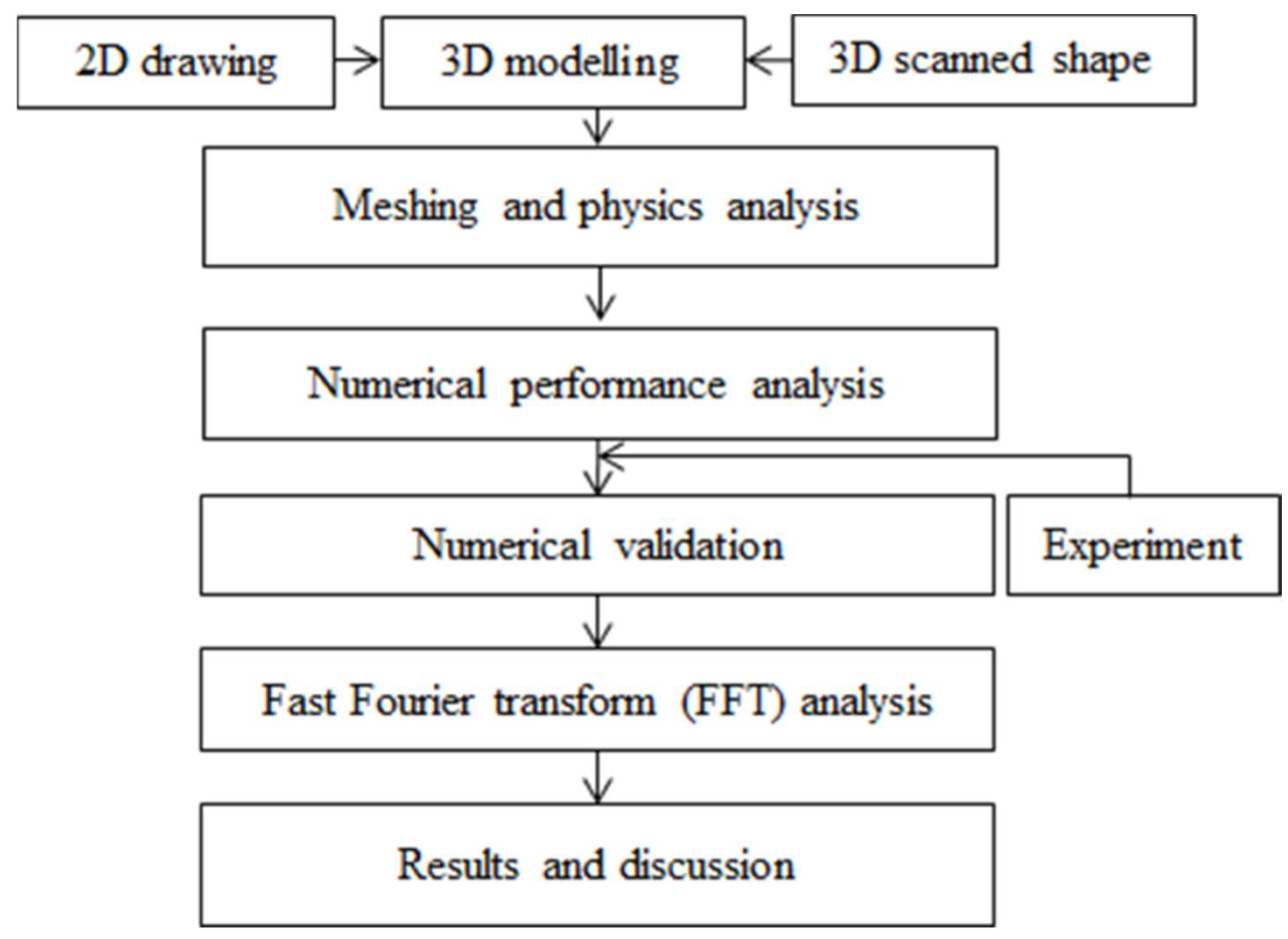
2. Numerical Analysis

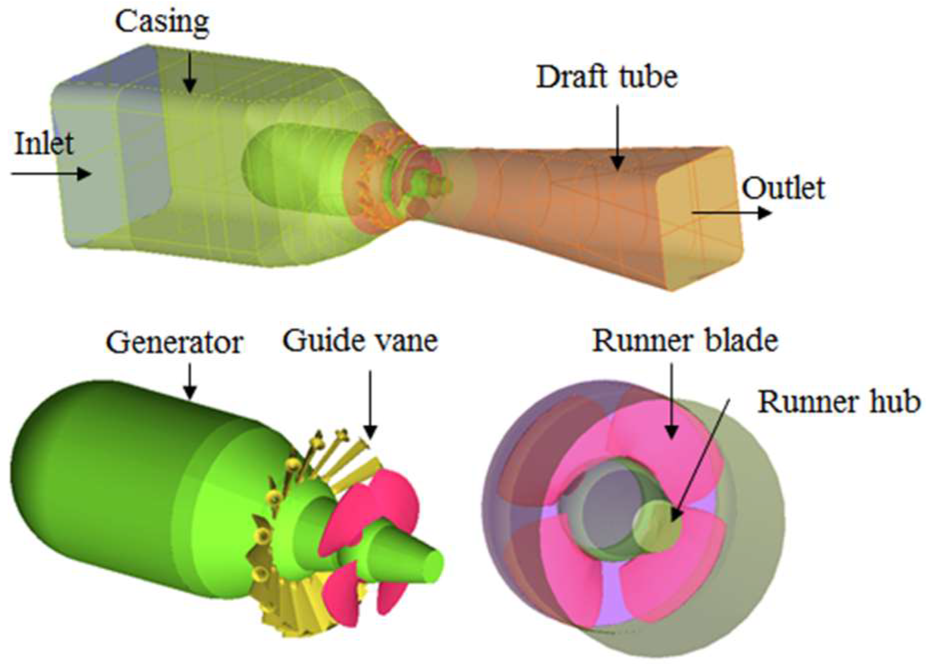
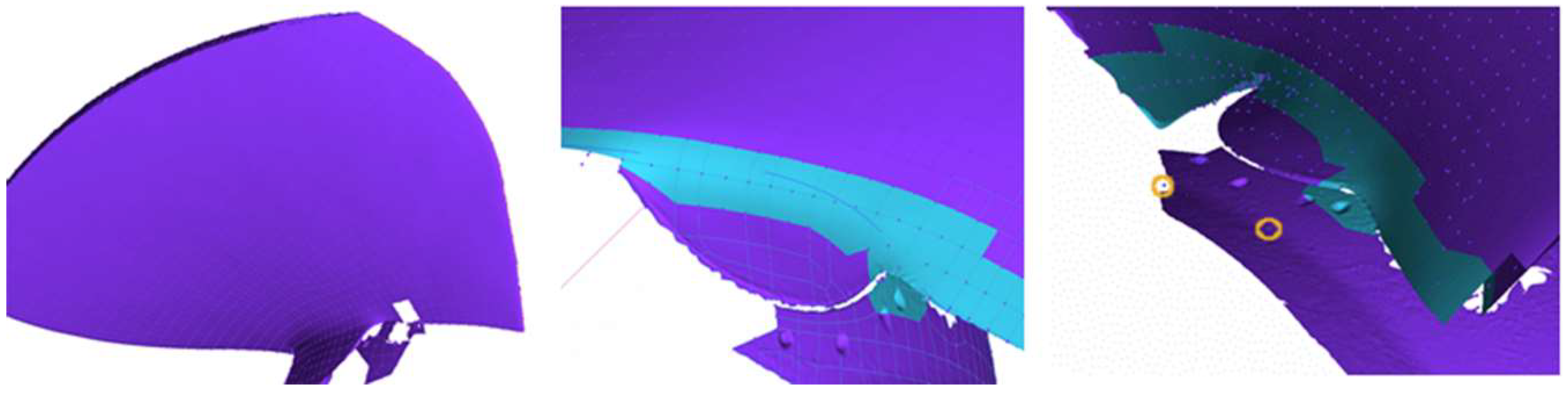
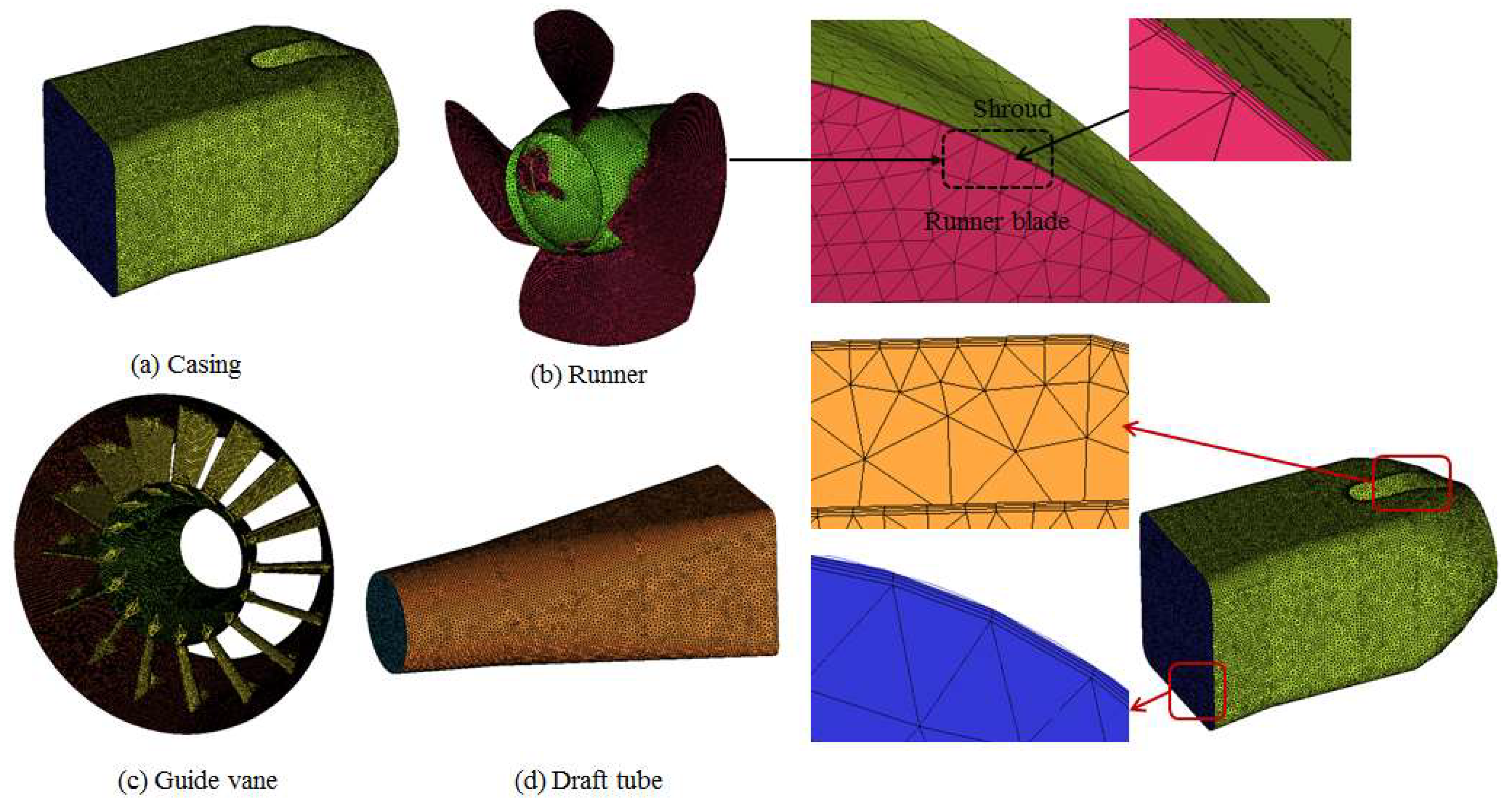
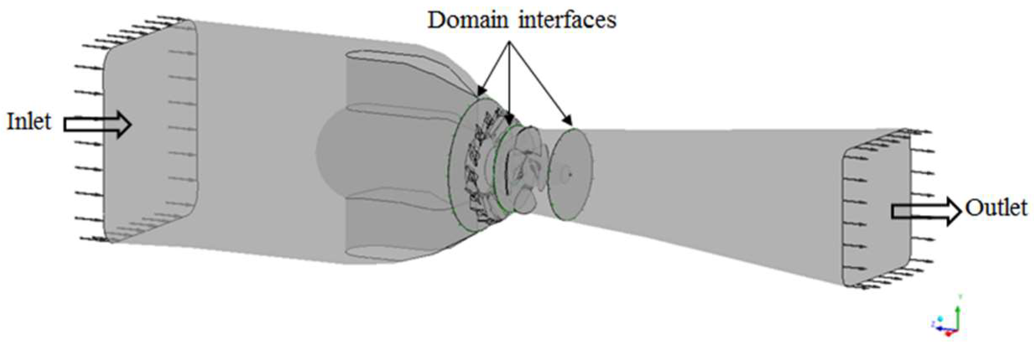
2.1. Geometrical Model and Meshing

The 3D geometry of the horizontal prototype Kaplan turbine was selected to analyze the flow characteristics of the hydrological aberration as shown in Figure 1. The runner shape was scanned using a noncontact portable 3D scanner from the operation site. During scanning, the 3D scanner generated the 3D geometrical shape of the runner blade through the laser detection technique connected to the computer; however, the 3D runner blade shape generated was not smoothened out, as shown in Figure 2. Therefore, the gaps were filled, and the rough geometry was modified using CAD software ANSYS ICEM to get the original 3D runner shape. The block diagram of the research study is represented in Figure 3.
The 3D geometry of the casing, generator, guide vane, runner hub, and draft tube domains was designed by ICEM-CFX from the 2D drawing information provided by Chungju 2 Hydropower Plant, K-Water, Korea. The original prototype runner geometry is shown in Figure 4. In this study, two model cases (cases 1 and 2) were invested. The tip clearance gap of case 1 was 1.75 mm and 6 mm (only two blades) for case 2. Figure 5 shows the tip gap between the runner and runner chamber (adopted from K-Water). In this figure, A, B, and C represent the gap height between the runner and the runner housing. The tip gap of A was 6.05 mm, 4.80 mm for B, and 3.35 mm for C. The runner tip clearance was considered the uniform gap, because it is difficult to make the real shape as well as good grid of the runner. Table 1 shows the specifications of the model turbine.
The model turbine was meshed by ANSYS ICEM-CFX (16.2) based on finite volume methods (FVM) [29]. Because of the flexibility of the complex design of the hydraulic turbine when solving complex geometries, the unstructured prism tetrahedron grid system was employed to make the grid. The total meshing grids of case 1 were 3,167,233 nodes and 16,506,970 elements, and 4,937,129 nodes and 27,291,793 elements for case 2. The meshing grids are shown in Figure 6. To precisely simulate the flow in a whole turbine channel, further grid refinement around the blades’ edges is required. In the blade end surfaces, the volumes’ sizes were controlled as shown in Figure 6. Because of the complex prototype geometry, the grid becomes large, which is needed for a comparatively fine grid, as numerical simulations lead to a considerable amount of computational data. To reduce the influence of grid number on the computational results, a grid independence test is important to check the convergence of the simulation. The grid independence test was performed at the rated operating condition (GV 67° and RV 23°), and the results found that the efficiency deviation was less than 1% as shown in Figure 7. The mesh independence test was carried out based on the most accepted grid convergence index (GCI) method [30,31,32]. With this, the approximate and extrapolated relative errors can be expressed as:
ε a = | ε n e w ε o l d ε n e w | 100 %
The grid convergence index (GCI) can be written as:
G C I = 1.25 × ε a r 2 1
where ε a is the relative error, and r is the mesh ratio.
The finite volume approaches of the cells near the wall boundary are irregular, thus possibly requiring a particular treatment. Prisms can first create a layer of regular prisms near the wall and then mesh the remaining volume with tetrahedrons [33,34]. This grid approach enhances the near walls and gives better solutions and convergence of computational methods [33].
The quality of the model turbine grids is represented in Table 2. The estimated numerical uncertainties in the hydraulic turbine are shown in the Table 3. From the table, the 3,167,233 grid density showed lower uncertainties. Also, the total meshed element and nodes were different for each guide vane and runner vane opening angle as represented in Table 4 and Table 5 for cases 1 and 2, respectively.

2.2. Governing Equations

Numerical analysis of the fluid flow was based on the continuity and momentum equations [25,35], which are expressed as Equations (3) and (4) as follows, respectively:
u i x i = 0
ρ ( u i t + u j u i x j ) = p x i + x j ( μ u i x j ρ u i u j ¯ )
where ρ and μ are density and dynamic viscosity respectively, p is the pressure scalar, ρ u i u j ¯ is the apparent turbulent stress tensor.
For numerical simulation, the turbine domain was considered with its steady-state, incompressible flow. The runner domain was rotating on the z-axis at a given rotating speed, and the casing and draft tube were on a stationary domain. The turbine domain is shown in Figure 8. The analysis boundaries were imposed on the inlet and the outlet as static pressure of 90,221 Pa and 0 Pa on each domain model. All boundary walls were assumed to be smooth with a nonslip condition. A frozen rotor was applied to couple the rotation and stationary domain for steady analysis. The rotational speed was 171.4 rpm. Menter’s shear stress transport (SST) turbulence model was used to solve the turbulence behavior of the flowing fluid [36,37]. The residual value was of 1 × 10⁵ was controlled by convection criteria. The unsteady simulation was carried out to investigate the dynamic behavior of the model Kaplan turbine. The time step of the 3° rotation of the runner blade was selected. In general, 4–5 cycles would be enough to get the stable unsteady flow, but because of the limitation of computer resources, two rotation cycles were made for case 1, and five cycles for case 2. Therefore, the time step was 7.29 × 10⁻³ s. The total time for case 1 was 0.70 s, and 1.75 s for case 2. The transient stator–rotor was accounted to couple the rotation and stationary interface for the unsteady analysis. Furthermore, the FFT analysis of the Kaplan turbine investigated the stability of the operating conditions.

2.3. Calculation of Hydraulic Performance

The hydraulic performance of the Kaplan turbine was calculated using three parameters, namely the head, power, and efficiency of the hydraulic turbine [1]. Based on the simulation results, the performance of the Kaplan turbine can be estimated. The hydraulic head is calculated from the measured pressure, fluid velocity, and elevation at the inlet and outlet measuring sections. The hydraulic head is defined as:
H = ( p ρ g + v 2 2 g + z ) 1 ( p ρ g + v 2 2 g + z ) 2
Hydraulic power is Ls and obtained as the rate of the mechanical energy removal from the flowing fluid stream; it is defined as:
L w = ρ Q g H
The flow rate Q across any face S can be expressed as
Q = V S = i = 1 n V n i S i
where n is the number of the cells, Vni is the calculated individual velocity along the face normal vector, and Si is the area of a face cell. As the neglecting friction and torque generated by pressure changes in turbomachinery, the shaft power Ls of the hydraulic machine is defined as:
L s = ω T s h a f t
where ω is the angular speed of the runner, and Tshaft is the torque of the machine shaft. Lastly, the efficiency, η t of the turbine is expressed as:
η t = L s L w = ω T s h a f t ρ Q g H
where ρ is the density of water, g is the gravitational acceleration, and H is the turbine working head.

3. Results and Discussion

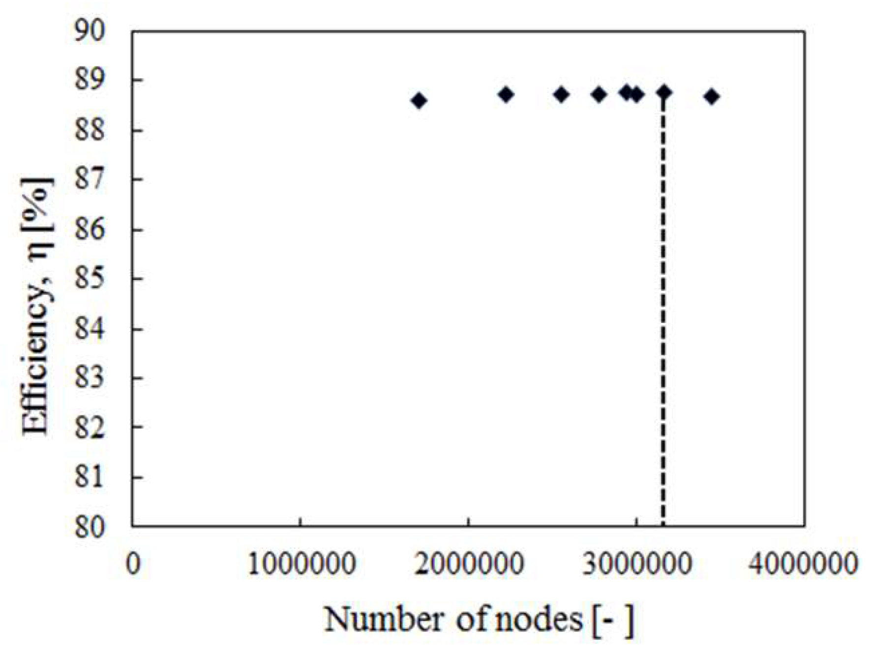
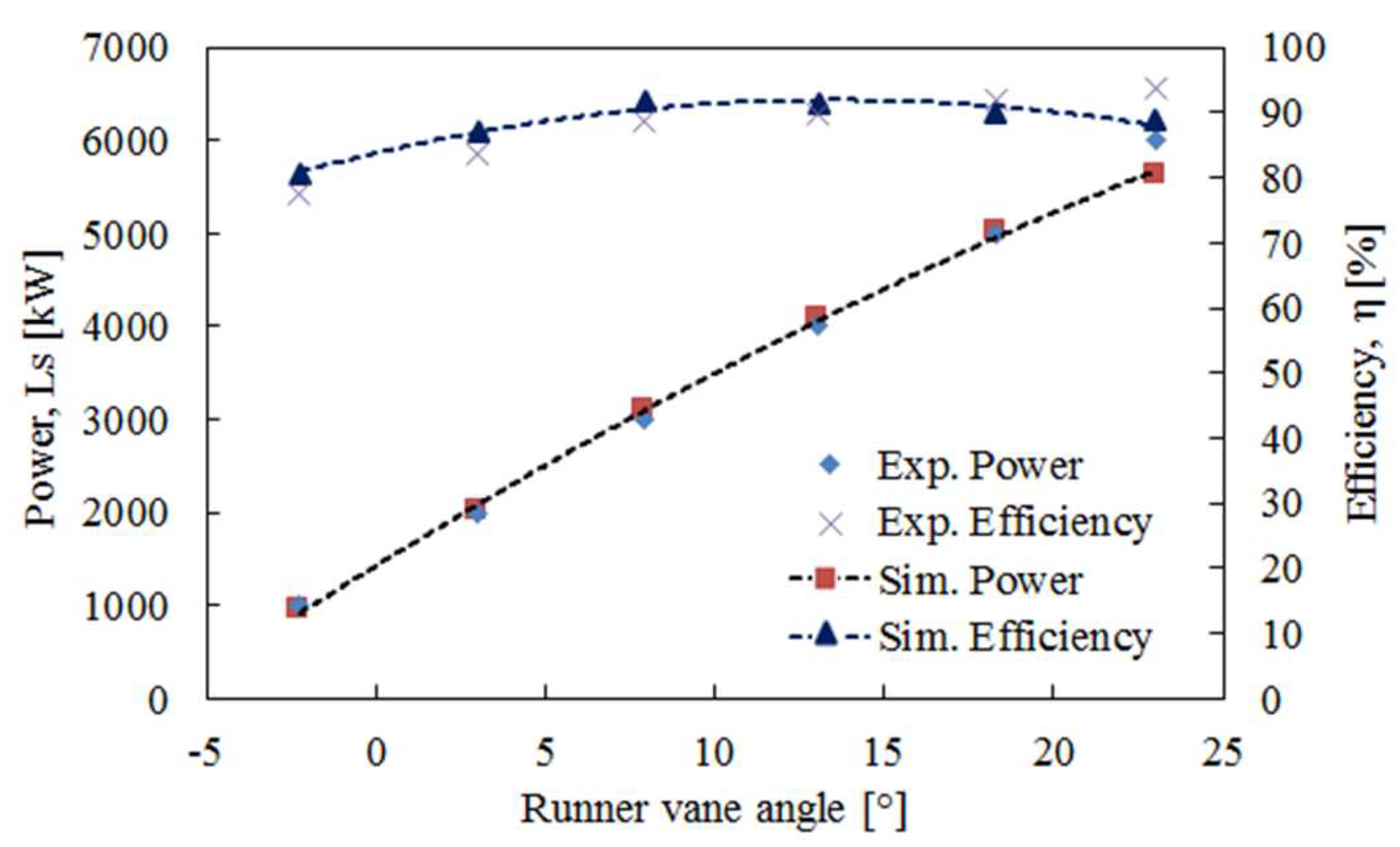
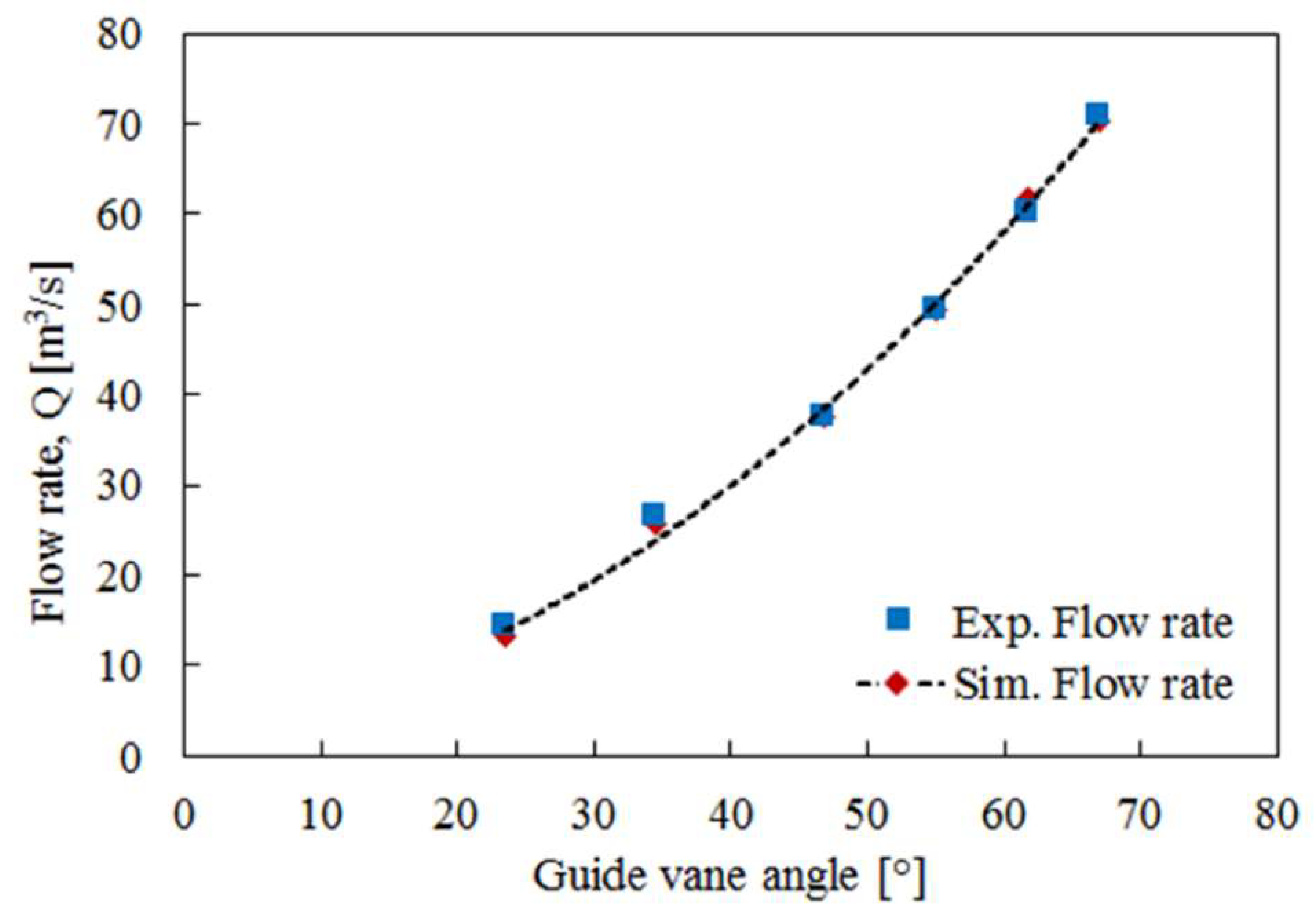
3.1. Validation of Numerical Results

To confirm the numerical results, simulation results were validated with experimental data. Figure 9 and Figure 10 show the comparison of the experiment and the numerical values at different operating conditions for the tip clearance interval of 1.75 mm. It is seen from that figure that both results had almost similar trends. Therefore, it was revealed that the results of the computer simulations agree with the experimental results.

3.2. Performance Characteristics

Computer simulations were conducted at different flow rates by changing guide vane and runner vane opening angles of the Kaplan turbine for cases 1 and 2. The guide vane opening angles varied from 23.5° to 72.0°, and the runner vane opening angles varied from −4° to 25° for cases 1 and 2. The simulations were conducted with output ranging from 1000 to 6000 kW. Figure 11 shows the runner vane angle versus efficiency and runner vane angle versus power performance characteristics of the CFD results of the Kaplan turbine for cases 1 and 2. From the graph, at the rated operating condition for case 1, the efficiency was found as 88.72%, and power was 5.64 MW at a flow rate of 70.39 m3/s; however, for case 2, the efficiency was only 84.06%, and power was 5.59 MW at a flow rate of 74.31 m3/s. It was expected to get the desired output at the rated condition of 6 MW, but the computed power was slightly less than 6 MW. It is also seen that the output difference was only 0.69%. Figure 12 shows the guide vane angle efficiency and versus flow rate performance characteristics of the CFD results for cases 1 and 2. It is seen from Figure 12 that the average deviation of the flow rate was only 1.46%. On top of this, the average efficiency was only 1.54%. In the case of efficiency at the rated condition, the difference was only 4.59% as shown in Figure 11 and Figure 12.

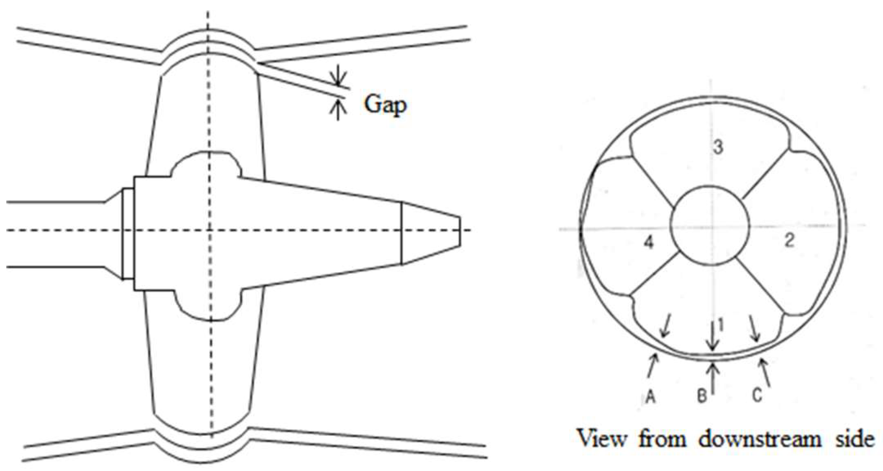
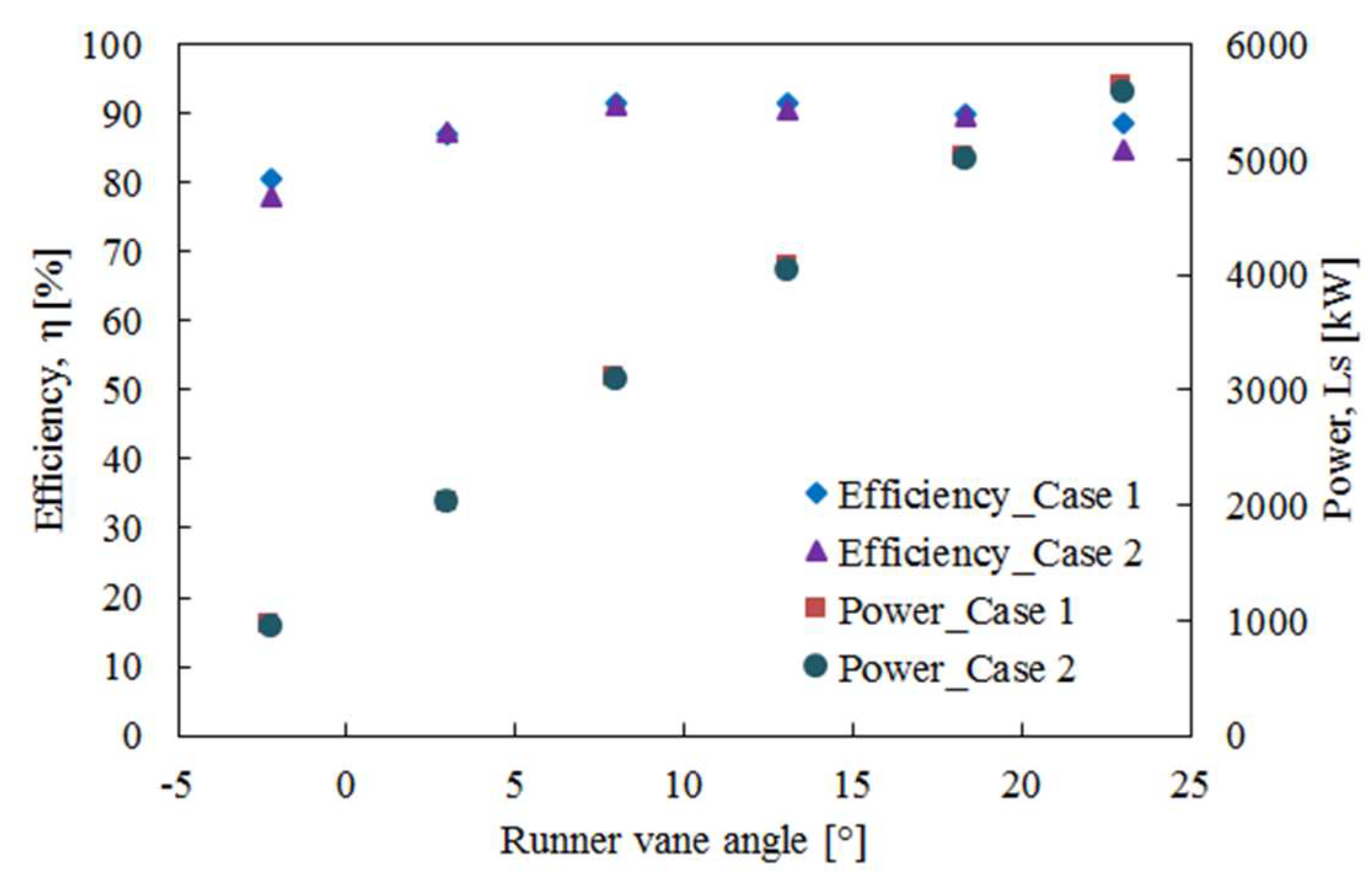
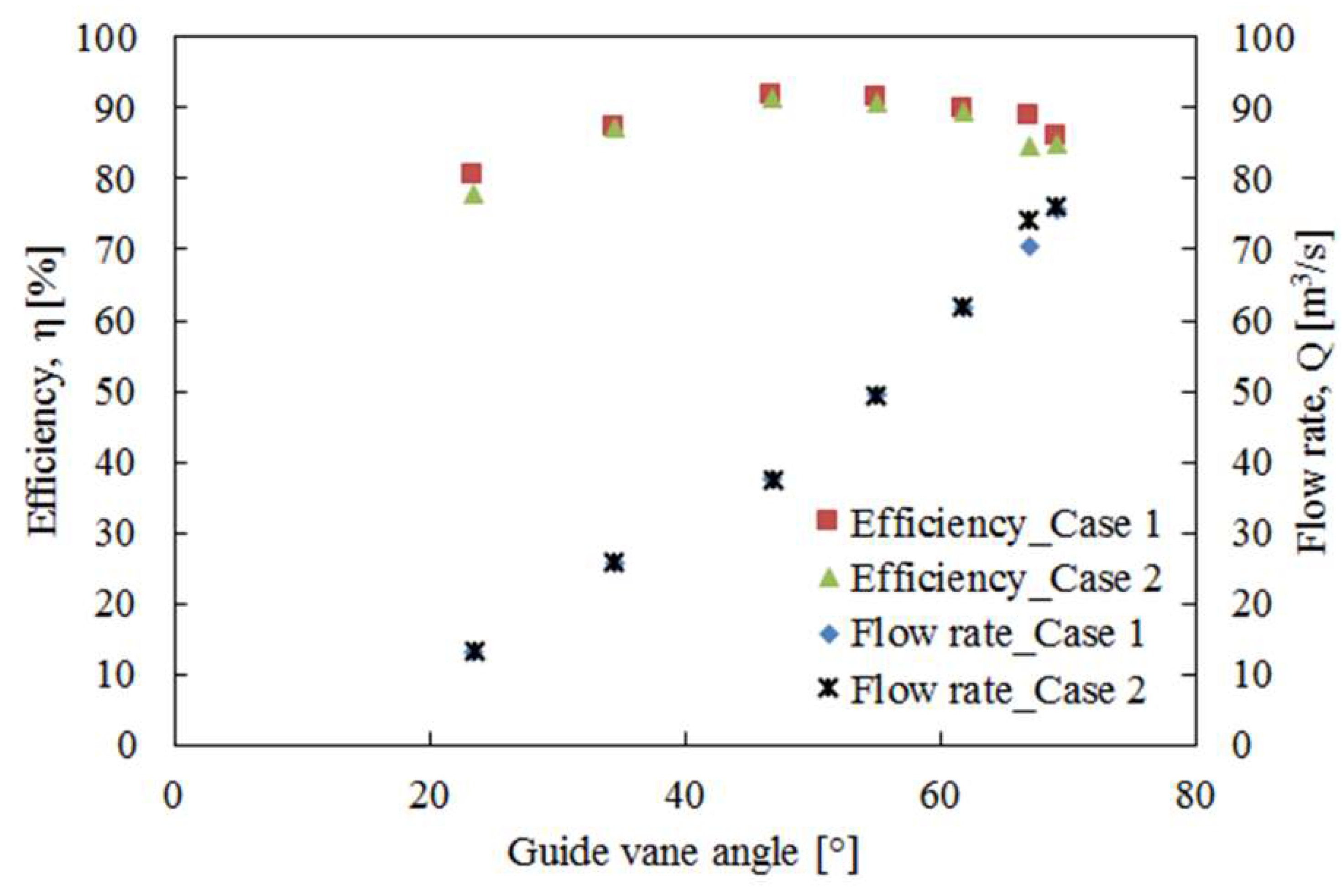
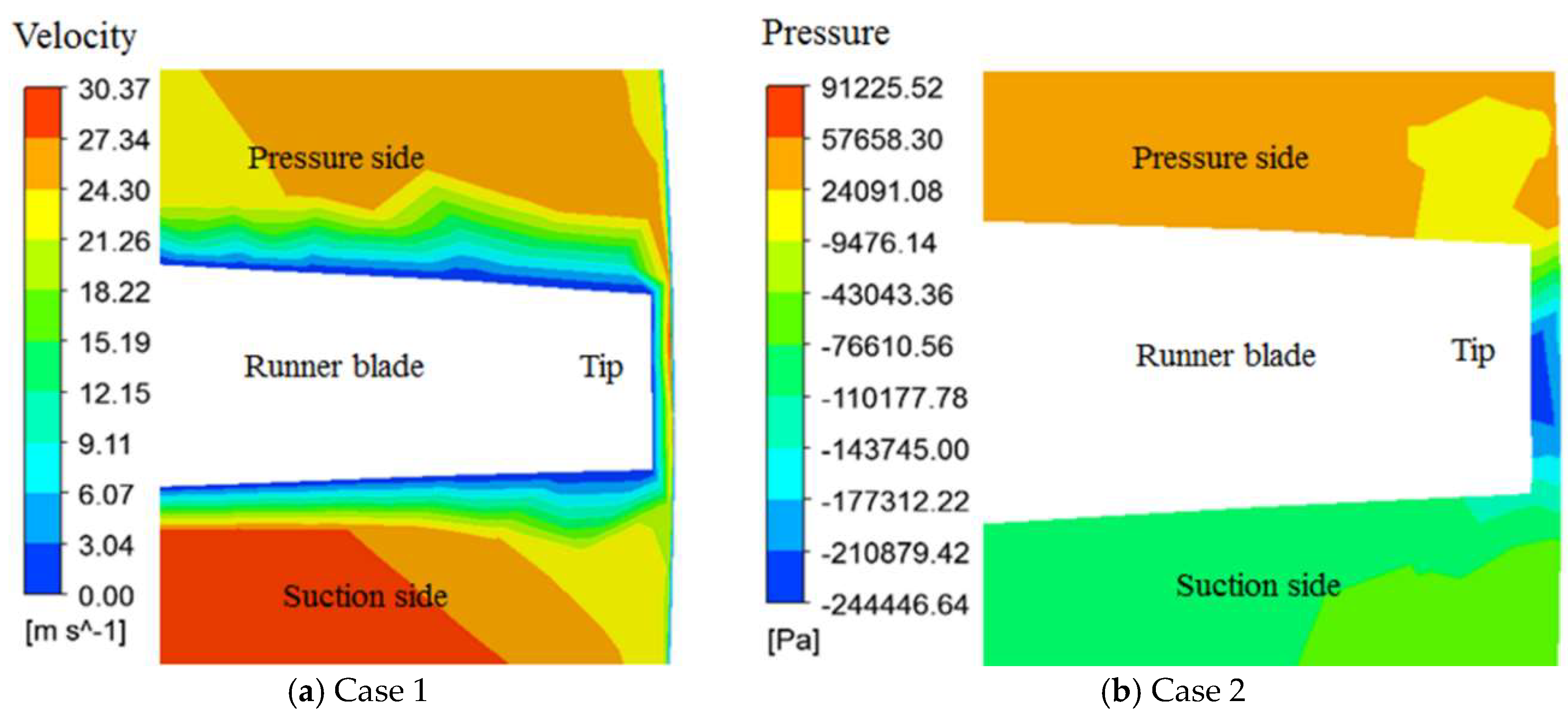
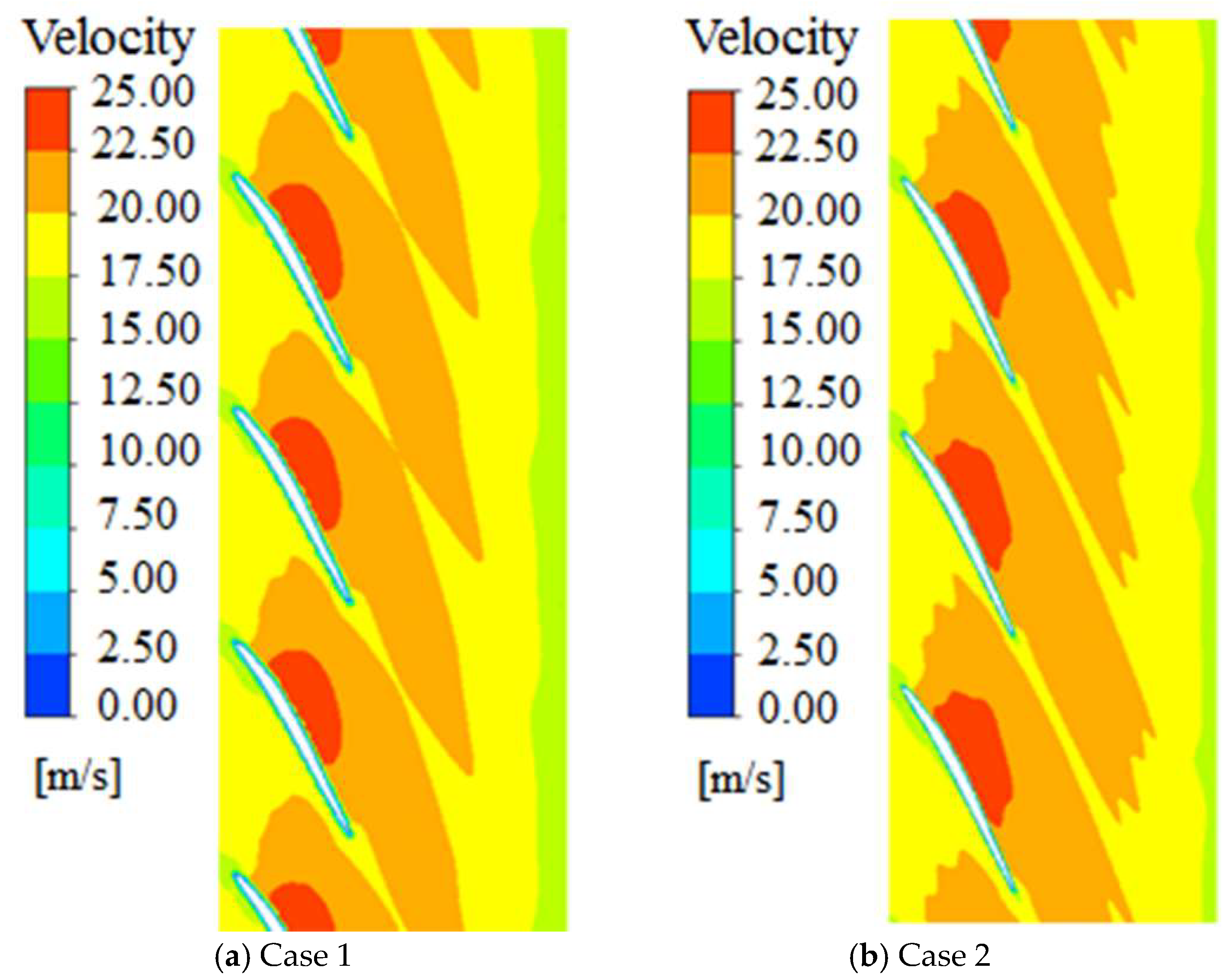
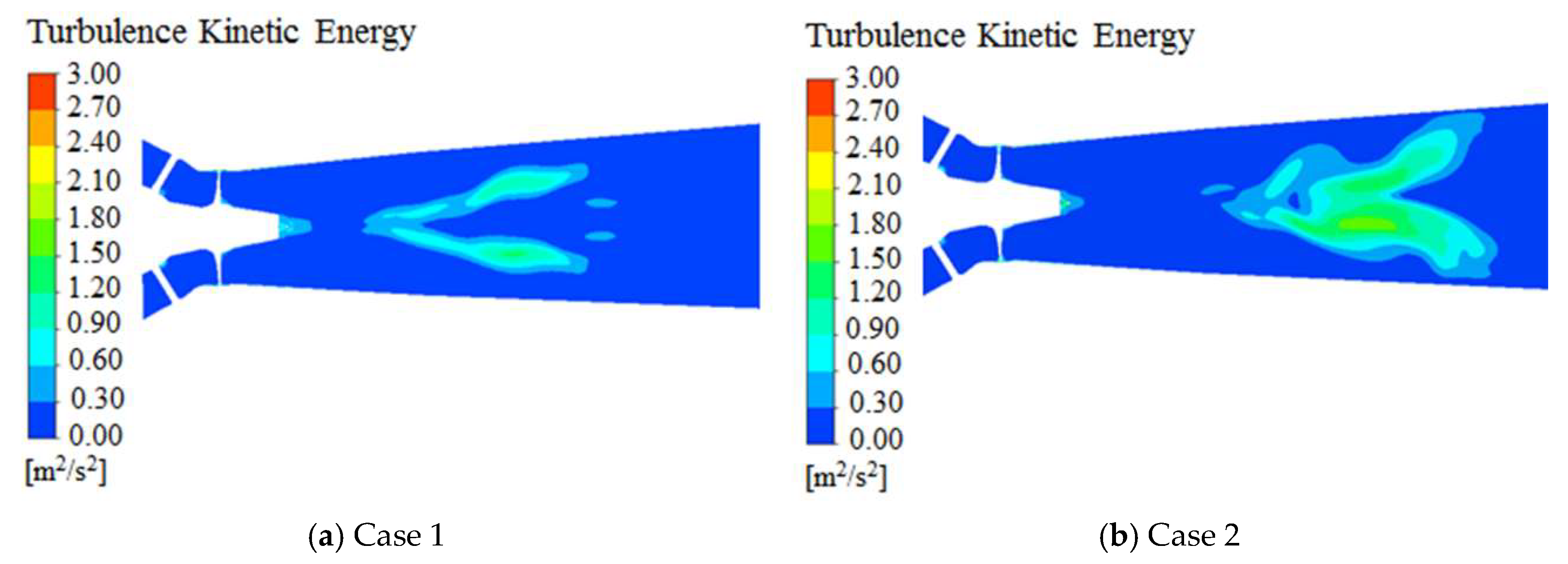
3.3. Effect of Tip Clearance

The analysis of the internal flow characteristics was performed at the rated condition (GV 67° and RV 23°), which is mostly operated during power generation. Tip clearance flow creates a vortex that separates from the runner blade suction side and gives rise to a local pressure reduction near the tip on the suction side of the runner blade and at the center of the tip vortex. In this region, if the static pressure falls below the vapor pressure of the liquid water flowing through the turbine, then cavitation will occur. Figure 13 shows the tip clearance velocity and pressure profiles distribution in a plane view. It is observed that the tip clearance vortex impacts on the shroud of the runner, where pressure suddenly drops into the center of the runner; here, pressure is gradually increased, and velocity is decreased near the runner blade trailing edge. In this case, a possible cavitation scenario could be formed inside the tip vortex [13].
Figure 14 shows the blade-to-blade velocity contour for the models for cases 1 and 2 at rated conditions; here, for case 1, the flow velocities inside the turbine are well predicted. No recirculation zone was found inside the runner and shroud tip gap. However, for case 2, the flow instability occurred near the tip of the runner, velocity is increased at the center of the runner suction side, and the flow is highly unsteady. Moreover, the tip clearance gap increases the turbulent kinetic energy and reduces the output of the turbine. Figure 15 shows the turbulent kinetic energy in the vicinity of the draft tube of cases 1 and 2 at a rated condition. It was observed that for case 1, the turbulent kinetic energy at the exit of the runner outlet was symmetrical in the up and down directions, and for case 2, it was asymmetric, which may be because of the instability of the flow near the uneven tip gap of the runner.

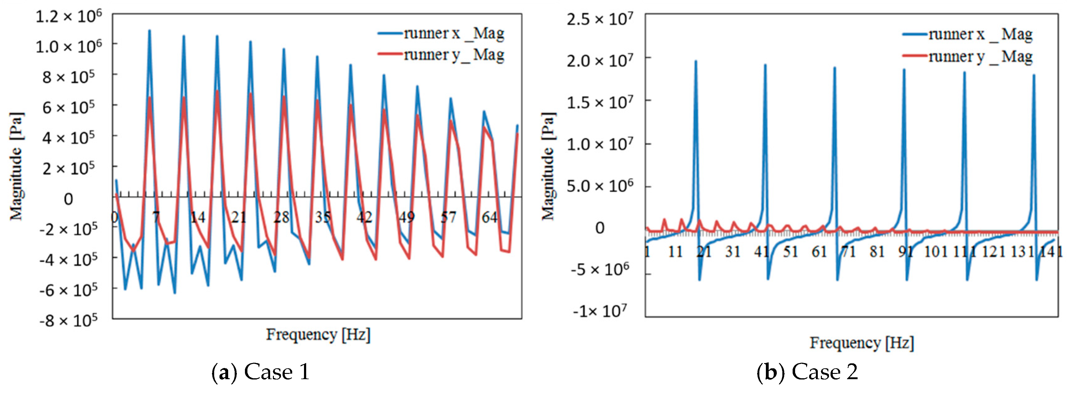
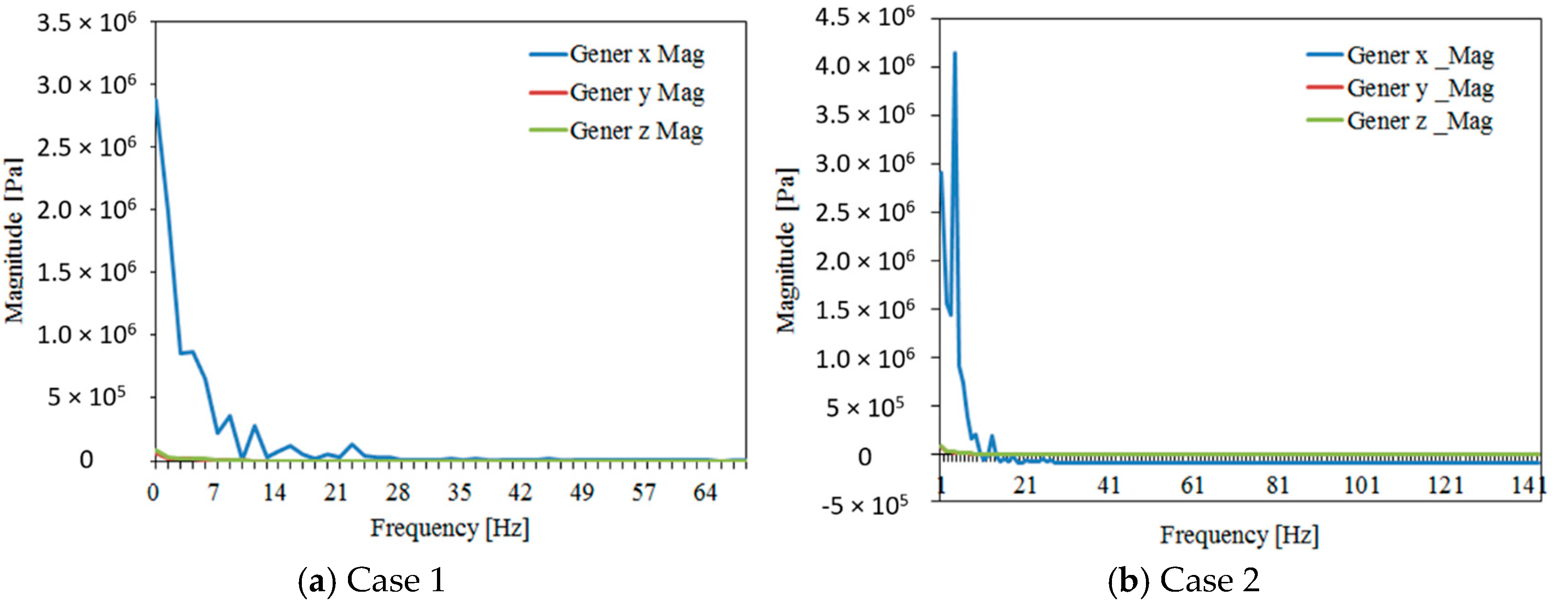
3.4. Pressure Pulsation Analysis

For an unsteady flow analysis, the flow simulation was determined as 69.1° for the guide vane, 25° for the runner vane, and 8.5 m for the head. This was done to investigate the phenomenon in which the output of the guide vane does not increase appropriately even if the drop of the actual vane is lower than the rated value during operation of the Kaplan turbine. Because the unsteady flow causes vibration to a large extent, the pressure pulsation analysis near the runner and the generator was analyzed using FFT. The x-, y-, and z-axes are x, y, and z, respectively. As a result of the analysis, the pressure variation of the runner vane of the standard Kaplan turbine is similar to the x in the horizontal direction and the y in the vertical direction within 1.5 times, and the maximum size level is 106 as shown in Figure 16a. Figure 16b shows the pressure pulsation results near the Kaplan turbine runner at unsteady intervals. Having an increased tip gap of unsteady flow, the oscillations on the horizontal axis are more than 10 times greater than the vertical axis, which is 10 times more than the normal Kaplan turbine pressure pulsations. For measuring the frequency of the generator, it was found that the pressure fluctuations generated by the generator were not significantly different from the pressure fluctuations of the vertical axis to the horizontal axis in the direction of the axial runner as shown in Figure 17a. As shown in Figure 17b, the pressure fluctuation occurs in the same cycle as the pressure fluctuation period of 6–7 Hz occurring in the runner vane. It was considered that the vibration caused by the unbalance flow of the runner vane of the tip gap of Kaplan turbine was transmitted to the generator.

4. Conclusions

This study was based on the steady and unsteady flow analyses with varying tip gaps between the runner and the discharge ring of the Kaplan turbine through a computerized flow analysis. For numerical analysis, three-dimensional modeling of the existing Kaplan turbine was performed from the drawing and scanning shape data. The performance analysis of the existing turbine was accomplished by changing the runner vane opening from −4° to 25° and the guide vane opening from 23.5° to 72.0°. The computed results were compared with the experimental data provided by the manufacturer to verify the validity of the simulation. The performance of the standard tip gap (1.75 mm) and that of an abnormal tip gap (6 mm) of the Kaplan turbines were also compared. It was confirmed that the output of the turbine decreased when the interval was generated. In the comparison of the results, in both cases, the flow rate of case 2 was 1.46% less than of the conventional turbine, and the output difference was a maximum of 81 kW. In the case of efficiency, the difference between both cases was only 4.59% within the rated range. The internal flow field and the turbulent kinetic energy distribution was also observed and found that unsteady flow occurred as the gap became higher than usual, and pressure fluctuation and period were confirmed at the peripheral part of the vane. Through the FFT analysis, it was confirmed that the vibration caused by the flow instability of the runner vane was transmitted to the generator. To reduce the dynamic vibration effect of the turbine, the tip gap of the machine should be minimized. Therefore, repairing the runner and discharge ring gap within the normal range should be considered because this flow may cause severe vibrations to the runner. The study notes that the simulation results did not consider the bearing and mechanical loss of the turbine that occurred in the machine. The thrust bearing, shaft seals, and guide bearings into the model could be a great interest for further research combined with the FFT analysis.

Author Contributions

H.-H.K. contributed in result analyses and edited the draft, M.R. conceived, analyzed the results and wrote the paper; K.K. designed the turbine domain; S.-H.S. contributed in fund collection and reviewed the work continuously.

Funding

The research was funded by Korea Institute of Energy Technology Evaluation and Planning grant number 20153030071530.

Acknowledgments

This research was supported by the Korea Institute of Energy Technology Evaluation and Planning (KETEP). The grant number is 20153030071530 for the Promotion of Science.

Conflicts of Interest

The authors declare no conflict of interest.

Nomenclature

CFDComputational Fluid dynamics
FFTFast Fourier Transformation
GCIGrid convergence index
gAcceleration due to gravity, m/s2
HHead, m
LsShaft power, kW
pPressure, Pa
QFlow rate, m3/s
rMesh ratio
SiArea of a face cell
TshaftTorque, N·m
tTime, s
u i Velocity vector, m/s
vVelocity of fluid, m/s
VniVelocity along the face normal vector
xComponent of position vector, m
zElevation of water level, m
Greek Symbols
ρDensity, kg/m3
η t Turbine efficiency, %
ωAngular velocity, rad/s
μViscosity, Pa·s
Subscript
i, jTensor indices
1, 2Inlet, outlet

References

  1. Fox, R.W.; Mcdonald, A.T.; Pritchard, P.J.; Leylegain, J.C. Fluid Mechanics, 8th ed.; John Wiley and Sons, Inc.: Hoboken, NJ, USA, 2012. [Google Scholar]
  2. Wu, H.; Feng, J.J.; Wu, G.K.; Luo, X.Q. Numerical investigation of hub clearance flow in a Kaplan turbine. IOP Conf. Ser. Earth Environ. Sci. 2012, 15, 072026. [Google Scholar] [CrossRef] [Green Version]
  3. Roussopoulos, K.; Monkewitz, P.A. Measurements of Tip Vortex Characteristics and the Effect of an Anti-Cavitation Lip on a Model Kaplan Turbine Blade. Flow Turbul. Combust. 2000, 64, 119–144. [Google Scholar] [CrossRef]
  4. Chen, G.T.; Greitzer, E.M.; Tan, C.S.; Marble, F.E. Similarity analysis of compressor tip clearance flow structure. ASME J. Turbomach. 1991, 113, 260–269. [Google Scholar] [CrossRef]
  5. Song, S.J.; Martinez-Sanchez, M. Rotordynamic effects due to turbine leakage flow: Part I, Blade scale effects. ASME J. Turbomach. 1997, 119, 695–703. [Google Scholar]
  6. Storer, J.A.; Cumpsty, N.A. Tip leakage flow in axial compressors. ASME J. Turbomach. 1991, 113, 252–259. [Google Scholar] [CrossRef]
  7. Heyes, F.J.G.; Hodson, H.P. Measurement and prediction of tip clearance flow in linear turbine cascades. ASME J. Turbomach. 1993, 115, 376–382, 698. [Google Scholar] [CrossRef]
  8. Murayama, M.; Yoshida, Y.; Tsujimoto, Y. Unsteady Tip Leakage Vortex Cavitation Originating From the Tip Clearance of an Oscillating Hydrofoil. ASME J. Fluids Eng. 2006, 128, 421–429. [Google Scholar] [CrossRef]
  9. Cojocaru, V.; Balint, D.; Campian, C.V.; Nedelcu, D.; Jianu, C. Numerical Investigations of Flow on the Kaplan Turbine Runner Blade Anticavitation Lip with Modified Cross Section, Recent Researches in Mechanics. In Proceedings of the 2nd International Conference on Theoretical and Applied Mechanics 2011 (TAM ‘11), Corfu Island, Greece, 14–16 July 2011; pp. 215–218. [Google Scholar]
  10. Hutton, S.P. Component Losses in Kaplan Turbines and the Prediction of Efficiency from Model Tests. Proc. Inst. Mech. Eng. 1954, 168, 743–762. [Google Scholar] [CrossRef]
  11. Laborde, R.; Chantrel, P.; Mory, M. Tip Clearance and Tip Vortex Cavitation in Axial Flow Pump. ASME J. Fluids Eng. 1997, 119, 680–685. [Google Scholar] [CrossRef]
  12. Tallman, J.J.; Lakshminarayana, B.B. Numerical Simulation of Tip Leakage Flows in Axial Flow Turbines, With Emphasis on Flow Physics: Part I—Effect of Tip Clearance Height. ASME J. Turbomach. 2000, 123, 314–323. [Google Scholar] [CrossRef]
  13. Nilsson, H.; Davidson, L. Validations of CFD against detailed velocity and pressure measurements in water turbine runner flow. Int. J. Numer. Methods Fluids 2003, 41, 863–879. [Google Scholar] [CrossRef]
  14. Gehrer, A.; Schmidl, R.; Sadnik, D. Kaplan turbine runner optimization by numerical flow simulation (CFD) and an evolutionary algorithm. In Proceedings of the 23rd IAHR Symposium on Hydraulic Machinery and Systems, Yokohama, Japan, 17–21 October 2006. [Google Scholar]
  15. Bodkhe, R.G.; Nandurkar, Y.Y.; Akant, S.S.; Banker, S.L. Experimental analysis on Kaplan turbine to determine performance characteristics curve at part load conditions. Int. J. Res. Eng. Applied Sci. 2015, 3, 37–41. [Google Scholar]
  16. Anup, K.C.; Thapa, B.; Lee, Y.-H. Transient numerical analysis of rotor–stator interaction in a Francis turbine. Renew. Energy 2014, 65, 227–235. [Google Scholar]
  17. Wang, F.J.; Li, X.Q.; MA, J.M.; Yang, M. Experimental investigation of characteristic frequency in unsteady hydraulic behaviour of a large hydraulic turbine. J. Hydrodyn. 2009, 21, 12–19. [Google Scholar] [CrossRef]
  18. Su, W.T.; Li, X.B.; Lan, C.F.; Ah, S.; Wang, J.S.; Li, F.C. Chaotic dynamic characteristics of pressure fluctuation signals in hydro-turbine. J. Mech. Sci. Technol. 2016, 30, 5009–5017. [Google Scholar] [CrossRef]
  19. Glowacz, A. Fault diagnosis of single-phase induction motor based on acoustic signals. Mech. Syst. Signal Process. 2018, 117, 65–80. [Google Scholar] [CrossRef]
  20. Glowacz, A. Acoustic-based fault diagnosis of commutator motor. Electronics 2018, 7, 299. [Google Scholar] [CrossRef]
  21. Fei, S.-W. Fault Diagnosis of Bearing by Utilizing LWT-SPSR-SVD-Based RVM with Binary Gravitational Search Algorithm. Shock Vib. 2018, 2018, 1–8. [Google Scholar] [CrossRef]
  22. Caesarendra, W.; Tjahjowidodo, T. A Review of Feature Extraction Methods in Vibration-Based Condition Monitoring and Its Application for Degradation Trend Estimation of Low-Speed Slew Bearing. Machines 2017, 5, 21. [Google Scholar] [CrossRef]
  23. Wu, Y.; Liu, S.; Dou, H.-S.; Wu, S.; Chen, T. Numerical prediction and similarity study of pressure fluctuation in a prototype Kaplan turbine and the model turbine. Comput. Fluids 2012, 56, 128–142. [Google Scholar] [CrossRef]
  24. Rivetti, A.; Lucino, C.; Liscia, S.; Muguerza, D.; Avellan, F. Pressure pulsation in Kaplan turbines: Prototype- CFD comparison. IOP Conf. Ser. Earth Environ. Sci. 2012, 15, 062035. [Google Scholar] [CrossRef]
  25. Drtina, P.; Sallaberger, M. Hydraulic turbines—Basic principles and state-of-the art computational fluid dynamics applications. Proc. Inst. Mech. Eng. Part C. 1999, 213, 85–102. [Google Scholar] [CrossRef]
  26. Zhou, L.J.; Wang, Z.; Xiao, R.; Luo, Y. Analysis of dynamic stresses in Kaplan turbine blades. Eng. Comput. 2007, 24, 753–762. [Google Scholar] [CrossRef]
  27. Onoda, T.; Ito, N.; Hironobu, Y. Unusual condition monitoring based on support vector machines for hydroelectric power plants. In Proceedings of the IEEE Congress on Evolutionary Computation, Hong Kong, China, 1–6 June 2008. [Google Scholar]
  28. Vázquez, J.A.; Cloud, C.H.; Eizember, R.J. Simplified modal analysis for the plant machinery engineer. In Proceedings of the Asia Turbomachinery and Pump Symp., Marina Bay Sands, Singapore, 22–25 February 2016. [Google Scholar]
  29. Ansys Inc. ANSYS-CFX (CFX Introduction, CFX Reference Guide, CFX Tutorials, CFX-Pre User’s Guide, CFX-Solver Manager User’s Guide, Theory Guide); Release 16.00; Ansys Inc.: Cannonsburg, PA, USA, 2016. [Google Scholar]
  30. Trivedi, C.; Cervantes, M.J.; Gandhi, B.K.; Dahlhaug, O.G. Experimental and Numerical Studies for a High Head Francis Turbine at Several Operating Points. ASME J. Fluids Eng. 2013, 135, 111102. [Google Scholar] [CrossRef]
  31. Bergstrom, J.; Gebart, R. Estimation of Numerical Accuracy for the Flow Field in a Draft Tube. Int. J. Num. Meth. Heat Fluid Flow 1999, 9, 472–486. [Google Scholar] [CrossRef]
  32. Celik, I.B.; Ghia, U.; Roache, P.J.; Freitas, C.J.; Coleman, H.; Raad, P.E. Procedure for Estimation and Reporting of Uncertainty due to Discretization in CFD Applications. ASME J. Fluids Eng. 2008, 130, 078001. [Google Scholar]
  33. Friziger, J.H.; Peric, M. Computational Methods for Fluid Dynamics, 3rd ed.; Springer: New York, NY, USA, 2002. [Google Scholar]
  34. Choi, H.J.; Zullah, M.A.; Roh, H.W.; Ha, P.S.; Oh, S.Y.; Lee, Y.H. CFD validation of performance improvement of a 500 kW Francis turbine. Renew. Energy 2013, 54, 111–123. [Google Scholar] [CrossRef]
  35. Georgiadis, N.J.; Yoder, D.A.; Engblorn, W.B. Evaluation of modified two-equation turbulence models for jet flow predictions. AIAA J. 2006, 44, 3107–3114. [Google Scholar] [CrossRef]
  36. Wilcox, D.C. Turbulence Modeling for CFD, 1st ed.; DCW Industries, Inc.: La Cañada Flintridge, CA, USA, 1994. [Google Scholar]
  37. Menter, F.R. Two-Equation Eddy-Viscosity Turbulence Models for Engineering Applications. AIAA J. 1994, 32, 1598–1605. [Google Scholar] [CrossRef]
Figure 1. 3D geometry of the prototype Kaplan turbine.
Energies 12 00264 g001
Figure 2. 3D scanned runner blade shape.
Energies 12 00264 g002
Figure 3. The block diagram of the research study.
Energies 12 00264 g003
Figure 4. Runner vane of the Kaplan turbine.
Energies 12 00264 g004
Figure 5. Tip clearance gap of the Kaplan turbine.
Energies 12 00264 g005
Figure 6. 3D unstructured prism grids by parts of the Kaplan turbine.
Energies 12 00264 g006
Figure 7. Mesh independence test of the Kaplan turbine.
Energies 12 00264 g007
Figure 8. Turbine domain for computational analysis.
Energies 12 00264 g008
Figure 9. Comparison between computed and experimental output results as a function of runner vane opening angle.
Energies 12 00264 g009
Figure 10. Comparison between computed and experimental flow rates results as a function of guide vane opening angle.
Energies 12 00264 g010
Figure 11. Comparison of runner vane opening performance (cases 1 and 2).
Energies 12 00264 g011
Figure 12. Performance comparison according to guide vane opening (cases 1 and 2).
Energies 12 00264 g012
Figure 13. Tip clearance (a) velocity and (b) pressure profiles between the runner blade and the shroud (case 2).
Energies 12 00264 g013
Figure 14. Blade-to-blade velocity contours of the Kaplan turbine.
Energies 12 00264 g014
Figure 15. Distribution of the turbulence kinetic energy at draft tube.
Energies 12 00264 g015
Figure 16. Frequency analysis of runner vane.
Energies 12 00264 g016
Figure 17. Frequency analysis near the generator.
Energies 12 00264 g017
Table 1. Main design parameters of the prototype Kaplan turbine.
DescriptionDimension
Runner outlet diameter1648.25 mm
Head9.2 m
Flow rate75.3 m3/s
Max. Power6000 kW
Rotational speed171.4 rpm
Runner blade4
Guide vane16
Table 2. Mesh quality of the Kaplan turbine.
DescriptionElementsNodesY+
Casing3,495,838694,056~478
Guide vane2,744,459520,788~276
Runner7,054,4231,313,645~597
Draft tube3,212,250638,744~121
Total1,6506,9703,167,233
Table 3. Grid convergence uncertainties in the numerical solutions.
No.NodesGrid Ratio, rEfficiency (%)Error, εaGCI
116988661.3188.6020.117380.2047
222257711.1488.7060.006760.0269
325514481.0888.7120.033820.2359
427705621.1488.7420.007890.0321
531672331.0788.7490.002250.0171
629351780.9788.7470.020280.5708
730026170.8688.7290.031560.1619
Table 4. Grid numbers for different cases (case 1).
No.Guide Vane Angle (°)Runner Vane Angle (°)ElementsNodes
123.5−2.256,292,5741,213,316
234.5311,690,8342,142,607
346.877.958,418,2221,576,519
45513.076,119,6111,185,878
561.8218.36,118,3001,185,676
6672316,506,9703,167,233
768.52311,685,6882,141,639
869.12512,626,3322,305,743
9722512,628,0242,306,005
Table 5. Grid numbers for different cases (case 2).
No.Guide Vane Angle (°)Runner Vane Angle (°)ElementsNodes
123.5−2.2511,109,8622,007,133
234.5342,082,0307,466,191
346.877.958,783,0481,643,035
45513.076,647,4941,281,519
561.8218.314,069,1842,603,090
6672327,291,7934,937,129
768.52312,210,4732,236,618
869.12518,238,1113,309,172
9722518,239,8033,309,434

