Article

Node Temperature of the Coupled High-Low Energy Grade Flus Gas Waste Heat Recovery System

1
School of Energy and Power Engineering, Shandong University, Jinan 250061, China
2
Department of Resources and Civil Engineering, Shandong University of Science and Technology, Tai’an 271019, China
*
Author to whom correspondence should be addressed.
Energies 2019, 12(2), 248; https://doi.org/10.3390/en12020248
Submission received: 27 November 2018 / Revised: 27 December 2018 / Accepted: 11 January 2019 / Published: 15 January 2019
(This article belongs to the Section A: Sustainable Energy)

Abstract

:
Coupled high-low energy grade flus gas waste heat recovery systems (CWHRS) have been applied in power plants to improve unit efficiency. In this study, to evaluate the rationality of waste heat recovery, the energy-grade balance coefficient (EBC) of the CWHRS was derived using the theory of heat balance, exergy balance and energy grade balance. The inlet flue gas temperature (IFT) of the low-temperature economizer was defined as the node temperature of the CWHRS. The optimal node temperature (ONT) was optimal when the absolute value of the EBC was the smallest. The exergy efficiency and EBC of the system installed on a supercritical 600 MW unit were calculated and the result shows that the ONT of the system was about 115 °C, the ONT decreased from about 135 °C to about 113 °C when the IFT increased from 335 °C to 380 °C and the ONT decreased from about 144 °C to about 113 °C when the inlet air temperature increased from −10 °C to 35 °C. The node temperature is recommended as an adjusting parameter of CWHRS to ensure the effect of waste heat recovery.

1. Introduction

About 70% of the generator sets are coal-fired units in China, consuming nearly half of the produced coal every year [1]. The large amounts of coal consumption have caused problems such as shortage of coal resources, greenhouse gas emissions, and environment pollution, etc. Measures to reduce the coal consumption of coal-fired units to overcome these problems are necessary. In general, the heat loss due to exhaust flue gas from power station boilers is about 4–8%, accounting for 40–50% of the total heat loss of the boiler [2]. The design exhaust temperature of the power plant boiler is generally 125–135 °C; however, in actual operation, due to the influence of ash deposition, corrosion and air leakage in the tail of the boiler flue, the exhaust gas temperature is mostly higher than the designed value. According to the statistics, for every 10 °C increase in the exhaust gas temperature, the boiler efficiency decreases 0.6–1.0%, and the standard coal consumption of power generation increases 1.2–2.4 g/(kW·h) [3]. The flue gas waste heat use technology can recover flue gas waste heat to reduce the flue gas temperature to about 80 °C, thus, this technology is an effective measure to reduce the coal consumption of coal-fired units [4].
Many studies have reported the flue gas waste heat use technologies and their impact on coal-fired units. For example, Wang et al. [5,6] used a low temperature economizer (LTE) to heat the condensed water saving the steam extracted from steam turbine, and confirmed the optimal location of the LTE. Huang et al. [7] suggested installing a low pressure economizer (LPE) on a 670 t/h boiler to reduce the flue gas temperature by about 30 °C. Stevanovic et al. [8] proposed adding a high-pressure economizer (HPE) on a 620 MW unit in the Nikola Tesla B thermal power plant, which increased the total efficiency of the unit by 0.53%. Some novel flue gas waste heat use systems were introduced used on the large scale units. Xu et al. [9] suggested use two-stage air preheater and LTE to heat condensed water and inlet air, which saved more high-grade extraction steam for power generation. Huang et al. [10] proposed an improved waste heat use system for power plant boilers based on the traditional bypass flue heat recovery system, in which low-pressure steam is extracted from the low-pressure cylinder to preheat the air, replacing high-temperature flue gas to heat the feed water of the boiler, and the calculation showed the unit’s exergy efficiency was increased to 45.46% on a 1000 MW unit. Liu et al. [11] introduced a coupled high-low energy grade flus gas waste heat recovery system (CWHRS) applied to a 1000 MW double-reheat unit, which has produced good energy-saving effects. All these flue gas waste heat recovery systems were analyzed under the designed condition. However, how to ensure the energy-saving effect of the systems under off-design conditions was not mentioned in the literatures.
Some scholars studied the factors affecting the effect of waste heat use systems and the improved methods. Han et al. [12] optimized a waste heat recovery power generation system in a cement plant using pinch analysis and exergy analysis methods. The optimized system’s power generation increased by 4.96%. Xu et al. [13] applied techno-economic analysis to four waste heat recovery schemes considering heat transfer, thermodynamic, and hydrodynamic factors, and created an optimized system. They stated that heat transfer area and flue gas resistances were the important factors affecting system performance. Espatolero et al. [14,15] compared the boiler efficiency and power generation efficiency under conditions of different condensate access points and different heat exchanger quantities when using flue gas waste heat to heat the condensate and preheat the air, and optimized the flue gas waste heat recovery system. Guo et al. [16] analyzed a waste heat power generation system using the first and second laws of thermodynamics and obtained the optimal operation condition. Butcher [17] studied the effect of pinch point on the performance of a heat recovery steam generator, and the results showed the second law efficiency of the generator decreased with increasing pinch point. Song et al. [18] studied the off-design characteristic of LTE, the LTE has better energy-saving effect under high load. Song et al. [19] quantitatively analyzed energy-saving effect of depth waste heat use system on a 1000 MW units. The result showed coal consumption rate was 3.27 g/(kW·h) under full-load condition, and decreased with the decline of load. Huang et al. [20] built a mathematical model for optimum water flow distribution of LPE to make a unit operate under the highest efficiency. However, little research has studied on how to ensure waste heat recovery effect and rationality under given conditions by adjusting the internal flue gas temperature of the complex waste heat use system.
In the operation of coal-fired units, the exhaust temperature of the boiler changes with the changes in load. In order to prevent low-temperature corrosion on the flue tail heating surface, the final exhaust temperature should not be too low, and the exhaust temperature is generally maintained at about 80 °C [21]. Additionally, the inlet air temperature (IAT) of the boiler needs to be controlled within a reasonable range to ensure the safe and efficient operation of the boiler. Given a determined inlet flue gas temperature (IFT) and outlet exhaust gas temperature of the waste heat use system and IAT of the boiler, it is necessary to find methods of improving the effectiveness of waste heat recovery systems.
In this study, to ensure the rationality of a CWHRS and optimize waste heat recovery under given conditions, we used the theory of heat balance, exergy balance and energy grade balance to analyze a CWHRS. The IFT of the low-temperature economizer was defined as node temperature and used as the adjustment parameter to ensure the effect of waste heat recovery. The optimal node temperature (ONT) was determined by calculating energy-grade balance coefficient (EBC) of a CWHRS installed on a 600 MW unit. The effects of different IFT and IAT on EBC were analyzed to determine the ONT under different conditions.

2. Research Foundation

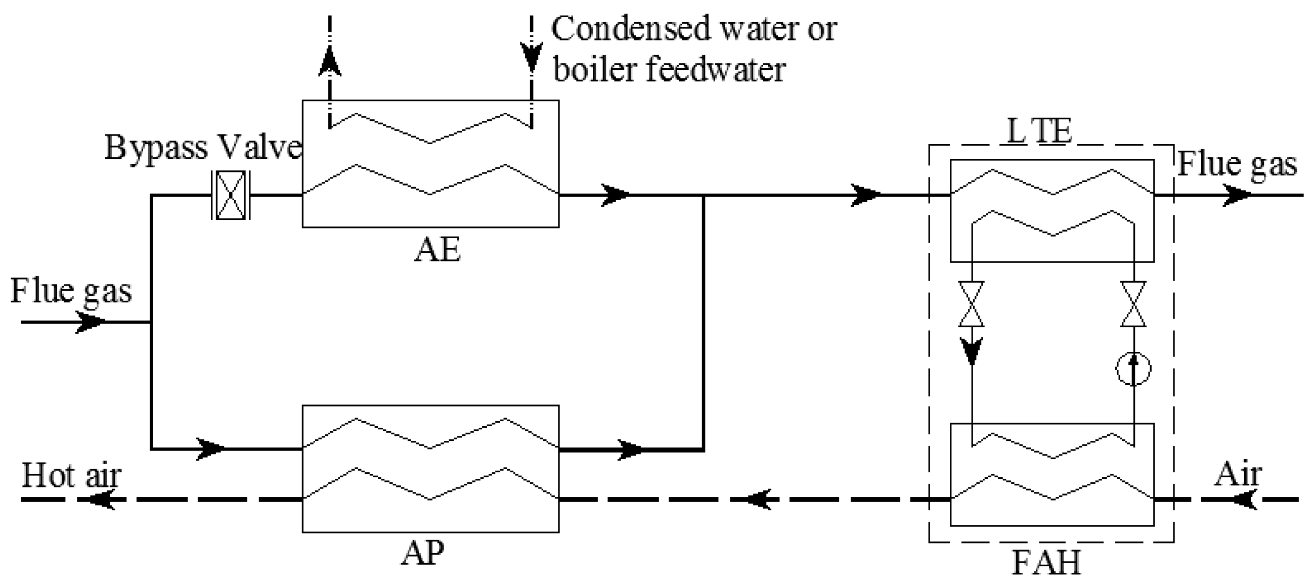
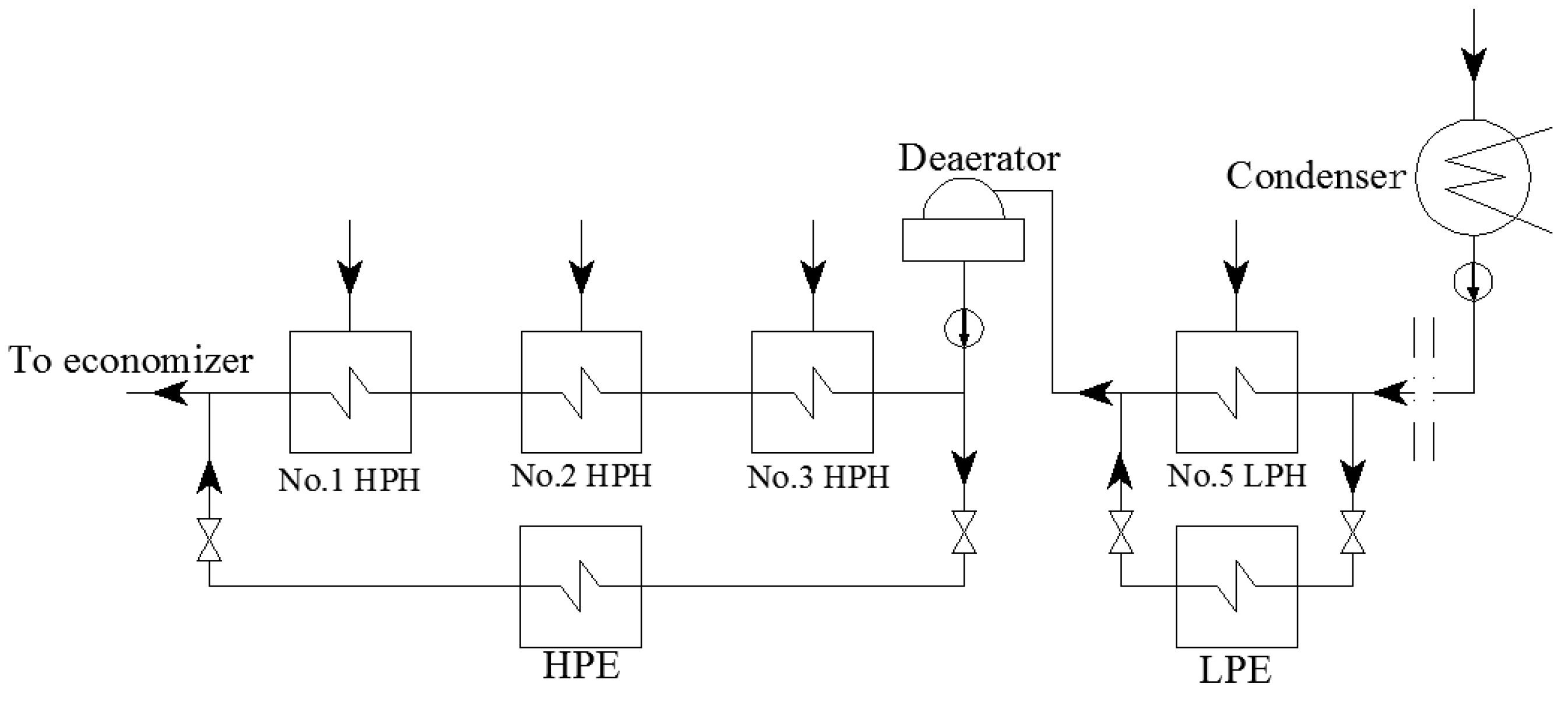
2.1. Description of CWHRS

Figure 1 shows the coupled high-low energy grade flue gas waste heat recovery system. The flue gas is divided into two parts before entering the air preheater (AP). One part enters the AP to heat the air; the other part enters into the additional economizer (AE) to heat the condensed water and/or the boiler high-pressure feed water. Then, the two parts merge into the LTE after the flue gas temperature drops to the original designed value at the exit of the AP. The LTE and the front-located air heater (FAH) are combined into a LTE-FAH system by a liquid medium closed loop, which transfers the flue gas heat to the air side to preheat the inlet air of the AP. The amount of flue gas entering the AE is generally not more than 30% of the total flue gas volume to ensure the outlet air temperature of the AP; it is adjusted using the bypass valve. Due to the high temperature of the flue gas at the inlet of the AP, the flue gas is high–grade energy. The temperature of the flue gas at the outlet of the AP is low, and the flue gas is low–grade energy. Thus, the system is called a coupled high-low energy grade flus gas waste heat recovery system.

2.2. Problem and Method

During CWHRS operation, the IFT varies with the change in load, coal characteristics, etc., and the IAT is different with the change in ambient temperature. This affects the waste heat recovery. There are two problems to be solved: how to optimize waste heat recovery when the IFT, the exhaust temperature, the inlet and outlet air temperature are determined by adjusting some parameter of the system; and how to optimize waste heat recovery when the IFT or the IAT changes and the exhaust temperature and out air temperature are constant. The problems were solved in the paper by theoretical analysis of CWHRS using the theory of heat balance, energy balance and exergy balance, and calculating the optimal parameters of a CWHRS installed on a 600 MW unit.

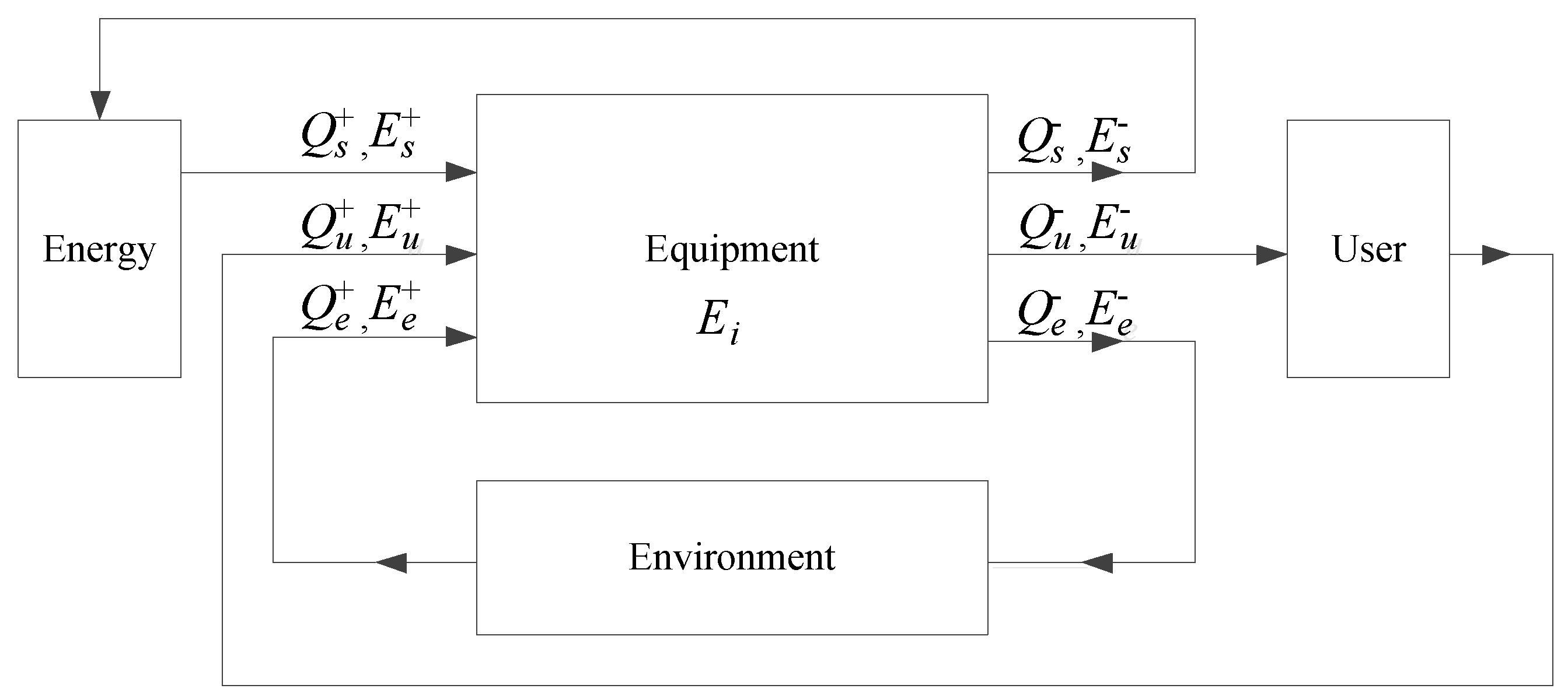
3. Energy Grade and Energy Grade Balance Theory

3.1. Energy Grade

In thermodynamics, the energy quality can be evaluated by the energy grade, which is equal to exergy divided by the total heat, and usually expressed as λ [22]. In the process of flue gas waste heat use, if the flue gas temperature is reduced from T1 to T2, the waste heat energy grade of the flue gas is calculated as follows [23]:
λ = e x q = c m ( T 1 T 2 T 0 ln T 1 T 2 ) c m ( T 1 T 2 ) = 1 T 0 T 1 T 2 ln T 1 T 2
where λ is the energy grade, ex is the released exergy of flue gas (kJ), q is the total heat (kJ), c is the average specific heat of flue gas in kJ/(kg·K), m is flue gas flow (kg), T0 is the ambient temperature (K), T1 is the initial temperature of the flue gas (K) and T2 is the final temperature of the flue gas (K).
According to Equation (1), as the initial temperature of the flue gas increases, the energy grade increases [22].

3.2. Energy Grade Balance Theory

Yang [24] stated that the imbalance in energy application is mainly due to the imbalance in the energy grade between the input side and output side of the energy user. The greater the energy grade difference, the more unreasonable the energy usage.
Figure 2 depicts the energy use model. In the figure, Q S + , Q u + and Q e + are the heat flow rates supplied to the equipment by the energy, user and environment, respectively; E S + , E u + and E e + are the exergy flow rates supplied to the equipment by the energy, user and environment, respectively; Q S , Q u and Q e are the heat flow rates exported to the energy, user and environment by the equipment, respectively; E S , E u and E e are the exergy flow rates exported to the energy, user and environment by the equipment, respectively; and Ei is the internal exergy loss of the equipment.
For the equipment, depending on the heat balance and exergy balance, there are the following equations:
Q s + + Q u + + Q e + = Q s + Q u + Q e
E s + + E u + + E e + = E s + E u + E e + E i
That is:
( Q s + Q s ) + Q e + = ( Q u Q u + ) + Q e
( E s + E s ) + E e + = ( E u E u + ) + E e + E i
The thermal efficiency and exergy efficiency of the equipment can be expressed, respectively, as follows, respectively:
η t , e = Q u Q u + Q s + Q s + Q e +
η e x , e = E u E u + E s + E s = 1 E e E e + + E i E s + E s
where, ηt,e is the thermal efficiency of the equipment and ηex,e is the exergy efficiency of the equipment.
The energy grade of the input energy supplied to the equipment can be calculated as:
λ i = E s + E s Q s + Q s + Q e +
The energy grade of the energy obtained by the equipment can be formulated as:
λ u = E u E u + Q u Q u + + Q e +
Energy grade balance expression can be calculated by dividing Equation (5) by Equation (4):
( E s + E s ) + E e + ( Q s + Q s ) + Q e + = ( E u E u + ) + E e + E i ( Q u Q u + ) + Q e
The energy supplied to the equipment by the environment is composed of anergy, so E e + = 0. Substituting Equations (6)–(9) into Equation (10), we obtain:
λ u = η e x , e η t , e λ i
The energy grade difference Δλ between the supplied energy and the obtained energy of the equipment is expressed as follows:
Δ λ = λ i λ u = ( 1 η e x , e η t , e ) λ i
The relative energy grade difference ξλ, that is, the EBC, can be calculated using Equation (13):
ξ λ = Δ λ λ i = 1 η e x , e η t , e
The energy grade difference or the EBC can be used as an indicator to evaluate the rationality of energy use. The larger is the absolute value of the energy grade difference or the EBC, the more unreasonable is the energy use. Conversely, the smaller is the absolute value of the energy grade difference or the EBC, the more reasonable the energy use.

4. Node Temperature of CWHRS

4.1. Heat Balance of Heat Exchangers in CWHRS

In CWHRS, LTE, FAH, AP and AE are all countercurrent heat exchangers, through which the air, water and liquid medium are heated by flue gas. Among the heat exchangers, there are the following heat balance equation, and heat transfer equations:
m h c h ( T i , h T o , h ) = m c c c ( T o , c T i , c )
m h c h ( T i , h T o , h ) = K A ( T i , h T o , c ) ( T o , h T i , c ) ln T i , h T o , c T o , h T i , c
where, mh and mc are mass flow rate of hot fluid and cold fluid, respectively (kg/s), ch and cc are average specific heat of hot fluid and cold fluid, respectively, in kJ/(kg·K), Ti,h and To,h are inlet temperature and outlet temperature of hot fluid, respectively (K), Ti,c and To,c are inlet temperature and outlet temperature of cold fluid, respectively (K), K is heat transfer coefficient of a heat exchanger in W/(kg·K) and A is heat transfer area in m2.
Equation (16) can be derived from Equations (14) and (15):
ln T i , h T o , c T o , h T i , c = K A m h c h ( 1 m h c h m c c c )
It can be inferred from Equation (16) that the heat balance of the heat exchanger can be maintained by reducing the mass flow rate of hot fluid when the inlet temperature of hot fluid rises, or increasing the mass flow rate of the cold fluid when the inlet temperature of cold fluid rises.
Regardless of the heat loss of the heat exchanger, the thermal efficiency of each heat exchanger is 1 in terms of heat balance. However, the exergy efficiency is less than 1 due to the exergy loss during the process of heat transfer. The exergy efficiency can be calculated by:
η e x = E c E h = m c c c ( T o , c T i , c T 0 ln T o , c T i , c ) m h c h ( T i , h T o , h T 0 ln T i , h T o , h )
where, ηex is the exergy efficiency of heat exchanger, Ec is the exergy receive by cold fluid (kJ) and Eh is the exergy released by hot fluid (kJ).

4.2. Node Temperature of the CWHRS

For CWHRS, the input heat includes the heat released from the AP, AE and LTE by the flue gas. The output heat includes the heat obtained by the air in the FAH and AP, and the heat obtained by the condensate or the boiler feed water in the AE. Without considering the heat loss of the pipeline and equipment and the temperature rise of the water or the air caused by the pump or the fan, the input heat can be expressed as follows:
Q i = Q l t e + Q f
where, Qi is the input heat of the CWHRS (kJ), Qlte is the heat released by the flue gas in the LTE (kJ), and Qf is the heat released by the flue gas in the AP and AE (kJ).
The output heat of the CWHRS can be calculated using Equation (19):
Q o = Q f a h + Q a p + Q a e
where, Qo is the output heat of the CWHRS (kJ), Qfah is the heat obtained by the FAH (kJ), Qap is the heat obtained by the AP (kJ) and Qae is the heat obtained by the AE (kJ).
According to heat balance theory, the input heat is equal to the output heat:
Q i = Q o
Q l t e + Q f = Q f a h + Q a p + Q a e
In the LTE-FAH system, the heat balance is:
Q l t e = Q f a h
Q l t e = c g , l t e ¯ m g ( T i l t e T o l t e )
Q f a h = c f a h ¯ m a ( T o f a h T i a )
where, c g , l t e ¯ is the average specific heat of the flue gas flowing through the LTE in kJ/(kg·K), mg is the flue gas flow (kg), T i l t e is the IFT of the LTE (K), T o l t e is the outlet flue gas temperature of the LTE (K), c f a h ¯ is the average specific heat of the air flowing through the FA in kJ/(kg·K), ma is the air flow (kg), T i a is he IAT of the FAH (K) and T o f a h is the outlet air temperature of the FAH (K).
In the CWHRS, the input exergy includes the exergy released from the AP, AE and LTE by the flue gas, as well as the input power by the fan and the pump for driving the flue gas, air and water during the operation of the system. The output exergy includes the exergy obtained by the air in the FAH and AP and the exergy obtained by the condensate or the boiler feed water in the AE. The input and output exergy can be respectively expressed as follows:
E i = E l t e + E f + W
E o = E f a h + E a p + E a e
where, Ei is the input exergy (kJ), Elte is the exergy released in the LTE (kJ), Ef is the exergy released in the AP and AE (kJ), W is the input power by the fan and the pump of the system in unit time (kJ), Eo is the output exergy of the CWHRS (kJ), Efah is the exergy obtained by the FAH (kJ), Eap is the exergy obtained by the AP (kJ) and Eae is the exergy obtained by the AE (kJ).
According to the Equation (1), the above exergy can be calculated by:
E l t e = c g , l t e ¯ m g [ T i l t e T o l t e T 0 ln T i l t e T o l t e ]
E f = c f ¯ m g [ T i f T i l t e T 0 ln T i f T i l t e ]
E f a h = c f a h ¯ m a [ T o f a h T i a T 0 ln T o f a h T i a ]
E a p = c a p ¯ m a [ T o a T o f a h T 0 ln T o a T o f a h ]
E a e = c w m w [ T o a e T i a e T 0 ln T o a e T i a e ]
where, c f ¯ the average specific heat of flue gas flowing through the AP in kJ/(kg·K), T i f is the IFT of the AP (K), c a p ¯ is the average specific heat of air flowing through the AP in kJ/(kg·K), T o a is the outlet air temperature of the AP (K), cw is the specific heat of water in kJ/(kg·K), mw is the water flow in the AE (kg), T i a e is the inlet water temperature of the AE (K) and T o a e is the outlet water temperature of the AE (K).
Without considering the heat loss of a CWHRS, the thermal efficiency of the system is 1. The exergy efficiency of the system can be expressed as follows:
η e x , s = E f a h + E a p + E a e E l t e + E f + W
Based on the energy grade balance theory, the energy grade of the input energy of the CWHRS can be formulated as:
λ i = E i Q i = E l t e + E f + W Q l t e + Q f
The energy grade of the energy obtained by the CWHRS can be expressed as:
λ o = E o Q o = E f a h + E a p + E a e Q f a h + Q a p + Q a e
The relative energy grade difference of the CWHRS can be calculated as:
ξ s = λ i λ o λ i = 1 λ o λ i
Considering Equations (21) and (27)–(35), ξλ can be calculated as:
ξ s = 1 { c f a h ¯ m a [ T o f a h T i a T 0 ln T o f a h T i a ] + c a p ¯ m a [ T o a T o f a h T 0 ln T o a T o f a h ] + c w m w [ T o a e T i a e T 0 ln T o a e T i a e ] } c g , l t e ¯ m g [ T i l t e T o l t e T 0 ln T i l t e T o l t e ] + c f ¯ m g [ T i f T i l t e T 0 ln T i f T i l t e ] + W
Given the design condition of the CWHRS, T o l t e , T i f , T i a , T o a and mg, ma, mw are all deterministic values. T o f a h can be derived by the Equations (22)–(24). The IFT of the LTE T i l t e is defined as the node temperature of the CWHRS. When the absolute value of ξλ is the smallest, the IFT of the LTE is the ONT of the system. Equation (36) is complicated and the ONT can be determined using the mapping method or trial calculation.
For CWHRS of a certain design scale, it can be inferred that the outlet flue gas temperature of the LTE will be high when the node temperature is high, which is not conducive to reduce flue gas temperature. Conversely, the heat transferred from the LTE to the FAH decreases and the air temperature may not rise to the required value when the node temperature is low. Therefore, controlling the reasonable node temperature is the key to improving the heat use efficiency of the CWHRS.

5. Node Temperature Calculation Case and Analysis

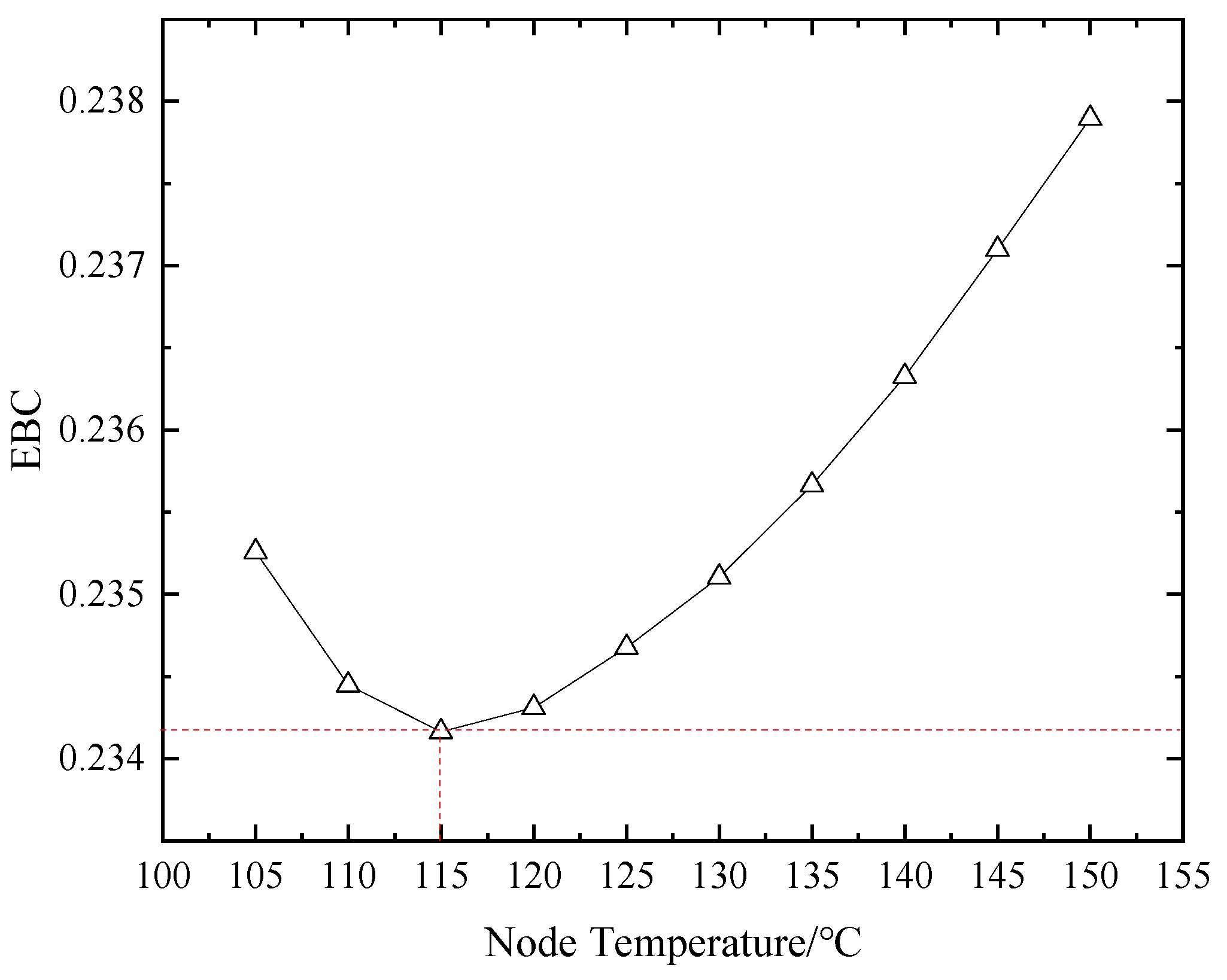
5.1. Node Temperature Calculation

Taking a N600-24.2/566/566 supercritical 600 MW unit as an example, the influence of node temperature on the EBC was analyzed. In the CWHRS of the unit, the AE consists of a high-pressure economizer (HPE) and a low-pressure economizer (LPE), as shown in Figure 3. The inlet water of the LPE is taken from the inlet of the No.5 low-pressure heater (LPH), and the return water flows into the outlet of the No.5 LPH. The inlet water of the HPE is obtained from the outlet of the feed water pump and the return water flows into the outlet of the No.1 high-pressure heater.
Table 1 shows the fuel characteristics of the N600-24.2/566/566 unit, and the calculation parameters of the CWHRS are shown in Table 2.
Using the data in Table 1 and Table 2, the inlet and outlet flue gas temperature, the inlet and outlet air temperature of CWHRS and the logarithmic temperature differences of HPE, LPE and LTE were kept constant, and the system maintained heat balance by adjusting the bypass flue gas flow and the water flow through the HPE, LPE and LTE. The exergy efficiency of the heat exchangers and the system were calculated. Figure 4 shows the change trend of the exergy efficiency of heat exchangers and the CWHRS at different node temperatures. With the rising of node temperature, the exergy efficiency of CWHRS changed slightly: firstly increasing, then decreasing, reaching its maximum value when the node temperature was about 115 °C. This means the system recovers the most waste heat at the node temperature. The changing trend of the system’s exergy efficiency is similar to coal consumption rate reduction curve of a LTE installing on a 1000 MW unit in reference [18]. The exergy efficient of HPE remains constant because the inlet and outlet parameters of the exchangers remain unchanged. The exergy efficient LPE increased due to the increased water flow through LPE. The exergy efficiency of LTE increased, which indicated that the rising node temperature was good for improving the waste heat recovery effect of LTE. The exergy efficiency of FAH increased rapidly, which illustrates that the exergy gained by air increased quickly with increasing node temperature. The exergy efficiency of AP increased slowly; the elevated node temperature had less impact on AP.
The EBCs of the CWHRS at different node temperatures are calculated using Equation (36). Figure 5 illustrates the change trend of the EBCs under different node temperatures. The temperature corresponding to the intersection of the dotted line and the solid line in the Figure is the ONT of the CWHRS, which is about 115 °C, that is, the EBC is the smallest and the waste heat use effect of CWHRS is the most reasonable when the node temperature is about 115 °C. With increasing node temperature from 100 to 155 °C, the EBC is greater than zero and the EBC changes slightly, decreasing firstly when the node temperature is less than 115 °C, then rising when the node temperature is more than 115 °C. This indicates that, with changing node temperature, the EBC has the lowest value and the CWHRS cannot achieve energy grade balance; however, the EBC has an optimal value according to energy balance theory. To ensure the rationality of the waste heat use in the CWHRS, the node temperature should be increased when it is less than ONT, and decreased when it is more than ONT with other parameters unchanged. The ONT is recommended as the designed node temperature to ensure waste heat use recovery when designing the system.

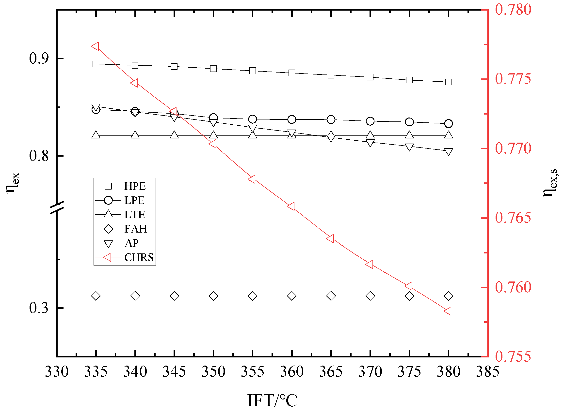
5.2. Influence of IFT and IAT on Exergy Efficiency and EBC

During the operation of the unit, due to changes in the fuel, unit load and environment temperature, the IFT and the IAT will change. The node temperature and the EBC of the CWHRS will deviate from the design conditions according to the theory of heat balance. In order to ensure the efficient operation of the CWHRS, it is necessary to analyze the change trends of the EBC when IFT or IAT change, which can provide theoretical support for the operation adjustment of the system.

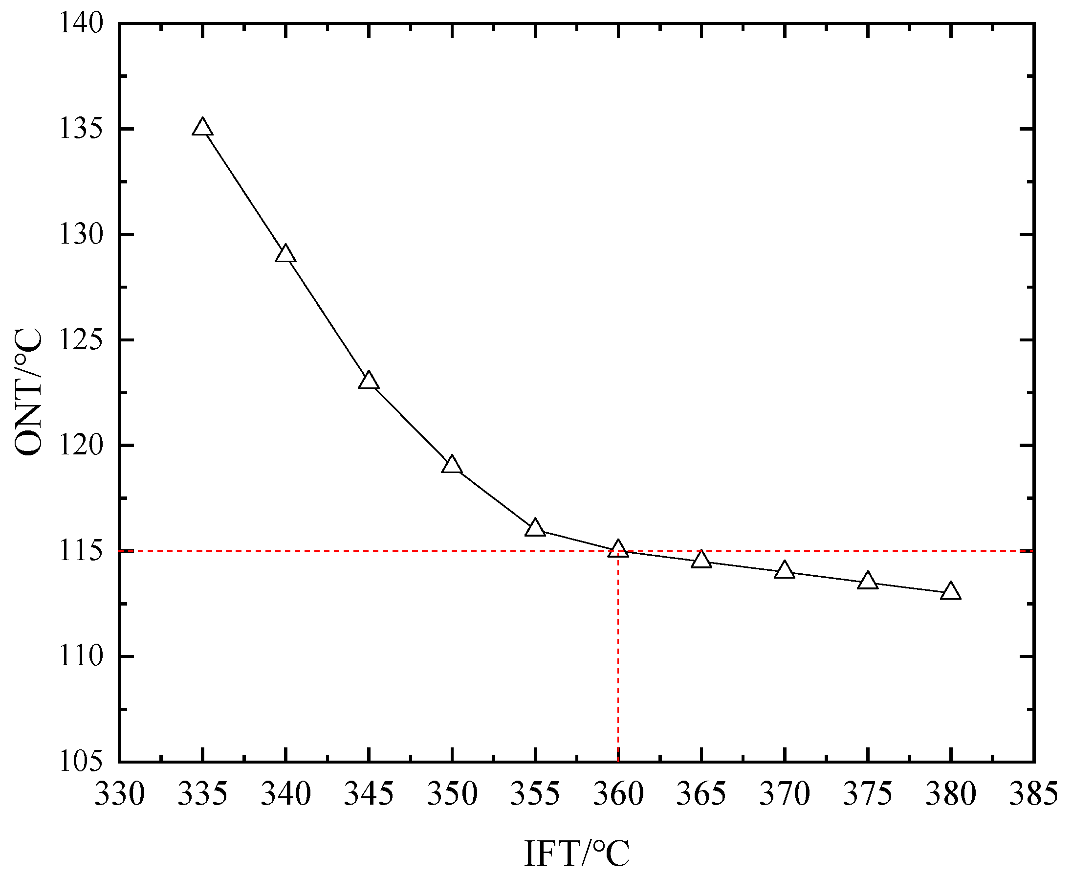
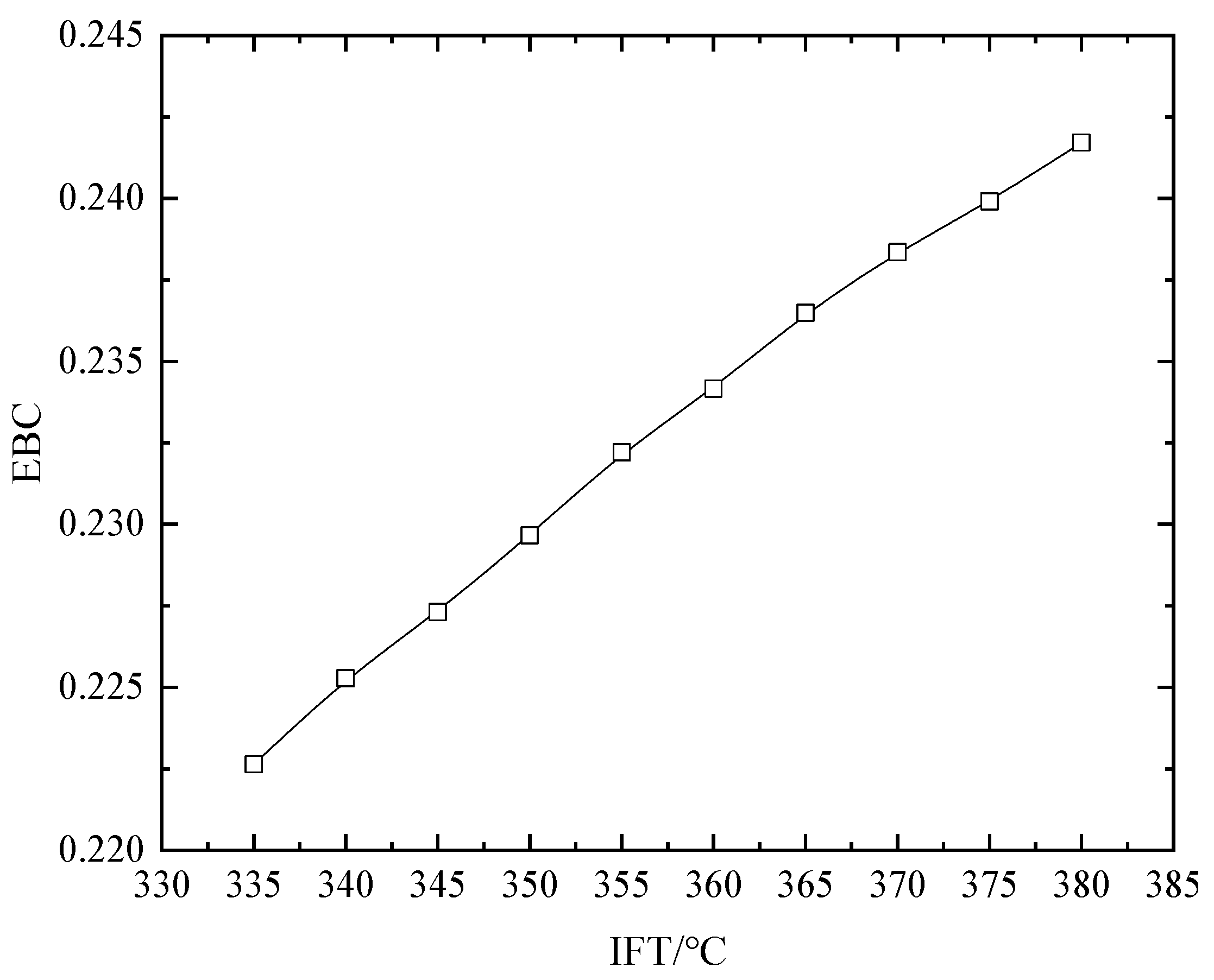
5.2.1. Influence of IFT on Exergy Efficiency and EBC

Taking the above-mentioned CWHRS of the 600 MW unit as an example, when the IAT is 20 °C, the node temperature is 115 °C, the exhaust gas temperature is 85 °C and the out let air temperature of AP is 315 °C, changing the IFT, the exergy efficient of the heat exchangers and the system were calculated and are displayed in Figure 6. With increasing IFT, the exergy efficiency of the system declined rapidly. This shows that keeping the node temperature at 115 °C is unfavorable for waste heat recovery when IFT rises. The exergy efficiency of LTE and FAH were kept unchanged, because the inlet and outlet temperature of the heat exchangers were constant when calculating. The exergy efficiency of HPE, LPE, and AP decreased. This means that an increased IFT worsens the waste heat recovery effect when the node temperature is kept 115 °C, resulting in the decreased exergy efficiency of the system.
The EBC of the system under different IFT was calculated and the result is shown in Figure 7. As the IFT rose, the EBC increased. The rising EBC shows that the energy grade imbalance degree of the system will increase, and the waste heat use of the system was more unreasonable with increasing IFA when the node temperature was kept constant. Moreover, the decreasing exergy efficiency of CWHRS verifies the result. It is necessary to stop the increase in EBC to ensure the effect of waste heat recovery.
In the operation of the units, the IFT is determined by factors such as unit load and fuel characteristics, and it cannot be adjusted freely. The optimal EBC of CWHRS can be obtained by changing the node temperature by adjusting the bypass flue gas flow or water flow of AE. According to the change trend in EBC with node temperature changing shown Figure 5, the node temperature should be increased when the IFT is less than 360 °C and should be decreased when the IFT is more than 360 °C. Through calculating, the ONT under different IFT is shown in Figure 8. As the IFT rises from 335 to 380 °C, the ONT should be decreased from about 135 °C to about 113 °C to ensure the EBC is the lowest. With rising IFT, the ONT reduction is smaller. Therefore, the node temperature can be adjusted as a variable to ensure the effect of waste heat use in the operation of a CWHRS. As the IFT is higher or lower than the design temperature, the node temperature should be adjusted to be lower or higher than the designed ONT, respectively.

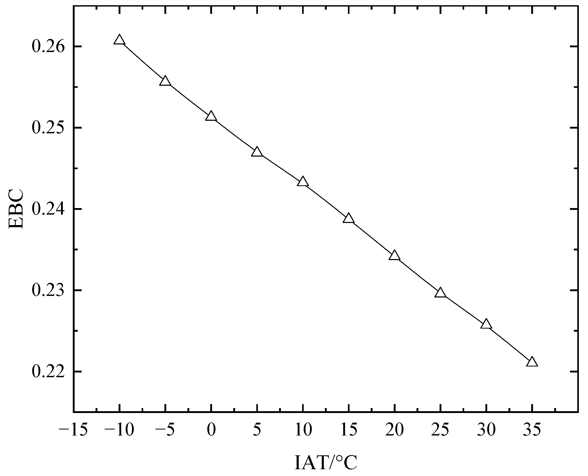
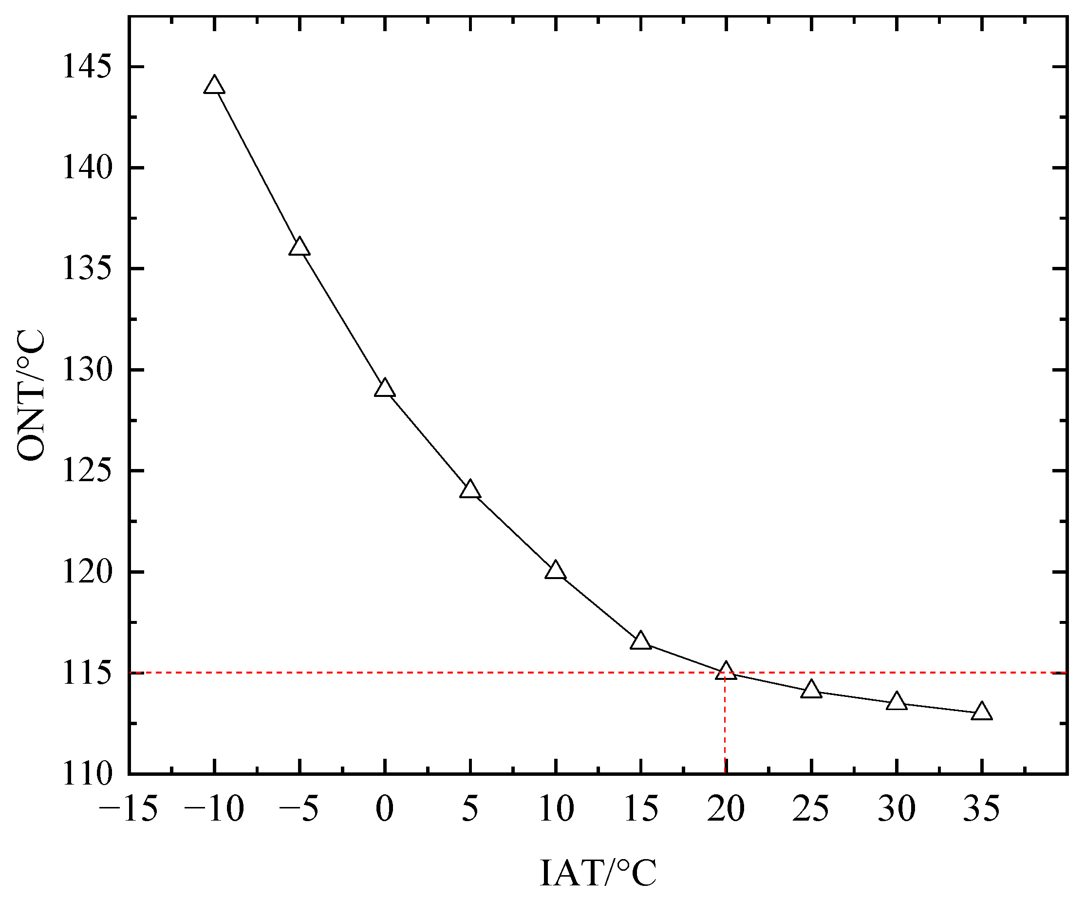
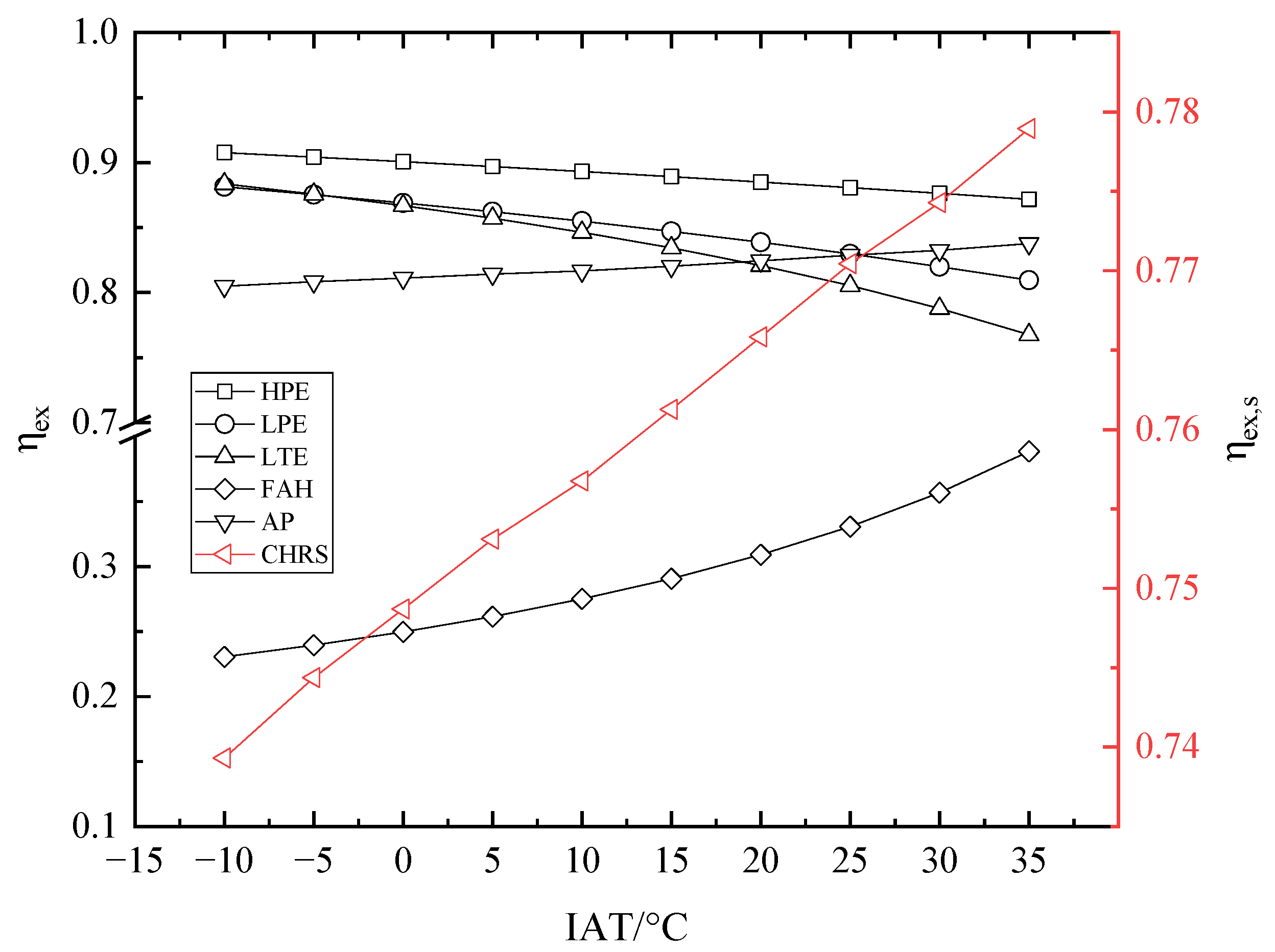
5.2.2. Influence of IAT on Exergy Efficiency and EBC

In the operation of CWHRS, when the ambient temperature changes, the IAT inevitably changes: this causes the system to deviate from the designed condition. When the IFT is 360 °C, the node temperature is 115 °C, the exhaust gas temperature is 85 °C, and the out let air temperature of AP is 315 °C, changing the IAT, the exergy efficiency of the heat exchangers, and the system under different IAT were calculated and the results are shown in Figure 9. With rising IAT, the exergy efficiency of the system changed slightly and increased. This means increasing IAT improves the waste heat recovery of the system if the node temperature is kept constant. The exergy efficiency of HPE and LPE decreased mainly because of ambient temperature change according to Equation (17). The exergy efficiency of LPE decreased due to the reducing exergy gained by water side inducing by increasing of IAT. The exergy efficiency of FAH increased because of the decreased exergy loss causing by the decreasing heat transfer temperature difference of the exchangers. The exergy efficiency of AP increased slightly and was less affected by increasing IAT.
The EBC of the mentioned CWHRS of the 600 MW unit was calculated under different IAT, and the result is demonstrated in Figure 10. With an increasing IAT, the EBC decreased. The rising IAT improved the energy grade balance of the system and enhanced waste heat recovery under the given conditions. The decreasing exergy efficiency of the system confirmed the result. Increasing IAT is beneficial for waste heat recovery in a CWHRS.
As the ambient temperature changed, the IAT varied correspondingly; the system may deviate from the optimal condition. To optimize waste heat recovery, the node temperature can also be used as an adjustment parameter, with other parameters unchanged, by changing the flue gas flow or water flow through the AE based on Equation (17). The calculated ONT at different IAT is displayed in Figure 11. When the IAT increased from −10 to 35 °C, the ONT varied from about 144 °C to 113 °C, respectively. Accordingly, the node temperature should be adjusted based on the designed ONT. When the IAT was higher or lower than the design value, the node temperature should be less or more than the design ONT to maintain optimal EBC, respectively. In practical engineering, a higher ONT is beneficial for increasing the IAT of AP and preventing low temperature corrosion of AP and LTE when the IAT is low.

6. Conclusions

Based on the theory of heat balance, exergy balance and energy grade balance, a CWHRS was analyzed, and the IFT of LTE was defined as the node temperature of the system. Taking a CWHRS installed on a 600 MW unit as an example, the exergy efficiency of heat exchangers and the system were analyzed and the EBC of the system under different node temperatures, IFTs and IATs were calculated. Our conclusions are as follows.
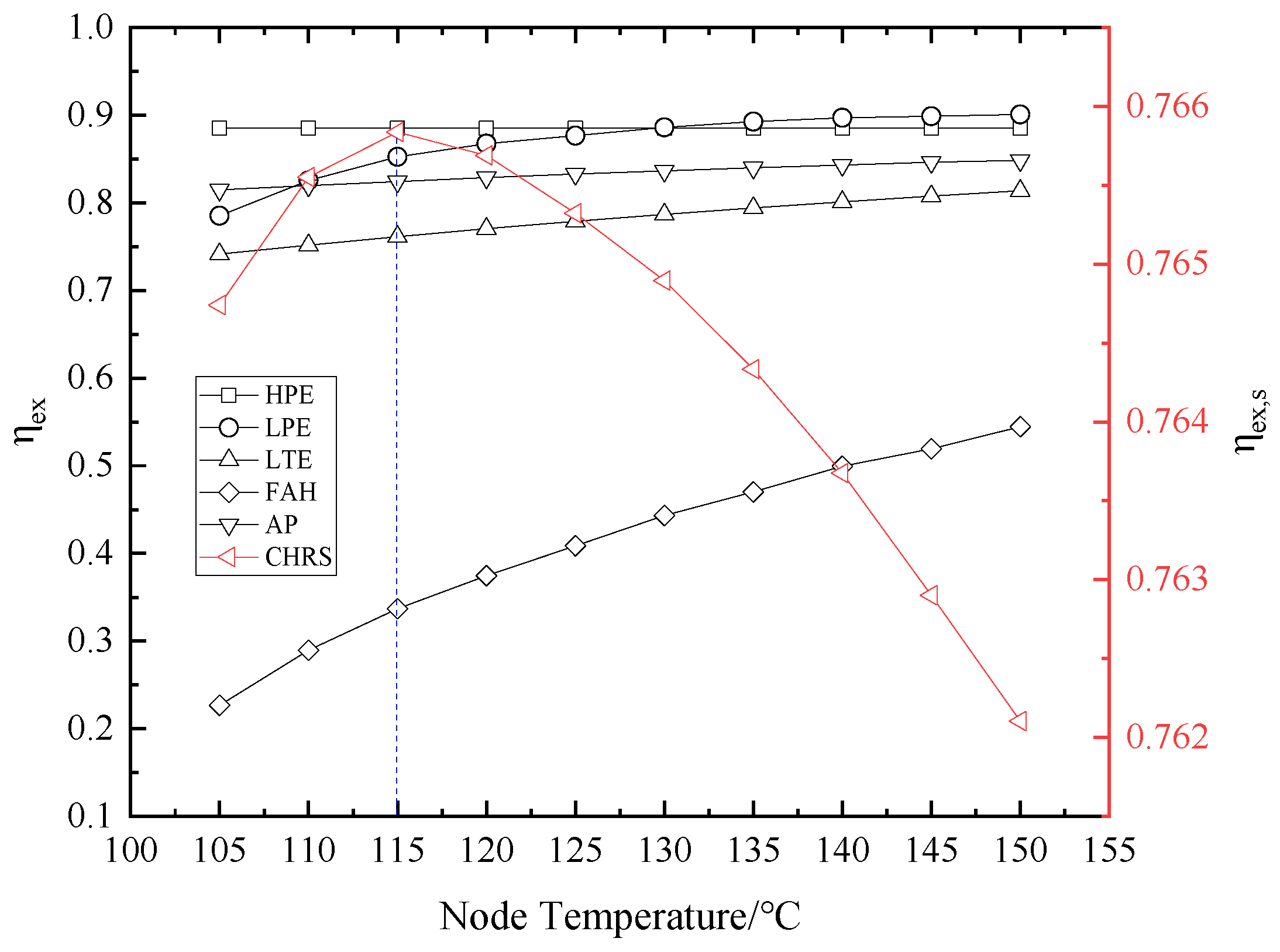
  • When the absolute value of EBC is the lowest, the node temperature of CWHRS is the ONT, and the system achieves optimal waste heat recovery. The ONT of the CWHRS of the 600 MW unit is about 115 °C under given conditions.
  • With increasing node temperature of the CWHRS, the EBC first decreases, then increases. At about 115 °C, the smallest EBC was calculated and the system has the maximum exergy efficiency. The node temperature should be increased when the IFT is less than 360 °C and decreased when the IFT is more than 360 °C to achieve the ONT.
  • With increasing IFT, the exergy efficiency of the CWHRS decreases and the EBC increases, and the node temperature should be decreased to obtain the ONT. The ONT should be decreased from about 135 °C to about 113 °C when the IFT increases from 335 °C to 380 °C, respectively.
  • With increasing IAT, the exergy efficiency of CWHRS increases and the EBC decreases, and the node temperature should be decreased to obtain the ONT. The ONT should be decreased from about 144 °C to about 113 °C when the IAT increases from −10 °C to 35 °C, respectively.
  • The node temperature is recommend as an adjustment parameter in a CWHRS to optimize waste heat recovery, and the ONT can be obtained by adjusting the bypass flue gas flow and water flow of AE.
  • When IFT or IAT changes, according to the change trends of the ONT, adjusting the node temperature to a reasonable value is beneficial to ensure the rationality of waste heat use and efficient operation of CWHRS.
In this study, since the heat losses of the heat exchanger and the pipeline were not considered, the thermal efficiency of the system was neglected. In future work, research will be conducted through experiments.

Author Contributions

All authors conceived the study, J.L. wrote the manuscript and F.S. reviewed the manuscript and provided valuable suggestions.

Funding

This work was supported by the National Development and Reform Commission Fund of the Power Industry Low-carbon Technology Innovation and Industrialization Demonstration Projects [Development and Reform Office High-tech (2013) 1819].

Conflicts of Interest

The authors declare no conflict of interest.

References

  1. Li, Y.; Chang, S.; Fu, L.; Zhang, S. A technology review on recovering waste heat from the condensers of large turbine units in China. Renew. Sustain. Energy Rev. 2016, 58, 287–296. [Google Scholar] [CrossRef]
  2. Ye, T. Thermal Power Plant, 4th ed.; China Electric Power Press: Beijing, China, 2012; pp. 7–8. ISBN 9787512329317. (In Chinese) [Google Scholar]
  3. Fu, Y.; Sun, J.; Cai, W.; Jiang, H.; Jia, M.; Miao, Y.; Zhang, Y.; Wang, G. Analysis on technology of waste heat recovery from exhaust gas of power boiler using low-pressure economizer. Huadian Technol. 2013, 35, 64–66. (In Chinese) [Google Scholar]
  4. Jouhara, H.; Khordehgah, N.; Almahmoud, S.; Delpech, B.; Chauhan, A.; Tassou, S.A. Waste heat recovery technologies and applications. Therm. Sci. Eng. Prog. 2018, 6, 268–289. [Google Scholar] [CrossRef]
  5. Wang, C.; He, B.; Sun, S.; Wu, Y.; Yan, N.; Yan, L.; Pei, X. Application of a low pressure economizer for waste heat recovery from the exhaust flue gas in a 600 MW power plant. Energy 2012, 48, 196–202. [Google Scholar] [CrossRef]
  6. Wang, C.; He, B.; Yan, L.; Pei, X.; Chen, S. Thermodynamic analysis of a low-pressure economizer based waste heat recovery system for a coal-fired power plant. Energy 2014, 65, 80–90. [Google Scholar] [CrossRef]
  7. Huang, X.; Shi, Y.; Sun, F.; Lu, W.; Qi, L. Practice of low pressure economizer installed in 670 t/h coal-fired boiler to reduce the exhaust gas temperature. Electr. Power 2008, 41, 55–58. (In Chinese) [Google Scholar]
  8. Stevanovic, V.D.; Wala, T.; Muszynski, S.; Muszynski, S.; Milic, M.; Jovanovic, M. Efficiency and power upgrade by an additional high pressure economizer installation at an aged 620MWe lignite-fired power plant. Energy 2014, 66, 907–918. [Google Scholar] [CrossRef]
  9. Xu, G.; Xu, C.; Yang, Y.; Fang, Y.; Li, Y.; Song, X. A novel flue gas waste heat recovery system for coal-fired ultra-supercritical power plants. Appl. Therm. Eng. 2014, 67, 240–249. [Google Scholar] [CrossRef]
  10. Huang, S.; Li, C.; Tan, T.; Fu, P.; Xu, G.; Yang, Y. An Improved System for Utilizing Low-Temperature Waste Heat of Flue Gas from Coal-Fired Power Plants. Entropy 2017, 19, 423. [Google Scholar] [CrossRef]
  11. Liu, J.; Sun, F.; Ma, L.; Wei, W. Coupled high-low energy level flue gas heat recovery system and its application in 1000 MW ultra-supercritical double reheat coal-fired unit. In Proceedings of the ASME 2017 Power Conference Joint with ICOPE-17, Charlotte, NC, USA, 26–30 June 2017. [Google Scholar]
  12. Han, Y.; Xu, G.; Zheng, Q.; Xu, C.; Hu, Y.; Yang, Y.; Lei, J. New heat integration system with bypass flue based on the rational utilization of low-grade extraction steam in a coal-fired power plant. Appl. Therm. Eng. 2017, 113, 460–471. [Google Scholar] [CrossRef]
  13. Xu, G.; Huang, S.; Yang, Y.; Wu, Y.; Zhang, K.; Xu, C. Techno-economic analysis and optimization of the heat recovery of utility boiler flue gas. Appl. Energy 2013, 112, 907–917. [Google Scholar] [CrossRef]
  14. Espatolero, S.; Cortés, C.; Romeo, L.M. Optimization of boiler cold-end and integration with the steam cycle in supercritical units. Appl. Energy 2010, 87, 1651–1660. [Google Scholar] [CrossRef]
  15. Espatolero, S.; Romeo, L.M.; Cortés, C. Efficiency improvement strategies for the feedwater heaters network designing in supercritical coal-fired power plants. Appl. Therm. Eng. 2014, 73, 449–460. [Google Scholar] [CrossRef]
  16. Guo, J.; Xu, T.; Cheng, L. Thermodynamic analysis of waste heat power generation system. Energy 2010, 35, 2824–2835. [Google Scholar] [CrossRef]
  17. Butcher, C.J.; Reddy, B.V. Second law analysis of a waste heat recovery based power generation system. Int. J. Heat Mass Transf. 2007, 50, 2355–2363. [Google Scholar] [CrossRef]
  18. Song, J.; Li, Y.; Xu, Q.; Han, Y.; Xu, G. Analysis and optimization of the low temperature economizer under off-design operating conditions. Power Syst. Eng. 2015, 31, 17–20. (In Chinese) [Google Scholar]
  19. Song, J.; Li, Y.; Li, F.; Han, Y.; Xu, G. Energy-saving effect variable condition analysis of depth waste heat utilization system under off-design condition in Utility Boiler. Boiler Technol. 2015, 46, 6–12. (In Chinese) [Google Scholar]
  20. Huang, X.; Ping, Y.; Sun, F. Optimum water flow distribution for a low economizer system in power stations. J. Hydrodyn. 2003, 18, 526–530. (In Chinese) [Google Scholar]
  21. Wei, W.; Sun, F.; Shi, Y.; Ma, L. Theoretical prediction of acid dew point and safe operating temperature of heat exchangers for coal–fired power plants. Appl. Therm. Eng. 2017, 123, 782–790. [Google Scholar] [CrossRef]
  22. Wu, Y.; Yang, W.; Yang, D. Rational use of waste heat resources. Colored Smeltin. 1982, 8, 12–18. (In Chinese) [Google Scholar]
  23. Yu, L.; Zhu, Y.; Wu, Y. Medium and Low Temperature Waste Heat Power Generation Technology; Shanghai Jiaotong University Press: Shanghai, China, 2015; pp. 1–3. ISBN 9787313140913. (In Chinese) [Google Scholar]
  24. Yang, D. Exergy Analysis and Energy Grade Analysis; Science Press: Beijing, China, 1986; pp. 130–141. ISBN 15031687. (In Chinese) [Google Scholar]
Figure 1. Coupled high-low energy grade flus gas waste heat recovery system. AE: Additional Economizer; AP: Air Preheater; LTE: Low Temperature Economizer; FAH: Front located Air Heater.
Energies 12 00248 g001
Figure 2. Energy use model [24]. Q S + , Q u + , Q e + : Heat flow rates supplied to the equipment by the energy, user and environment, respectively. Q S , Q u , Q e : Heat flow rates exported to the energy, user and environment by the equipment, respectively. E S + , E u + , E e + : Exergy flow rates supplied to the equipment by the energy, user and environment, respectively. E S , E u , E e : Exergy flow rates exported to the energy, user and environment by the equipment, respectively. Ei: Internal exergy loss of the equipment.
Energies 12 00248 g002
Figure 3. AE position in the regenerative system of a 600 MW unit. HPE: High–Pressure Economizer; LPE: Low–Pressure Economizer; HPH: High–Pressure Heater; LPH: Low–Pressure Heater.
Energies 12 00248 g003
Figure 4. Exergy efficiency of heat exchangers and CWHRS at different node temperatures.
Energies 12 00248 g004
Figure 5. Relationship between the node temperature and the energy-grade balance coefficient (EBC).
Energies 12 00248 g005
Figure 6. Exergy efficiency of heat exchangers and CWHRS under different IFT.
Energies 12 00248 g006
Figure 7. Influence of IFT on EBC.
Energies 12 00248 g007
Figure 8. Optimal node temperature (ONT) at different IFT.
Energies 12 00248 g008
Figure 9. Exergy efficiency of heat exchangers and CWHRS under different IAT.
Energies 12 00248 g009
Figure 10. Influence of IAT on EBC.
Energies 12 00248 g010
Figure 11. ONT at different IAT.
Energies 12 00248 g011
Table 1. Fuel characteristics of the N600-24.2/566/566 unit.
No.ItemSymbolUnitValue
1MoistureMt%14.00
2AshAar%11.00
3CCar%60.31
4HHar%3.62
5NNar%0.70
6OOar%9.94
7SSt,ar%0.43
8Low Heating ValueQnet,v,arMJ/kg23.765
Table 2. Calculation parameters of the coupled high-low energy grade flus gas waste heat recovery systems (CWHRS).
No.ItemUnitValue
1Inlet flus gas temperature of the AP°C360
2Outlet flue gas temperature of LTE°C85
3Inlet air temperature of the FAH°C20
4Outlet air temperature of the AP°C315
5Inlet water temperature of LPE°C96
6Outlet water temperature of LPE°C165
7Inlet water temperature of HPE°C180
8Outlet water temperature of HPE°C275
9Water flow of LPEt/h93
10Water flow of HPEt/h147
11Input power of fans and pumpsMJ/h10.32

