Igniting Soaring Droplets of Promising Fuel Slurries

 ,
,
Abstract
:1. Introduction
1.1. Reasons for the Increased Interest in Water-Containing Slurry Fuels
- (i)
- cost-effectiveness of CLF; compared to fuel oil and coal, the cost of 1 ton of CLF is 1.5–2.5 times lower; operating costs for storage, transportation and combustion are 20–30% lower;
- (ii)
- due to almost complete burnout of coal particles in CLF, gaseous anthropogenic emissions into the atmosphere are minimal and comparable to emissions from gas combustion;
- (iii)
- in terms of technological effectiveness, CLF is fire- and explosion-proof; it can be stored at a wide temperature range; slagging is reduced; there is no dependence on the properties and origin of the CLF components;
- (iv)
- CLF can be used as primary and additional fuel in all operating conditions regardless of the region; virtually any coal can be used to prepare CLF;
- (v)
- among the main combustible components of CLF, in addition to fine coal, there may be numerous wastes of coal enrichment and oil refinement; in this case, it is possible to dispose of large amounts of these wastes, to release the occupied territory, and to reduce the consumption of fossil fuels for producing thermal and electric energy.
- (i)
- moisture, which can make up to 40% of CLF, is a ballast, and part of the energy from fuel combustion is spent on the phase transition of water from liquid to gaseous state;
- (ii)
- typical CLF obtained on most units (at various technologies) retains stability (does not stratify) only for 30–70 h. Modern equipment allows increasing this parameter up to 10–15 days, and even up to a year without the use of additives-stabilizers. Limited stability forces the use of additives-plasticizer or special processing methods when it is necessary to increase the CLF shelf life, which obviously increases the fuel cost. The way out of this situation is to prepare CLF immediately before combustion. This approach provides a CLF daily supply reserve in the immediate vicinity of the consumer. The main fuel supply in this case is provided by the initial coal reserves;
- (iii)
- high abrasive wear of the injectors took place at the first stages of CLF application. For example, in Russia, China, India, Japan and Poland the first nozzles served no more than 30–40 h. In modern conditions, these issues have been resolved up to the manufacturing of serial burners for CLF.
1.2. Modern Technology of Composite Liquid Fuel (CLF) Combustion
1.3. Limitations of Modern Methods of Investigation of CLF Ignition and Combustion
2. Experimental Setup and Methods
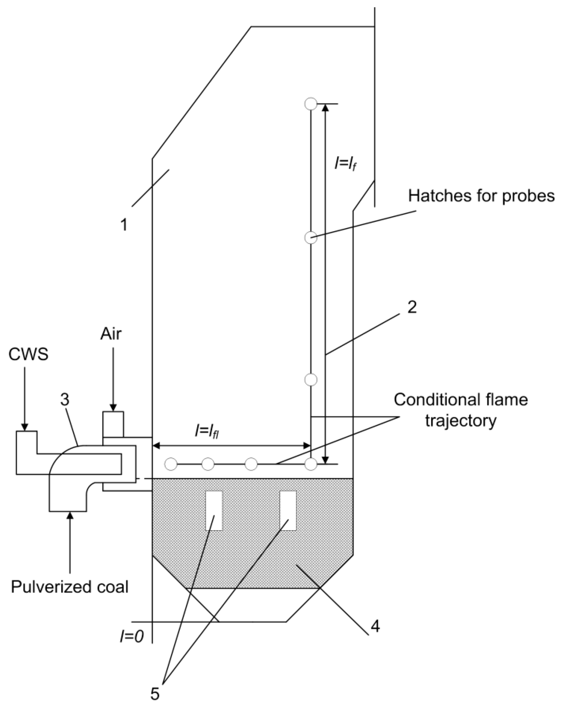
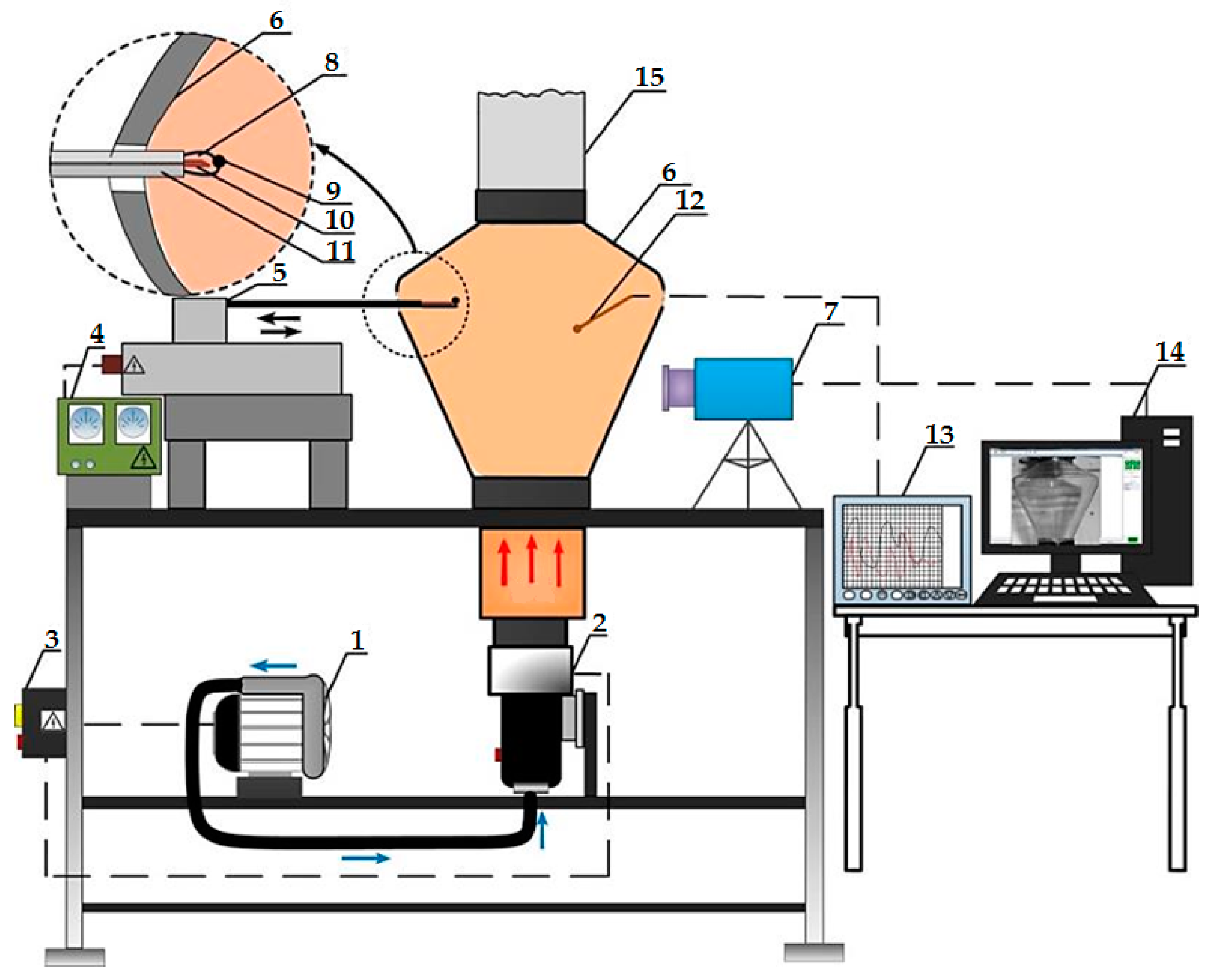
2.1. Typical Industrial Layouts of Units for CLF Combustion
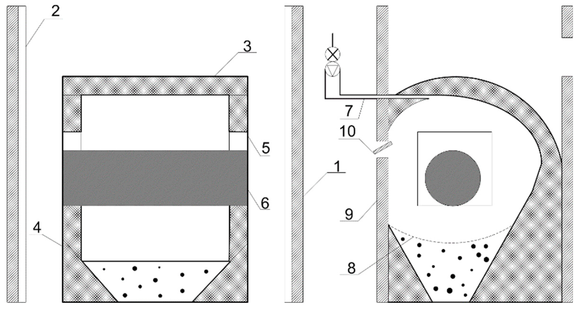
2.2. Typical Diagrams of Experimental Setups for Studying CLF Combustion
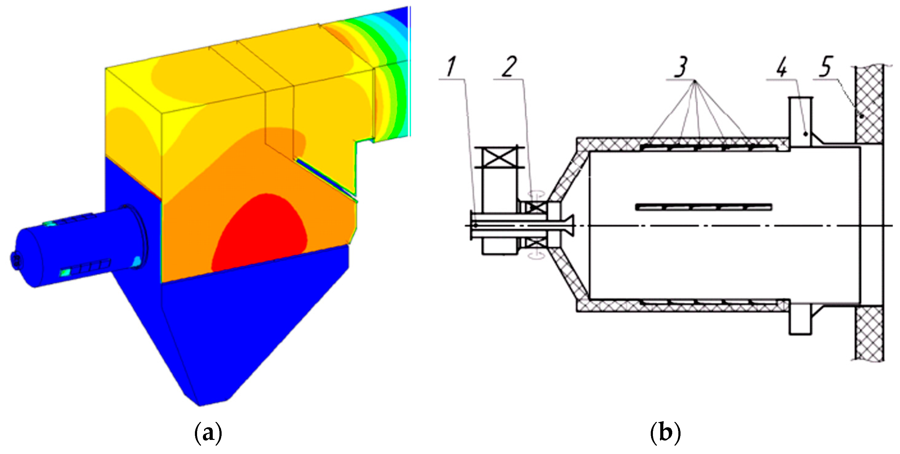
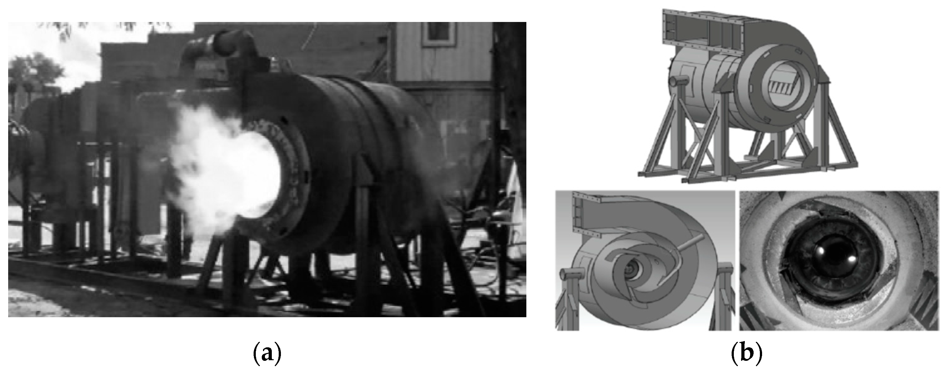
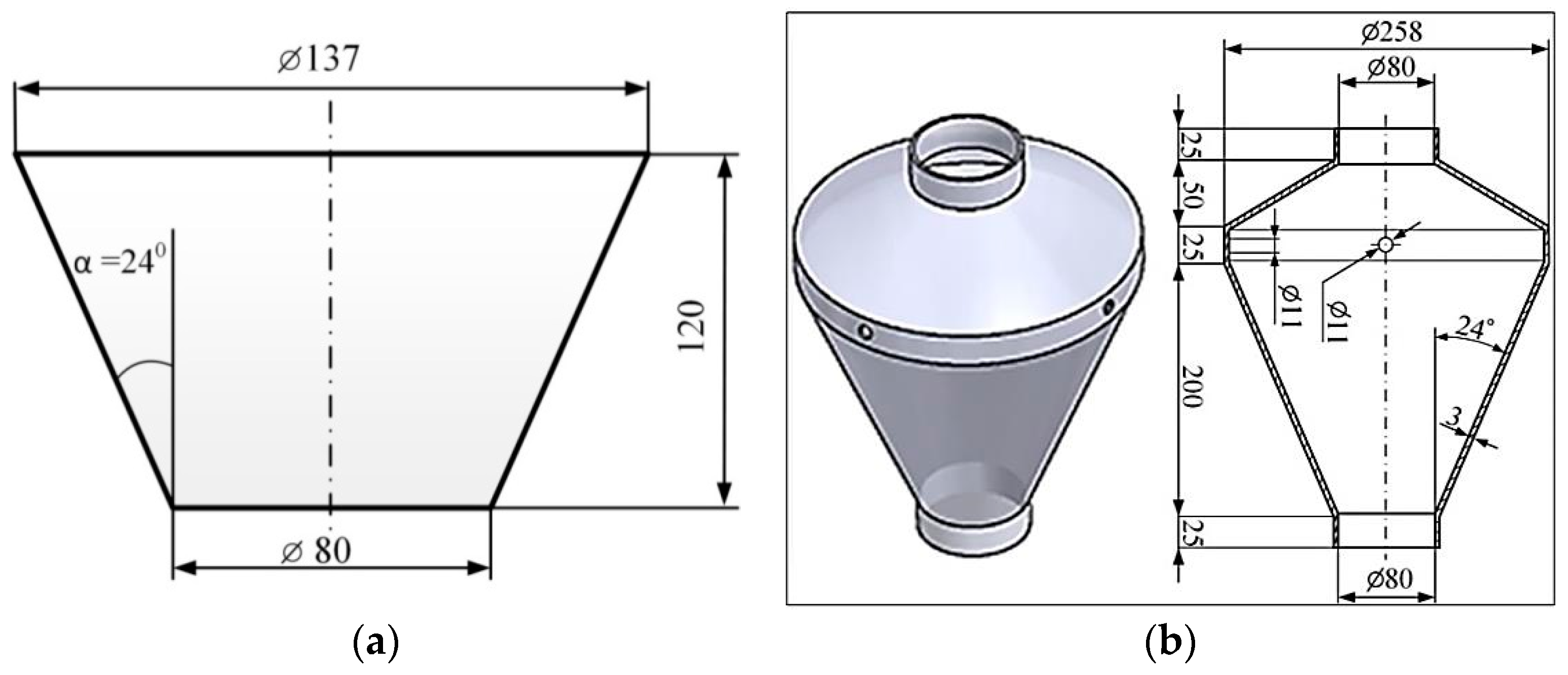
2.3. Designing the Model Combustion Chamber
- 1
- The coefficient of droplet sphericity (spherical shape factor) φ = 0.73 [19].
- 2
- Droplet motion in the vertical direction in the range h = 0–120 mm (height of the calculated cone-shaped chamber).
- 3
- Properties of the component composition of CLF (density, ash, etc.) are subject to the additivity rule, and they can be determined using the relevant properties of the components.
3. Materials
4. Results and Discussion
4.1. Advantages of the Model Combustion Chamber
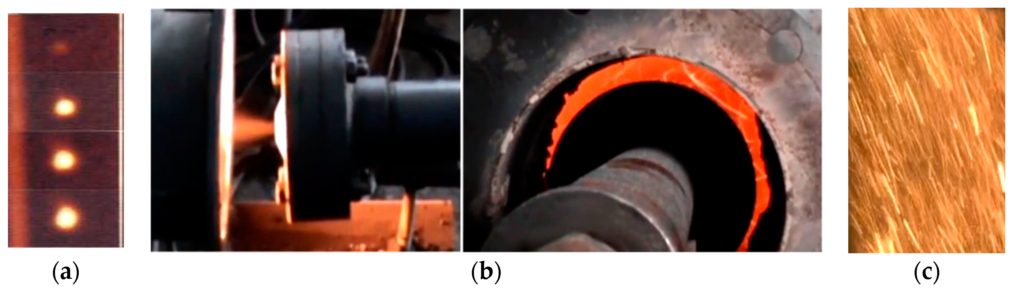
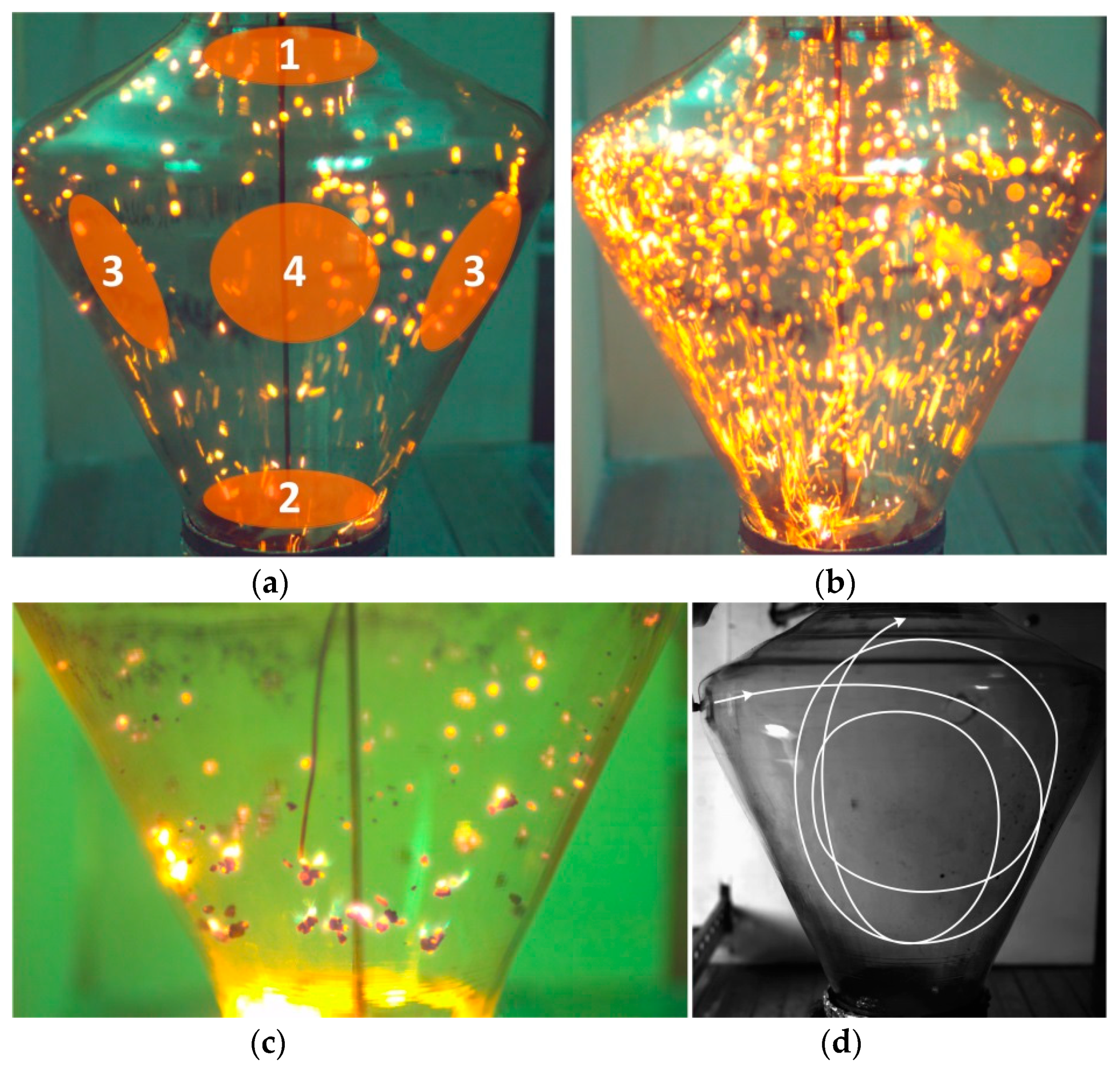
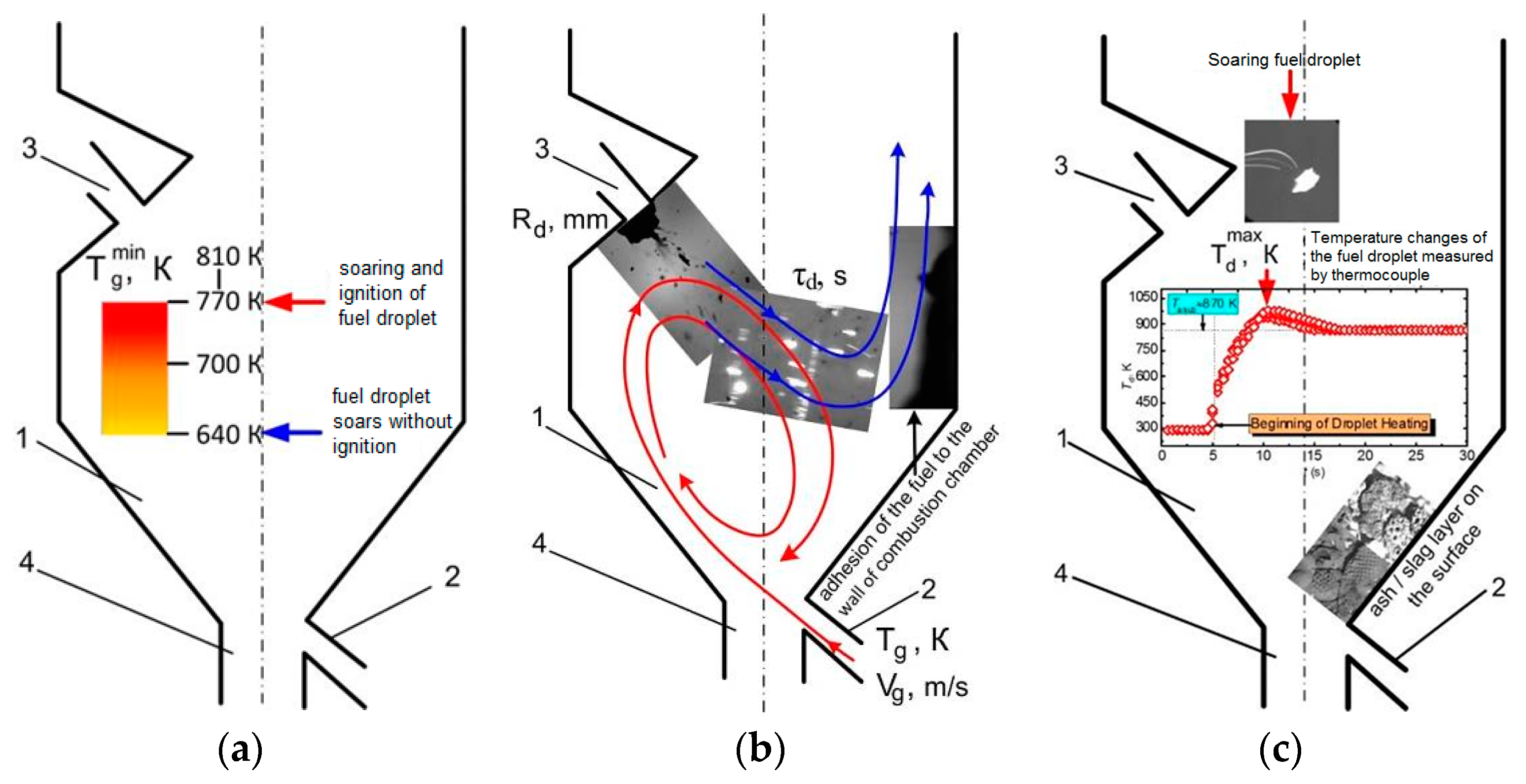
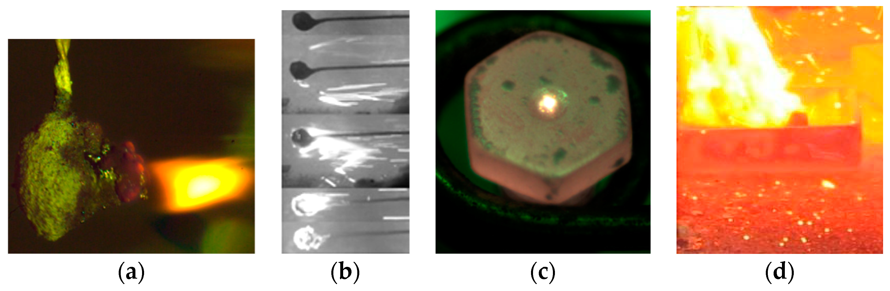
4.2. Modes of Ignition and Combustion of Slurry Fuels
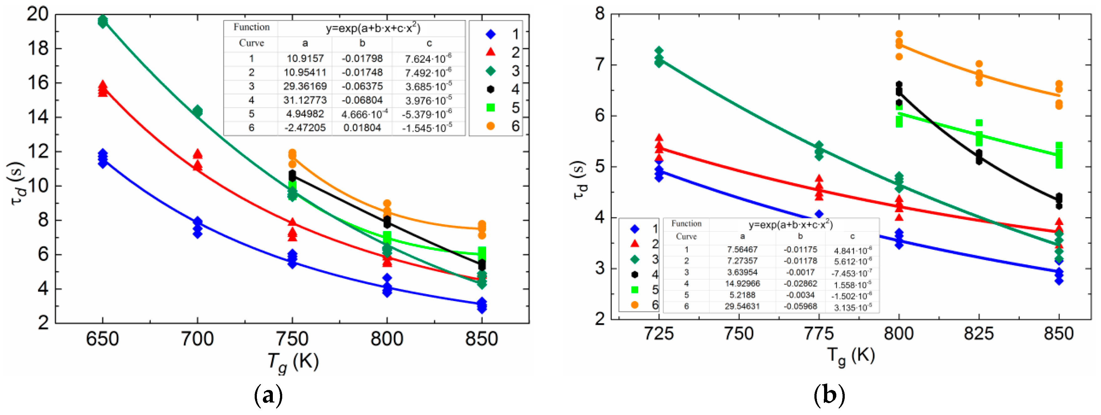
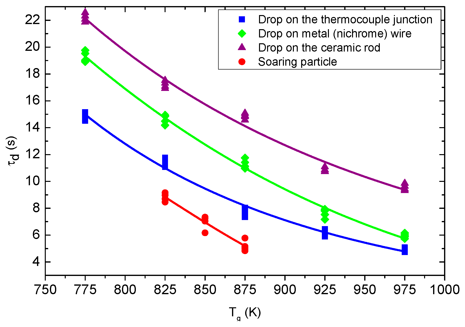
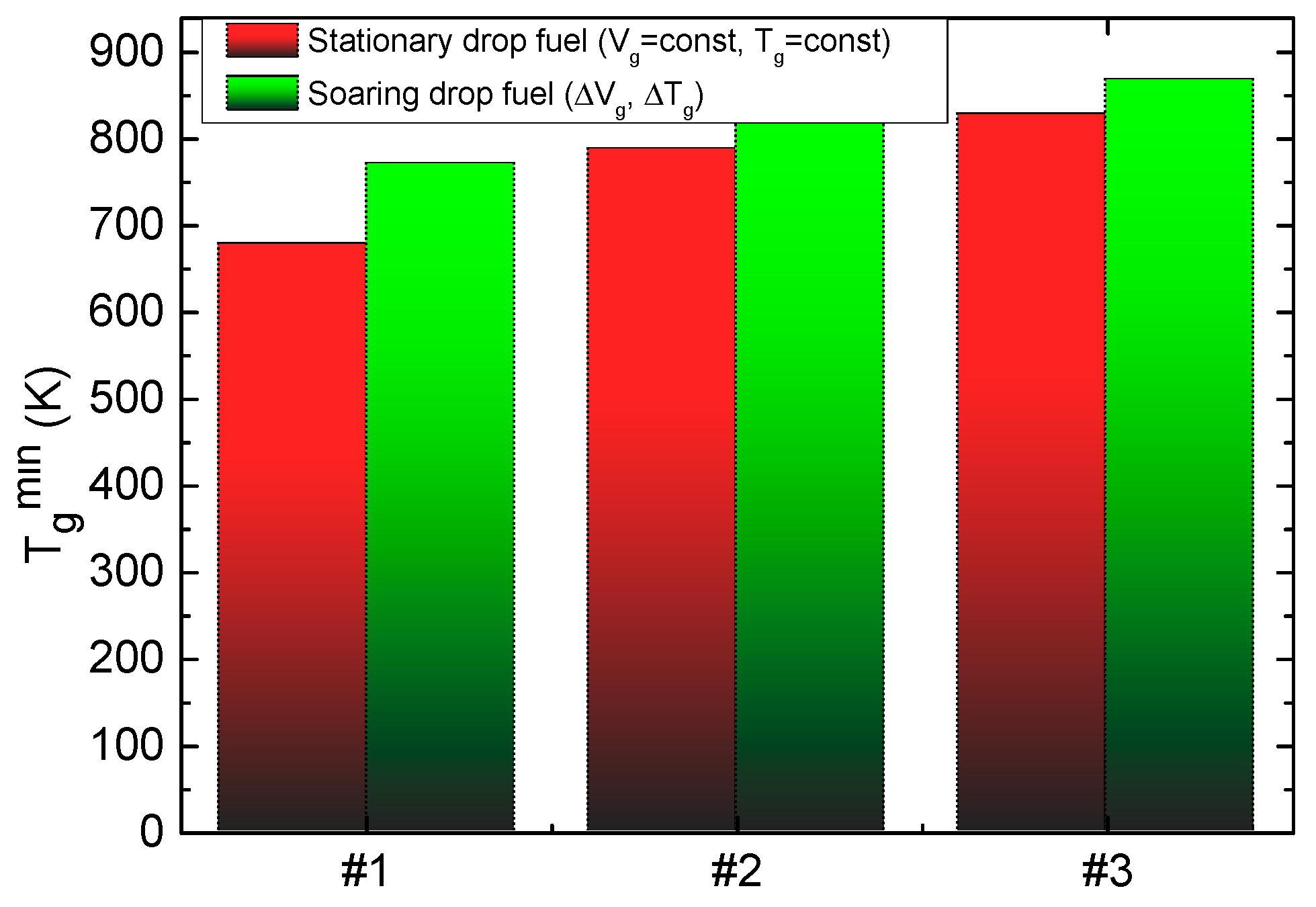
4.3. Differences in the Characteristics of Ignition of Slurry Fuel Droplets
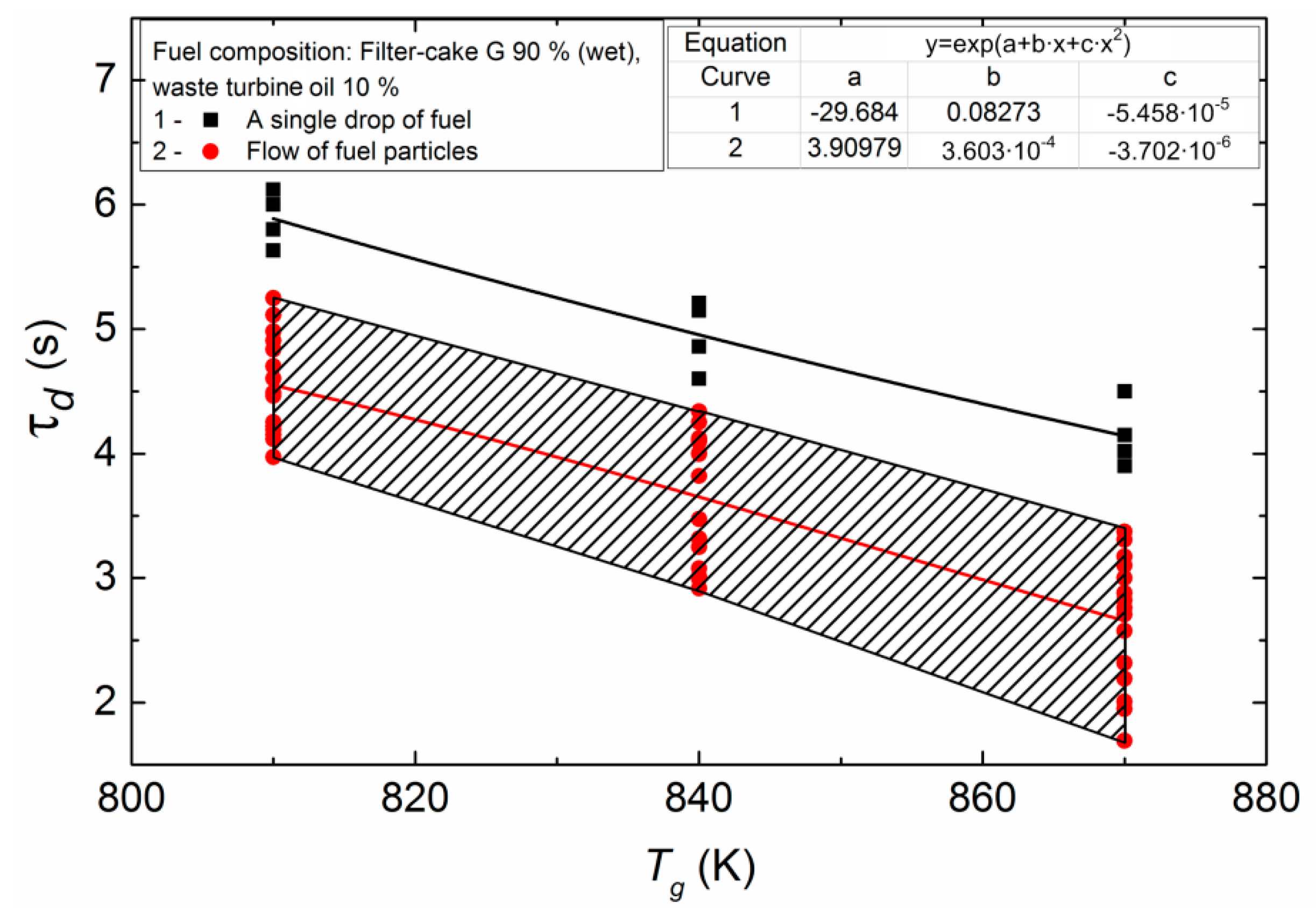
4.4. Comparison of Ignition Characteristics of a Single Droplet and a Polydisperse Flow of Slurry Fuel Droplets
4.5. Recommendations for Applying the Research Results
- (i)
- a small addition (5–10% by relative mass concentration) of brown coal leads to a significant decrease in the ignition delay time and the minimum ignition temperatures of the soaring droplets of CLF; similar conclusions can be made from experiments with addition of enriched coal to the waste coal;
- (ii)
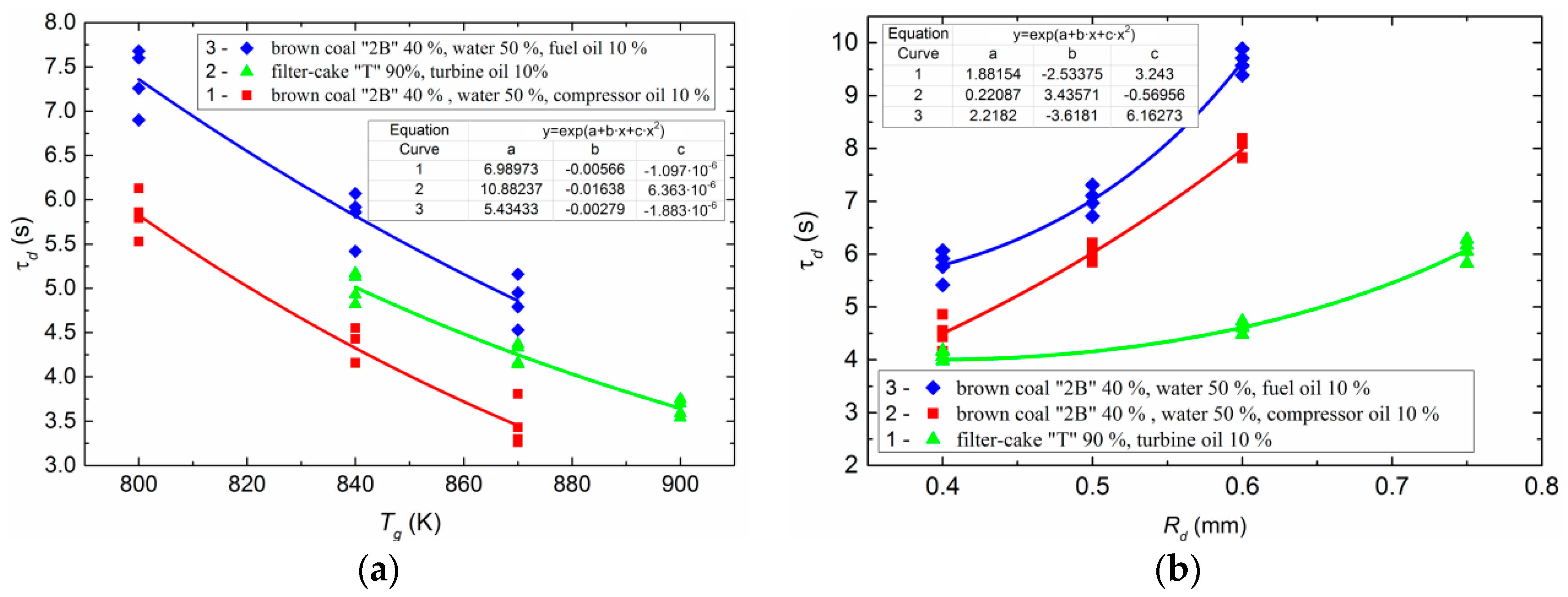
- an increase in the mass fraction of water (from 40 to 50%) in the CLF composition leads to a significant increase in the ignition delay time (on average by 30–40%) of the soaring fuel droplets in the combustion chamber [29];
- (iii)
- adding, for example, up to 5% of aluminum powder [30] to CLF composition has a positive effect on the combustion stabilization and the combustion temperature increase;
- (iv)
- the use of CLF compositions with plant additives, for example, rapeseed oil, allows strengthening the main integral parameters of combustion and reducing the concentration of harmful emissions [31].
5. Conclusions
- (i)
- An experimental setup with a model combustion chamber has been developed to study the ignition and combustion of soaring CLF droplets in the heated air flow in the conditions close to combustion processes in thermal power plants.
- (ii)
- Four ignition modes of CLF droplets characterized by involuntary motion trajectory and locality of ignition have been established; two of them correspond to the mode of soaring in the heated air flow.
- (iii)
- It is shown that the ignition delay times are lower (up to 2–4 s) for the soaring CLF droplets than when initiating combustion on a fast thermocouple or even when using a material with low temperature diffusivity. In this case, the minimum (threshold) ignition temperature for the soaring CLF droplets is slightly higher than when they are heated on the holders.
- (iv)
- It has been proved that ignition of polydisperse flow of soaring CLF droplets occurs faster than that of a single droplet with ignition delay times lower by 20–40%.
- (v)
- The expediency of using composite slurry fuels based on coal and oil wastes of various power plants and mechanisms as an alternative fuel for boiler combustion has been illustrated.
Author Contributions
Funding
Acknowledgments
Conflicts of Interest
Abbreviations
| CLF | composite liquid fuels |
| CWS | coal-water slurries |
| Nomenclature | |
| Tg | temperature in combustion chamber (K) |
| Vg | air flow rate (m/s) |
| Rd | initial droplet radius (mm) |
| Wa | humidity of original sample (%) |
| Ad | ash level of dry sample (%) |
| Vdaf | yield of volatiles of filter cake converted to a dry ash-free state (s) |
| Qas | heat of combustion (MJ/kg) |
| Tf | flash point (K) |
| Tign | temperature of ignition (K) |
| Tgmin | minimum oxidizer temperature sufficient for sustainable ignition (K) |
| τd | ignition time delay (s) |
| dtr | tube diameter corresponding to inlet diameter of the cone (mm) |
| Va | flow rate of high-pressure fan (L/min) |
| d | droplet diameter (mm) |
| dd | droplet diameter considering spherical shape factor (mm) |
| ε | porosity (relative share of volume not filled by solid phase) |
| bulk density (kg/m3) | |
| droplet density (kg/m3) | |
| Reynolds criterion | |
| velocity of soaring (m/s) | |
| air density (kg/m3) | |
| dynamic viscosity of air (Pa·s) | |
| Ar | Archimedes criterion |
| kinematic viscosity coefficient of the medium (m2/s) | |
| φ | spherical shape factor of the droplet |
| density of the organic mass of fuel (kg/m3) | |
| carbon content in the fuel (%) | |
| hydrogen content in the fuel (%) | |
| ash content per dry mass of fuel (%) | |
| mass air flow rate (g/min) | |
| ϖ | air velocity in the channel (m/s) |
| F | cross-sectional area of the input channel (m2) |
| ash frame density (kg/m3) | |
| true ash density (kg/m3) | |
| large cone diameter (mm) | |
References
- Osintsev, K.V. Studying flame combustion of coal-water slurries in the furnaces of power-generating boilers. Therm. Eng. 2012, 59, 439–445. [Google Scholar] [CrossRef]
- Salomatov, V.V.; Dorokhova, U.V.; Syrodoy, S.V. Transfer of low power boilers to coal-water technology. Polzunovskii Vestnik 2013, 4, 38–46. [Google Scholar]
- Puzyrev, E.M.; Golubev, V.A. Technology of coal-water fuel combustion in power boilers. Vestnik Altaiskoy Nauki 2014, 4, 325–331. [Google Scholar]
- Puzyrev, E.M.; Murko, V.I.; Chernetskii, M.Y. Results of pilot tests of the fuel oil boiler DKVR 6.5/13 on coal-water fuel. Therm. Eng. 2001, 2, 69–71. [Google Scholar]
- Tsepenok, A.I.; Ovchinnikov, Y.V.; Lutsenko, S.V.; Kvrivishvili, A.R.; Lavrinenko, A.A.; Mezhov, E.A. Numerical Studies of the Combustion of Composite CWF in the Boiler DKVR-20-13; Reports of VIII All-Russian Conference “Combustion of Solid Fuel”; Kutateladze Institute of Thermophysics SB RAS: Novosibirsk, Russia, 2012. [Google Scholar]
- Shtym, A.N.; Shtym, K.A.; Vorotnikov, E.G.; Rasputin, O.V. Study and development of vortical technology of fuel burning. Bull. Far East. Fed. Univ. 2010, 2, 43–59. [Google Scholar]
- Ovchinnikov, Y.V.; Boiko, E.E.; Serant, F.A. Problems of combustion of hydrocarbon fuels and proposals on the development of combustion technologies. Proc. Acad. High. Sch. Russ. Fed. 2015, 1, 26. [Google Scholar]
- Ovchinnikov, Y.V.; Boiko, E.E. The Technology of Obtaining and Studying Fine-Dispersed Coal-Water Slurry: Monograph; NSTU Publisher: Novosibirsk, Russia, 2017; p. 308. [Google Scholar]
- Murko, V.I.; Riestor, A.; Tsetsorina, S.A.; Fedyaev, V.I.; Karpenok, V.I. Results of numerical simulation of combustion of coal-water fuel. Polzunovskii Vestnik 2013, 4, 38–46. [Google Scholar]
- Murko, V.I.; Senchurova, Y.A.; Fedyaev, V.I.; Karpenok, V.I. Study of combustion technology of coal slurry fuel in a vortex chamber. Bull. Kuzbass State Tech. Univ. 2013, 2, 103–105. [Google Scholar]
- Kijo-Kleczkowska, A. Combustion of coal-water suspensions. Fuel 2011, 90, 865–877. [Google Scholar] [CrossRef]
- Glushkov, D.O.; Strizhak, P.A.; Chernetskii, M.Y. Organic coal-water: Problems and advances (Review). Ther. Eng. 2016, 63, 707–717. [Google Scholar] [CrossRef]
- Glushkov, D.O.; Strizhak, P.A.; Vershinina, K.Y. Minimum temperatures for sustainable ignition of coal water slurry containing petrochemicals. Appl. Ther. Eng. 2016, 96, 534–546. [Google Scholar] [CrossRef]
- Vershinina, K.Y.; Iegorov, R.I.; Strizhak, P.A. The ignition parameters of the coal-water slurry droplets at the different methods of injection into the hot oxidant flow. Appl. Ther. Eng. 2016, 107, 10–20. [Google Scholar] [CrossRef]
- Glushkov, D.O.; Strizhak, P.A.; Vershinina, K.Y. Hot surface ignition of a composite fuel droplet. MATEC Web Conf. 2015, 23, 1–4. [Google Scholar] [CrossRef]
- Fedorova, N.I.; Patrakov, Y.F.; Surkov, V.G.; Golovko, A.K. Analysis of the nature of combustion of composite fuels, obtained by cavitation method. Bull. Kuzbass State Tech. Univ. 2007, 4, 38–41. [Google Scholar]
- Atal, A.; Levendis, Y.A. Observations on the combustion behavior of coal water fuels and coal water fuels impregnated with calcium magnesium acetate. Combust. Flame 1993, 93, 61–89. [Google Scholar] [CrossRef]
- Atal, A.; Levendis, Y.A. Combustion of CWF agglomerates from pulverized or micronized bituminous coal, carbon black, and diesel soot. Combust. Flame 1994, 93, 326–342. [Google Scholar] [CrossRef]
- Baskakov, A.P.; Mukhlenov, I.P.; Sazhin, B.S.; Frolov, V.F. Calculations of Fluidized-Bed Apparatuses: Reference Book; Khimiya: Leningrad, Russia, 1986; p. 352. [Google Scholar]
- Aerov, M.E.; Todes, O.M. Hydraulic and Thermal Bases of Operation of Devices with Stationary and Boiling Granular Layer; Khimiya: Leningrad, Russia, 1968; p. 247. [Google Scholar]
- Pavlov, K.F.; Romankov, P.G.; Noskov, A.A. Examples and Problems of the Course on Processes and Devices of Chemical Technology; Khimiya: Leningrad, Russia, 1976; p. 552. [Google Scholar]
- Vargaftik, N.B. Handbook of Thermophysical Properties of Gases and Liquids; Nauka: Moscow, Russia, 1972; p. 720. [Google Scholar]
- Sukhorukov, V.I. Scientific Bases of the Improvement of Equipment and Technologies for the Production of Coke; ALLO: Yekaterinburg, Russia, 1999; p. 393. [Google Scholar]
- Guva, A.Y. Brief Thermophysical Handbook; Sibvuzizdat: Novosibirsk, Russia, 2002; p. 300. [Google Scholar]
- Antonov, P.P.; Sidorov, A.M.; Tyurkin, A.S.; Shcherbakov, F.V. Revised thermal calculation of furnaces of low-temperature fluidized bed. Polzunovskii Vestnik 2008, 1–2, 115–122. [Google Scholar]
- Pavlenko, S.I. Fine-Grained Concrete from Industrial Waste; ASV: Moscow, Russia, 1997; p. 176. [Google Scholar]
- Glushkov, D.O.; Lyrshchikov, S.Y.; Shevyrev, S.A.; Strizhak, P.A. Burning Properties of Slurry Based on Coal and Oil Processing Waste. Energy Fuels 2016, 30, 3441–3450. [Google Scholar] [CrossRef]
- Valiullin, T.R.; Strizhak, P.A. Influence of the shape of soaring particle based on coal-water slurry containing petrochemicals on ignition characteristics. Ther. Sci. 2017, 21, 1399–1408. [Google Scholar] [CrossRef]
- Glushkov, D.O.; Syrodoy, S.V.; Zakharevich, A.V.; Strizhak, P.A. Ignition of promising coal-water slurry containing petrochemicals: Analysis of key aspects. Fuel Process. Technol. 2016, 148, 224–235. [Google Scholar] [CrossRef]
- Egorov, R.I.; Valiullin, T.R.; Strizhak, P.A. Energetic and ecological effect of small amount of metalline powders at the doping of the waste-derived fuels. Combust. Flame 2018, 193, 335–343. [Google Scholar] [CrossRef]
- Nyashina, G.S.; Vershinina, K.Y.; Dmitrienko, M.A.; Strizhak, P.A. Environmental benefits and drawbacks of composite fuels based on industrial wastes and different ranks of coal. J. Hazard Mater. 2018, 347, 359–370. [Google Scholar] [CrossRef] [PubMed]


| No. | Parameter | Value | Comment |
|---|---|---|---|
| 1 | Initial diameter of the cone (dtr), mm | 80 | The pipe diameter (dtr) corresponds to the initial diameter of the cone |
| 2 | High pressure fan flow rate at 293 K (Va), L/min | 1200 | Swirl fan Leister Robust (50 Hz) |
| 3 | Droplet diameter (d), mm | 1.5 | Without the sphericity coefficient |
| 4 | Initial air temperature (for igniting a fuel droplet), K | 753 | - |
| 5 | Nominal (maximum) air temperature, K | 923 | - |
| 6 | Humidity of an initial fuel droplet (Wa), %wt. | 43.5 | - |
| 7 | Ash content of an initial fuel droplet (Ad), %wt. | 25 | - |
| Density, kg/m3 | 0.43 |
| Dynamic coefficient of viscosity, Pa·s | 376 × 10−7 |
| Sample | Wa, % | Ad, % | Vdaf, % | Qas, MJ/kg |
|---|---|---|---|---|
| Brown coal | 14.11 | 4.12 | 47.63 | 22.91 |
| Filter-cake “T” | – | 21.20 | 16.09 | 26.92 |
| Filter-cake “K” | – | 26.46 | 23.08 | 24.83 |
| Sample | Density at 293 K, kg/m3 | Wa, % | Ad, % | Tf, K | Tign, K | Qas, MJ/kg |
|---|---|---|---|---|---|---|
| Used turbine oil | 868 | – | 0.03 | 448 | 466 | 44.99 |
| Fuel oil | 1000 | 6.12 | 4.06 | 438 | 513 | 39.4 |
| Used compressor oil | 887 | – | 0.023 | 458 | 502 | 45.2 |
| Composition No. | Solid Components (%) | Liquid Fuel Components (%) | Water (%) | Plasticizer (%) | |||||
|---|---|---|---|---|---|---|---|---|---|
| Coal “2B” | Filter-Cake “K” | Filter-Cake “G” | Waste Engine Oil | Waste Turbine Oil | Waste Compressor Oil | Fuel Oil | |||
| 1 | 50 | - | - | 10 | - | - | - | 39.5 | 0.5 |
| 2 | 50 | - | - | - | 10 | - | - | 39.5 | 0.5 |
| 3 | 40 | - | - | - | - | 10 | - | 50 | - |
| 4 | - | - | 50 | - | - | - | 10 | 39 | 1 |
| 5 | - | 50 | - | 10 | - | - | - | 39.5 | 0.5 |
| 6 | - | 50 | - | - | 10 | - | - | 39.5 | 0.5 |
© 2019 by the authors. Licensee MDPI, Basel, Switzerland. This article is an open access article distributed under the terms and conditions of the Creative Commons Attribution (CC BY) license (http://creativecommons.org/licenses/by/4.0/).
Share and Cite
Bogomolov, A.; Valiullin, T.; Vershinina, K.; Shevyrev, S.; Shlegel, N. Igniting Soaring Droplets of Promising Fuel Slurries. Energies 2019, 12, 208. https://doi.org/10.3390/en12020208
Bogomolov A, Valiullin T, Vershinina K, Shevyrev S, Shlegel N. Igniting Soaring Droplets of Promising Fuel Slurries. Energies. 2019; 12(2):208. https://doi.org/10.3390/en12020208
Chicago/Turabian StyleBogomolov, Alexander, Timur Valiullin, Ksenia Vershinina, Sergey Shevyrev, and Nikita Shlegel. 2019. "Igniting Soaring Droplets of Promising Fuel Slurries" Energies 12, no. 2: 208. https://doi.org/10.3390/en12020208
APA StyleBogomolov, A., Valiullin, T., Vershinina, K., Shevyrev, S., & Shlegel, N. (2019). Igniting Soaring Droplets of Promising Fuel Slurries. Energies, 12(2), 208. https://doi.org/10.3390/en12020208