Speed Control for Turbine-Generator of ORC Power Generation System and Experimental Implementation


Abstract
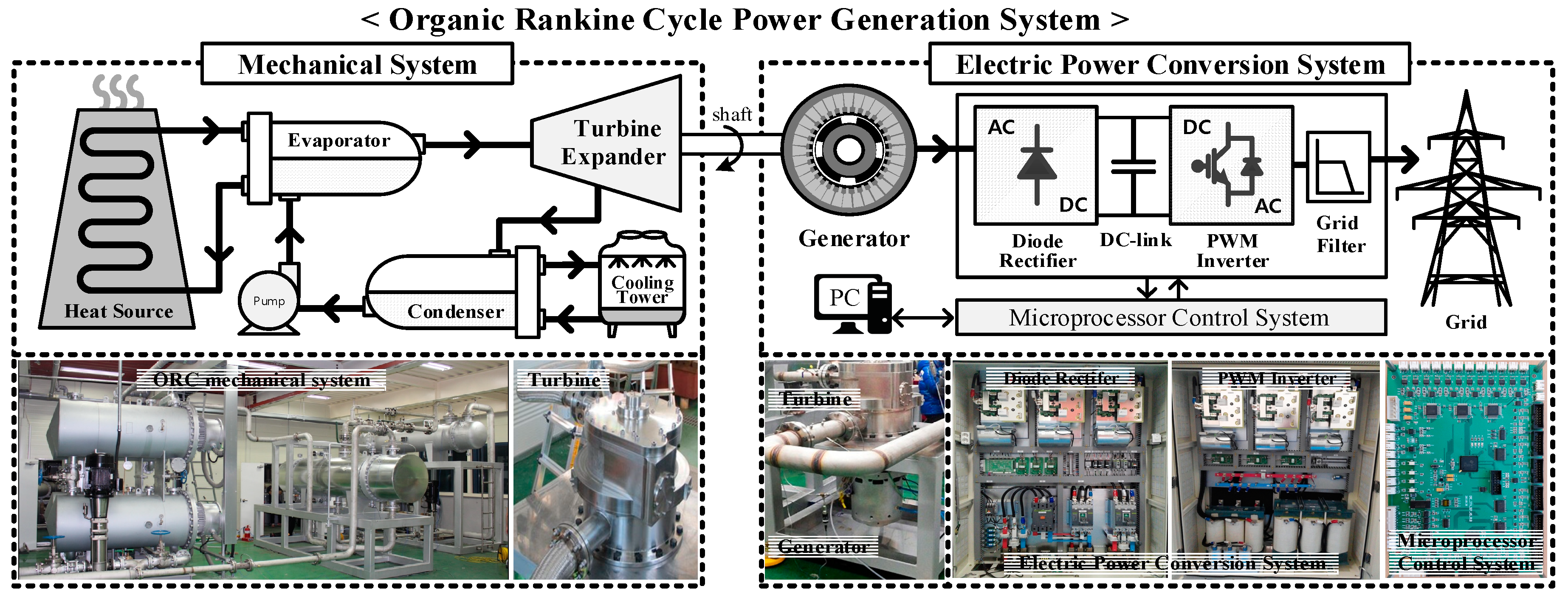
1. Introduction
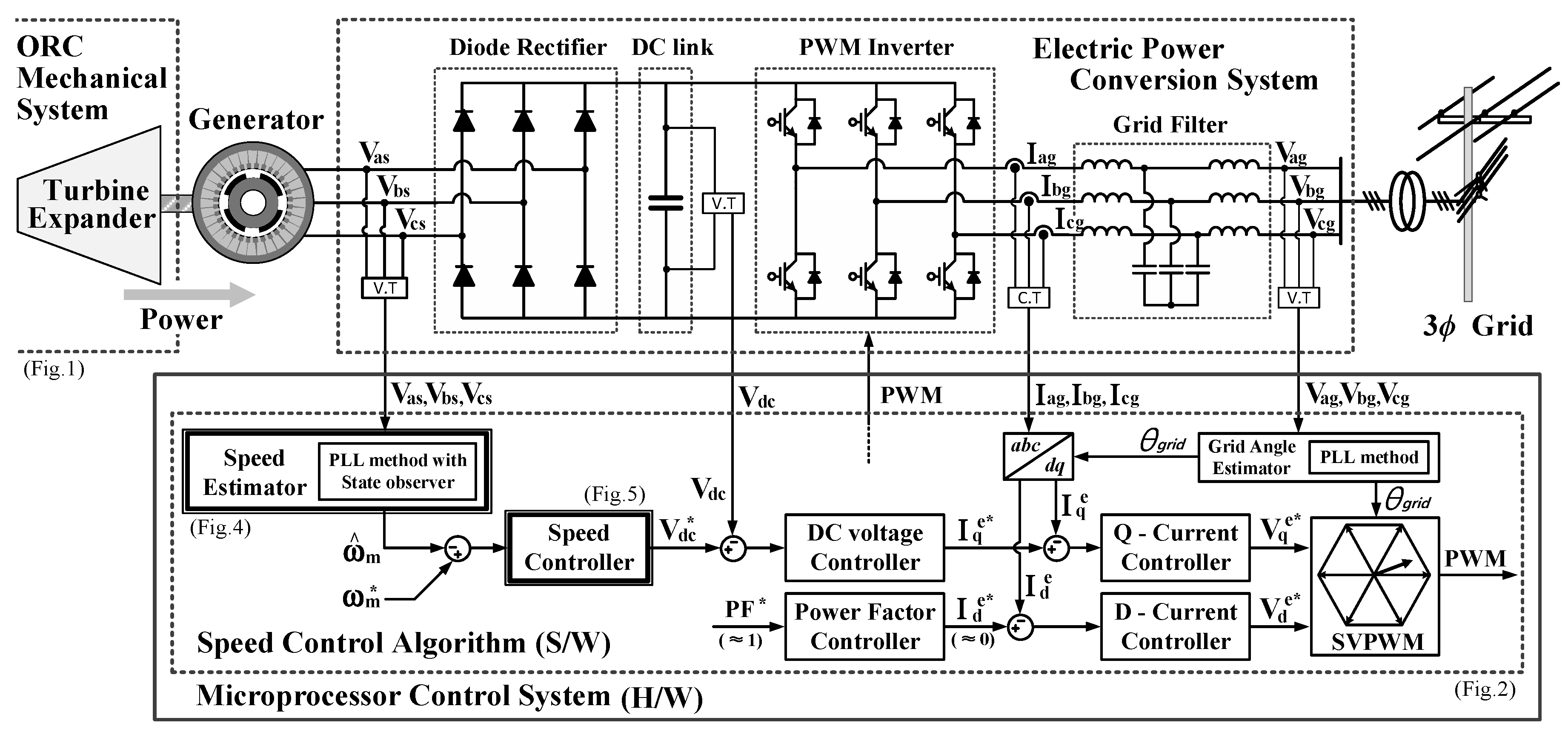
2. Grid-Connected Electric Power Conversion System
3. Speed Estimation and Control for Turbine and Generator
3.1. Speed Estimation Using PLL
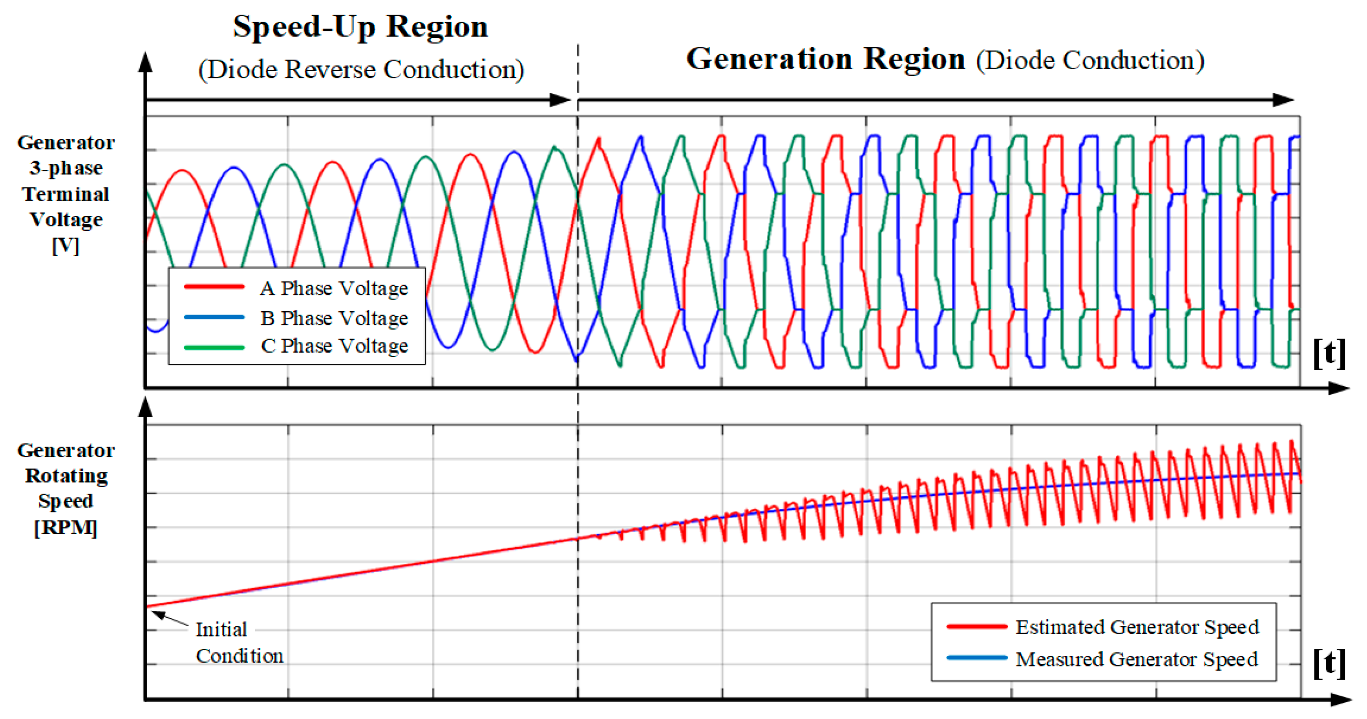
3.2. Indirect Speed Control
4. Experimental Set-Up and Results
5. Conclusions
Author Contributions
Funding
Conflicts of Interest
References
- Larjola, J. Electricity from industrial waste heat using high-speed organic Rankine cycle (ORC). Int. J. Prod. Econ. 1995, 41, 227–235. [Google Scholar] [CrossRef]
- Hung, T.C.; Shai, T.Y.; Wang, S.K. A review of organic Rankine cycles (ORCs) for the recovery of low-grade waste heat. Energy 1997, 22, 661–667. [Google Scholar] [CrossRef]
- Curtiss, P.S.; Kreider, J.F. Recent developments in the control of distributed electrical generation systems. ASME J. Sol. Energy Eng. 2003, 125, 352–358. [Google Scholar] [CrossRef]
- Lawrence, R.; Middlekauff, S. The new guy on the block. IEEE Ind. Appl. Mag. 2005, 11, 54–59. [Google Scholar] [CrossRef]
- Papini, F.; Bolognesi, P. Preliminary design and analysis of a high speed permanent magnets synchronous generator. In Proceedings of the IEEE MELECON 2010, Valletta, Malta, 26–28 April 2010. [Google Scholar]
- Quoilin, S.; Broek, M.V.D.; Declaye, S.; Dewallef, P.; Lemort, V. Techno-economic survey of Organic Rankine Cycle (ORC) systems. Renew. Sustain. Energy Rev. 2013, 22, 168–186. [Google Scholar] [CrossRef]
- Colonna, P.; Casati, E.; Trapp, C.; Mathijssen, T.; Larjola, J.; Turunen-Saarest, T.; Uusitalo, A. Organic Rankine cycle power systems: From the concept to current technology, applications, and an outlook to the future. ASME J. Eng. Gas Turbines Power 2015, 137, 100801. [Google Scholar] [CrossRef]
- Petrovic, V.; Ortega, R.; Stankovic, A.M.; Tadmor, G. Design and implementation of an adaptive controller for torque ripple minimization in PM synchronous motors. IEEE Trans Power Electron. 2000, 15, 871–880. [Google Scholar] [CrossRef]
- Bojoi, R.; Pastorelli, M.; Bottomley, J.; Giangrande, P.; Gerada, C. Sensorless Control of PM Motor Drives—A Technology Status Review. In Proceedings of the IEEE WEMDCD 2013, Paris, France, 11–12 March 2013. [Google Scholar]
- Holtz, J. Developments in sensorless AC drive technology. In Proceedings of the IEEE PEDS 2005, Kuala Lumpur, Malaysia, 28 November–1 December 2005. [Google Scholar]
- Islam, M.N.; Seethaler, R.J. Sensorless position control for piezoelectric actuators using a hybrid position observer. IEEE/ASME Trans. Mechatron. 2014, 19, 667–675. [Google Scholar] [CrossRef]
- Xu, G.; Liu, F.; Hu, J.; Bi, T. Coordination of wind turbines and synchronous generators for system frequency control. Renew. Energy 2018, 129, 225–236. [Google Scholar] [CrossRef]
- Alcalá, J.; Cárdenas, V.; Espinozac, J.; Duránaa, M. Investigation on the limitation of the BTB-VSC converter to control the active and reactive power flow. Electr. Power Syst. Res. 2017, 143, 149–162. [Google Scholar] [CrossRef]
- Bunjongjit, K.; Kumsuwan, Y.; Sriuthaisiriwong, Y. An implementation of three-level BTB NPC voltage source converter based-PMSG wind energy conversion system. In Proceedings of the IEEE TENCON 2014, Bangkok, Thailand, 22–25 October 2014. [Google Scholar]
- Vilathgamuwa, D.M.; Jayasinghe, S.D.G. Rectifier systems for variable speed wind generation—A review. In Proceedings of the IEEE ISIE 2012, Hangzhou, China, 28–31 May 2012. [Google Scholar]
- Tan, K.; Islam, S. Optimum control strategies in energy conversion of PMSG wind turbine system without mechanical sensors. IEEE Trans. Energy Convers. 2004, 19, 392–399. [Google Scholar] [CrossRef]
- Binder, A.; Schneider, T. Permanent magnet synchronous generators for regenerative energy conversion—A survey. In Proceedings of the IEEE EPE 2005, Dresden, Germany, 11–14 September 2005. [Google Scholar]
- Rodriguez, J.; Franquelo, L.G.; Kouro, S.; Leon, J.I.; Portillo, R.C.; Prats, M.A.M.; Perez, M.A. Multilevel converters: An enabling technology for high-power applications. Proc. IEEE 2009, 97, 1786–1817. [Google Scholar] [CrossRef]
- Rahimi, M. Modeling, control and stability analysis of grid connected PMSG based wind turbine assisted with diode rectifier and boost converter. Electr. Power Energy Syst. 2017, 93, 84–96. [Google Scholar] [CrossRef]
- Aziz, A.; Mto, A.; Stojcevski, A. Full converter based wind turbine generator system generic modelling: Variations and applicability. Sustain. Energy Technol. Assess. 2016, 14, 46–62. [Google Scholar] [CrossRef]
- Kazmierkowski, M.P.; Malesani, L. Current control techniques for three-phase voltage-source PWM converters: A survey. IEEE Trans. Ind. Electron. 1998, 45, 691–703. [Google Scholar] [CrossRef]
- Pozzebon, G.G.; Goncalves, A.F.Q.; Pena, G.G.; Mocambique, N.E.M.; Machado, R.Q. Operation of a three-phase power converter connected to a distribution system. IEEE Trans. Ind. Electron. 2013, 60, 1810–1818. [Google Scholar] [CrossRef]
- Song, S.-H.; Kang, S.-I.; Hahm, N.-K. Implementation and control of grid connected AC-DC-AC power converter for variable speed wind energy conversion system. In Proceedings of the IEEE APEC 2003, Miami Beach, FL, USA, 9–13 February 2003. [Google Scholar]
- Prodanovic, M.; Green, T.C. Control and filter design of three-phase inverters for high power quality grid connection. IEEE Trans. Power Electron. 2013, 18, 373–380. [Google Scholar] [CrossRef]
- Twining, E.; Holmes, D.G. Grid current regulation of a three-phase voltage source inverter with an LCL input filter. IEEE Trans. Power Electron. 2003, 18, 888–895. [Google Scholar] [CrossRef]
- Blaabjerg, F.; Teodorescu, R.; Liserre, M.; Timbus, A.V. Overview of control and grid synchronization for distributed power generation systems. IEEE Trans. Ind. Electron. 2006, 53, 1398–1409. [Google Scholar] [CrossRef]
- Dai, J.C.; Liu, D.; Hu, Y.; Shen, X. Research on joint power and loads control for large scale directly driven wind turbines. ASME J. Sol. Energy Eng. 2013, 136, 021015. [Google Scholar] [CrossRef]
- Svensson, J.; Lindgren, M. Vector current controlled grid connected voltage source converter-influence of non-linearities on the performance. In Proceedings of the IEEE PESC Record, Fukuoka, Japan, 22–22 May 1998. [Google Scholar]
- Van der Broeck, H.W.; Skudelny, H.C.; Stanke, G.V. Analysis and realization of a pulse width modulator based on voltage space vectors. IEEE Trans. Ind. Appl. 1988, 24, 142–150. [Google Scholar] [CrossRef]
- Chung, S.-K. Phase-locked loop for grid-connected three-phase power conversion systems. IEE Proc. Electr. Power Appl. 2000, 147, 213–219. [Google Scholar] [CrossRef]
- Kaura, V.; Blasko, V. Operation of a phase locked loop system under distorted utility conditions. IEEE Trans. Ind. Appl. 1997, 33, 58–63. [Google Scholar] [CrossRef]
- Nash, G. Phase-Locked Loop Design Fundamentals. Motorola Application Note AN-535 1994.
- Hsieh, G.; Hung, J.C. Phase-Locked Loop Techniques—A Survey. IEEE Trans. Lnd. Electron. 1996, 43, 609–615. [Google Scholar] [CrossRef]
- Chung, S.-K. A phase tracking system for three phase utility interface inverters. IEEE Trans. Power Electron. 2000, 15, 431–438. [Google Scholar] [CrossRef]
- Amuda, L.N.; Cardoso Filho, B.J.; Silva, S.M.; Silva, S.R.; Diniz, A.S.A.C. Wide bandwidth single and three-phase PLL structures for grid-tied PV systems. In Proceedings of the IEEE PVSC, Anchorage, AK, USA, 15–22 September 2000. [Google Scholar]
- Nozari, F.; Mezs, P.A.; Julian, A.L.; Sun, C.; Lipo, T.A. Sensorless synchronous motor drive for use on commercial transport airplanes. IEEE Trans. Ind. Appl. 1995, 31, 850–859. [Google Scholar] [CrossRef]
- Caliskan, V.; Perreault, D.J.; Jahns, T.M.; Kassakian, J.G. Analysis of three-phase rectifiers with constant-voltage loads. IEEE Trans. Circuits Syst. 2003, 50, 1220–1225. [Google Scholar] [CrossRef]
- Ketzer, M.B.; Jacobina, C.B. Sensorless control technique for PWM rectifiers with voltage disturbance rejection and adaptive power factor. IEEE Trans. Ind. Electron. 2015, 62, 1140–1151. [Google Scholar] [CrossRef]
- Blasko, V.; Moreira, J.C.; Lipo, T.A. A new field oriented controller utilizing spatial position measurement of rotor end ring current. In Proceedings of the IEEE PESC Record, Milwaukee, WI, USA, 26–29 June 1989. [Google Scholar]
- Song, H.; Nam, K. Dual current control scheme for PWM converter under unbalanced input voltage conditions. IEEE Trans. Ind. Electron. 1999, 46, 953–959. [Google Scholar] [CrossRef]
- Limongi, L.R.; Bojoi, R.; Pica, C.; Profumo, F.; Tenconi, A. Analysis and comparison of phase locked loop techniques for grid utility applications. In Proceedings of the IEEE PCCON 2007, Nagoya, Japan, 2–5 April 2007. [Google Scholar]
- Ko, Y.; Park, K.; Lee, K.-B.; Blaabjerg, F. A new PLL system using full order observer and PLL system modeling in a single phase grid-connected inverter. In Proceedings of the IEEE ICPE 2011, Jeju, South Korea, 30 May–3 June 2011. [Google Scholar]
- Freijedo, F.D.; Doval-Gandoy, J.; López, Ó.; Acha, E. A generic open-loop algorithm for three-phase grid voltage/current synchronization with particular reference to phase, frequency, and amplitude estimation. IEEE Trans. Power Electron. 2009, 24, 94–107. [Google Scholar] [CrossRef]
- Fortescue, C. Method of symmetrical coordinates applied to the solution of polyphase networks. Trans. AIEE 1918, 37, 1027–1140. [Google Scholar]
- Yun, E.; Kim, D.; Yoon, S.Y.; Kim, K.C. Experimental investigation of an organic Rankine cycle with multiple expanders used in parallel. Appl. Energy 2015, 145, 246–254. [Google Scholar] [CrossRef]
- Sung, T.; Yun, E.; Kim, H.D.; Yoon, S.Y.; Choi, B.S.; Kim, K.; Kim, J.; Jung, Y.B.; Kim, K.C. Performance characteristics of a 200-kW organic Rankine cycle system in a steel processing plant. Appl. Energy 2016, 183, 623–635. [Google Scholar] [CrossRef]


| System | Parameter | Value |
|---|---|---|
| Converter System | DC-link capacitance | 3133 (uF) |
| Switching frequency | 10 (kHz) | |
| Control period | 100 (us) | |
| Grid-Network | Grid line-line voltage | 55 (Vrms) (4:1 trans.) |
| Frequency | 60 (Hz) | |
| Filter L inductance | 5 (mH) | |
| Simulator/Generator (PMSM/G) | Rated power | 15 (kW)/12 (kW) |
| Rated torque | 95.4 (Nm)/70 (Nm) | |
| Back EMF constant | 109.0 (Vpeak L-L/krpm) | |
| Pole number | 8 |
© 2019 by the authors. Licensee MDPI, Basel, Switzerland. This article is an open access article distributed under the terms and conditions of the Creative Commons Attribution (CC BY) license (http://creativecommons.org/licenses/by/4.0/).
Share and Cite
Park, H.-S.; Heo, H.-J.; Choi, B.-S.; Kim, K.C.; Kim, J.-M. Speed Control for Turbine-Generator of ORC Power Generation System and Experimental Implementation. Energies 2019, 12, 200. https://doi.org/10.3390/en12020200
Park H-S, Heo H-J, Choi B-S, Kim KC, Kim J-M. Speed Control for Turbine-Generator of ORC Power Generation System and Experimental Implementation. Energies. 2019; 12(2):200. https://doi.org/10.3390/en12020200
Chicago/Turabian StylePark, Hyung-Seok, Hong-Jun Heo, Bum-Seog Choi, Kyung Chun Kim, and Jang-Mok Kim. 2019. "Speed Control for Turbine-Generator of ORC Power Generation System and Experimental Implementation" Energies 12, no. 2: 200. https://doi.org/10.3390/en12020200
APA StylePark, H.-S., Heo, H.-J., Choi, B.-S., Kim, K. C., & Kim, J.-M. (2019). Speed Control for Turbine-Generator of ORC Power Generation System and Experimental Implementation. Energies, 12(2), 200. https://doi.org/10.3390/en12020200