1. Introduction
There is abundant wind energy in Northwest China and large-scale wind farms are connected to the grid. Wind energy is transported to the load center through long distance high voltage transmission lines. Since 2009, IEA Wind TCP member countries have increased their wind share in the energy mix at an average rate of 0.44% per year. Wind-generated electricity met almost 5.6% of the world’s demand in 2017 [
1]. The steady increase of wind turbines brings new challenges to the safe and stable operation of the system [
2,
3,
4]. Because of the high power generation efficiency, small capacity of the converter and decoupling control of active power and reactive power, doubly-fed induction generator (DFIG) has become the main model of large-scale wind farms. DFIGs have become a dominant wind turbine (WT) technology, therefore, this paper takes DFIGs as the research object [
5,
6]. However, the rotor speed is decoupled from the system frequency when DFIGs adopt the converter control mode [
7,
8,
9], which reduces the equivalent inertia of the system. When the permeability of wind turbines increases to a certain extent, the dynamic response ability to the system frequency will be greatly declined [
10]. In fact, the rotational speed range of DFIGs is 0.7 pu~1.2 pu, and the rotational kinetic energy stored in the rotor (the blades, hubs, gearboxes and generator rotors of WTs are equivalent to one mass) is much larger than that of a synchronous machine [
11,
12,
13]. If the rotational speed of DFIGs and the system frequency can be coupled, the frequency regulation ability will be greatly improved.
A certain control strategy can make the WTs have a frequency adjustment characteristic similar to that of the synchronous generator, which can control the WTs to participate in the system frequency regulation. The currently applied methods include virtual inertial control and droop control [
14]. Virtual inertial control [
15,
16,
17] and droop control [
18,
19,
20] are additional frequency control modules in the rotor side control system of WTs. WTs usually operate in the Maximum Power Point Tracking (MPPT) mode. Therefore, due to the lack of reserve capacity of WTs, the WTs can only participate in the system frequency regulation in a short time by increasing the virtual inertia. In order to expand the time scale of frequency regulation, the common method is to increase the over speed method [
21,
22,
23,
24] or the pitch angle control method [
25,
26] on the basis of additional frequency control, so WTs obtain a certain reserve capacity to participate in the primary frequency regulation. Although the above methods solve the basic problem of DFIGs participating in system frequency modulation, there are still many detailed problems to be considered for additional frequency control. Due to the droop control coefficient is not easy to determine, the excess coefficient makes it difficult for the system to reach a stable state [
27]. In order to avoid this problem, the relationship among the virtual inertia of DFIGs, the speed regulation and the frequency variation of the grid is discussed in [
28], and the wind power tracing curve is adjusted according to the frequency fluctuation of the system. However, the scheme is slow to respond at the initial time of frequency fluctuation. Therefore, [
29,
30] adopt active power control instead of phase-locked loop (PLL) technology to realize synchronous operation between DFIGs and the grid. Although the response speed and the stability are improved, the control strategy proposed in the above studies only regulates the frequency fluctuation caused by load mutation and the frequency fluctuation in an event of a short-circuit fault is not taken into consideration. There is a clear difference in the frequency fluctuation trend between the load mutation and the short-circuit fault. Therefore, the above methods are not applicable to the frequency regulation when the short-circuit fault occurs.
In view of this situation, the inertia damping characteristics of DFIGs during the whole process of occurrence, development and removal in an event of a short-circuit fault are studied in this paper. On this basis, this paper proposes an improved frequency control strategy for DFIGs. The parameters of additional frequency control are modified according to the variation of the system frequency during the process from fault occurrence to complete removal. The output power of DFIGs is adjusted rapidly with the frequency fluctuation of the system, and the transient stability of the system is improved. Finally, a four-machine two-area simulation model is built in MATLAB/Simulink to verify the effectiveness of the proposed strategy. The results show that after adopting the improved additional frequency control, DFIGs can adjust the rotational speed in time to release the stored kinetic energy to increase the output power once the fault is removed. The proposed method could also effectively reduce the frequency offset, and the improved control method is suitable for different operating conditions.
2. Principle of Conventional Additional Frequency Control for DFIGs
2.1. Conventional Additional Frequency Control Strategy
The power generation and power consumption of the power system are real-time balanced. When the system frequency fluctuates greatly, synchronous generators can respond in time and release or absorb the rotational kinetic energy to damp the system frequency fluctuation, because the rotating speed is closely coupled with the system frequency. Especially in the early stage of the event, the inertia of the generator directly affects the rate of frequency fluctuation and even the stability of the system [
31]. The rotor motion equation of synchronous generators is shown as Equation (1):
where,
H is the inertia constant of the generator; △ω = ω − ω
0, ω is the actual angular velocity,
ω0 is the rated angular velocity;
PM is the mechanical power;
PE is the electromagnetic power;
D is the damping coefficient.
DFIGs usually operate in MPPT mode without the capability of frequency response. When the permeability of WTs is high, in order to improve the frequency dynamic characteristics of the system, additional frequency control such as virtual inertial control is usually added to DFIGs to increase the system inertia.
The conventional additional frequency control method is to add frequency regulation auxiliary power on the basis of MPPT control of WTs. The additional power comes from the kinetic energy released or absorbed by the rotor, as shown in
Figure 1.
where
ωr is the rotor speed;
Pref is the active power reference value of the rotor side converter under the maximum power tracking mode; △
f is the deviation between the system frequency
f and the rated frequency
fN. Additional active power can be expressed as Equation (2):
The form of the equation can be expressed as the follow, which is similar to the rotor motion equation of a conventional synchronous generator:
By comparing Equations (1) and (3), it can be seen that when the differential control coefficient Kd > 0, the rotational inertia is similar to that of a synchronous machine, so differential control is also called inertia control; When the proportional control coefficient Kp > 0, it can increase the damping coefficient and improve the frequency dynamic response ability, so the proportional control is also called droop control.
Because of the different feedback signals, the adjustment processes of inertial control and droop control are different. Inertial control is a transient process, which uses the rate of frequency fluctuation as the feedback signal. It is mainly used to damp the abrupt fluctuation of frequency. Therefore, it can provide a larger active power support at the initial time of the event. But near the frequency extreme point, the rate of frequency fluctuation is close to zero, and the active power support is weak. In contrast, the additional signal of droop control is related to the frequency deviation. In most cases, it is a steady-state process and is mainly used to reduce the frequency deviation of the system. In the process of transient frequency fluctuation caused by various events in the grid, droop control mainly plays a damping role and provides strong active power support near the peak frequency, but the supporting effect is weak at the initial time, so that the control speed is slower than that of inertial control. Effective combination of the rapidity of inertial control and the persistence of droop control can make the system have good dynamic frequency characteristics.
2.2. Limitation Analysis of Conventional Additional Frequency Control under A Short-Circuit Fault
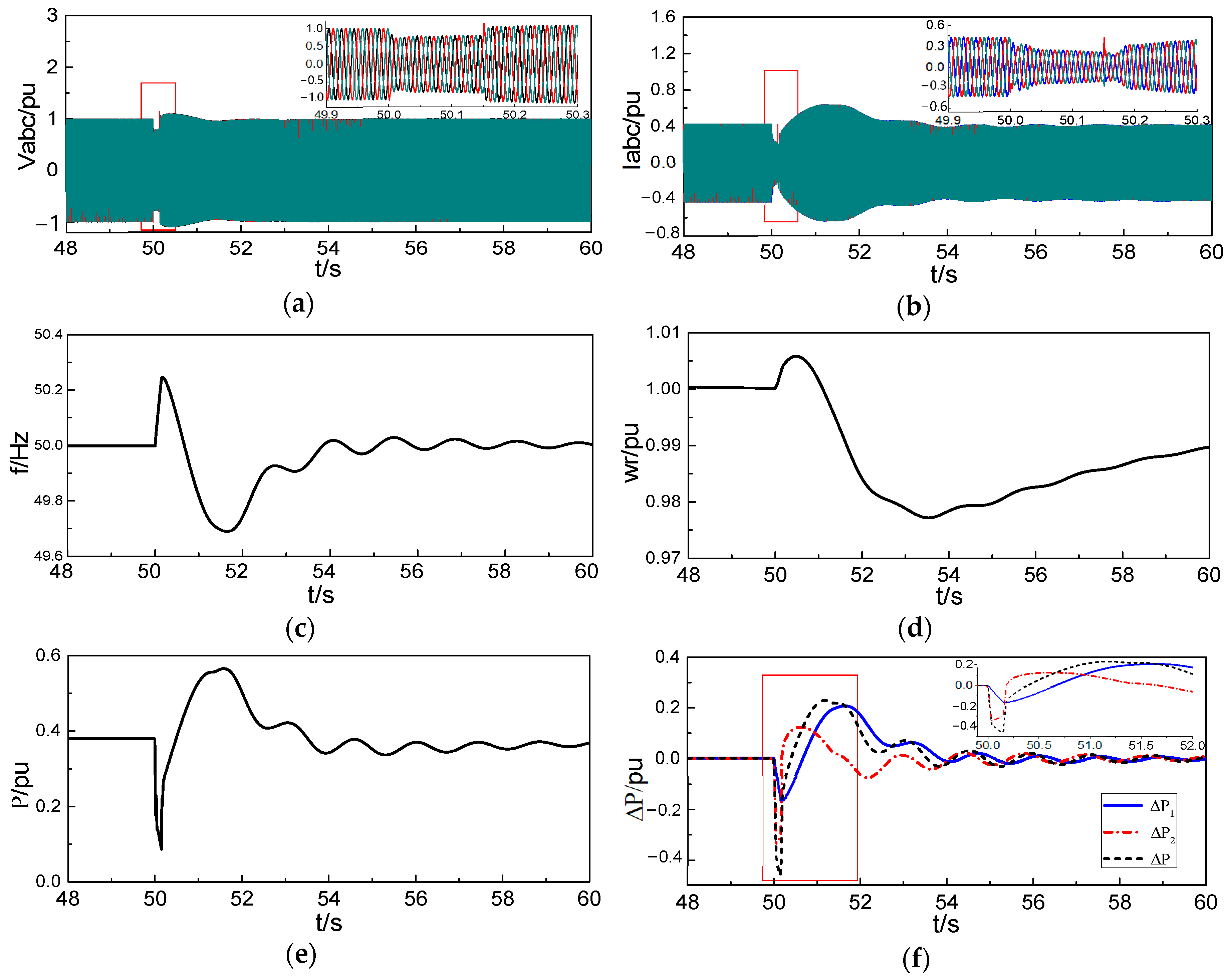
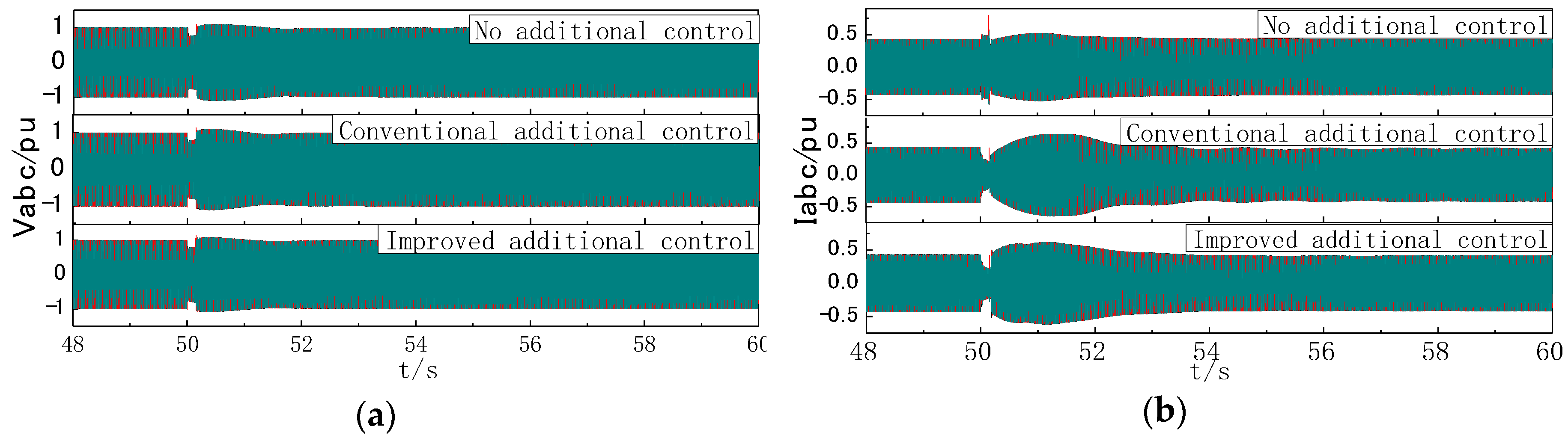
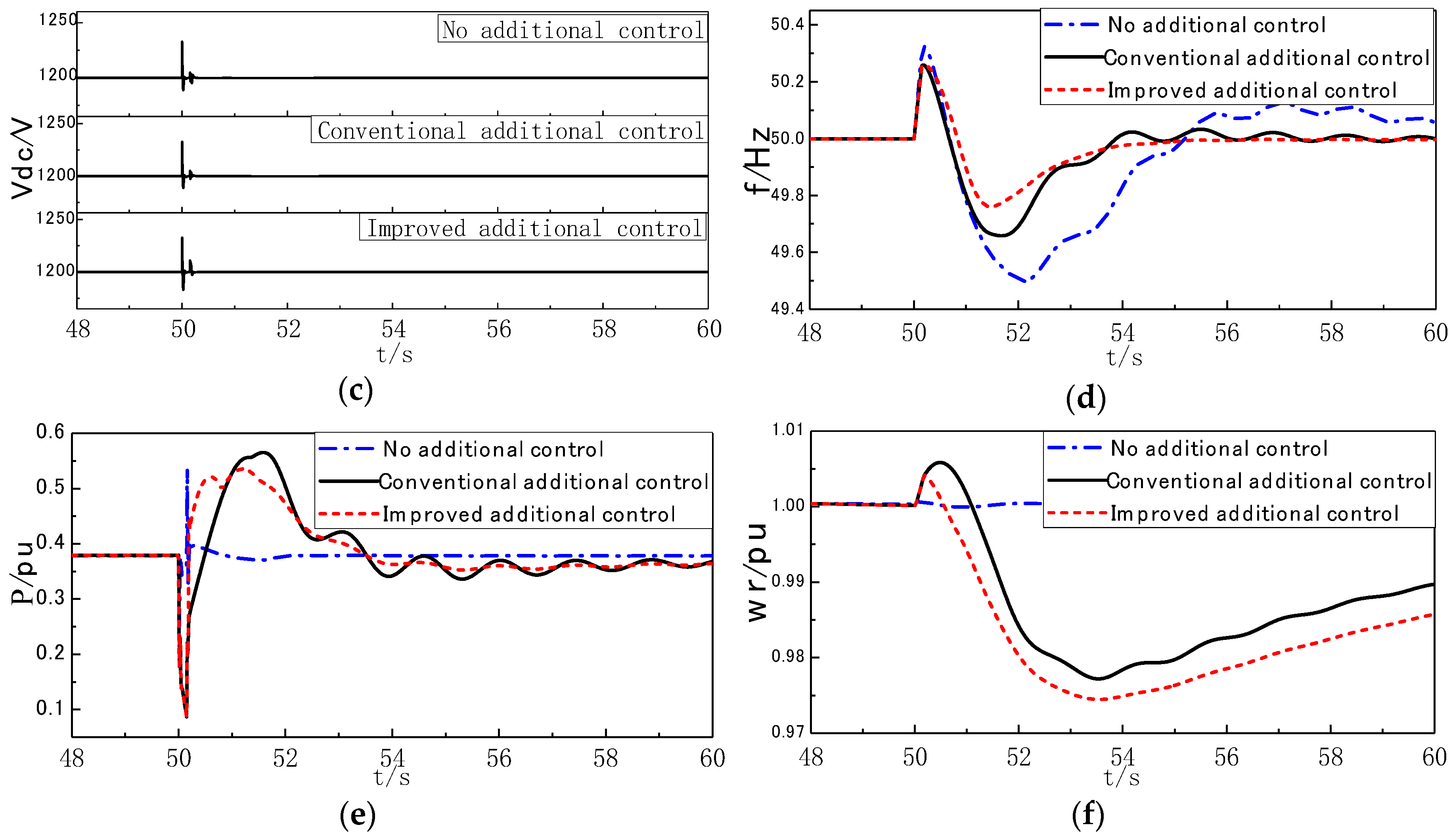
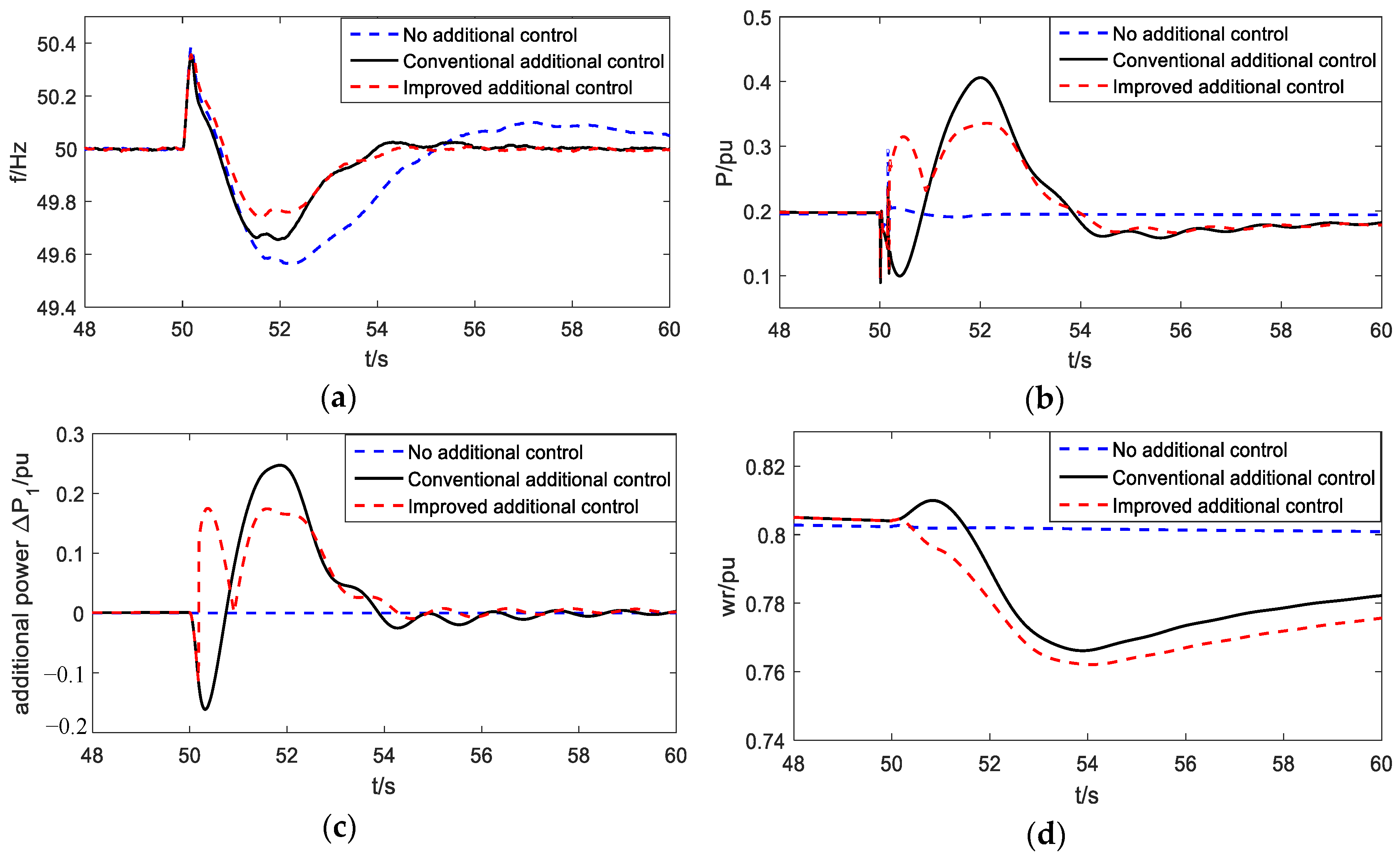
DFIGs are connected to the grid and deliver electrical energy to the load center through high voltage transmission lines. When an instantaneous three-phase short-circuit fault occurs on high voltage transmission lines, the variation of relevant parameters of DFIGs under the condition of conventional additional frequency control is shown in
Figure 2.
In
Figure 2, the short-circuit fault occurs in 50 s. At 50.15 s, the fault is removed. During the period, the lowest terminal voltage of DFIGs falls to 0.75 pu, and the frequency of the system rises sharply during the fault period and falls rapidly after the fault is removed. In this paper, the frequency variation curve is obtained through the simulation in the whole process of fault occurrence, development and removal. The frequency variation trend is similar to that of the permanent-magnet direct-drive wind turbines in the short-circuit fault at the common connection point [
32]. The increase or decrease of load results in the single decrease or increase of the system frequency. But the short-circuit fault will go through two processes of frequency rise and decrease continuously from occurrence to removal.
During the period of frequency rise, the additional power △P1 and△P2 make the reference value of active power on the rotor side smaller. This could control the acceleration of the rotor and absorb the excess active power, which can reduce the output power of the WTs to damp the system frequency rise. Inertial control plays a leading role in the initial time of the short-circuit fault and provides strong power support, while droop control plays a weak role. With the increase of frequency deviation, the additional power of droop control gradually increases. After 0.15 seconds, the fault is removed and the frequency rises to the maximum and then goes down. The active power demand of the system increases instantaneously, and the generators are required to replenish the shortage of active power in time. During this period, the power △P2 produced by inertial control becomes positive, which helps to increase the reference value of active power on the rotor side, but the inertial support function is weak. At this time, the frequency deviation is large, and the power △P1 produced by droop control plays a strong role. But the value is negative and the total additional power is negative, the reference value of active power on the rotor side is still low. The output electromagnetic power of WTs is less than the captured mechanical power, so the rotor keeps the acceleration trend and cannot release kinetic energy to meet the instantaneous surge of active power demand. As the frequency gradually decreases, the additional power eventually becomes positive and the rotor starts to decelerate.
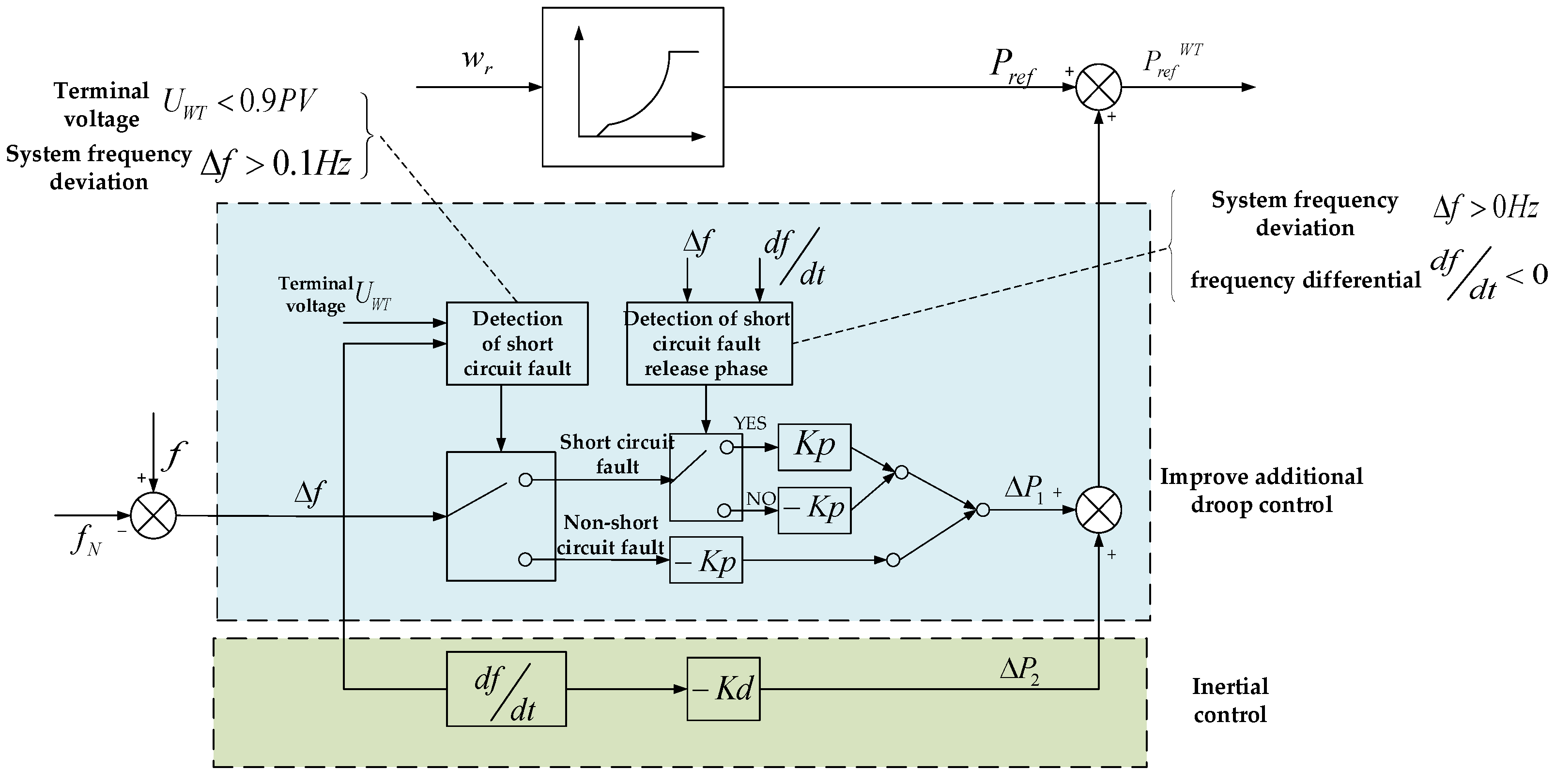
3. Improved Additional Frequency Control Strategy
According to the analysis in
Section 2.2, the instantaneous increase of active power demand causes the system frequency to drop dramatically after the short-circuit fault is removed. At this time, if the advantages of fast response of speed regulation of DFIGs can be brought into play, the rotating speed of DFIGs can be regulated in time to release kinetic energy. This can supplement the active power shortage of the system, and alleviate the frequency regulation pressure of synchronous generators. In order to reduce the rotating speed of DFIGs, the reference value of active power on the rotor side should be increased firstly, so that the output electromagnetic power of WTs is greater than the captured mechanical power.
As can be seen from
Figure 2, after the short-circuit fault is removed, the frequency begins to decrease, and the frequency deviation starts to decrease from the positive maximum value. At this time, the droop control which plays a dominant role is still negative, so that the output electromagnetic power is still lower than the captured mechanical power. The rotor of WTs is in the acceleration trend, which not only hinders the rapid release of kinetic energy, but also enhance the rapid drop of the system frequency.
Based on the analysis of inertia damping characteristics of conventional additional frequency control strategy for DFIGs under the condition of short-circuit fault exists in
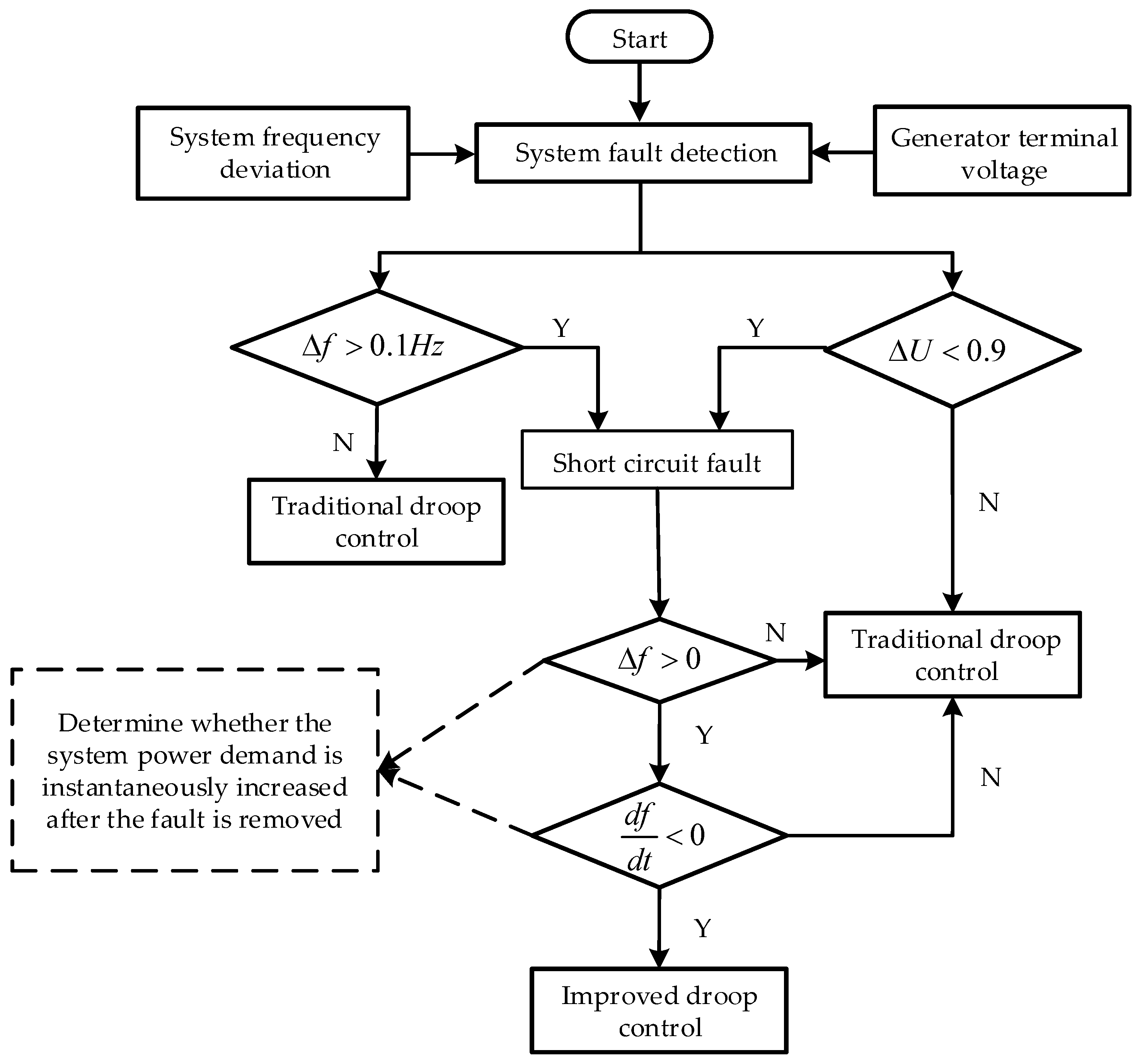
Section 2.2, this section proposes an improved additional frequency control strategy to overcome the limitations. The strategy modifies the droop control coefficient according to the frequency variation during the occurrence, development and removal of a short-circuit fault. The DFIGs have effective inertia damping characteristics throughout the whole process, so that the output active power will be adjusted in time with the frequency fluctuation. The implementation method of the improved additional frequency control strategy is shown in
Figure 3, and the specific implementation process is shown in
Figure 4.
When the frequency fluctuates due to a short-circuit fault, the WTs adopt the improved additional frequency control strategy shown in
Figure 3. The event that can cause the increase of system frequency are mainly load reduction or a short-circuit fault. Load reduction will cause a short-term increase in terminal voltage, while a short-circuit fault will cause a large drop in terminal voltage. In order to distinguish the two kinds of events, the variation of terminal voltage and the system frequency are introduced to judge whether a short-circuit fault occurs. When the terminal voltage amplitude is lower than 0.9 pu and the system frequency is higher than 50.1 Hz, the short-circuit fault of the system occurs. After the short-circuit fault is removed, the frequency starts to decrease and the frequency is still higher than the rated value, the value of additional active power produced by droop control remains unchanged when the symbol changes. Not until the frequency is below the rated value that the WTs are restored to the conventional additional frequency control. The detailed adjustment process can be seen in
Figure 4.
4. Results
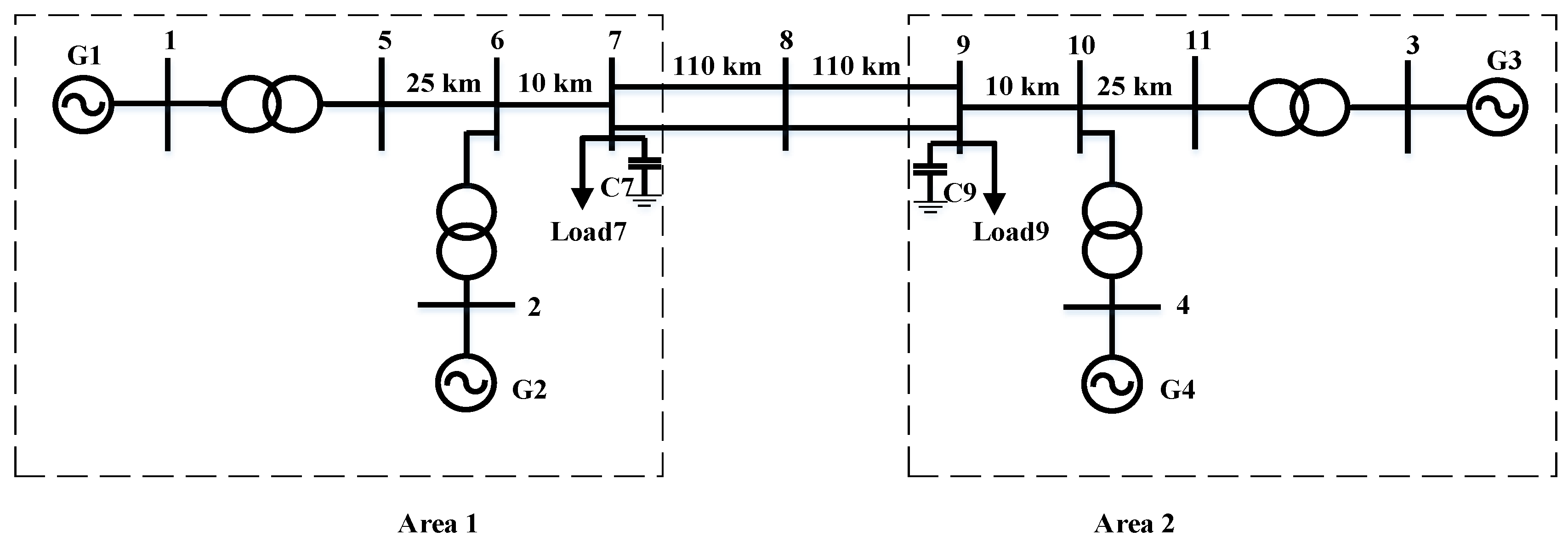
In this paper, a simulation model of four-machine two-area system including DFIGs is built in MATLAB/Simulink. The four-machine two-area test system of Kundur has been used to investigate the impact of the DFIGs on the power oscillation damping of the power system [
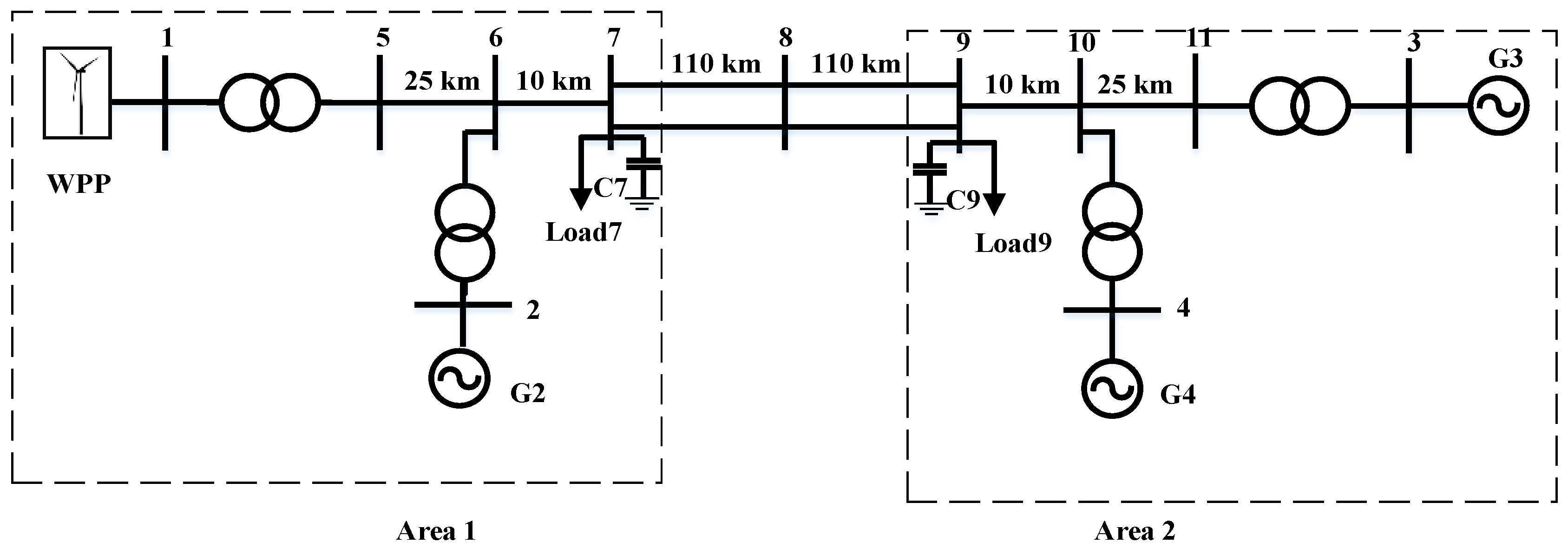
33]. This system is specifically used to study low frequency electromechanical oscillation modes in the interconnected power system. The single line diagram of the two-area test system is shown in
Figure 5. The two-area system is linked together by 230 kV lines of 220 km length. Each area has two round-rotor synchronous generators each with 20 KV/900 MVA rated power. All conventional synchronous generators are steam turbine driven, round-rotor synchronous generators provided with governor and excitation control. The synchronous generators are identical. The loads are modeled as constant impedances.
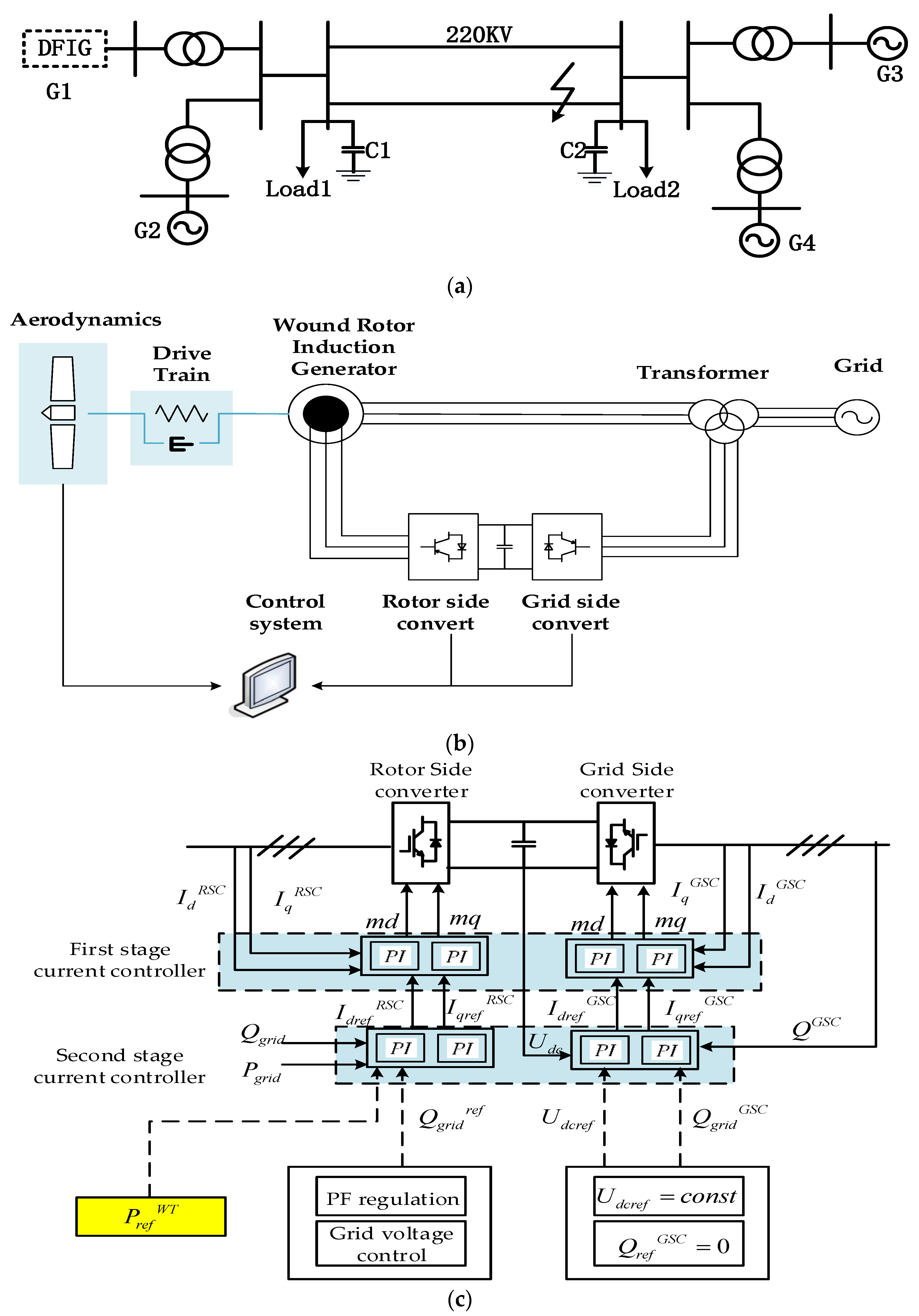
In order to examine the impact of DFIG-WPP on inertial damping characteristics of the power system, the synchronous generator G1 is replaced by the DFIG-based WPP as shown in
Figure 6.
To simplify the analysis, the above model is simplified as
Figure 7a, G1 is a doubly-fed wind farm with 300 doubly-fed wind generators. G2~G4 are power plants with governor and excitation regulator. The load L1 and L2 are constant active load respectively, C1 and C2 are reactive power compensation devices and the three-phase short-circuit fault occurs on the single circuit.
The typical DFIG configuration is considered, as illustrated in
Figure 7b. Its model includes the main electrical components, the mechanical and aerodynamic subsystems, and the controllers. In the converter control system, shown in
Figure 7c, the rotor-side converter (RSC) controls the active and reactive power delivered to the grid, while the grid-side converter (GSC) regulates the dc-bus voltage, operating at unity power factor.
The controller structure is based on cascaded loops: a fast inner current controller regulates current to the reference values, specified by external power control loops. The control scheme are presented based on the phasor model of the DFIGs system. In this section, an outline of the models used is only presented for the sake of completeness. Details are provided in [
34]. The load flow data is shown in
Table 1 and the main component parameters are reported in
Table 2.
At 50 seconds, a three-phase short-circuit fault occurs in one circuit of 220 kV high voltage transmission line. After the fault continues 0.15 s, the system is restored to the normal operation. In the additional frequency control, the virtual inertial control coefficient is 10.08 and the droop control coefficient is 1/0.03.
Under the three modes of no additional frequency control, conventional additional frequency control and improved additional frequency control proposed in this paper, the terminal voltage of DFIGs, the grid-connected point current, the voltage of the converter on DC side, the transmission frequency, the active power provided by WTs and the rotor speed of DFIGs are shown in
Figure 8.
4.1. Analysis of System Frequency Change
According to the comparative analysis of frequency variation under three different control strategies in
Figure 8d, it can be concluded that when the system adopts MPPT control without additional frequency control for DFIGs, the frequency fluctuation amplitude is the largest. The maximum frequency increased to 50.32 Hz. After the fault is removed, the frequency decreases to 49.50 Hz. By contrast, the maximum frequency offset is reduced to a certain extent by using conventional frequency control in addition. The maximum frequency amplitude is reduced from 50.32 Hz to 50.26 Hz during the period of a fault, and the maximum frequency deviation is reduced by 18.7% during the period of frequency rise. After the fault removal, the minimum amplitude of frequency is improved from 49.50 Hz to 49.68 Hz. The maximum frequency deviation decreased by 36% in the period of frequency drop. The DFIGs play an obvious role of inertia support in the process of frequency fluctuation. After adopting the improved additional frequency control, the DFIGs can adjust the rotational speed in time. This can release the stored kinetic energy in the rotor after the fault is removed and resumed normal operation, and the output active power increases, which effectively reduces the frequency offset. The minimum amplitude is 49.76 Hz during frequency decline, which is 25% higher than that of conventional additional frequency control. Compared with the former two methods, we can see that this method significantly weakens the trend of frequency oscillation and improves the stability of the system in the later period of frequency regulation.
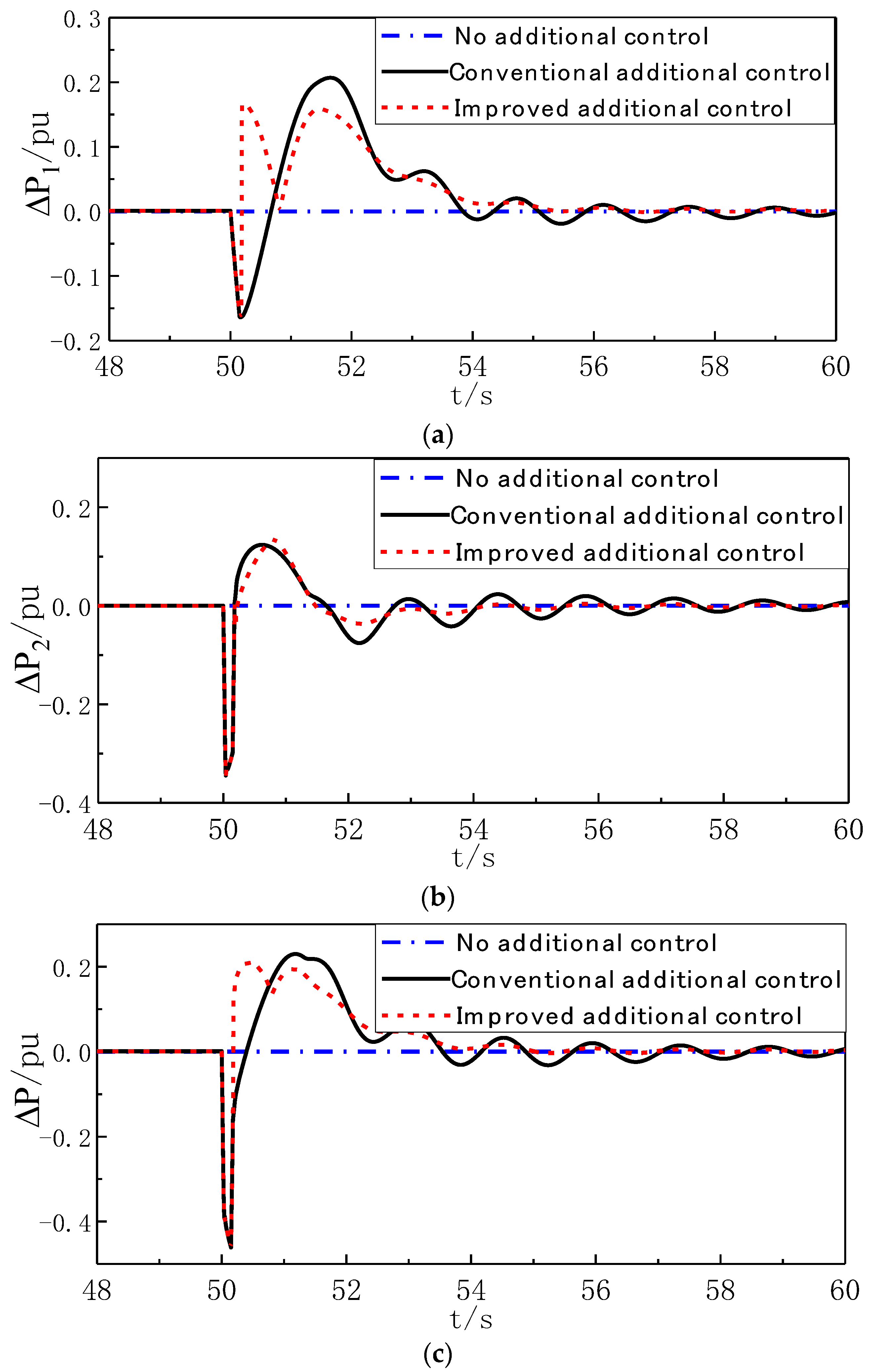
4.2. Analysis of additional power variation
Figure 9 shows the variation of the additional power of DFIGs under the three control modes.
As shown in
Figure 9, the additional power is 0 without additional frequency control. In the case of conventional additional frequency control, the analysis of additional power changes is detailed in
Section 2.1. In the case of improved additional frequency control, after the short-circuit fault is removed, the frequency deviation begins to fall from the maximum positive value to zero. During this period, the additional power △P
1 produced by droop control is changed from positive to negative. The total additional power is increased from −0.1 pu of the conventional additional to 0.2 pu at the time of the fault removal. The increase of active power reference value enables the DFIGs to adjust the kinetic energy and the rotational speed timely and increase the output active power.
4.3. Analysis of Output Active Power of DFIGs
By comparing and analyzing the change of output active power of DFIGs in the process of frequency mutation in
Figure 8e, it can be seen that when the DFIGs operate in MPPT mode without additional frequency control, the output active power fluctuates in a small range near 0.38 pu, and almost has no response to system frequency. With conventional additional frequency control, the output power of DFIGs can rapidly follow the change of active power reference value through additional power signal after a short-circuit fault occurs, and instantaneously reduces to 0.13 pu. The reduction of output power leads to the increase of speed, which makes the WTs deviate from the MPPT mode and overspeed. The reserve of rotor kinetic energy is increased. After the fault is removed, the additional power signal makes the output power instantly rise to 0.28 pu, which is still lower than the mechanical power. It is unable to meet the instantaneous active power demand of the system. Then the output active power gradually increases until the electromagnetic power is greater than the captured mechanical power. The speed begins to drop and the power is released. When the additional frequency control is improved, after the fault is removed, the additional power signal makes the output power rise to 0.43 pu instantaneously, which is larger than the captured mechanical power. The rotational speed of the WTs decreases and releases kinetic energy to replenish the active power in time.
4.4. Analysis of Speed Variation of DFIGs
Through the change of rotational speed of DFIGs in
Figure 8f, we can see that when DFIGs have no additional frequency control, in order to maintain the optimal tip speed ratio, the rotational speed only adjusts with the change of wind speed, and cannot respond to the frequency change of the system. The rotational speed is always maintained at 1pu. Under the condition of conventional additional frequency control, the WTs can adjust the rotational speed of the system to response to the frequency change of the system. The rotational speed of DFIGs increases with the increase of the system frequency and absorbs excess active power in the period of a fault. However, after the fault is removed and returns to normal operation, the frequency shows a downward trend, but still higher than the rated value. Droop control plays a leading role, and the additional power is related to frequency deviation. In a short period after the fault is removed, the value is opposite to the frequency change rate. The rotational speed of the WTs still has an upward trend, which is not conducive to the rapid stability of the system frequency. Aiming at the problems of conventional additional frequency control, improving additional frequency control can make the rotational speed of WTs adjust rapidly according to the change trend of system frequency. From the figure, it can be seen that the improved additional frequency control can reduce the rotational speed in time after the frequency starts to decrease, and release kinetic energy to provide effective support for the system.
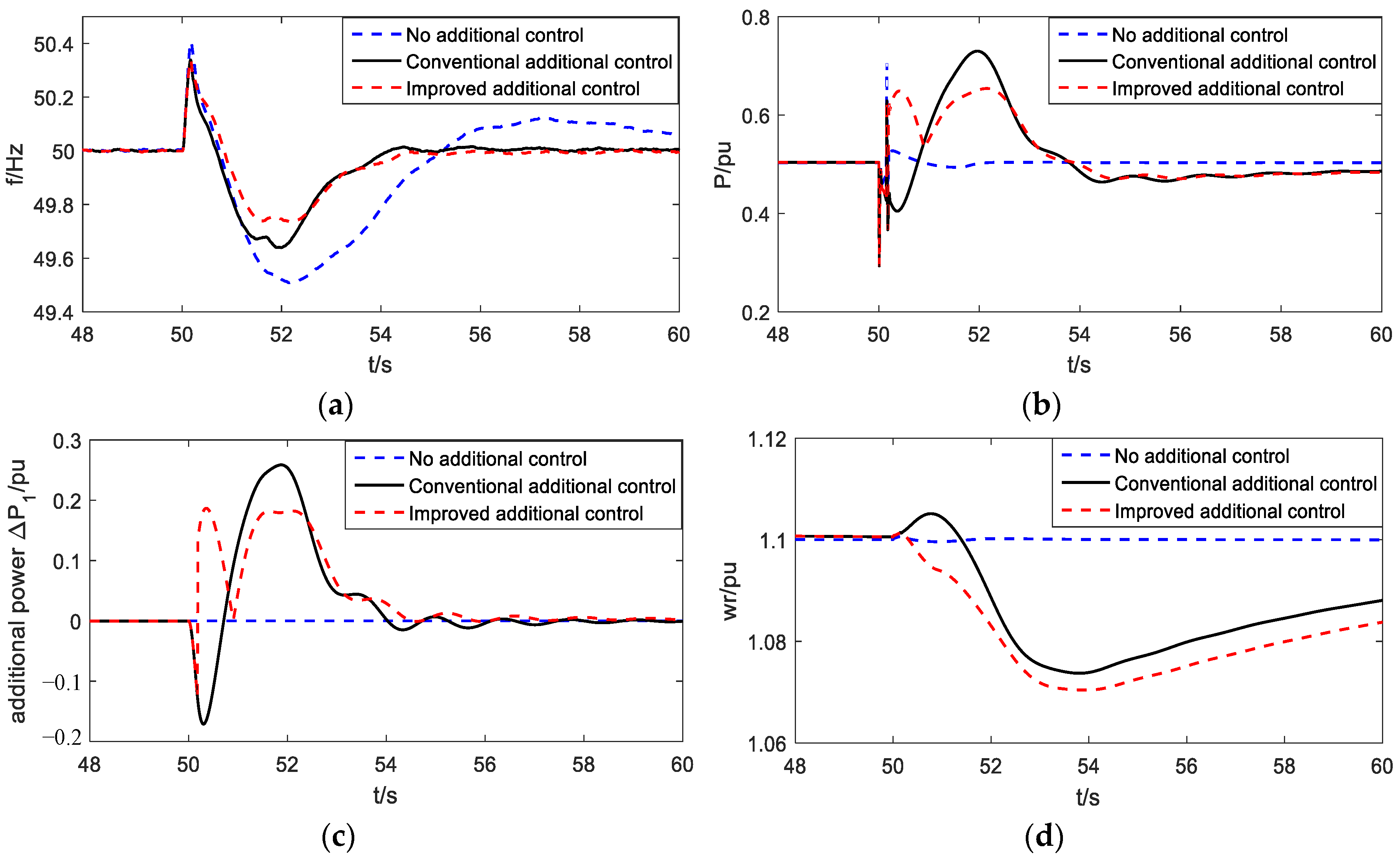
4.5. Analysis at Different Wind Speeds
In order to verify the effectiveness of the improved strategy, this section performs simulation analysis under different wind speeds, which is to prove that the improved strategy can effectively improve the frequency regulation of the system under different operating points.
Figure 10 shows the variation of the system frequency, the output active power of DFIGs, the additional power of DFIGs and the rotational speed of DFIGs under three different control modes in the wind speed of 8 m/s. and
Figure 11 shows the variation in the wind speed of 11 m/s.
It can be seen from
Figure 10 and
Figure 11 that the variation trends of each variable are similar under different wind speed conditions. After adopting the improved additional frequency control, the DFIGs can adjust the rotational speed in time to release the stored kinetic energy in the rotor after the fault is removed and resumed normal operation, and the output active power increases, which effectively reduces the frequency offset. Comparing with the former two methods, we can see that this method significantly weakens the trend of frequency oscillation and improves the stability of the system in the later period of frequency regulation. Therefore the improved control method is suitable for different operating conditions.
5. Conclusions
The large-scale grid connection of DFIGs has a significant influence on the stability of the power system. The additional frequency control strategy of DFIGs has a vital effect on the frequency fluctuation caused by the sudden change of load, but the control has some limitations on the frequency fluctuation caused by the short-circuit fault. In this paper, the variation law of the system frequency during the whole process from the occurrence to the removal of the short-circuit fault has been deeply studied, and the parameters in the additional frequency control of the DFIGs have been modified, so that the output power of the DFIGs can be quickly adjusted with the change of the system frequency. And the transient stability of the system is improved. The experimental results have shown that after adopting the improved additional frequency control, the DFIGs release the stored kinetic energy after the fault removal and resumes normal operation, which effectively reduces the frequency offset, and the improved control method is suitable for different operating conditions, which has a highly applicability to the frequency regulation of wind power grid-connected systems in the future.


