Article

Enhancement of a R-410A Reclamation Process Using Various Heat-Pump-Assisted Distillation Configurations

1
School of Chemical Engineering, Yeungnam University, Gyeongsan 712-749, Korea
2
OunR2tech Co., Ltd, Pohang 37553, Korea
*
Author to whom correspondence should be addressed.
These two authors contributed equally to this work.
Energies 2019, 12(19), 3776; https://doi.org/10.3390/en12193776
Submission received: 15 September 2019 / Revised: 25 September 2019 / Accepted: 2 October 2019 / Published: 4 October 2019
(This article belongs to the Special Issue Refrigeration Systems and Applications 2019)

Abstract

:
Distillation for R-410A reclamation from a waste refrigerant is an energy-intensive process. Thus, various heat pump configurations were proposed to enhance the energy efficiency of existing conventional distillation columns for separating R-410A and R-22. One new heat pump configuration combining a vapor compression (VC) heat pump with cold water and hot water cycles was suggested for easy operation and control. Both advantages and disadvantages of each heat pump configuration were also evaluated. The results showed that the mechanical vapor recompression heat pump with top vapor superheating saved up to 29.5%, 100.0%, and 10.5% of the energy required in the condenser duty, reboiler duty, and operating cost, respectively, compared to a classical heat pump system, and 85.2%, 100.0%, and 60.8%, respectively, compared to the existing conventional column. In addition, this work demonstrated that the operating pressure of a VC heat pump could be lower than that of the existing distillation column, allowing for an increase in capacity of up to 20%. In addition, replacing the throttle valve with a hydraulic turbine showed isentropic expansion can decrease the operating cost by up to 20.9% as compared to the new heat pump configuration without a hydraulic turbine. Furthermore, the reduction in carbon dioxide emission was investigated to assess the environmental impact of all proposed sequences.

Graphical Abstract

1. Introduction

Traditional refrigerants including hydrochlorofluorocarbons (HCFCs) (e.g., chlorodifluoromethane CHClF2 (R-22)) and chlorofluorocarbons (CFCs) can cause global warming and ozone depletion owing to their poor stability in the atmosphere. Therefore, they are being replaced by other environmentally friendly products, such as hydrofluorocarbons (HFCs) (e.g., R-410A) [1,2,3]. R-410A, which is an azeotropic mixture of difluoromethane (R-32) and pentafluoroethane (R-125), has been developed as a long-term replacement for R-22 [4]. Although they provide an effective alternative to HCFCs and CFCs, they are still greenhouse gases with long atmospheric lifetimes.
Refrigerant reclamation is defined as the processing of used refrigerant gases so that they can meet specifications for re-use. Reclamation services were designed with the objective of reducing the environmental impact of used refrigerants, allowing for the recycling of existing refrigerants, thereby avoiding the need to manufacture new refrigerant molecules [5]. One of the main challenges in refrigerant reclamation is to separate and purify refrigerant mixtures because they usually form azeotropic mixtures or close-boiling mixtures [6]. Therefore, in view of the current restrictions associated with refrigerants, developing new, effective, and efficient methods to separate and purify individual components from an azeotropic mixture is crucial.
A few techniques have recently been developed to separate R-410A and R-22. Wanigarathna et al. proposed an adsorption process for the separation of mixtures of R-32, R-22, and R-125 using 4A molecular sieve zeolite [7]. The expensive equipment (material) used in adsorption due to the need for a considerable amount of stationary phase material is also significant. The distillation process, which is the most common process employed in the chemical and petrochemical industries, is used for this separation in OunR2tech company in Korea. However, distillation for separating R-410A and R-22 is an energy-intensive process. There is a need to enhance the energy efficiency of this process and to decrease direct emissions of greenhouse gases, which have a considerable impact on climate change.
Distillation is a well-developed, thermal-driven separation process and is extensively used in the chemical industry; however, it consumes a massive amount of fossil fuel as the heat source. There are several ways to improve the performance of distillation as this will lead to a reduction in the consumption of fossil fuel, thereby leading to a significant carbon dioxide (CO2) emissions reduction. One of the most attractive solutions is using cleaner electricity generated from sustainable energy sources, such as wind power and solar cells. Heat pump (HP) technology, which allows for the use of the waste heat released at the condenser for supplying energy to the reboiler, is a cost-effective approach to reducing the energy requirement of the distillation column [8,9,10,11]. This technology can be beneficial in the case of the small temperature difference between the overhead and bottom of the column and the high heat load. To reduce the energy requirement of the distillation columns, several HP concepts have been developed. Among them, the mechanical vapor recompression (MVR) heat pump and vapor compression (VC) heat pump are the most popular configurations. As the heat is exchanged only once in an MVR, along with a smaller condenser and the lower temperature lift, is advantageous over a VC, this results in a higher thermodynamic efficiency [12].
Considering all the above-mentioned issues, in this study, various HP configurations were proposed for enhancing the energy efficiency of the existing conventional distillation for R-410A reclamation from a waste refrigerant. Top vapor superheating was proposed for improving the performance of the HP configuration, as well as for protecting the compressor from liquid leakage. One new HP configuration combining the VC with cold water and hot water cycles was suggested for easy operation and control. Furthermore, hydraulic turbines were evaluated to enhance the performance of the new HP configuration. The reduction in CO2 emissions was also determined as part of the evaluation of all proposed sequences.

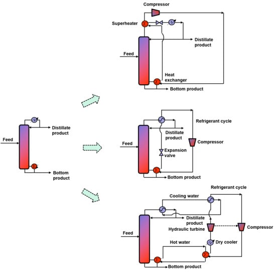
2. Proposed Configurations for Improving Reclamation Process

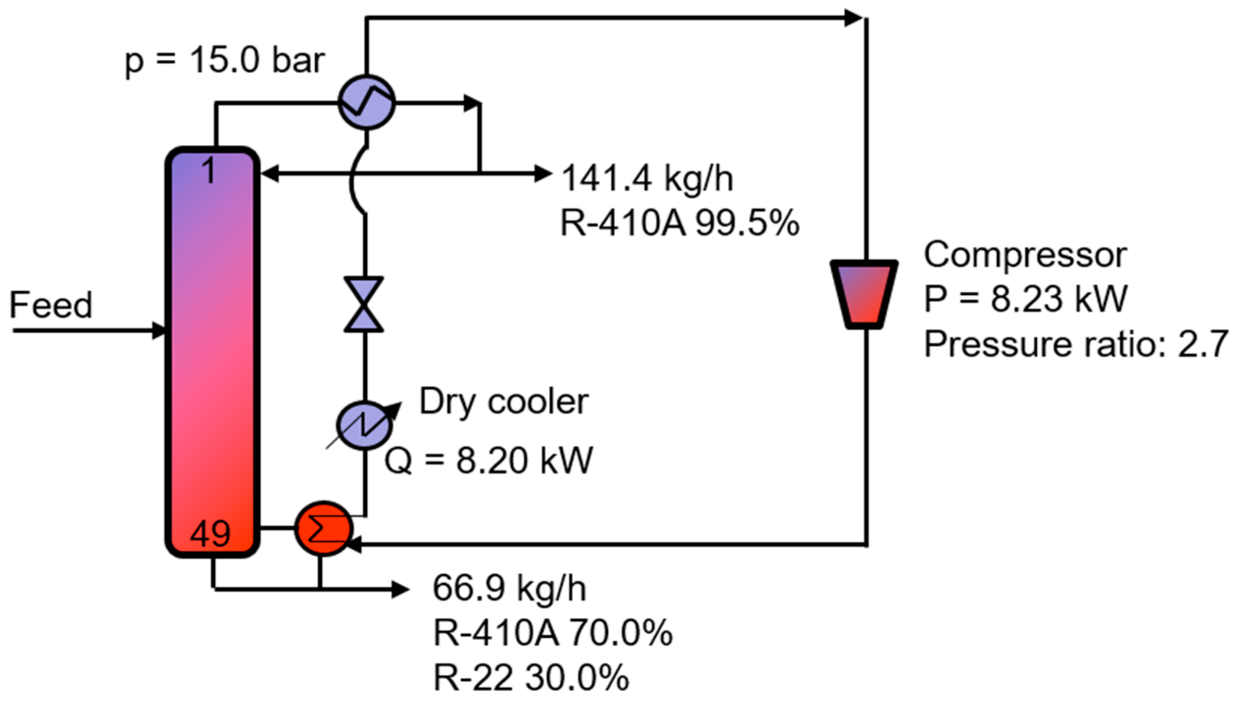
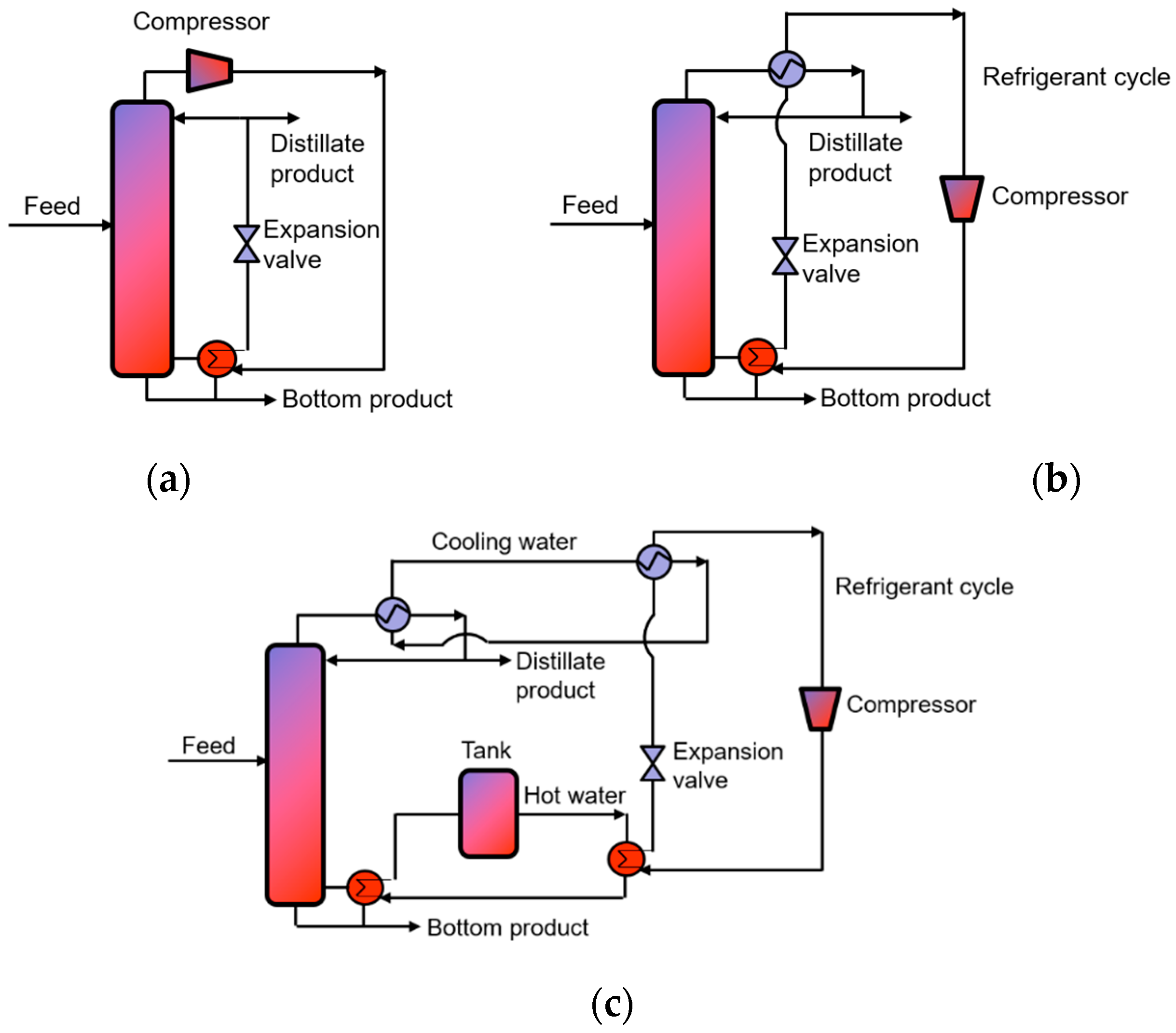
2.1. Mechanical Vapor Recompression

MVR (Figure 1a) can be applied in many industrial processes, such as crystallization, evaporation, stripping, drying, and distillation [13,14,15]. In such a system, the overhead vapor is fed directly to the compressor and compressed to a level that can transfer the heat to the reboiler, leading to a significant reduction in the energy consumption of both the condenser and reboiler [16,17,18,19,20,21]. An HP is desired if the coefficient of performance (COP) or the ratio of the amount of heat delivered to the reboiler (Q) and the external work (W) is more than 10, while further evaluation is necessary if this value is between 5 and 10 and should not be considered when the Q/W ratio is lower than 5 [21,22].

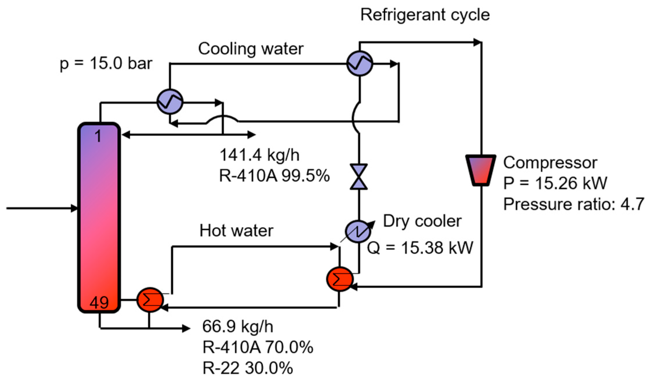
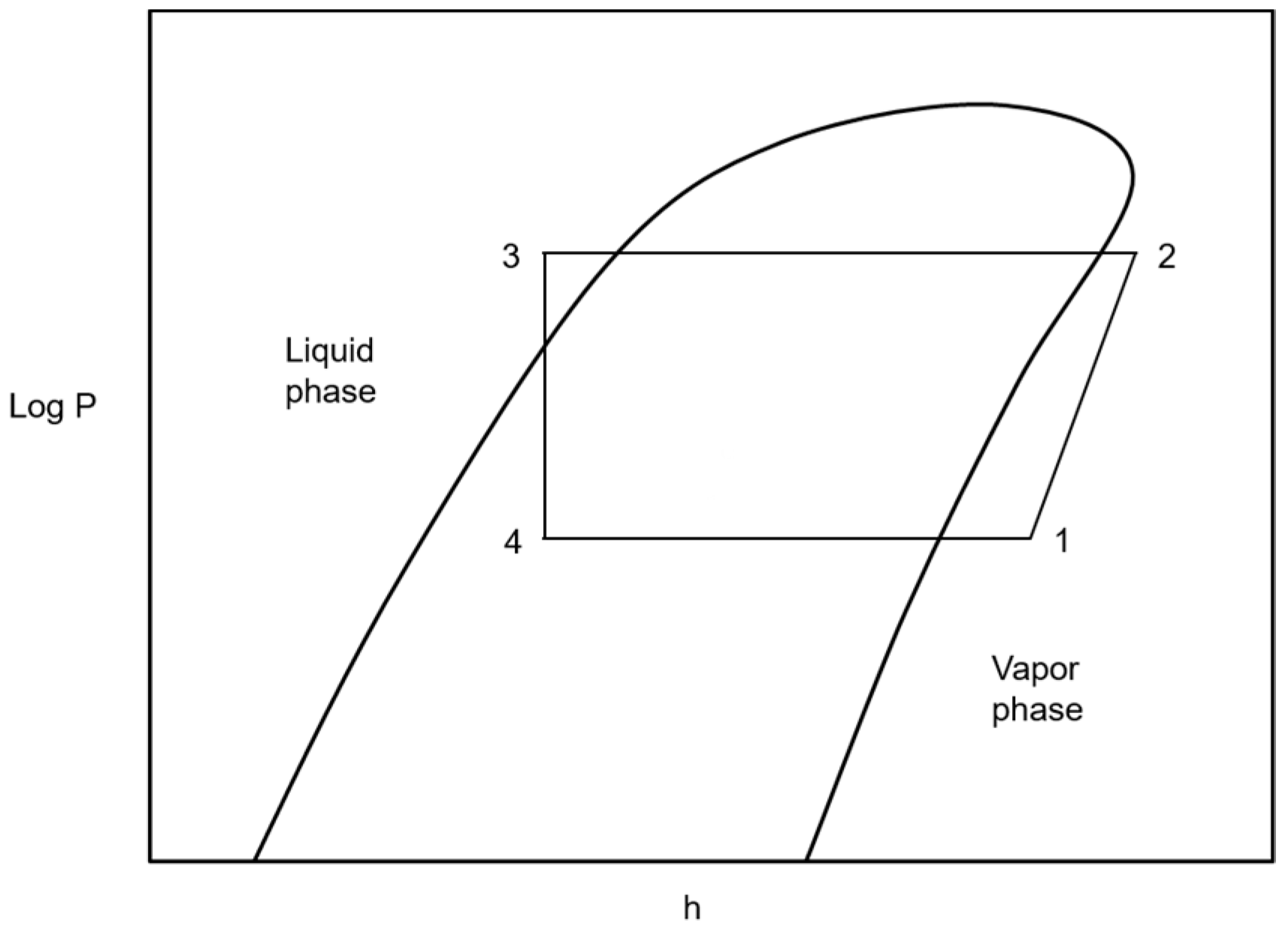
2.2. Vapor Compression Heat Pump

VCs are the most common type of HPs with a limited current maximum temperature of 120 °C [15]. In VC (Figure 1b), a specific working fluid is used as a heat transfer medium. The main characteristic of VC is the phase change of this fluid. In particular, the working fluid obtains the waste heat from the low-temperature overhead vapor stream to convert the working fluid to vapor before being compressed by a compressor to increase its pressure and temperature. The compressed fluid then supplies energy to the bottom products to boil the column up and be changed to a liquid phase [13]. In the next stage, the fluid enters an expansion valve to reduce its pressure and temperature before continuing another cycle. To achieve a good performance, the most important parameter is the choice of suitable working fluid.

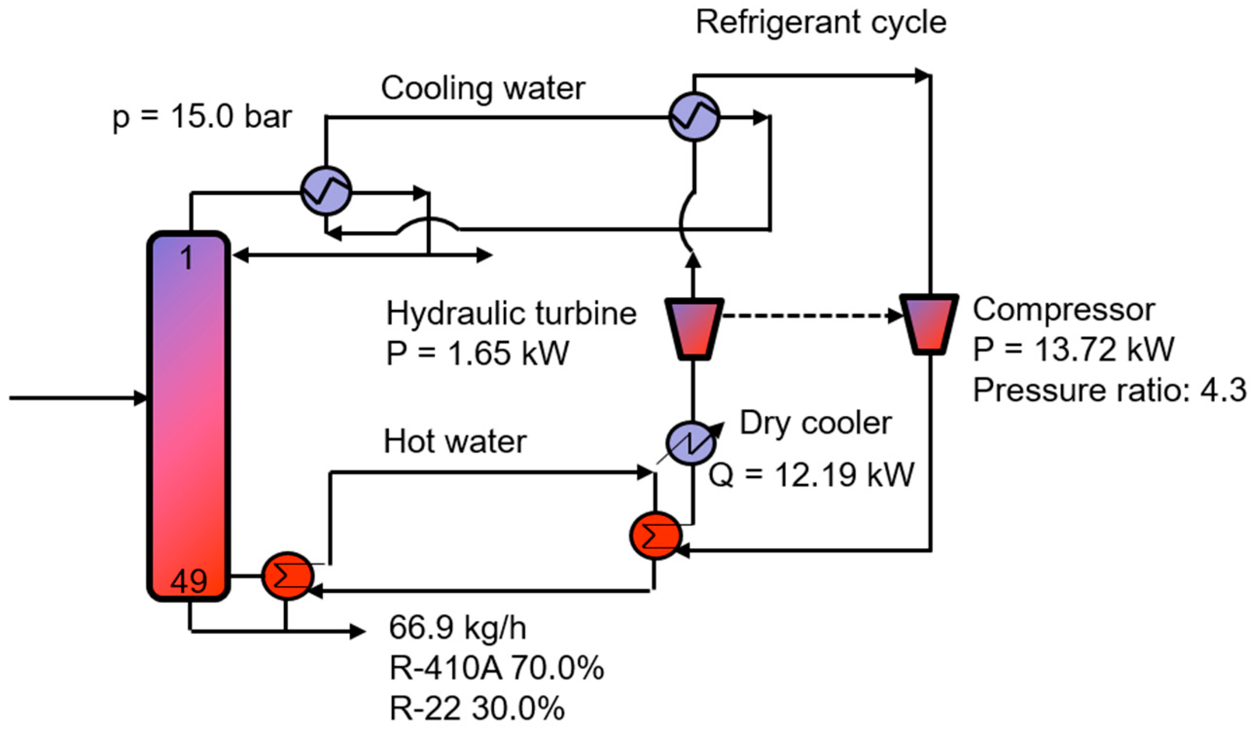
2.3. New Configuration

In VC heat pumps, a buffer tank containing a certain amount of refrigerant is needed. During low-load conditions, the extra volume of refrigerant would absorb any of the extra heat generated by the HP. However, the refrigerant is quite expensive. Thus, in the cases where the difference between the top and bottom temperatures is less, a new configuration containing a cheap water buffer tank can be considered. Figure 1c shows the process flow diagram of the proposed new configuration. This can be considered as the modified VC configuration with one hot water cycle and one cold water cycle.
In this new configuration, the operating conditions of the HP cycle are modified such that the temperature of the refrigerant is lower than that of cooling water. After obtaining the waste heat from the overhead vapor, the cooling water transfers the heat to the refrigerant in a heat exchanger. This heat totally generates refrigerant vapor and superheats it. Afterward, the superheated refrigerant is introduced into a compressor to convert it to a higher temperature and pressure. The high-temperature refrigerant is then cooled down to its dew point, condensed, and cooled below its boiling point by releasing thermal energy to provide the heat to the hot water used to boil the column up. Before completing the cycle, this refrigerant is passed through a valve to reduce its pressure, temperature, and bubble point temperature.
Creating temperature differences between the cooling water and overhead vapor, the cooling water and the refrigerant, the refrigerant and the hot water, and the hot water and the bottom product is necessary. Therefore, supplying a minimum temperature approach in the heat exchangers required a larger compression ratio value of the compressor. Thus, the energy and economic performance of our proposed configuration is usually lower than that of VC and MVR. Nevertheless, as this configuration only has a water buffer tank, it is cheaper than the system containing the expensive refrigerant buffer tank. Furthermore, the performances of this system can be higher if cheaper electricity is produced in some companies or countries and cleaner electricity obtained from sustainable energy sources are used to drive the compressor of the HP system. Besides, implementation, operation, and control become simple.

3. Results and Discussion

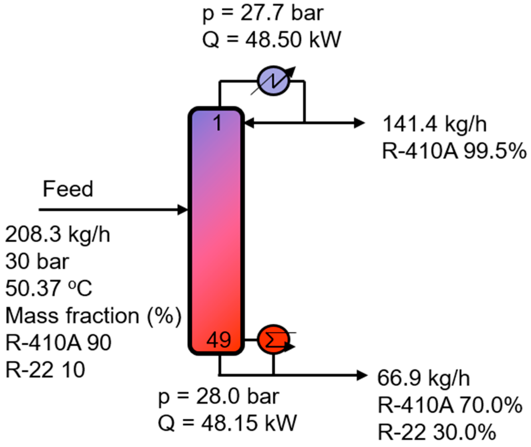
3.1. Existing Conventional Distillation Column
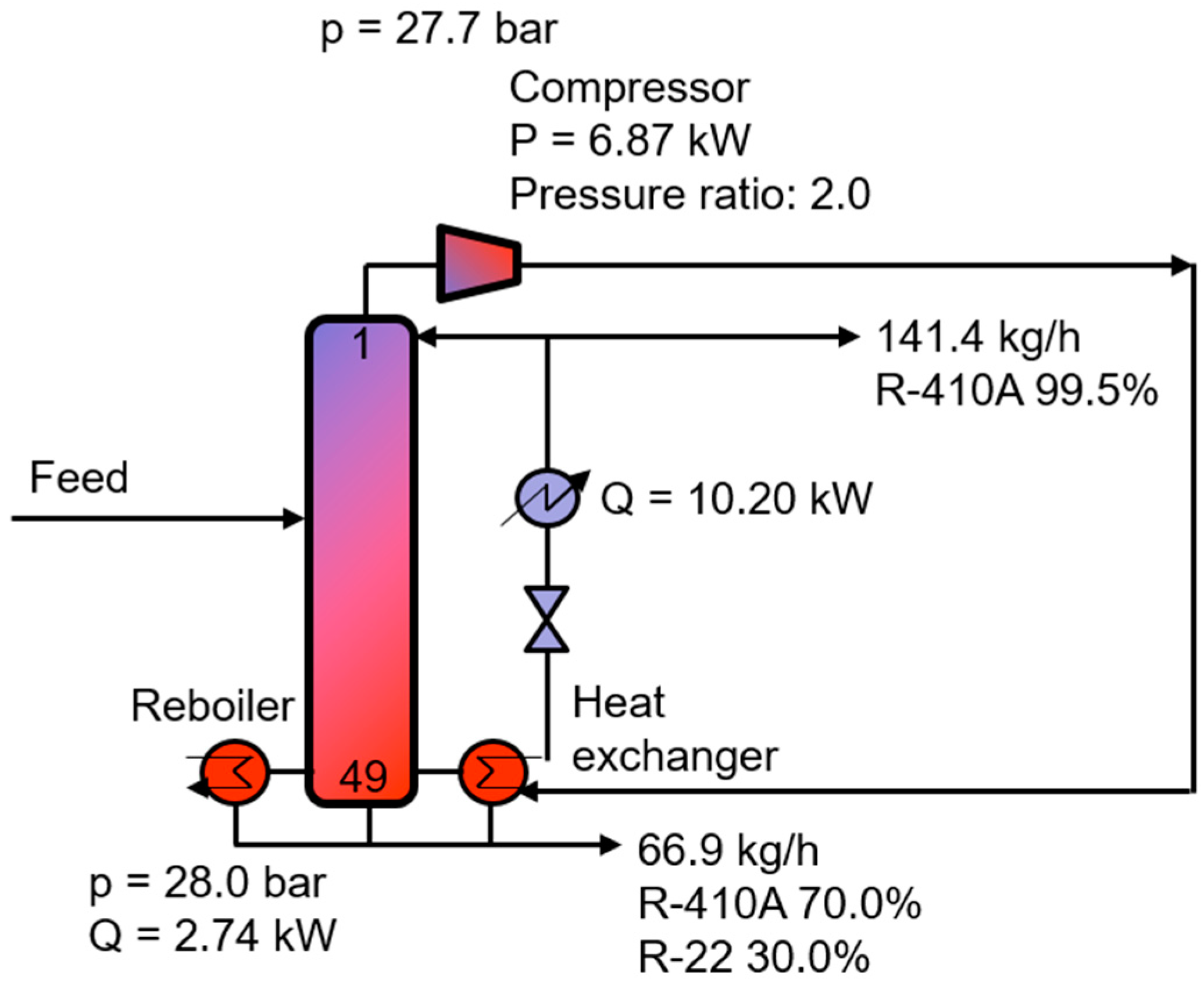
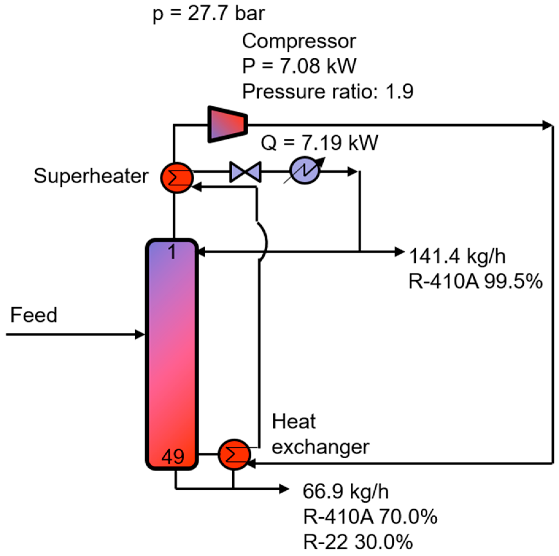
The existing conventional distillation column operated at 27.7 bar possesses 49 theoretical stages. The flowchart of the existing distillation column for the R-410A reclamation from a waste refrigerant is presented in Figure 2. The light product R-410A (purity: 99.5%) was obtained from the top of the column. Aspen HYSYS V10 (Aspen Technology, Inc., Bedford, MA, United States) was employed to simulate all configurations in this study. The REFPROP property method provided thermodynamic and transport properties of industrially important fluids with an emphasis on refrigerants [23]. Thus, REFPROP was selected as the property package for all simulations in this study. The reboiler duty of the existing distillation column was 48.15 kW (shown in Table 1).

3.2. MVR Heat Pump

In the existing column, the COP value of 8.5 revealed that the heat released in the condenser can be utilized to supply the reboiler through an MVR system. The flowchart for the MVR-assisted distillation column is shown in Figure 3. In this configuration, an extra reboiler was utilized because the amount of energy transferred was insufficient. Compared to the existing conventional distillation column, the use of an MVR heat pump could improve the reboiler duty and operating costs by 94.3% and 56.2%, respectively, as shown in Table 2. Note that the costs of low-pressure steam, cooling water, and electricity were 6.08 $/GJ, 0.35 $/GJ, and 16.80 $/GJ, respectively, which were used for the calculation of the total operating cost [24].
In some cases, there is partial condensation of saturated vapor in the compressor, causing a liquid break. To avoid this problem, the top vapor was modified to pass through the compressor after it was superheated by the remaining heat in the exchanger outlet stream in a superheater (shown in Figure 4) [14,25]. In this configuration, both latent heat and sensible heat were used to supply the heat to the reboiler and superheat the top vapor stream. Because of preheating of the top product, a lower remaining reboiler duty and condenser duty were required. Specifically, the remaining reboiler duty was decreased from 2.84 kW to 0 kW, i.e., this column was driven by self-heat recuperation. In addition, the remaining condenser duty was reduced from 10.20 kW to 7.19 kW, i.e., more savings were achieved by adding a heat exchange stage to heat the top vapor stream of the column before passing through the compressor. Furthermore, the pressure ratio was reduced slightly from 2.0 to 1.9.
This modification can induce savings of 29.5% and 100.0% in terms of condenser duty and reboiler duty, respectively, as compared to the MVR-assisted distillation without superheating. Moreover, using this sequence can save 60.8% in terms of the operating cost compared to the existing distillation column. These savings can be higher if cleaner electricity obtained from sustainable energy sources, such as wind or solar power, is used to drive the compressor of the HP system.

3.3. VC Heat Pump

The selection of an appropriate working fluid is an important parameter in the design of a VC heat pump configuration. In this work, to select the working fluid, the following criteria were considered [25]:
  • The bubble point of the working fluid at 1.01 bar must be less than the temperature of the top vapor by at least 10 °C.
  • The dew point of the working fluid at higher pressure should be higher than the reboiler temperature by at least 10 °C.
Under the operating conditions of the distillation column, R-22 is a good working fluid. Nevertheless, R-407C, which is a blend of R-32, R-125, and 1,1,1,2-tetrafluoroethane (R-134A), is a similar refrigerant to R-22 in terms of working pressure, capacity, and energy efficiency for above-zero and mid-range evaporation temperatures [26]. R-407C has emerged as the popular choice for supermarket refrigeration equipment because of its good performance match to R-22 and its lower global warming potential than other alternatives [27]. Thus, R-407C was selected as the fluid for the refrigeration cycle.
The adiabatic efficiency of the compressor was assumed to be 75% and the minimum temperature approach in the heat exchanger was assumed to be 10 °C. Note that the superheating level was 3 °C and the subcooling level was 2 °C. The parameters affecting the overall utility energy consumption were the pressure of the compressor inlet and outlet streams and the flow rate of the working fluid [28]. They were adjusted to satisfy the minimum temperature approach of 10 °C in each heat exchanger of the system and superheating level of 3 °C. Because the heat capacity of the HP system exceeded the reboiler duty, one dry cooler was installed to release the extra heat and achieve a subcooling level of 2 °C.
The flowchart of the VC-assisted distillation column is shown in Figure 5. Interestingly, because the VC heat pump configuration did not have a condenser using cooling water, the column could be operated at a lower operating pressure. As indicated in Table 2, the VC-assisted distillation column can save more reboiler duty and condenser duty than an MVR-assisted distillation configuration. However, heat was exchanged twice, and the temperature increase in the VC heat pump was 10 °C higher than that of the MVR system. This induced a higher compression duty, causing lower operating cost savings (54.5%) compared to 56.2% when using MVR.
Note that operating at a lower pressure reduced the energy required to drive the column of the VC heat-pump-assisted distillation, which facilitated an increase in capacity. In particular, the capacity of this configuration could be increased by up to 20% compared to the existing conventional distillation and MVR heat pump system. In addition, the total annual CO2 emissions calculated using Gadalla’s modular method [29] decreased by up to 50.7% compared to the existing conventional distillation column.

3.4. New Heat Pump Configuration

Another configuration including a refrigerant cycle, a hot water cycle, and a cold water cycle was also considered to improve the existing conventional distillation column (shown in Figure 6). Note that the cooling water temperature was 7 °C, whereas hot water temperature was 45 °C. The thermodynamic cycle of the new configuration is shown in Figure 7. The superheated fluid (1: T = 1.1 °C, P = 4.3 bar) entered the compressor to increase its pressure. Then, the compressed working fluid (2: T = 79.5 °C, P = 20.3 bar) was first cooled down to its dew point, condensed, and cooled below its boiling point (3: T = 44.2 °C, P = 20.3 bar). Next, the pressure and temperature of this working fluid were decreased using a Joule–Thompson (JT) throttling valve (4: T = −6.1 °C, P = 4.3 bar). Finally, the vapor–liquid mixture was totally evaporated and superheated in the heat exchanger with cooling water. Because compressor suction pressure Pin (4.3 bar) was higher than the atmospheric pressure, it could be reduced easily.
Compared to VC, the high temperature difference between the low pressure and high pressure working fluids created a need for large compression ratios of the compressor. As a result, despite the high savings in terms of condenser duty (68.3%) and reboiler duty (100.0%), the operating cost savings were only 15.6% as compared to the existing conventional distillation column.
A JT throttling valve is the most widely used expansion device in refrigerant cycles because of its many practical advantages, such as simplicity, and low investment and maintenance costs [30]. However, from a thermodynamic point of view, it has an inherent limitation, which is a low expansion efficiency because an expansion process through the JT valve essentially consists of an isenthalpic process. On the other hand, in the case of a hydraulic turbine expansion (also known as a liquid expander)-based refrigeration cycle, the liquid portion of the working fluid will be higher than that employing the JT valve. Thus, the isentropic expansion will result in a higher cooling capacity per unit mass of mixed refrigerant with lower shaft work [30,31,32,33,34]. Recent technological advancements in cryogenic liquid expansion turbines have enabled the replacement of the JT expansion valve with a cryogenic power recovery turbine [30,31,35]. This was used to improve liquefied natural gas operations [30,36,37].
Thus, the hydraulic turbine was investigated to replace the JT valves and consequently improve the energy efficiency of the HP cycle (shown in Figure 8). As a result, the outlet of the JT valve had the same molar enthalpy as the inlet stream, whereas the outlet of hydraulic turbine had a higher molar enthalpy (7.790 × 10⁵ kJ/kg∙mol) than that of the inlet stream (7.785 × 10⁵ kJ/kg∙mol). Furthermore, the temperature and vapor portions of the working fluid in the outlet stream were lower than those using the JT valve. This resulted in a higher minimum temperature approach between the cold water and the working fluid, consequently increasing the cooling capacity per unit mass of working fluid and decreasing the compressor duty. In particular, the compressor duty was reduced from 15.26 kW to 13.72 kW. Additionally, 1.65 kW could be generated by using the hydraulic turbine, which could be used to drive the compressor. Thus, the hydraulic turbine not only increased the efficiency of the HP system by performing the isentropic throttling function ideally, but also recovered the work of expansion. Consequently, the operating cost savings could be up to 20.9% and 33.2% as compared to the new HP configuration without a hydraulic turbine and an existing distillation column, respectively.
Table 2 summarizes the results concerning the operating cost and CO2 emission performance comparisons between all heat pump arrangements studied in this work and the existing conventional column. The performances of these configurations can be higher if cheaper electricity is produced in the companies or countries in question and cleaner electricity is obtained from sustainable energy sources, such as wind or solar power, are used to drive the compressor of the HP system. To select the suitable configuration, the decision-maker should consider not only the energy performance and environmental impact, but also the operability of the system. The main purpose of this paper was to show the feasibility of the enhancement of the R-410A reclamation process using various heat-pump-assisted distillation configurations. We would like to save operability analysis and proposed control structure of these configurations for the next paper.

4. Conclusions

The purpose of this study was to propose different heat-pump-assisted distillation configurations for improving the energy efficiency of the R-410A reclamation process from a waste refrigerant. Top vapor superheating was proved to be a promising option for improving the performance of HP configurations, as well as protecting the compressor from the liquid break. This modification could induce savings of 29.5% and 100.0% in terms of condenser duty and reboiler duty, respectively, compared to MVR-assisted distillation without superheating. As a result, using this sequence could save 60.8% in terms of operating cost compared to the existing distillation column. These savings can be higher if cheaper electricity produced in some companies or countries and cleaner electricity obtained from sustainable energy sources, such as wind or solar power, are used to drive the compressor of the HP system. This study also demonstrated that the VC heat pump could be operated at a lower operating pressure than the existing distillation column and this could induce an increase in capacity of up to 20%. Furthermore, this work proposed an effective HP configuration that was easy to operate and control. The hydraulic turbine not only increased the efficiency of the HP system by performing the isentropic throttling function ideally, but could also recover the work of expansion. The results also indicated that the CO2 emission could be reduced significantly when enhancing the existing conventional distillation column using HP configurations.

Author Contributions

N.V.D.L. and T.H.H. conducted the main job of modeling and designing all configurations. D.Y.L. aided in designing the enhanced configuration. S.Y.P. and B.B.H. aided in the design of the new configuration. M.L. conceived the core concepts for the research and provided academic advice. All authors collaborated for the preparation, revisions, and general editing of this manuscript.

Funding

This work was supported by the Basic Science Research Program through the National Research Foundation of Korea (NRF) funded by the Ministry of Education (2018R1A2B6001566), and by Priority Research Centers Program through the National Research Foundation of Korea (NRF) funded by the Ministry of Education (2014R1A6A1031189), and the R&D Center for Reduction of Non-CO2 Greenhouse Gases (201700240008) funded by the Ministry of Environment as a “Global Top Environment R&D Program.”

Conflicts of Interest

The authors declare no conflict of interest.

References

  1. Summary of Refrigerant Reclamation Trends. Available online: https://www.epa.gov/section608/summary-refrigerant-reclamation (accessed on 11 August 2019).
  2. Available online: https://www.agas.co.uk/products-services/recovery-reclamation-disposal (accessed on 11 August 2019).
  3. Refrigerant reclaim solutions. Available online: http://www.linde-gas.com/en/images/Refrigerant%20Reclaim%20Solutions%20brochure_tcm17-108595.pdf (accessed on 11 August 2019).
  4. Refrigerant 410A. Available online: https://www.rses.org/assets/r410a/R-410A.PDF (accessed on 11 August 2019).
  5. Available online: https://www.boconline.co.uk/en/products-and-supply/refrigerant-gases/reclaim-recovery-and-waste-management/index.html (accessed on 11 August 2019).
  6. Gregorio, T. Apparatus and Process for the Separation and Purification of Ideal and Non-Ideal Refrigerant Mixtures. US8075742, 13 December 2011. [Google Scholar]
  7. Wanigarathna, D.J.A.; Gao, L.; Takanami, T.; Zhang, Q.; Liu, B. Adsorption separation of R-22, R-32 and R-125 fluorocarbons using 4A molecular sieve zeolite. Chem. Select 2016, 1, 3718–3722. [Google Scholar]
  8. Chew, J.M.; Reddy, C.C.S.; Rangaiah, G.P. Improving energy efficiency of dividing-wall columns using heat pumps, organic rankine cycle and kalina cycle. Chem. Eng. Process 2014, 76, 45–59. [Google Scholar] [CrossRef]
  9. Long, N.V.D.; Minh, L.Q.; Nhien, L.C.; Lee, M. A novel self-heat recuperative dividing wall column to maximize energy efficiency and column throughput in retrofitting and debottlenecking of a side stream column. Appl. Energy 2015, 159, 28–38. [Google Scholar] [CrossRef]
  10. Minh, L.Q.; Long, N.V.D.; Duong, P.L.T.; Jung, Y.; Bahadori, A.; Lee, M. Design of an extractive distillation column for the environmentally benign separation of zirconium and hafnium tetrachloride for nuclear power reactor applications. Energies 2015, 8, 10354–10369. [Google Scholar] [CrossRef]
  11. Lee, J.; Son, Y.; Lee, K.S.; Won, W. Economic analysis and environmental impact assessment of heat pump-assisted distillation in a gas fractionation unit. Energies 2019, 12, 852. [Google Scholar] [CrossRef]
  12. Bruinsma, D.; Spoelstra, S. Heat pumps in distillation. In Proceedings of the Distillation & Absorption Conference, Eindhoven, The Netherlands, 12–15 September 2010. [Google Scholar]
  13. Kazemi, A.; Mehrabani-Zeinabad, A.; Beheshti, M. Recently developed heat pump assisted distillation configurations: A comparative study. Appl. Energy 2018, 211, 1261–1281. [Google Scholar] [CrossRef]
  14. Long, N.V.D.; Lee, M. Advances in Distillation Retrofit, 1st ed.; Springer: New York, NY, USA, 2017. [Google Scholar]
  15. Kiss, A.A.; Ferreira, C.A.I. Heat Pumps in Chemical Process Industry, 1st ed.; CRC Press: Boca Raton, FL, USA, 2017. [Google Scholar]
  16. Schinitzer, H.; Moser, F. Heat Pumps in Industry; Elsevier: Amsterdam, The Netherlands, 1985. [Google Scholar]
  17. Ranade, S.; Chao, Y. Industrial heat pumps: Where and when? Hydrocarb. Process 1990, 71–73. [Google Scholar]
  18. Mizsey, P.; Fonyo, Z. Energy integrated distillation system design enhanced by heat pumping. Distill. Absorpt. 1992, 1369–1376. [Google Scholar]
  19. Annakou, O.; Mizsey, P. Rigorous investigation of heat pump assisted distillation. Heat Recov. Syst. CHP 1995, 15, 241–247. [Google Scholar] [CrossRef]
  20. Long, N.V.D.; Lee, M. Review of retrofitting distillation columns using thermally coupled distillation sequences and dividing wall columns to improve energy efficiency. J. Chem. Eng. Jpn. 2014, 47, 87–108. [Google Scholar] [CrossRef]
  21. Long, N.V.D.; Lee, M. Novel acid gas removal process based on self-heat recuperation technology. Int. J. Greenh. Gas Control 2017, 64, 34–42. [Google Scholar] [CrossRef]
  22. Pleşu, V.; Ruiz, A.E.B.; Bonet, J.; Llorens, J. Simple equation for suitability of heat pump use in distillation. Compu. Aided Chem. Eng. 2014, 33, 1327–1332. [Google Scholar]
  23. Aspen Technology. Aspen Physical Property System; Aspen Technology: Bedford, MA, USA, 2013. [Google Scholar]
  24. Turton, R.; Bailie, R.C.; Whiting, W.B.; Shaeiwitz, J.A.; Bhattacharyya, D. Analysis, Synthesis and Design of Chemical Processes, 4th ed.; Pearson Education: Upper Saddle River, NJ, USA, 2012. [Google Scholar]
  25. Modla, G.; Lang, P. Heat pump systems with mechanical compression for batch distillation. Energy 2013, 62, 403–417. [Google Scholar] [CrossRef]
  26. R-407C. Available online: https://www.gas-servei.com/productos/refrigerantes/refrigerantes-hfc/gasficha/r-407c/ (accessed on 11 August 2019).
  27. R407 A. Available online: http://www.refrigerants.com/ (accessed on 11 August 2019).
  28. Kazemi, A.; Faizi, V.; Mehrabani-Zeinabad, A.; Hosseini, M. Evaluation of performance of heat pump assisted distillation of ethanol-water mixture. Sep. Sci. Technol. 2017, 52, 1387–1396. [Google Scholar] [CrossRef]
  29. Gadalla, M.A.; Olujic, Z.; Jansens, P.J.; Jobson, M.; Smith, R. Reducing CO2 emissions and energy consumption of heat-integrated distillation systems. Environ. Sci. Technol. 2005, 39, 6860–6870. [Google Scholar] [CrossRef] [PubMed]
  30. Muhammad, A.Q.; Ali, W.; Long, N.V.D.; Khan, M.S.; Lee, M. Energy efficiency enhancement of a single mixed refrigerant LNG process using a novel hydraulic turbine. Energy 2018, 144, 968–976. [Google Scholar]
  31. Kanoğlu, M. Cryogenic turbine efficiencies. Exergy Int. J. 2001, 1, 202–208. [Google Scholar] [CrossRef]
  32. Minh, N.Q.; Hewitt, N.J.; Eames, P.C. Improved vapour compression refrigeration cycles: Literature review and their application to heat pumps. In Proceedings of the International Refrigeration and Air Conditioning Conference, Purdue University, IN, USA, 17–20 July 2006. [Google Scholar]
  33. Wang, H.; Peterson, R.; Harada, K.; Miller, E.; Ingram-Goble, R.; Fisher, L.; Yih, J.; Ward, C. Performance of a combined organic rankine cycle and vapor compression cycle for heat activated cooling. Energy 2011, 36, 447–458. [Google Scholar] [CrossRef]
  34. Ferrara, G.; Ferrari, L.; Fiaschi, D.; Galoppi, G.; Karellas, S.; Secchi, R.; Tempesti, D. A small power recovery expander for heat pump COP improvement. Energy Procedia 2015, 81, 1151–1159. [Google Scholar] [CrossRef]
  35. Gordon, J.L. hydraulic turbine efficiency. Can. J. Civ. Eng. 2001, 28, 238–253. [Google Scholar] [CrossRef]
  36. Johnson, L.L.; Renaudin, G. Liquid turbines improve LNG operations. Oil Gas J. 1996, 94, 31–32. [Google Scholar]
  37. Kimmel, H.E.; Cathery, S. Thermo-fluid dynamics and design of liquid-vapour two-phase LNG expanders. In Proceedings of the GPA Europe Technical Meeting, Paris, France, 24–26 February 2010. [Google Scholar]
Figure 1. Schematic of the heat pump systems: (a) mechanical vapor recompression heat pump, (b) vapor recompression heat pump, and (c) new heat pump system.
Energies 12 03776 g001
Figure 2. Simplified flowchart illustrating the existing conventional column for R-410A reclamation.
Energies 12 03776 g002
Figure 3. Simplified flowchart illustrating the MVR heat-pump-assisted conventional column.
Energies 12 03776 g003
Figure 4. Simplified flowchart illustrating the MVR heat-pump-assisted conventional column with top vapor superheating.
Energies 12 03776 g004
Figure 5. Simplified flowchart illustrating the VC heat-pump-assisted conventional column.
Energies 12 03776 g005
Figure 6. Simplified flowchart illustrating the new heat pump assisted conventional column.
Energies 12 03776 g006
Figure 7. Thermodynamic cycle for the vapor compression of the new heat-pump-assisted conventional column.
Energies 12 03776 g007
Figure 8. Simplified flowchart illustrating the new heat-pump-assisted conventional column with a hydraulic turbine.
Energies 12 03776 g008
Table 1. Existing conventional distillation columns’ hydraulics, energy performance, and product specifications.
Number of trays49
Tray typePacking
HETP (m)0.43
Column diameter (m)0.25
Max flooding (%)68.3
Energy requirement of condenser (kW)48.50
Energy requirement of reboiler (kW)48.15
R-410A purity (mass%)99.5
Table 2. Comparison of different structural alternatives.
Structural AlternativeExisting Conventional ColumnMVR Heat PumpMVR Heat Pump with SuperheatingVC Heat PumpNew Heat PumpNew Heat Pump with Hydraulic Turbine
Energy requirement saving in condenser (%)-79.085.283.168.374.9
Energy requirement saving in reboiler (%)-94.3100.0100.0100.0100.0
Annual operating cost saving (%)-56.260.854.515.633.2
CO2 emission saving (%)-53.257.650.78.627.7

