Article

A Review on Transformerless Step-Up Single-Phase Inverters with Different DC-Link Voltage for Photovoltaic Applications

Department of Energy Technology, Aalborg University, 9220 Aalborg, Denmark
*
Author to whom correspondence should be addressed.
Energies 2019, 12(19), 3626; https://doi.org/10.3390/en12193626
Submission received: 31 July 2019 / Revised: 11 September 2019 / Accepted: 19 September 2019 / Published: 23 September 2019
(This article belongs to the Special Issue Integration of PV in Distribution Networks)

Abstract

:
Photovoltaic (PV) energy has been competitive in power generation as an alternative to fossil energy resources over the past decades. The installation of grid-connected solar energy systems is expected to increase rapidly with the fast development of the power electronics technology. As the key to the interface of the PV energy and the grid, power converters should be reliable, efficient and comply with the grid requirements. Considering the nature of PV energy, the power conversion should be flexible (e.g., high step-up DC-DC conversion and harmonic-free DC-AC conversion). Accordingly, many power electronic converters have been reported in literature. Compared with isolated inverters, transformerless inverters show great advantages. This paper thus presents an overview of the transformerless step-up single-phase inverters for PV applications based on the dc-link configurations. Grid-connected PV inverters are classified as constant dc-link voltage structures, pseudo-dc-link voltage structures, pulsating dc-link voltage structures and integrated dc-link voltage structures. The discussion on the composition of different dc-link structures is presented, which provides guidance to select appropriate transformerless inverter topologies for PV applications.

1. Introduction

Environmental friendly sustainable energy is making new opportunities for the utilization of renewable energy resources. In the last decade, solar technology has become cheaper and more efficient, making it an attractive alternative to traditional energy sources, that is, fossil fuels and nuclear energy. Photovoltaic (PV) generation systems have become one of the most significant candidates among all the renewable energy sources because the energy that drives them is free and available in abundance [1,2,3]. Nowadays, PV panels are not only used in space applications but they are also present in everyday life such as powering wristwatches, small calculator and supplying loads in remote sites. In addition, they are also connected to the public grids. As reported in References [4,5], at the end of 2018 PV installations have reached a cumulative installed capacity of 509 GW worldwide.
However, the generated power from the PV panels is influenced by the variation of temperature, irradiation and shadow [6,7,8,9]. To deal with the low output voltage of the PV panels, a combination of series- and parallel-connected configurations of the PV panels are used to obtain the desired voltage and power level. In order to achieve the required bus voltage for grid-connected PV systems, a series-connected configuration is the conventional solution [10,11]. Power inverters are essential components that are required to inject the generated PV power into the utility grid. Based on the power level, the power configurations for a PV system can be classified as a centralized structure, multi-string structure, string structure and module structure [12,13], as shown in Figure 1. The centralized structure combines all PV panels into a single PV array by series and parallel connections to generate a high DC voltage. Afterwards, a grid-connected inverter is adopted to deliver the power to the grid [14,15]. The centralized structure is simple and efficient but still has drawbacks like low system efficiency and redundancy, poor performance when hot spots and shadows are present and high cost [12,16]. The string structure provides energy to the grid-connected power generation system by connecting the PV panels in series. Compared with the centralized structure, the efficiency and redundancy of the string structure are increased but the increased number of the inverters increases the “per W” cost [17,18]. The multi-string structure is composed of several boost converters and an inverter, which combines the advantages of the centralized and string structure. There are two main types of multi-string PV inverters, which can be classified as parallel and series multi-string structures. The multi-string structure can realize the maximum power point tracking in different PV strings, which maximizes the performance of PV system [19]. The centralized grid-connected inverter design of the multi-string structure makes the inverter to operate with high efficiency, reliability and redundancy. The module structure provides great flexibility and plug-and-play for system expansion. Nevertheless, the cost is higher when compared with other structures [20]. Grid-connected PV generation systems can vary significantly from small scale PV panels to large scale PV power plants.
Nowadays, researchers are focused on module integrated converters, such as the ac module technology and dc-dc optimizers. Some existing inverters with galvanic isolation can achieve a high-step up gain by increasing the turns ratio of the transformer. To reduce the cost and improve the efficiency, it is suitable to employ transformerless topologies [21]. Transformerless topologies are more efficient, lighter, less bulky and cheaper than topologies with galvanic isolation [22]. These transformerless topologies inherit all the advantages but the parasitic capacitance of the solar panel between the PV array terminals and the ground connection can cause safety issues. Due to the large parasitic capacitance between the ground and the PV panels, the leakage current in the transformerless PV grid-connected system is an important issue [23]. Several topologies, modulation methods and control algorithms have been proposed to minimize the leakage current effectively. Especially for ac module applications, many advanced topologies and innovations have been published in recent years with step-up capability and high efficiency.
This paper presents a comprehensive review of single-phase transformerless grid-connected topologies with step-up capability. Based on the grid requirements, a detailed classification of the transformerless inverters for PV applications is established, which can provide an insightful overview of how to derive transformerless inverters for PV systems. Considering the working principles, the analyzed topologies are discussed in detail to provide recommendations for various specifications of PV applications. Based on the analysis, some suggestions for choosing appropriate configurations are given.

2. Grid Requirements

The power range of the PV system could vary from hundreds of watts to thousands of megawatts, which need to comply with specific standards for different countries. The grid requirements are an important specification that has a big impact on the design and performance of the PV generation system. Grid requirements proposed by local grid companies in most countries are making efforts to come up with standard grid requirements that can be applied in most areas. Among these institutions, IEEE (Institute of Electrical and Electronic Engineers) in the US, IEC (International Electrotechnical Commission) in Switzerland and DKE (German Commission for Electrical, Electronic and Information Technologies of DIN and VDE) in Germany are the most popular ones that are developing worldwide standards for grid requirements in the PV market. Generally, commercial grid-connected inverters comply with harmonic levels, total harmonics distortion (THD), power factor, dc current level, frequency variation, islanding detection, leakage current and grounding issues. In this part, some typical standards are discussed with focus on harmonic requirements, dc current levels, voltage variations, frequency variations and leakage currents [24].
In Table 1, a summary of the grid requirement in three typical standards considering the harmonic levels, injected dc current, voltage variation and frequency variation is presented [25,26,27]. IEEE 1547 is most influential standard for interconnection of all forms to develop a single interconnection standard that applies to all technologies. IEC 61727 has done a great job in harmonizing the grid requirements. VDE 0126-1-1 has extended the thresholds for disconnection in the case of abrupt grid impedance changes and even allows an alternative method of an anti-islanding requirement similar to IEEE 1547 presents. Besides the issues listed in Table 1, VDE 0126-1-1 also provides a limit for the leakage current. VDE 0126-1-1 defines both averaged and peak ground current limitations, that is, 30 mA and 300 mA as well as disconnection times by 0.3 s [28].

3. Transformerless Grid-Connected Topologies with Step-Up Ability

Grid-connected inverters can interface both the PV source and the grid side. On the PV side, it can extract the available maximum power from the PV panels, whereas it transfers sinusoidal current to the grid side [29,30,31]. The power injected to the grid needs to fulfill the requirement of the grid, which is highly dependent on the performance of the grid-connected PV inverters. Thus, a lot of PV inverters have been proposed to resolve these issues. The conventional voltage source inverter is widely used as a grid-connected interface for PV power generation systems [12,32]. However, the voltage source inverters can only work as a buck converter, which introduces some limitations in case of low output voltage from the PV panels, e.g., low temperature and irradiance [33,34]. The isolation transformer is generally adopted for the boosting operation, which introduces a bulky, heavy component and increases the cost of the whole generation system [2,35,36]. Even though plenty of inverters have been proposed, some classifications for these inverters are essential for further research. Thus, comprehensive research on the configuration of transformerless step-up grid-connected inverter topologies is presented in this section. The reviewed topologies are classified into several different groups based on the type of dc link—constant dc-link voltage, pseudo-dc-link voltage, pulsating dc-link voltage and integrated dc-link voltage.

3.1. Constant DC-Link Voltage

Since conventional voltage source inverters can only work in buck mode, thus, a front-end dc-dc converter that steps up the low output voltage of the PV panels to a required constant dc-link voltage is necessary. Figure 2a shows the schematic diagrams of a two-stage inverter with constant dc-link voltage. The two-stage inverter consists of one dc-dc boost converter and a single-phase inverter. The cascaded inverter contains more dc-dc converters to get the necessary dc-link voltage. Generally, there is a dc-link capacitor between the output of the dc-dc converter and the input of the inverter [37]. The dc-link capacitor can decouple the dc side and the ac side, thus they can be controlled separately. In this part, some typical single-phase inverters with constant dc-link voltage are presented.
Figure 3 presents some general single-phase inverters, which can be connected to front-end dc-dc converters. Most of these single-phase inverters are derived from the basic half-bridge inverter and full-bridge inverter. Compared with the full-bridge inverter, the half-bridge inverter in Figure 3a has reduced number of semiconductors. However, the dc-link voltage of the half-bridge inverter needs to be double than the peak value of the grid voltage, which in turn increases the voltage stress on the semiconductors [38]. Meanwhile, there are higher requirements for the filter design as the output voltage of the half-bridge inverter becomes bipolar.
To reduce the leakage current, lots of transformerless inverters have been proposed. As is presented in Figure 3c [39], H5 prevents the reactive power exchange during the zero voltage state, which disconnects the PV panel from the grid during the freewheeling period. Hence, the high-frequency content of the common-mode voltage is eliminated. The H5 inherits all the advantages of full-bridge, thus this topology is very suitable for PV applications where high efficiency and low leakage current are required. By adding one diode paralleled to the dc-link of the full-bridge inverter, an auxiliary freewheeling current path is added, which is called as H6D1, as shown in Figure 3d [40]. In comparison with the full-bridge inverter, there are more losses with the additional conduction during freewheeling. By adding two auxiliary freewheeling diodes, the H6D2 inverter is presented in Figure 3e [20]. The blocking voltage across the DC switches can be reduced to half of the dc-link voltage. There are four switches conducting during the active state, leading to higher conduction losses but without affecting the overall high efficiency. The HERICinverter is presented in Figure 3f [41] with the features similar to H5 inverter that realizes the decoupling of the PV panels during the zero voltage state between the ac side and dc side. Hence the HERIC inverter is therefore very suitable for PV applications having high efficiency, low leakage current and EMI. The HERIC topology can be modified by implementing the bidirectional switch with a diode bridge and one switch as shown in Figure 3g [42]. The FB-ZVR inherits the advantages of high efficiency and low leakage current. However, the efficiency is lower than the HERIC inverter but it can work at any power factor, without modifying the modulation technique. In order to reduce the voltage stress and filter size, the neutral-point-clamped (NPC) inverter is proposed in 1981 [43]. Figure 3h,i show the neutral-point-clamped half-bridge inverter and full-bridge inverter [44]. Since the middle point of the dc-link is connected to the grid neutral, the leakage current can be reduced drastically. The NPC topologies have similar features with the topologies mentioned before, thus they are also suitable for transformerless PV applications.
Moreover, NPC topologies show great advantages in high power and voltage applications where the multilevel inverters perform much better than the standard full-bridge 2-level topologies [43]. The constant dc-link is the output of the dc-dc converter, with the development of novel dc-dc converter topologies more constant dc-link PV inverters can be implemented. dc-dc converters are used to step up the PV output voltage to the required voltage level in order to inject power into the grid [45]. There is a dc-link capacitor between the dc part and the ac part, which decouples these two sides [29]. Afterward, these two sides can be controlled separately. The decoupling capacitor is used to limit the voltage ripple. A bigger dc-link capacitor gives a smoother dc-link voltage, which is usually controlled to be constant. Meanwhile, the bigger capacitor costs more and also occupies more space. The conventional two-stage configuration consists of a boost converter and a full-bridge inverter, which is presented in Figure 4a [46]. Figure 4b,c present the quadratic boost converter with the full-bridge inverter and three-level boost converter with a full-bridge inverter, respectively [47,48]. However, the conventional boost converters can only operate in a limited duty ratio, which makes it inappropriate for applications where a high step-up ratio is needed. Moreover, the voltage stress of the switches is high, which increases the cost of the switches. To deal with these issues, parallel technology, interleaved technology and coupled-circuit technology are also used to construct novel dc converters. Figure 4d presents an interleaved boost converter with a full-bridge inverter. To improve the efficiency of the constant dc-link topologies, soft switching technology is also applied. Besides the soft switching technology, some new configurations are proposed according to the input features of PV panels. The time-sharing dual-mode inverter is presented in Figure 4e [49,50]. In this configuration, when the input is higher than the dc-link voltage, the diode bypasses the boost converter, which in turn reduces the switching and conduction losses. To achieve a higher constant dc-link voltage, a cascaded technology is also applied, as shown in Figure 4f [51,52], however, this kind of topology has higher cost. Most of the configurations using constant dc-link are focused on the improvement of dc-dc converters.

3.2. Pseudo-DC-Link Voltage

The basic configuration of the pseudo-dc-link inverter is presented in Figure 2b. There is also a front-end dc-ac converter, which generates a rectified sinusoidal voltage at the pseudo-dc-link. The dc-ac converter can implement the MPPT algorithm like the constant dc-link inverter by adjusting the duty ratio or phase difference between different switches. The front-end converter can be the same as the constant dc-link inverter by modifying the modulation wave as an ac reference. The operation of this kind of inverter can be divided into buck mode and boost mode. When the PV output is smaller than the peak value of the grid voltage, the front-end dc-ac converter will operate as a boost converter to step up the input voltage to fulfill the grid requirements with both voltage amplitude and frequency [41,53]. However, if the PV output is larger than the peak value of the grid voltage, the front-end dc-ac converter will operate as a buck converter to step down the input voltage. From the analysis, the pseudo-dc-link inverter can also be regarded as a buck-boost inverter. The pseudo sinusoidal dc-link voltage is unfolded by the full-bridge controlled at line-frequency to obtain a sinusoidal grid voltage. This way the switching losses on the inverter side are decreased considerably [20]. The cost of these topologies is similar to the related constant dc-link inverter but with increased efficiency and power density. However, when the operation modes change between the buck mode and the boost mode, the modulation reference needs to be calculated differently, which might result in a distortion in the output voltage as well as the current. There is no apparent decoupling capacitor in this configuration, thus the parallel capacitor at the input should be large enough to ensure low voltage ripple. However, this electrolytic capacitor reduces the life span of these topologies. The performance of the pseudo-dc-link inverter also depends on the performance of the front-end dc-ac converter. The front-end dc-ac converter should be able to operate in a large input voltage range, especially for PV application [54].
Figure 5a presents a boost converter with an unfolding circuit [19]. By defining a pseudo-sinusoidal as a reference, this configuration can operate as a step-up inverter with an unfolding circuit. Figure 5b,c are two buck-boost converters operated in discontinuous conduction mode (DCM). When the input is lower than the reference, the front-end dc-dc operates in a boost mode [55]. These two converters are the most frequently used topologies for the buck-boost capability to handle the input variation. Figure 5d shows a tapped buck-boost converter with an unfolding circuit, which can operate with larger input range, especially when the input is extremely low [49]. The tapped buck-boost converter can operate with high boosting gain for PV applications. The pseudo-step-up dc-link inverter can also be derived as a constant dc-link inverter by adding a front-end step-up dc-dc converter with a buck converter to get the desired pseudo-dc-link voltage, which can be treated as a special two-stage constant dc-link inverter when the original pseudo-dc-link inverter is considered as an entirety [56].

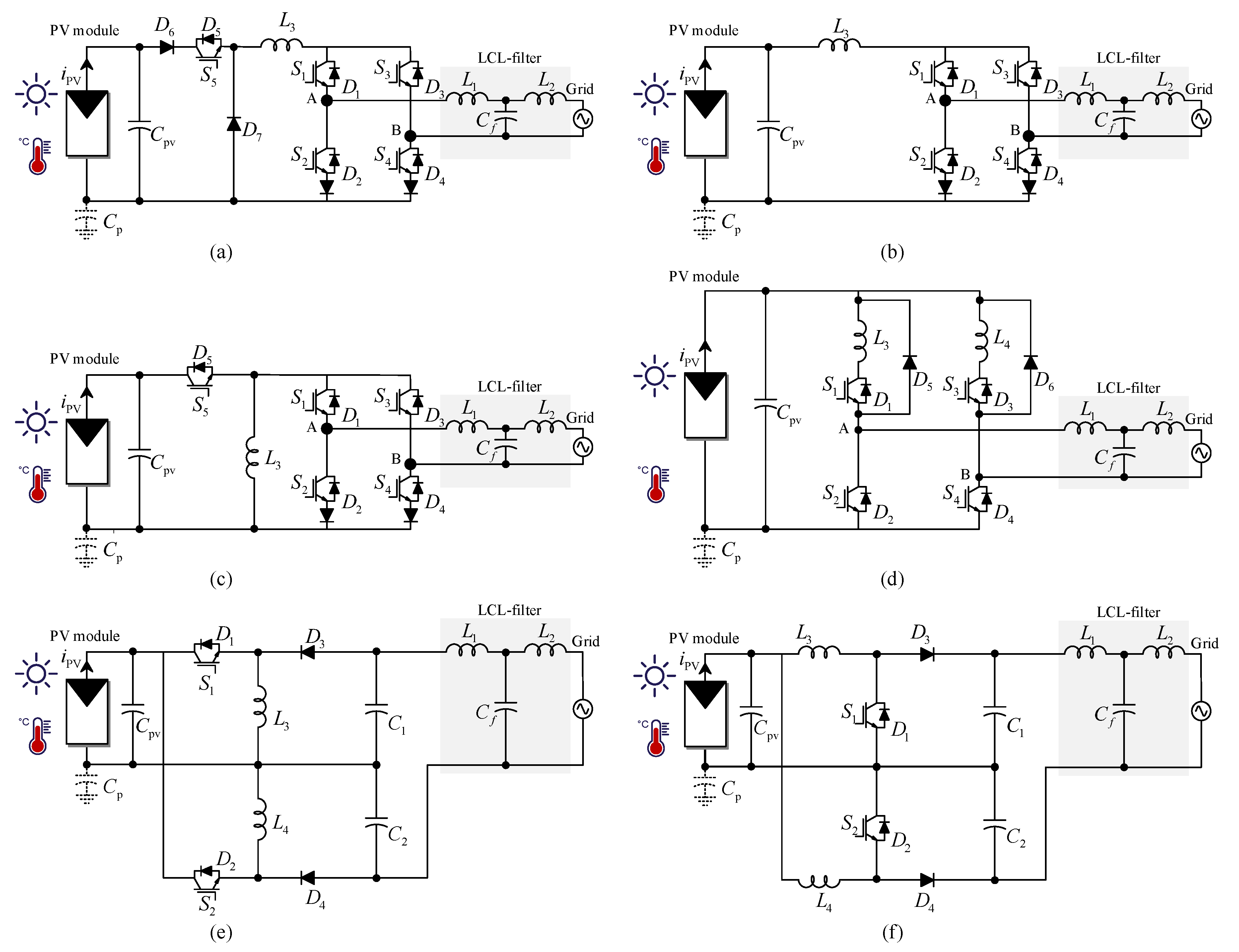
3.3. Pulsating DC-Link Voltage

The basic configuration of the pulsating dc-link inverter is presented in Figure 2c. These kinds of configurations are generally called impedance-source inverters [57,58]. Basic impedance-source inverters can be generalized as a two-port network with a general inverter. The impedance-source network was originally invented to overcome the limitations of the voltage-source inverter and current-source inverter topologies [59]. Considering the operating process of the impedance-source converter, the pulsating dc-link inverter can be regarded as a single-stage inverter. The input source of these kind of converters can be a voltage source or current source. As the PV curve can be separated into the current and voltage zone, the pulsating dc-link inverter can transfer between these operating zones without any modification of the topology and with similar operating characteristics. By inserting the shoot-through states into the conventional modulation method, the impedance-source inverter can achieve boost capability. Compared with the constant dc-link inverter, the system cost decreases and the efficiency increases. The inverter working in active mode is similar to the constant dc-link inverter. All the shoot-through states are inserted into the original zero states, thus the original operation will not be affected. During the shoot-through states, the impedance-source network is “disconnected” from the inverter, which makes the dc-link voltage equal to zero [60,61]. The modulation methods for impedance-source inverters are derived from the conventional methods for voltage source inverters by modifying the reference [62]. Thus, these configurations show great potential for renewable applications. However, the introduction of the shoot-through states might deteriorate the common-mode voltage harmonics. Thus, special modulation methods and control techniques are essential for PV applications.
Figure 6a shows the first proposed Z-source inverter [63]. The Z-source network consists of two capacitors, two inductors and one diode. There is a diode in the positive part of the input, which makes the input current discontinuous. The dc-link voltage is pulsating, which increases the complexity of the controller design process. The control of the dc-link voltage can be divided into direct control and indirect control. If the Z-source inverter is controlled directly, some special measuring circuits are needed for detecting the peak value of the dc-link voltage, which is costly. Considering the indirect control, a variable can be chosen to be controlled constant, such as the voltage of the capacitor C 1 . However, the peak value of the dc-link voltage will vary as the input changes, which implies a high requirement for the switches. Figure 6b shows a T-source inverter with a coupled inductor, which can realize a higher boost gain by arranging the winding ratios [58]. A lot of boosting technologies can also be applied to modify the topology of the impedance-source inverter, for example, coupled inductors, voltage multiplier, switched inductor and so forth. In Figure 6c,d, two quasi-Z-source inverters are shown, which consist of the same components as the Z-source inverter [60,64]. The quasi-Z-source inverter inherits all the advantages of the Z-source inverter and can also operate with continuous input current. There is another advantage that the voltage stress on capacitor C 2 can be decreased dramatically. It can be observed that in the T-source network, two quasi-Z-source networks share the same ground as the input source, which introduces new issues for the common-mode voltage and leakage current when the shoot-through states are adopted in PV systems. These issues can also be mitigated by modifying the topology, for example, inserting a diode in the negative side of the input source, or symmetrical structure. Without additional control signals for the impedance-source network, the pulsating dc-link inverter can also save much cost and become a strong alternative of the conventional two-stage inverter.

3.4. Integrated DC-Link Voltage

To improve the efficiency of the whole system and reduce the number of the components, the step-up ability can be integrated into the inverter side, which presents no separate dc-link [65]. Thus, in this part, the integrated dc-link inverters are discussed. The integrated dc-link inverter can be separated into two inverters that share the same input and the same output [66,67]. The outputs of these two inverters have the same amplitudes but are in anti-phase. The output of the integrated dc-link inverter is the difference between these two inverters. Figure 7a presents a differential boost inverter, which generates a high voltage by connecting two boost converters differentially with output filters [68,69]. The two boost converters generate a unipolar sinusoidal voltage with a dc-bias. Figure 7b presents a buck-boost differential inverter with the same differential configuration. A universal single-stage buck-boost inverter is presented in Figure 7c, which can operate in a large range of input voltage. Figure 7d presents a simpler configuration of the single-stage buck-boost inverter to improve efficiency. Figure 7e,f present inverters that have two dc converters operate alternatively for the positive and negative grid voltage with the same input source [70].

4. Comparison of the Four Types of Topologies

In this part, some main challenges of the inverter configurations for PV applications, such as the boosting capability, number of semiconductor devices and passive components, power density, output quality, leakage current and switch voltage stress, are summarized for these four types of dc-link inverters. Compared with isolated high-step-up inverters, transformerless configurations can reduce the system cost and improve efficiency but also introduce the leakage current issue [71]. No conclusions can be drawn from these summaries which type is the best since these topologies are designed for different grid or residential requirements. Considering the general performance of these four dc-link types of inverters and some special topologies, the comparison between constant dc-link inverter, pseudo-dc-link inverter, pulsating dc-link inverter and integrated dc-link inverters are presented in Table 2 [72,73,74,75,76,77].
There is a bulky electrolytic input capacitor in parallel with the PV panels to smooth out the input voltage for pseudo-dc-link inverters and integrated dc-link inverters [13,78]. A small capacitor is generally placed in the dc-link of the constant dc-link inverter to decouple the dc and ac parts, which can extend the lifetime of the inverter. Since the dc-link of the impedance-source inverter is pulsating, there will be no capacitor at the dc-link. Similar to integrated dc-link inverters and pseudo-dc-link inverters, an input capacitor can be placed in parallel with the PV panels. Considering the cost and boosting capability, pulsating dc-link inverters show advantages over the other three types. No additional control signals needed for the front-end part and the modification of the modulation methods can achieve the boosting functions. Meanwhile, the front-end parts of the constant dc-link inverter and pseudo-dc-link inverter require additional modulators [79]. Even though there is no control part for the integrated dc-link inverter, the operation stress on the components are bigger, which increases the design cost of the system. The pulsating dc-link inverter can achieve much higher power density with the same cost. The number of the components in the constant dc-link inverter and pseudo-dc-link inverter can be the same. Thus, the cost and size of these two configurations are similar. The pulsating dc-link inverter and integrated dc-link inverter have a much smaller number of both passive and active components, which makes them cheaper than the constant dc-link inverter and pseudo-dc-link inverter. By switch multiplexing, the integrated dc-link inverter can achieve rather high power density. The pulsating dc-link inverters are strong nonlinear converters, thus, the boosting gain can be very high. In order to achieve the same boosting gain in case of the constant dc-link inverter, multi-level stages are generally necessary [80]. Meanwhile, both pulsating dc-link inverters and pseudo-dc-link inverters can operate as buck-boost inverters according to the input variations. When the input is larger than the peak value of the grid voltage, the pulsating dc-link inverters will operate as a normal H-bridge inverter and the pseudo-dc-link inverters will operate as a buck converter. For some special structures of the integrated dc-link inverters, such as the differential buck-boost inverter, the same operation process can be derived just like the pseudo-dc-link inverters.
The modulation methods for the constant dc-link inverters can be implemented in a simple way by comparing the reference with carrier wave. However, for the pseudo-dc-link inverter, the input voltage is compared with the grid voltage and then the reference will be calculated according to the operating mode of the inverter in either boost mode or buck mode. The reference of the pulsating dc-link inverter is calculated in similar way compared to the constant dc-link inverter, however, adding the shoot-through duty ratio is complex by modifying the sinusoidal pulse width modulation (SPWM) or space vector pulse width modulation (SVPWM). The modulation of the integrated dc-link inverter needs two sets of conventional modulators. Even though in case of constant dc-link inverters, the whole system is heavy, bulky and costly, the control process of this type of inverters is rather simple. The dc part and the ac part of the constant dc-link inverters are decoupled, which make these kind of inverters expendable with more multi-level stages to obtain the desired output dc-link voltage [81]. However, the pulsating dc-link inverters are vulnerable to input variations, which affect the dynamics of the system. The operation regions of the pseudo-dc-link inverters and integrated dc-link inverters are limited by the adopted dc-ac inverters, which in turn limit the operation power level.
For the pulsating dc-link inverter, the voltage sag might appear in the peak dc-link voltage when the switching state changes. Especially when the dc-link current cannot support the grid current, there will be distortion in the output current. The pseudo-dc-link inverter operates with low switching frequency, distortion appears in the output current during the zero crossing of the grid voltage. As for the integrated dc-link inverter, the parameter mismatch of the two separated inverters can also result in distortion and large dc current injection. Figure 8 shows the simulation results of the dc-link voltage and grid voltage waveform of the discussed PV inverters.

5. Conclusions

In this paper, transformerless step-up grid-connected single-phase inverters for PV applications were reviewed based on the type of the dc-link. Grid requirements from typical standards were summarized and compared in terms of harmonic level, injected dc current, voltage variations and frequency variations. The characteristics of the constant dc-link inverter, pseudo-dc-link inverter, pulsating dc-link inverter and integrated dc-link inverter were discussed. Future topologies can also be included based on the discussions. In addition, their features and effects on the performance of the generation system were also presented. In terms of the comparisons, the constant dc-link inverters cost more but have the advantages of modularity in structure and better output performance. Moreover, the pseudo-dc-link inverters can be a replacement when considering the size and cost compared constant dc-link inverters. Furthermore, leakage currents are expected to be lower in pseudo-dc-link inverters due to the low-frequency unfolding circuit. The pulsating dc-link inverter shows almost the same operating features as the constant dc-link inverter but no additional dc part control signal is needed. The integrated dc-link inverters show higher requirements for the semiconductor devices and control process. Meanwhile, the injected dc currents are hard to eliminate. The pseudo-dc-link inverter and pulsating dc-link inverter on the other hand can be alternatives for conventional constant dc-link inverters in most applications but the special features of these inverters should be considered carefully. The integrated dc-link inverters are especially suitable for low power applications. Based on the presented classification of the different dc-link inverters, the selection or modification of certain kinds of PV inverters for special applications can be more straightforward.

Author Contributions

W.L. wrote the paper, W.L. and K.A.K.N. designed the structures of the paper and PV system related work; T.K. and Y.Y. reviewed and editing the paper.

Funding

This research received no external funding.

Acknowledgments

The authors would like to thank the China Scholarship Council for supporting the study in the Department of Energy Technology, Aalborg University.

Conflicts of Interest

The authors declare no conflict of interest.

References

  1. Yang, X.; Song, Y.; Wang, G.; Wang, W. A Comprehensive Review on the Development of Sustainable Energy Strategy and Implementation in China. IEEE Trans. Sustain. Energy 2010, 1, 57–65. [Google Scholar] [CrossRef]
  2. Blaabjerg, F.; Yang, Y.; Yang, D.; Wang, X. Distributed Power-Generation Systems and Protection. Proc. IEEE 2017, 105, 1311–1331. [Google Scholar] [CrossRef] [Green Version]
  3. Kasper, M.; Bortis, D.; Kolar, J.W. Classification and Comparative Evaluation of PV Panel-Integrated DC–DC Converter Concepts. IEEE Trans. Power Electron. 2014, 29, 2511–2526. [Google Scholar] [CrossRef]
  4. REN 21. Renewables 2019: Global Status Report (GSR); Technical Report; REN21 Secretariat: Paris, France, 2019. [Google Scholar]
  5. SolarPower Europe. Global Market Outlook For Solar Power 2019–2023; Technical Report; SolarPower Europe: Brussels, Belgium, 2019. [Google Scholar]
  6. Niazi, K.A.K.; Yang, Y.; Sera, D. Review of Mismatch Mitigation Techniques for PV Modules. IET Renew. Power Gener. 2019, 13, 2035–2050. [Google Scholar] [CrossRef]
  7. Hu, H.; Harb, S.; Kutkut, N.; Batarseh, I.; Shen, Z.J. A Review of Power Decoupling Techniques for Microinverters with Three Different Decoupling Capacitor Locations in PV Systems. IEEE Trans. Power Electron. 2013, 28, 2711–2726. [Google Scholar] [CrossRef]
  8. Patel, H.; Agarwal, V. MPPT Scheme for a PV-Fed Single-Phase Single-Stage Grid-Connected Inverter Operating in CCM With Only One Current Sensor. IEEE Trans. Energy Convers. 2009, 24, 256–263. [Google Scholar] [CrossRef] [Green Version]
  9. Li, Q.; Wolfs, P. A Review of the Single Phase Photovoltaic Module Integrated Converter Topologies With Three Different DC Link Configurations. IEEE Trans. Power Electron. 2008, 23, 1320–1333. [Google Scholar]
  10. Forouzesh, M.; Siwakoti, Y.P.; Gorji, S.A.; Blaabjerg, F.; Lehman, B. Step-Up DC–DC Converters: A Comprehensive Review of Voltage-Boosting Techniques, Topologies, and Applications. IEEE Trans. Power Electron. 2017, 32, 9143–9178. [Google Scholar] [CrossRef]
  11. Yang, Y.; Enjeti, P.; Blaabjerg, F.; Wang, H. Wide-Scale Adoption of Photovoltaic Energy: Grid Code Modifications Are Explored in the Distribution Grid. IEEE Ind. Appl. Mag. 2015, 21, 21–31. [Google Scholar] [CrossRef] [Green Version]
  12. Adefarati, T.; Bansal, R.C. Integration of Renewable Distributed Generators into the Distribution System: A Review. IET Renew. Power Gener. 2016, 10, 873–884. [Google Scholar] [CrossRef]
  13. Carrasco, J.M.; Franquelo, L.G.; Bialasiewicz, J.T.; Galvan, E.; PortilloGuisado, R.C.; Prats, M.A.M.; Leon, J.I.; Moreno-Alfonso, N. Power-Electronic Systems for the Grid Integration of Renewable Energy Sources: A Survey. IEEE Trans. Ind. Electron. 2006, 53, 1002–1016. [Google Scholar] [CrossRef]
  14. Yang, Y.; Blaabjerg, F. Overview of Single-Phase Grid-Connected Photovoltaic Systems. Electr. Power Compon. Syst. 2015, 43, 1352–1363. [Google Scholar] [CrossRef]
  15. Wu, Y.; Lin, J.; Lin, H. Standards and Guidelines for Grid-Connected Photovoltaic Generation Systems: A Review and Comparison. IEEE Trans. Ind. Appl. 2017, 53, 3205–3216. [Google Scholar] [CrossRef]
  16. Gu, B.; Dominic, J.; Lai, J.; Chen, C.; LaBella, T.; Chen, B. High Reliability and Efficiency Single-Phase Transformerless Inverter for Grid-Connected Photovoltaic Systems. IEEE Trans. Power Electron. 2013, 28, 2235–2245. [Google Scholar] [CrossRef]
  17. Yang, B.; Li, W.; Gu, Y.; Cui, W.; He, X. Improved Transformerless Inverter With Common-Mode Leakage Current Elimination for a Photovoltaic Grid-Connected Power System. IEEE Trans. Power Electron. 2012, 27, 752–762. [Google Scholar] [CrossRef]
  18. Subudhi, B.; Pradhan, R. A Comparative Study on Maximum Power Point Tracking Techniques for Photovoltaic Power Systems. IEEE Trans. Sustain. Energy 2013, 4, 89–98. [Google Scholar] [CrossRef]
  19. Li, W.; Gu, Y.; Luo, H.; Cui, W.; He, X.; Xia, C. Topology Review and Derivation Methodology of Single-Phase Transformerless Photovoltaic Inverters for Leakage Current Suppression. IEEE Trans. Ind. Electron. 2015, 62, 4537–4551. [Google Scholar] [CrossRef]
  20. Xue, Y.; Chang, L.; Kjaer, S.B.; Bordonau, J.; Shimizu, T. Topologies of Single-Phase Inverters for Small Distributed Power Generators: An Overview. IEEE Trans. Power Electron. 2004, 19, 1305–1314. [Google Scholar] [CrossRef]
  21. Zhao, Z.; Xu, M.; Chen, Q.; Lai, J.; Cho, Y. Derivation, Analysis, and Implementation of a Boost–Buck Converter-Based High-Efficiency PV Inverter. IEEE Trans. Power Electron. 2012, 27, 1304–1313. [Google Scholar] [CrossRef]
  22. Chub, A.; Vinnikov, D.; Blaabjerg, F.; Peng, F.Z. A Review of Galvanically Isolated Impedance-Source DC–DC Converters. IEEE Trans. Power Electron. 2016, 31, 2808–2828. [Google Scholar] [CrossRef]
  23. Xiao, W.; Moursi, M.S.E.; Khan, O.; Infield, D. Review of Grid-Tied Converter Topologies Used in Photovoltaic Systems. IET Renew. Power Gener. 2016, 10, 1543–1551. [Google Scholar] [CrossRef]
  24. Meneses, D.; Blaabjerg, F.; García, Ó.; Cobos, J.A. Review and Comparison of Step-Up Transformerless Topologies for Photovoltaic AC-Module Application. IEEE Trans. Power Electron. 2013, 28, 2649–2663. [Google Scholar] [CrossRef]
  25. Deutsches Institut fur Normung (DIN); Verband der Elektrotechnik Elektronik Informationstechnik (VDE) e.V. Automatic Disconnection Device between a Generator and the Public Low Voltage Grid; VDE V 0126-1-1 2006-02; Deutsches Institut fur Normung (DIN): Berlin, Germnay; Verband der Elektrotechnik Elektronik Informationstechnik (VDE) e.V.: Frankfurt, Germany, 2006. [Google Scholar]
  26. International Electrotechnical Commission. Photovoltaic (PV) Systems—Characteristics of the Utility Interface; IEC Stand. 61727 Ed20; International Electrotechnical Commission: Geneva, Switzerland, 2004. [Google Scholar]
  27. IEEE. IEEE Application Guide for IEEE Std 1547(TM), IEEE Standard for Interconnecting Distributed Resources with Electric Power Systems; IEEE Std 15472-2008; IEEE: Piscataway, NJ, USA, 2009; pp. 1–217. [Google Scholar]
  28. Mastromauro, R.A.; Liserre, M.; Dell’Aquila, A. Control Issues in Single-Stage Photovoltaic Systems: MPPT, Current and Voltage Control. IEEE Trans. Ind. Inform. 2012, 8, 241–254. [Google Scholar] [CrossRef]
  29. Arshadi, S.A.; Poorali, B.; Adib, E.; Farzanehfard, H. High Step-Up DC–AC Inverter Suitable for AC Module Applications. IEEE Trans. Ind. Electron. 2016, 63, 832–839. [Google Scholar] [CrossRef]
  30. Barater, D.; Lorenzani, E.; Concari, C.; Franceschini, G.; Buticchi, G. Recent Advances in Single-Phase Transformerless Photovoltaic Inverters. IET Renew. Power Gener. 2016, 10, 260–273. [Google Scholar] [CrossRef]
  31. Akpınar, E.; Balıkcı, A.; Durbaba, E.; Azizoğlu, B.T. Single-Phase Transformerless Photovoltaic Inverter With Suppressing Resonance in Improved H6. IEEE Trans. Power Electron. 2019, 34, 8304–8316. [Google Scholar] [CrossRef]
  32. Ahmed, M.E.; Orabi, M.; Abdelrahim, O.M. Two-Stage Micro-Grid Inverter with High-Voltage Gain for Photovoltaic Applications. IET Power Electron. 2013, 6, 1812–1821. [Google Scholar] [CrossRef]
  33. Loh, P.C.; Blaabjerg, F.; Wong, C.P.; Tan, P.C. Tri-State Current Source Inverter WithImproved Dynamic Performance. IEEE Trans. Power Electron. 2008, 23, 1631–1640. [Google Scholar]
  34. Khateb, A.H.E.; Rahim, N.A.; Selvaraj, J.; Williams, B.W. DC-to-DC Converter With Low Input Current Ripple for Maximum Photovoltaic Power Extraction. IEEE Trans. Ind. Electron. 2015, 62, 2246–2256. [Google Scholar] [CrossRef]
  35. Wu, L.; Zhao, Z.; Liu, J. A Single-Stage Three-Phase Grid-Connected Photovoltaic System with Modified MPPT Method and Reactive Power Compensation. IEEE Trans. Energy Convers. 2007, 22, 881–886. [Google Scholar]
  36. Freddy, T.K.S.; Rahim, N.A.; Hew, W.; Che, H.S. Comparison and Analysis of Single-Phase Transformerless Grid-Connected PV Inverters. IEEE Trans. Power Electron. 2014, 29, 5358–5369. [Google Scholar] [CrossRef]
  37. Blaabjerg, F.; Chen, Z.; Kjaer, S.B. Power Electronics as Efficient Interface in Dispersed Power Generation Systems. IEEE Trans. Power Electron. 2004, 19, 1184–1194. [Google Scholar] [CrossRef]
  38. Martins, J.; Spataru, S.; Sera, D.; Stroe, D.I.; Lashab, A. Comparative Study of Ramp-Rate Control Algorithms for PV with Energy Storage Systems. Energies 2019, 12, 1342. [Google Scholar] [CrossRef]
  39. Araujo, S.V.; Zacharias, P.; Mallwitz, R. Highly Efficient Single-Phase Transformerless Inverters for Grid-Connected Photovoltaic Systems. IEEE Trans. Ind. Electron. 2010, 57, 3118–3128. [Google Scholar] [CrossRef]
  40. Xue, Y.; Chang, L.; Song, P. Recent Developments in Topologies of Single-Phase Buck-Boost Inverters for Small Distributed Power Generators: An Overview. In Proceedings of the 4th International Power Electronics and Motion Control Conference (IPEMC 2004), Xi’an, China, 14–16 August 2004; Volume 3, pp. 1118–1123. [Google Scholar]
  41. Shen, J.; Jou, H.; Wu, J. Novel Transformerless Grid-Connected Power Converter With Negative Grounding for Photovoltaic Generation System. IEEE Trans. Power Electron. 2012, 27, 1818–1829. [Google Scholar] [CrossRef]
  42. Kerekes, T.; Teodorescu, R.; Rodriguez, P.; Vazquez, G.; Aldabas, E. A New High-Efficiency Single-Phase Transformerless PV Inverter Topology. IEEE Trans. Ind. Electron. 2011, 58, 184–191. [Google Scholar] [CrossRef]
  43. Nabae, A.; Takahashi, I.; Akagi, H. A New Neutral-Point-Clamped PWM Inverter. IEEE Trans. Ind. Appl. 1981, A-17, 518–523. [Google Scholar]
  44. Calais, M.; Agelidis, V.G. Multilevel Converters for Single-Phase Grid Connected Photovoltaic Systems—An Overview. In Proceedings of the IEEE International Symposium on Industrial Electronics (ISIE’98), Pretoria, South Africa, 7–10 July 1998; Cat. No.98TH8357. Volume 1, pp. 224–229. [Google Scholar]
  45. Vázquez, N.; Rosas, M.; Hernández, C.; Vázquez, E.; Perez-Pinal, F.J. A New Common-Mode Transformerless Photovoltaic Inverter. IEEE Trans. Ind. Electron. 2015, 62, 6381–6391. [Google Scholar] [CrossRef]
  46. Bastidas-Rodriguez, J.D.; Franco, E.; Petrone, G.; Ramos-Paja, C.A.; Spagnuolo, G. Maximum Power Point Tracking Architectures for Photovoltaic Systems in Mismatching Conditions: A Review. IET Power Electron. 2014, 7, 1396–1413. [Google Scholar] [CrossRef]
  47. Koizumi, H.; Mizuno, T.; Kaito, T.; Noda, Y.; Goshima, N.; Kawasaki, M.; Nagasaka, K.; Kurokawa, K. A Novel Microcontroller for Grid-Connected Photovoltaic Systems. IEEE Trans. Ind. Electron. 2006, 53, 1889–1897. [Google Scholar] [CrossRef]
  48. Fang, Y.; Ma, X. A Novel PV Microinverter With Coupled Inductors and Double-Boost Topology. IEEE Trans. Power Electron. 2010, 25, 3139–3147. [Google Scholar] [CrossRef]
  49. Wang, Y.; Xue, L.; Wang, C.; Wang, P.; Li, W. Interleaved High-Conversion-Ratio Bidirectional DC–DC Converter for Distributed Energy-Storage Systems—Circuit Generation, Analysis, and Design. IEEE Trans. Power Electron. 2016, 31, 5547–5561. [Google Scholar] [CrossRef]
  50. Mirhosseini, M.; Pou, J.; Agelidis, V.G. Single- and Two-Stage Inverter-Based Grid-Connected Photovoltaic Power Plants With Ride-Through Capability Under Grid Faults. IEEE Trans. Sustain. Energy 2015, 6, 1150–1159. [Google Scholar] [CrossRef]
  51. Sun, Y.; Liu, Y.; Su, M.; Xiong, W.; Yang, J. Review of Active Power Decoupling Topologies in Single-Phase Systems. IEEE Trans. Power Electron. 2016, 31, 4778–4794. [Google Scholar] [CrossRef]
  52. Niazi, K.A.K.; Yang, Y.; Nasir, M.; Sera, D. Evaluation of Interconnection Configuration Schemes for PV Modules with Switched-Inductor Converters under Partial Shading Conditions. Energies 2019, 12, 2802. [Google Scholar] [CrossRef]
  53. Gonzalez, R.; Lopez, J.; Sanchis, P.; Marroyo, L. Transformerless Inverter for Single-Phase Photovoltaic Systems. IEEE Trans. Power Electron. 2007, 22, 693–697. [Google Scholar] [CrossRef]
  54. Wang, C.M. A Novel Single-Stage Full-Bridge Buck-Boost Inverter. IEEE Trans. Power Electron. 2004, 19, 150–159. [Google Scholar] [CrossRef]
  55. Romero-Cadaval, E.; Spagnuolo, G.; Franquelo, L.G.; Ramos-Paja, C.A.; Suntio, T.; Xiao, W.M. Grid-Connected Photovoltaic Generation Plants: Components and Operation. IEEE Ind. Electron. Mag. 2013, 7, 6–20. [Google Scholar] [CrossRef] [Green Version]
  56. Buticchi, G.; Barater, D.; Lorenzani, E.; Franceschini, G. Digital Control of Actual Grid-Connected Converters for Ground Leakage Current Reduction in PV Transformerless Systems. IEEE Trans. Ind. Inform. 2012, 8, 563–572. [Google Scholar] [CrossRef]
  57. Siwakoti, Y.P.; Peng, F.Z.; Blaabjerg, F.; Loh, P.C.; Town, G.E.; Yang, S. Impedance-Source Networks for Electric Power Conversion Part II: Review of Control and Modulation Techniques. IEEE Trans. Power Electron. 2015, 30, 1887–1906. [Google Scholar] [CrossRef]
  58. Siwakoti, Y.P.; Peng, F.Z.; Blaabjerg, F.; Loh, P.C.; Town, G.E. Impedance-Source Networks for Electric Power Conversion Part I: A Topological Review. IEEE Trans. Power Electron. 2015, 30, 699–716. [Google Scholar] [CrossRef]
  59. Siwakoti, Y.P.; Blaabjerg, F. Common-Ground-Type Transformerless Inverters for Single-Phase Solar Photovoltaic Systems. IEEE Trans. Ind. Electron. 2018, 65, 2100–2111. [Google Scholar] [CrossRef]
  60. Ellabban, O.; Abu-Rub, H. Z-Source Inverter: Topology Improvements Review. IEEE Ind. Electron. Mag. 2016, 10, 6–24. [Google Scholar] [CrossRef]
  61. Anderson, J.; Peng, F.Z. Four Quasi-Z-Source Inverters. In Proceedings of the 2008 IEEE Power Electronics Specialists Conference, Rhodes, Greece, 15–19 June 2008; pp. 2743–2749. [Google Scholar]
  62. Yang, S.; Peng, F.Z.; Lei, Q.; Inoshita, R.; Qian, Z. Current-Fed Quasi-Z-Source Inverter With Voltage Buck–Boost and Regeneration Capability. IEEE Trans. Ind. Appl. 2011, 47, 882–892. [Google Scholar] [CrossRef]
  63. Peng, F.Z. Z-Source Inverter. IEEE Trans. Ind. Appl. 2003, 39, 504–510. [Google Scholar] [CrossRef]
  64. Saridakis, S.; Koutroulis, E.; Blaabjerg, F. Optimal Design of Modern Transformerless PV Inverter Topologies. IEEE Trans. Energy Convers. 2013, 28, 394–404. [Google Scholar] [CrossRef] [Green Version]
  65. Kjaer, S.B.; Pedersen, J.K.; Blaabjerg, F. A Review of Single-Phase Grid-Connected Inverters for Photovoltaic Modules. IEEE Trans. Ind. Appl. 2005, 41, 1292–1306. [Google Scholar] [CrossRef]
  66. Melo, F.C.; Garcia, L.S.; de Freitas, L.C.; Coelho, E.A.A.; Farias, V.J.; de Freitas, L.C.G. Proposal of a Photovoltaic AC-Module With a Single-Stage Transformerless Grid-Connected Boost Microinverter. IEEE Trans. Ind. Electron. 2018, 65, 2289–2301. [Google Scholar] [CrossRef]
  67. Prasad, B.S.; Jain, S.; Agarwal, V. Universal Single-Stage Grid-Connected Inverter. IEEE Trans. Energy Convers. 2008, 23, 128–137. [Google Scholar] [CrossRef]
  68. Patel, H.; Agarwal, V. A Single-Stage Single-Phase Transformer-Less Doubly Grounded Grid-Connected PV Interface. IEEE Trans. Energy Convers. 2009, 24, 93–101. [Google Scholar] [CrossRef]
  69. Jain, S.; Agarwal, V. A Single-Stage Grid Connected Inverter Topology for Solar PV Systems with Maximum Power Point Tracking. IEEE Trans. Power Electron. 2007, 22, 1928–1940. [Google Scholar] [CrossRef]
  70. Kang, F.-S.; Kim, C.-U.; Park, S.-J.; Park, H.-W. Interface Circuit for Photovoltaic System Based on Buck-Boost Current-Source PWM Inverter. In Proceedings of the IEEE 2002 28th Annual Conference of the Industrial Electronics Society (IECON 02), Sevilla, Spain, 5–8 November 2002; Volume 4, pp. 3257–3261. [Google Scholar]
  71. Xiao, H.; Xie, S. Interleaving Double-Switch Buck-Boost Converter. IET Power Electron. 2012, 5, 899–908. [Google Scholar] [CrossRef]
  72. Guo, X.; Zhou, J.; He, R.; Jia, X.; Rojas, C.A. Leakage Current Attenuation of a Three-Phase Cascaded Inverter for Transformerless Grid-Connected PV Systems. IEEE Trans. Ind. Electron. 2018, 65, 676–686. [Google Scholar] [CrossRef]
  73. Xiao, H.; Xie, S. Leakage Current Analytical Model and Application in Single-Phase Transformerless Photovoltaic Grid-Connected Inverter. IEEE Trans. Electromagn. Compat. 2010, 52, 902–913. [Google Scholar] [CrossRef]
  74. López, Ó.; Freijedo, F.D.; Yepes, A.G.; Fernández-Comesaña, P.; Malvar, J.; Teodorescu, R.; Doval-Gandoy, J. Eliminating Ground Current in a Transformerless Photovoltaic Application. IEEE Trans. Energy Convers. 2010, 25, 140–147. [Google Scholar] [CrossRef]
  75. Herran, M.A.; Fischer, J.R.; Gonzalez, S.A.; Judewicz, M.G.; Carrica, D.O. Adaptive Dead-Time Compensation for Grid-Connected PWM Inverters of Single-Stage PV Systems. IEEE Trans. Power Electron. 2013, 28, 2816–2825. [Google Scholar] [CrossRef]
  76. Wu, T.; Chang, C.; Lin, L.; Kuo, C. Power Loss Comparison of Single- and Two-Stage Grid-Connected Photovoltaic Systems. IEEE Trans. Energy Convers. 2011, 26, 707–715. [Google Scholar] [CrossRef]
  77. Yu, W.; Lai, J.J.; Qian, H.; Hutchens, C. High-Efficiency MOSFET Inverter with H6-Type Configuration for Photovoltaic Nonisolated AC-Module Applications. IEEE Trans. Power Electron. 2011, 26, 1253–1260. [Google Scholar] [CrossRef]
  78. Caceres, R.O.; Barbi, I. A Boost DC-AC Converter: Analysis, Design, and Experimentation. IEEE Trans. Power Electron. 1999, 14, 134–141. [Google Scholar] [CrossRef]
  79. Gonzalez, R.; Gubia, E.; Lopez, J.; Marroyo, L. Transformerless Single-Phase Multilevel-Based Photovoltaic Inverter. IEEE Trans. Ind. Electron. 2008, 55, 2694–2702. [Google Scholar] [CrossRef]
  80. Tang, Y.; Yao, W.; Loh, P.C.; Blaabjerg, F. Highly Reliable Transformerless Photovoltaic Inverters with Leakage Current and Pulsating Power Elimination. IEEE Trans. Ind. Electron. 2016, 63, 1016–1026. [Google Scholar] [CrossRef]
  81. Georgakas, K.G.; Vovos, P.N.; Vovos, N.A. Harmonic Reduction Method for a Single-Phase DC–AC Converter Without an Output Filter. IEEE Trans. Power Electron. 2014, 29, 4624–4632. [Google Scholar] [CrossRef]
Figure 1. Grid-connected photovoltaice (PV) systems with: (a) module structure, (b) string structure, (c) multi-string structure and (d) central structure.
Energies 12 03626 g001
Figure 2. General block diagram of single-phase PV inverter systems with: (a) constant dc-link structure; (b) pseudo-dc-link structure; (c) pulsating dc-link structure and (d) integrated dc-link structure.
Energies 12 03626 g002
Figure 3. (a) Half-bridge inverter, (b) full-bridge inverter, (c) H5 inverter, (d) H6D1 inverter, (e) H6D2 inverter, (f) HERIC inverter, (g) HB-ZVR and (h) half-bridge three-level NPC inverter, (i) full-bridge five-level NPC inverter.
Energies 12 03626 g003
Figure 4. Two-stage grid-connected single-phase PV inverter with constant dc-link voltage consisting of—(a) a boost converter and a full-bridge inverter with an LCL filter, (b) a quadratic boost converter and a full-bridge inverter with an LCL filter, (c) a three-level boost converter and a full-bridge inverter with an LCL filter, (d) an interleaved boost converter and a full-bridge inverter with an LCL filter, (e) a time-sharing boost converter and a full-bridge inverter with an LCL filter and (f) cascaded boost converters and a full-bridge inverter with an LCL filter.
Energies 12 03626 g004
Figure 5. Grid-connected single-phase PV inverter with pseudo-dc-link voltage consisting of: (a) a boost converter and a unfolding inverter with an LCL filter, (b) a buck-boost converter and a unfolding inverter with an LCL filter, (c) a noninverting buck-boost converter and a unfolding inverter with an LCL filter and (d) a switched-inductor buck–boost and a unfolding inverter with an LCL filter.
Energies 12 03626 g005
Figure 6. Grid-connected single-phase impedance-source inverter with pulsating dc-link voltage consisting of: (a) a Z-source network and a full-bridge inverter with an LCL filter, (b) a T-source network converter and a full-bridge inverter with an LCL filter, (c) a input continuous Z-source network and a full-bridge inverter with an LCL filter, (d) a quasi-Z-source network and a full-bridge inverter with an LCL filter.
Energies 12 03626 g006
Figure 7. Grid-connected single-phase single-stage inverter with integrated dc-link voltage: (a) a universal single-stage inverter with an LCL filter, (b) an integrated boost inverter with an LCL filter, (c) an improved integrated boost inverter with an LCL filter, (d) a full-bridge buck-boost inverter with an LCL filter, (e) a differential buck–boost inverter with an LCL filter and (f) a differential boost inverter with an LCL filter.
Energies 12 03626 g007
Figure 8. Typical dc-link voltage and grid voltage waveform of: (a) constant dc-link inverters, (b) pseudo-dc-link inverters, (c) pulsating dc-link inverters and (d) integrated dc-link inverters.
Energies 12 03626 g008
Table 1. Summary of the grid requirements in different standards.
IEEE 1547 [25]IEC 61727 [26]VDE0126-1-1 [27]
Nominal
power
30 kW10 kW-
Harmonic
level
Order%Order%OrderA
3–94.03–94.033
11–152.011–152.051.5
17–211.517–211.571
23–330.623–330.690.7
>350.3>350.3110.33
130.4
even harmonics < 25% of odd harmonicseven1.5/h
total harmonics distortion (THD) < 5%>404.5/h
DC
current
<1% of rated current<0.5% of rated current<0.22 A
Votlage
variation
V < 50%0.1 sV < 50%0.16 sV < 85%0.2 s
50% < V < 88%2 s50% < V < 88%2 sV > 110%0.2 s
110% < V < 120%2 s110% <V < 120%1 s
V > 120%0.05 sV > 120%0.16 s
Frequency
variation
49 Hz < f < 49 Hz0.2 s59.3 Hz < f < 60.5 Hz0.16 s47.5 Hz < f < 50.2 Hz0.2 s
Table 2. Comparisons of these four dc-link types of step-up transformerless inverters.
DC-LinkAdvantageDisadvantage
ConstantHigh voltage level;Large amount of components;
High power capability;Heavy, bulky and costly;
Reliable output;Low efficiency;
Modularity structure;Multi-level needed for higher boosting gain;
Easy to control with dc and ac decoupled.Leakage current depends on the topologies;
Limited operation regions.
PseudoLow switching frequency;Output distortion when input varies;
High power desnsity;Zero-crossing distortion;
Less hardware cost;Limited boosting capability;
Buck-boost capability;Higher requirements for modulation;
High efficiency;High requirements for front-end converters;
Low leakage current.More semiconductor devices needed.
PulsatingInvulnerable to EMI;Control complexity;
High power density;Higher requirements for modulation;
High boosting capability;Large leakage current;
High efficiency;Higher common-mode voltage harmonics;
Less hardware cost;Vulnerable to input variations;
Buck-boost capability.Voltage sag between switching states.
IntegratedHigh power density;Distortion from the parameter mismatch;
Switch multiplexing;Large injected dc current;
Less hardware cost;Small power applications;
Less semiconductor devices;Zero-crossing distortion in some topologies;
Smaller leakage current.Higher operation stress on the components.

