Article

Empirical Study on the Efficiency of an LPG-Supplied Range Extender for Electric Vehicles

Faculty of Automotive and Construction Machinery Engineering, Warsaw University of Technology, 02-524 Warsaw, Poland
*
Author to whom correspondence should be addressed.
Energies 2019, 12(18), 3528; https://doi.org/10.3390/en12183528
Submission received: 4 August 2019 / Revised: 6 September 2019 / Accepted: 11 September 2019 / Published: 13 September 2019
(This article belongs to the Section E: Electric Vehicles)

Abstract

:
A range extender is an auxiliary power unit, usually consisting of an internal combustion engine and an electric generator, which is used to charge a battery of an electric vehicle in order to increase its range. This paper considers a range extender supplied with liquefied petroleum gas (LPG). The aim is to provide detailed data on thermal efficiency, brake specific fuel consumption (BSFC), and unit emission of carbon dioxide (CO2) in a broad spectrum of range extender operating conditions defined by rotational speed and torque. The experimental investigation has been conducted using a laboratory test stand equipped with an energy dissipation system of adjustable resistance. Measurement results, including fuel flow rate, were processed using custom algorithm for generating maps, i.e., two-dimensional dependencies of the considered parameters on the rotational speed and torque. The maps obtained for LPG supply were compared with those for gasoline supply. The results demonstrated feasibility of LPG-supplied range extender. Its BSFC and thermal efficiency were at a comparable level to those obtained for gasoline supply, but with less CO2 emission. The empirical data collected has been adopted in the simulation of extended-range electric vehicle in a driving cycle, showing the potential of utilizing the results of this study.

1. Introduction

The number of electric vehicles (EVs) worldwide is growing rapidly and their future development prospects are excellent [1]. Vehicle electrification is the way forward for the automotive industry looking to address two main environmental challenges of road transportation: air pollution and depletion of crude oil reserves [2]. A major concern is air quality degradation in urban areas and its implications on human health [3]. The most effective solution that towns and cities can take to counteract this issue is the introduction of clean air (zero/low emission) zones. This promotes the use of battery-electric vehicles (BEVs) that do not produce exhaust emissions, unlike conventional vehicles with internal combustion engines (ICEs) [4]. Other advantages of BEVs, including high efficiency of the powertrain and recuperative braking [5] or good prospects for the introduction of automatic steering systems [6,7], make them become competitive, especially for intraurban, short-distance applications such as commercial fleets or commuter vehicles [8]. However, BEVs are unlikely to substitute for ICE-based vehicles in long-distance applications unless a major breakthrough in battery technology is achieved. Due to high cost and limited capacity of currently used batteries, to store energy to provide satisfactory driving range for BEVs is not always possible [1].
The importance of providing adequate driving range to BEVs users has led to the development of extended range electric vehicles (EREVs), which combine an electric powertrain with an ICE [9,10] (Figure 1). Their principle of operation is same as that of a standard BEVs, with the only difference being that an additional ICE acts as an on-board generator (range extender) to recharge the battery [11]. EREVs operate exclusively as BEVs when battery energy is available and have full performance in electric mode (e.g., top speed, acceleration capability) [12]. This is possible owing to EREV’s electric propulsion system and battery sized in such a way that the ICE is not required for vehicle operation as long as battery energy is available [12]. It is therefore preferable to move the vehicle with the use of an electric motor only, i.e., in "zero emission" driving mode, but at the same time, the user is not afraid of running out of battery energy, and so called “range anxiety” (the term was introduced in the late 1990s [13]) is alleviated.
Despite their practicality, EREVs are not an ideal solution because the use of an onboard ICE to ensure sufficient range of the vehicle results in emission of pollutants. Recently, it has been proposed to limit this emission by supplying range extenders with alternative fuels [9,11,14,15]. While there are many gaseous and liquid fuels to consider [16], the use of liquified petroleum gas (LPG) and its renewable version, BioLPG, are considered as currently viable options [11,17,18]. They offer not only significant possibility to limit emission of harmful substances, but also good cost effectiveness over existing range extension technologies utilizing gasoline and diesel engines [11,19]. However, due to the early phase of development of this solution, range extenders supplied with LPG have not yet been sufficiently tested and there is a very small number of scientific publications devoted to this topic.
Recently it has been proved that EREVs can be successfully implemented in commercial applications. Several car manufacturers offer EREVs for sale, e.g., BMW i3-REX, Chevrolet VOLT/Opel Ampera, other companies supporting the automotive industry, e.g., AVL, KSPG, Lotus Engineering, MAHLE, have presented their own range extender concepts as modules for use in vehicles [20]. Most of them make use of spark ignition ICEs. BMW converted small-displacement two-cylinder ICE used in the BMW C650 GT scooter [21] to be offered as an option for the BMW i3, initially designed as a pure BEV. General Motors has chosen a different way by designing the Voltec powertrain [22,23], formerly known as E-Flex, which includes an all-new four-cylinder Ecotec ICE [24], exclusively for Chevrolet Volt/Opel Ampera. Voltec architecture is similar to a plug-in hybrid (PHEV), but is capable of operation on battery power alone up to 85 km, depending on the driving style, ambient temperature conditions, and climate comfort settings [23]. AVL has developed several different solutions for range extenders including rotary (Wankel) engine as well as single- and two-cylinder reciprocating piston engines derived from motorcycle applications [25,26]. A similar approach was taken by MAHLE, which has presented a compact two-cylinder ICE-based range extender with a focus on the efficiency and noise optimization [27,28]. Likewise, Lotus Engineering aims at an extremely compact, lightweight, multifuel capability, low-cost range extender based on a three-cylinder ICE [29], and is planning to show the supercharged version. Finally, Tata Motors Europe in cooperation with Bath University developed a range extender from a production two-cylinder ICE for the Indian market [30].
Further development of EREVs is expected to be determined by the progress in powertrain control strategy for better energy efficiency management. It is possible to optimize the exploitation of two separate energy sources in order to reduce energy consumption and pollutant emissions, taking into account actual conditions of vehicle use and driver needs [19,31]. An essential variable is the brake-specific fuel consumption (BSFC) or thermal efficiency of the range extender at a given operating state, which in turn depends on the joint efficiencies of an ICE and a generator. BSFC is determined empirically and presented in the form of the so-called maps illustrating its dependence on rotational speed and load [32]. Although such maps form the basis of simulation studies, it is very difficult to obtain them from the literature. There are excellent quality BSFC/thermal efficiency maps available for ICEs (e.g., [33]), including those supplied with LPG (e.g., [34]), but there are very few maps for the entire range extender, i.e., an ICE coupled with an electric generator (e.g., [35]) and not two separate maps combined together (e.g., [36]). Finally, there are no maps for LPG-supplied range extenders.
The purpose of this paper is to fill this gap by presenting the results of laboratory tests of a bifuel range extender supplied with LPG or gasoline. BSFC and thermal efficiency maps as well as unit emission of carbon dioxide (CO2) are shown and discussed in order to compare the effects of supplying the range extender with these fuels. According to the authors’ best knowledge, similar data concerning a range extender supplied with LPG and gasoline has never been published before.

2. Materials and Methods

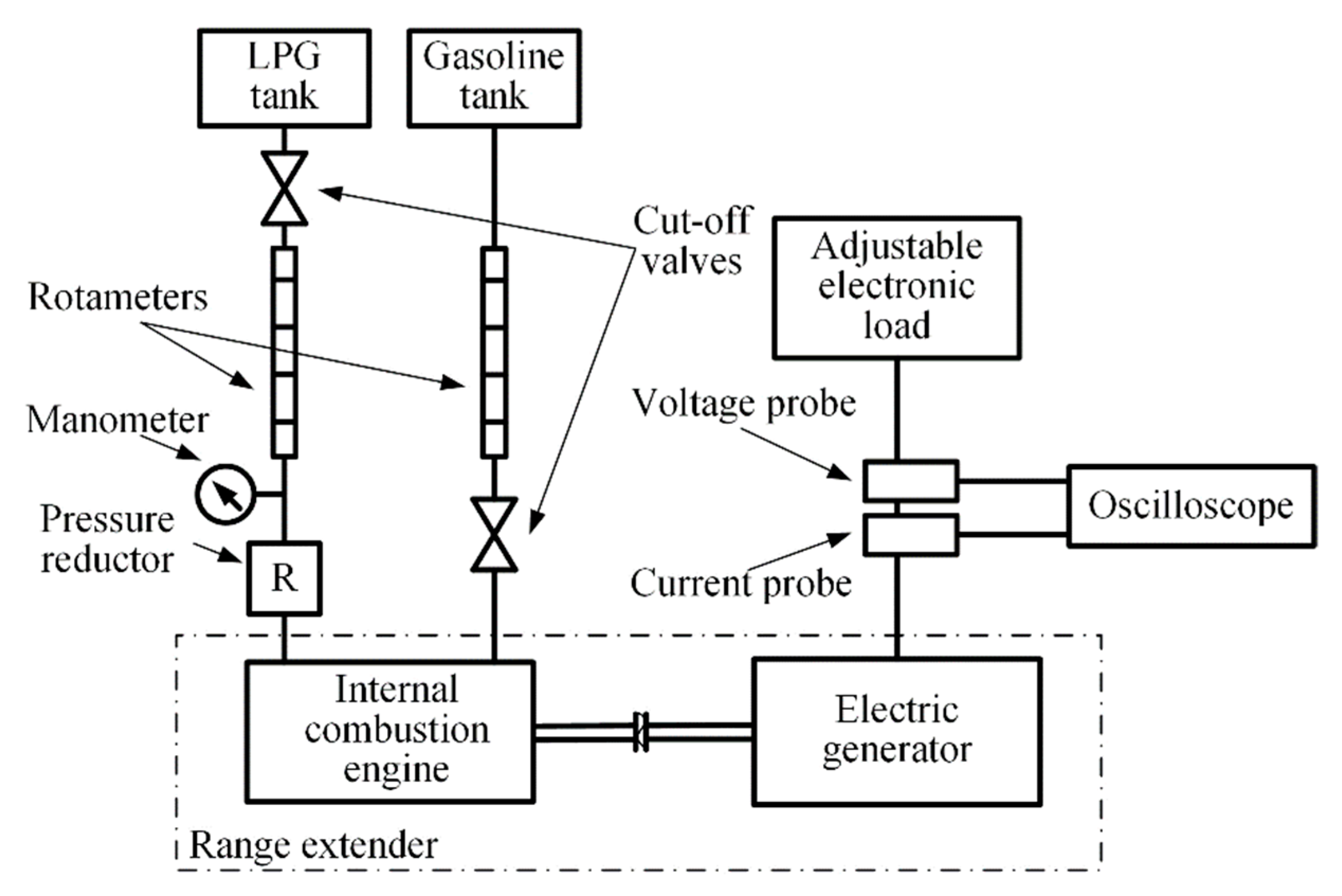
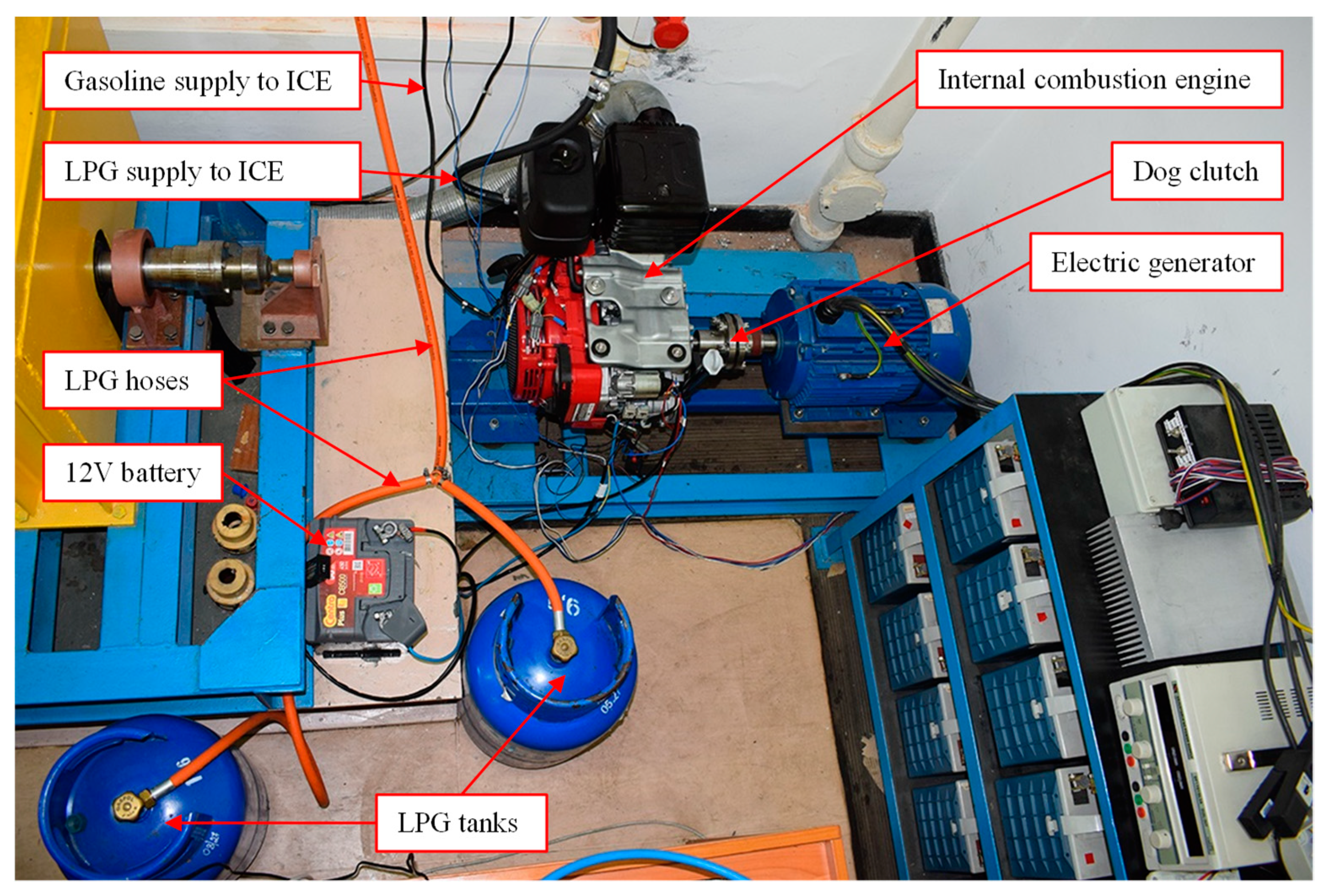
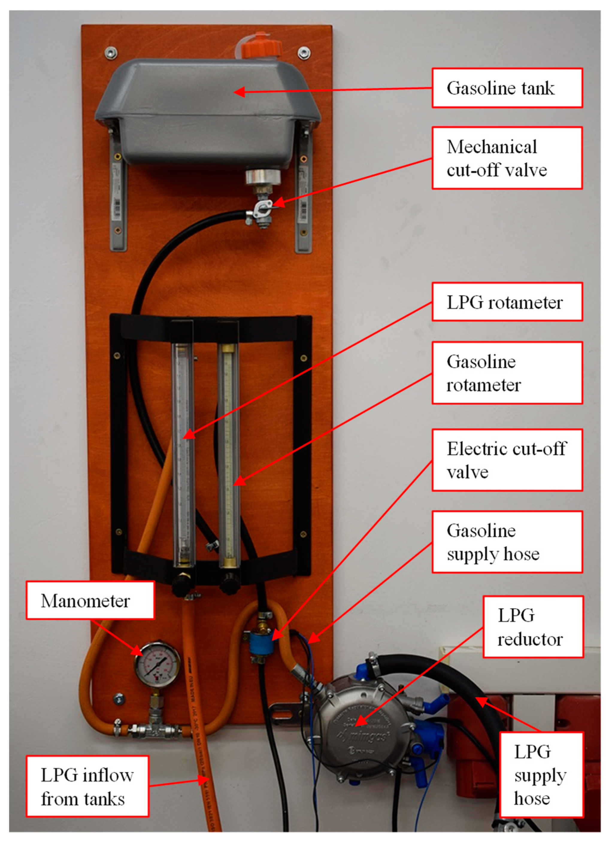
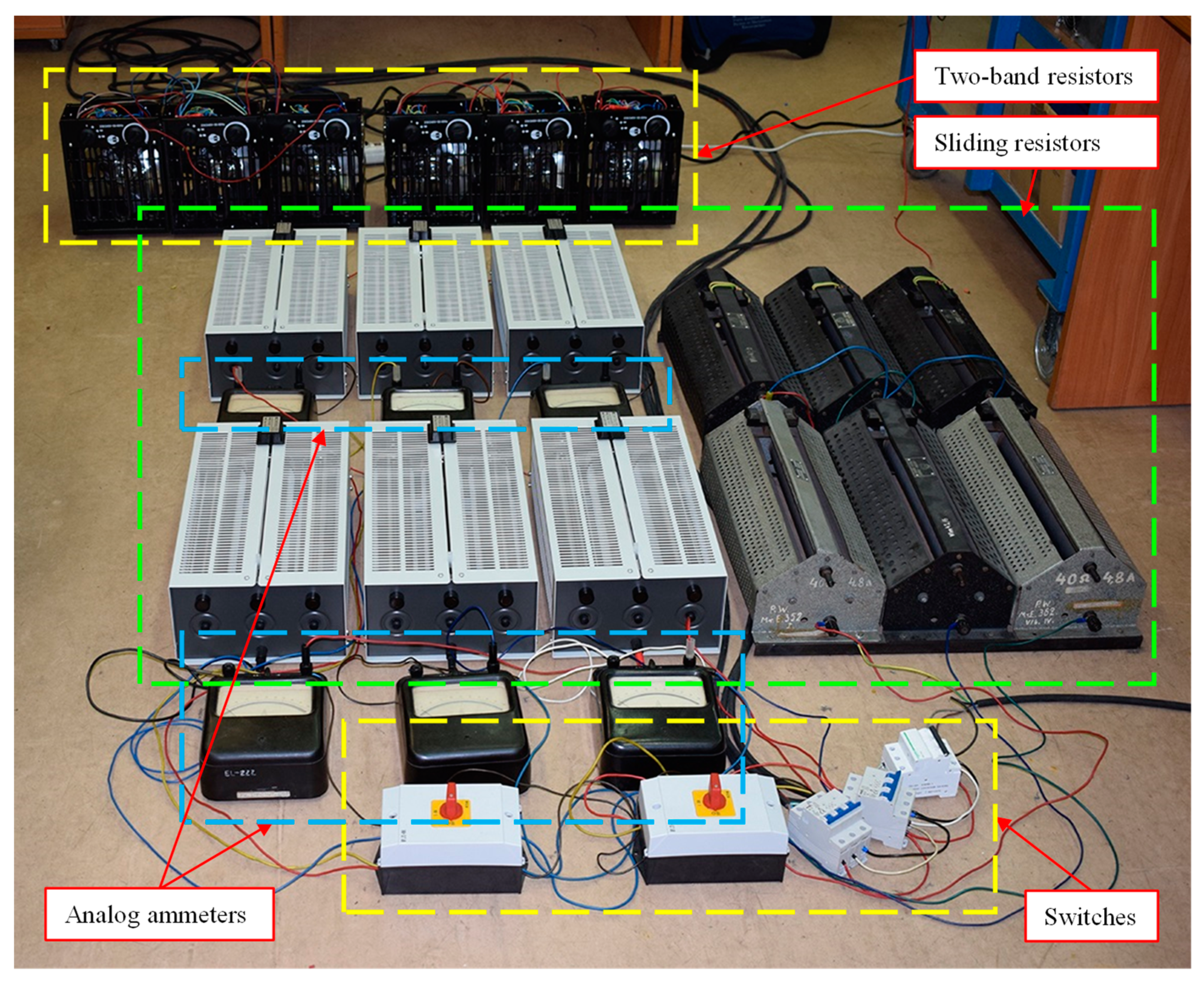
2.1. Laboratory Test Stand

The general concept of the laboratory test stand which was built to conduct experimental work is shown schematically in Figure 2. The main element of the test stand was a range extender, consisting of a four-stroke, spark-ignited, single-cylinder engine Honda IGX440 (specifications given in Table 1), coupled with an electric generator KOMEL PMGgi132M4C (specifications given in Table 2) through dog clutch. The ICE had two separate fuel supply systems dedicated to LPG and gasoline. LPG was stored in liquid state in two portable gas cylinder containers and supplied to the ICE in gaseous state. It was possible to use both containers simultaneously or only one at the time. The tank with gasoline was attached to the wall above the ICE and was equipped with a cut-off valve and a fuel filter. The outflow of gasoline from the tank was assisted by gravity. The fuel flow rates were measured using two rotameters manufactured by ROTAMETR: type RTU-06-300 for gasoline (measuring range 0.2–4.2 dm3/h) and type RTU-10-300 for LPG in the gas phase (measuring range 0.01–1.2 m3/h). LPG pressure in the gas phase was measured with a manometer having the range of 0–25 bar. The manometer was placed between the rotameter and the pressure reducer. Engine rotational speed was measured using a mobile meter with an optical transducer.
The electric generator was connected to an energy dissipation system with adjustable resistance. The system consisted of 18 resistors (12 sliding resistors and six two-band resistors). Resistors were divided into five sections, which could be independently switched on and off if necessary. Each resistor (or a set of resistors) was interfacially connected in the delta arrangement. The sections were connected in parallel between each other, so the same voltage could be obtained on each connected set of resistors. The energy dissipation system was always loaded symmetrically, which meant that the current on each of the three phases of the generator was adjusted with the aid of slide resistors. The measurement of the electric current on the slide resistors was provided by six analog ammeters. Phase current and line voltage were measured with the current probe and the voltage probe, respectively. Signal recording was carried out using a digital oscilloscope.
Figure 3, Figure 4 and Figure 5 show photos of the actual laboratory test stand used in the empirical work.

2.2. Fuels

Commercial gasoline and commercial LPG available at a large chain of filling stations in Poland were used to supply the ICE of the range extender. Selected parameters of these fuels are listed in Table 3 and Table 4, respectively.

2.3. Experimental Procedure

Working points of the range extender, at which the measurements were carried out, were defined in coordinates of rotational speed and load (torque). They were selected in such a way as to uniformly cover the entire working area of range extender, limited by the nominal external speed characteristic of the ICE. Namely, the following ranges were adopted: rotational speed 1400–3600 min−1, with 200 min−1 step and load (torque) 4–26 Nm, with 2 Nm step. During the tests, the initial number of working points was reduced, taking into account actual shape of the external characteristic of the ICE. Finally, measurements were made at 121 points for LPG and at 128 points for gasoline.
The experimental procedure began with setting the required rotational speed and load (torque) values for a given measuring point. The electrical load at the energy dissipation system was adjusted so that the range extender was loaded with appropriate torque. Since the voltage of the electric generator depends on the rotational speed of the ICE, each time the appropriate load was set, it was followed with verification and, if necessary, adjustment of the rotational speed. In particular, to determine the maximum loads at a given rotational speed, this process had to be repeated several times. As soon as the ICE’s working point was reached, the fuel flow rate was measured. In addition, LPG flow rate reading was corrected for the actual LPG pressure.

2.4. Data Postprocessing

The data collected from the range extender were analyzed to generate BSFC, thermal efficiency, and CO2 emission maps. In order to calculate the efficiency of the range extender at each working point, the calorific value and density of fuels had to be considered. The following values were then assumed: 45.6 MJ/kg and 1.97 kg/m3 for LPG (gaseous state, 1 bar), 43.0 MJ/kg and 747.5 kg/m3 for gasoline. CO2 emission was determined by applying emission factors from literature [37]: 3030 gCO2/kgLPG and 3180 gCO2/kggasoline. The graphical representation of the results, e.g., maps with isolines for BSFC, thermal efficiency, and CO2 emission, was developed in MATLAB® software using the algorithm included in the Appendix A.

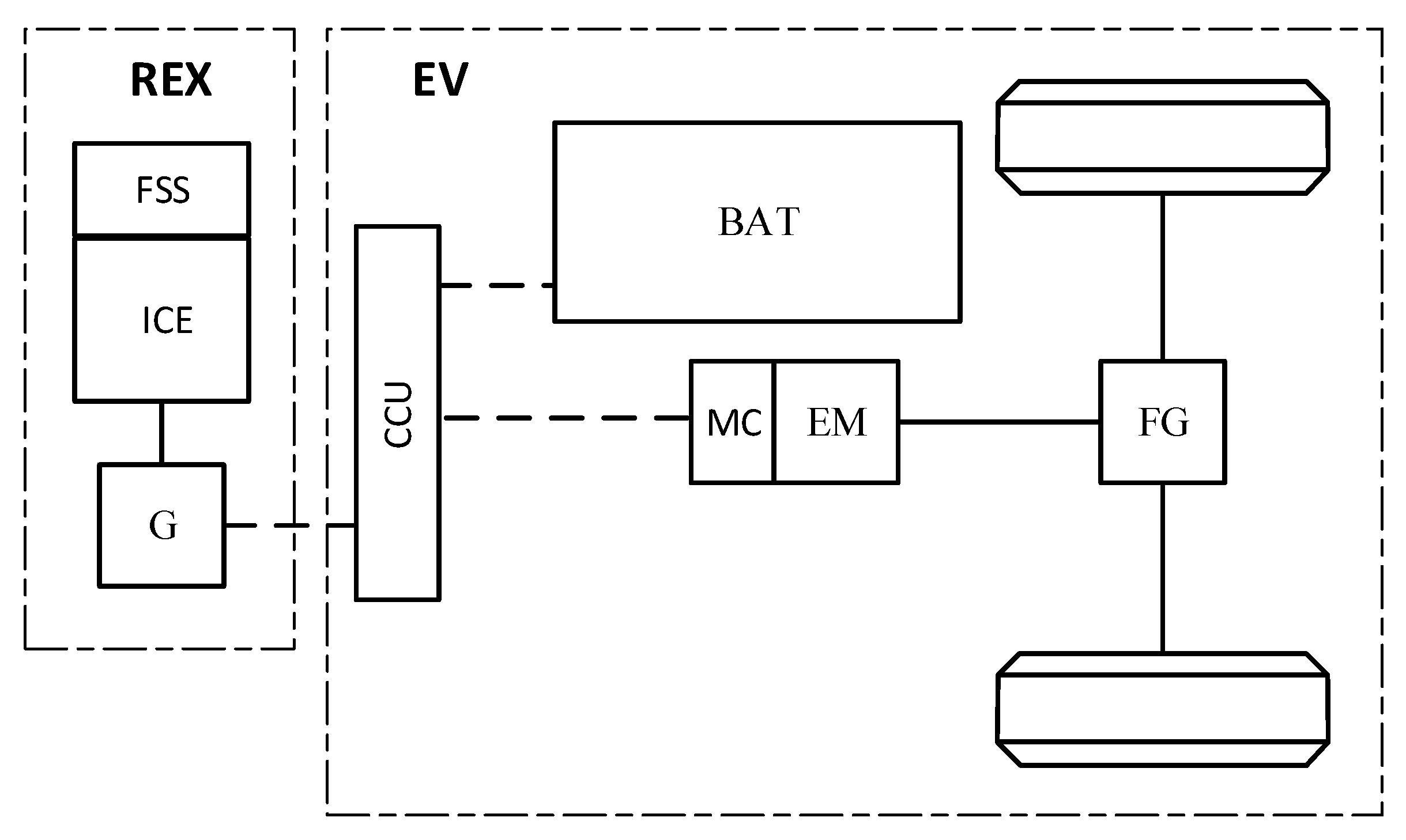
2.5. EREV Simulation

Simulation was performed to demonstrate the benefits of having a full BSFC map of the range extender. It was based on methods shown in [11] and included two control strategy variants applied to the LPG-supplied range extender. The vehicle in mind is a subcompact car with a lithium-ion battery. The battery operation state of charge (SOC) is narrowed to a range between 90% (charged) and 15% (discharged) for battery longevity [38]. Driving cycle selected is made from the first three stages of Worldwide harmonized Light vehicles Test Cycle 3b (WLTC 3b), which represents city and rural driving.
The LPG-supplied range extender’s power delivery control is based on the traction battery SOC value. Knowing the calculated battery SOC during the drive and calculated target battery SOC, the error value between the two at any given moment is also calculated. The applied range extender control strategy sets momentary values of range extender torque and rotational speed using two proportional-integral (PI) controllers working independently. Target SOC is setpoint, while battery SOC is process variable, and the goal is to minimize error between the two. By setting different values of proportional and integral constants of two range extender controllers, the slope of torque as a function of rotational speed can be adjusted, therefore changing the range extender’s operating points. To show the difference between the cases of knowing and not knowing the range extender maps, two variants of the control strategy were implemented, hereafter called strategy 1 (first strategy) and strategy 2 (second strategy). The differentiating factors between strategy 1 and strategy 2 are the values of the rotational speed and torque PI controller’s constants as well as low torque limit of the range extender. The PI controller’s constants were adjusted and the low torque limit set higher in strategy 1, the goal being for the range extender to be used in areas of lower BSFC and CO2 emission, and higher thermal efficiency. When momentary values of torque and rotational speed are calculated, momentary values of BSFC, thermal efficiency or CO2 emission are read directly from maps via lookup tables and integrated into the vehicle model. For both strategies, the resultant battery SOC during the cycle follows the same target SOC. The target SOC value changes from 90% at the beginning of the drive to 15% at the end, which is at the target diving range distance, and target function SOC over the travelled distance is a straight line with negative slope. The target driving range in this study was set to 200 km, which extends the pure battery driving range from 40 km.
Vehicle data is presented in Table 5. The vehicle model was made in MATLAB Simulink® software. The simulation model consists of subsystems representing the physical properties of the vehicle body and drivetrain, traction motor, traction battery, and range extender. The vehicle speed PI controller, based on the difference between cycle speed and simulated momentary speed, governs motor supply voltage, which is a control variable. A DC motor model is used to calculate the motor shaft rotational speed and torque along with the required supply voltage and current. The obtained momentary vehicle speed is used to calculate resistance forces: rolling, aerodynamic, and inertia. The traction motor is supplied from the battery and the range extender. The vehicle can recuperate kinetic energy to the battery during braking. The model is solved using the fixed step ordinary differential equation (ODE) solving method, with step size of 0.01. Extensive detail on modeling and simulation of this powertrain structure and its subsystems, including the lithium-ion battery, is presented by authors in [11].

3. Results and Discussion

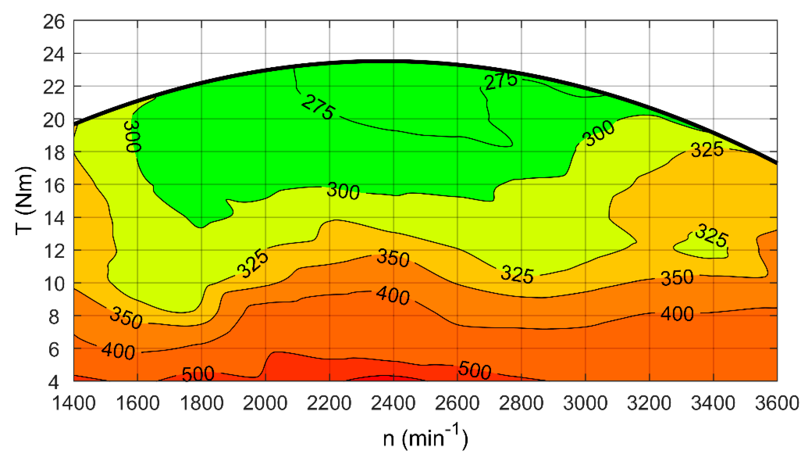
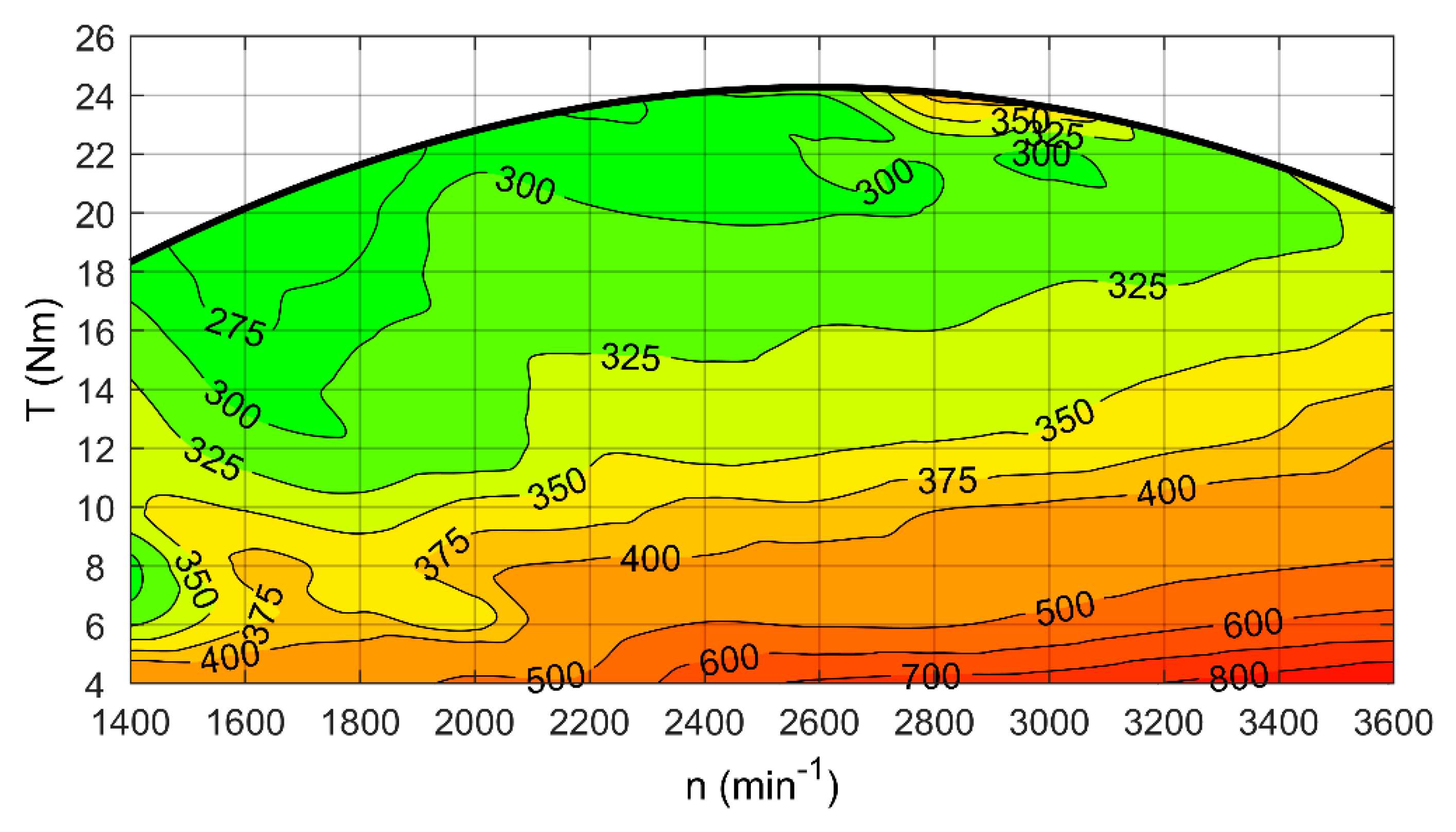
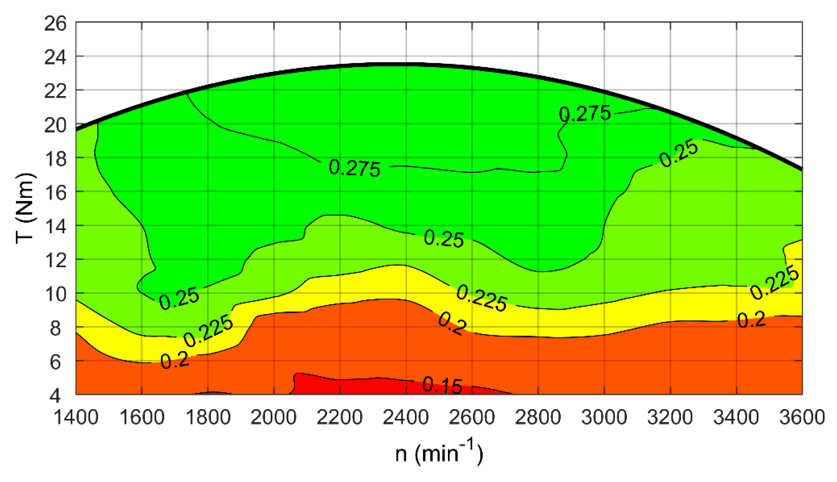
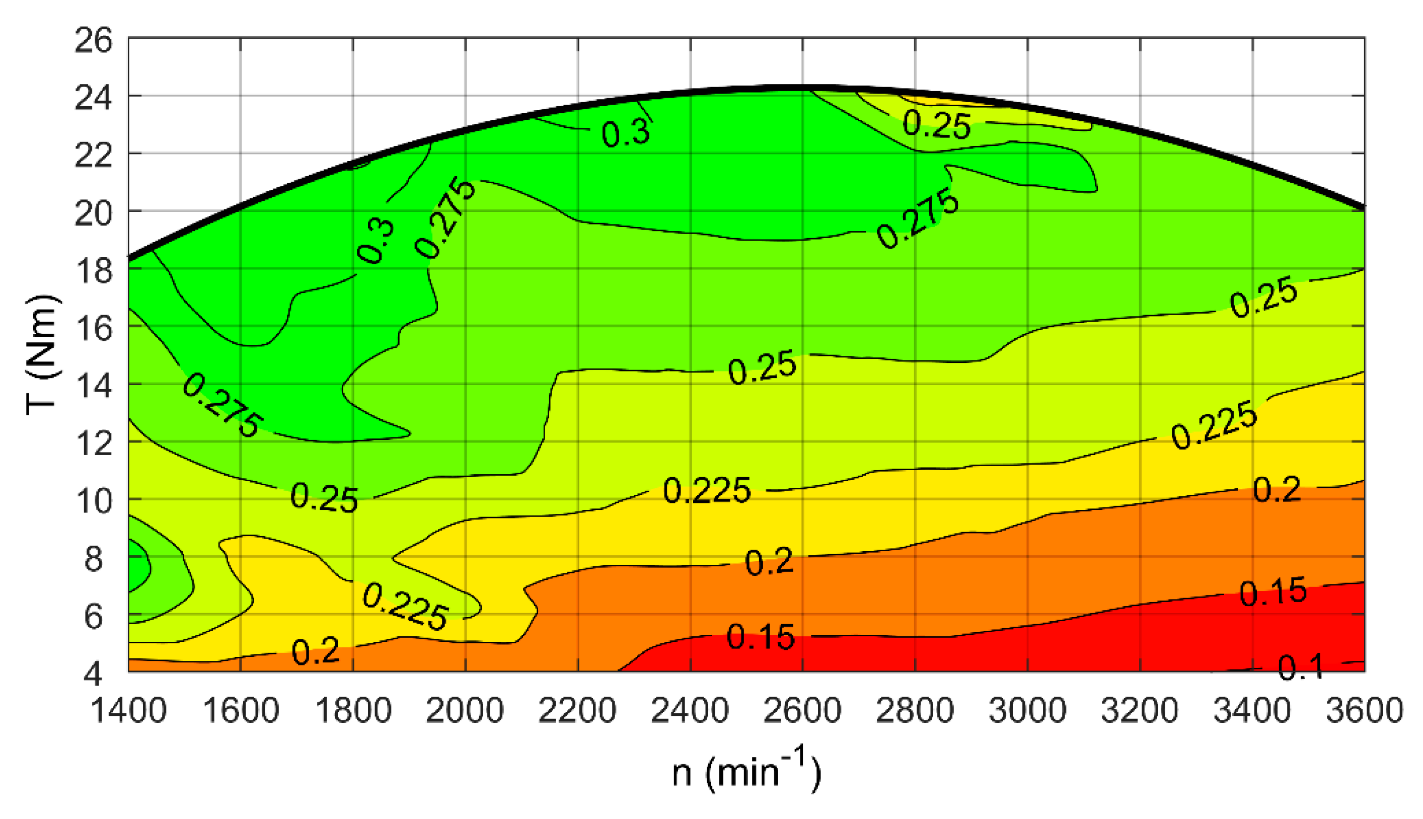
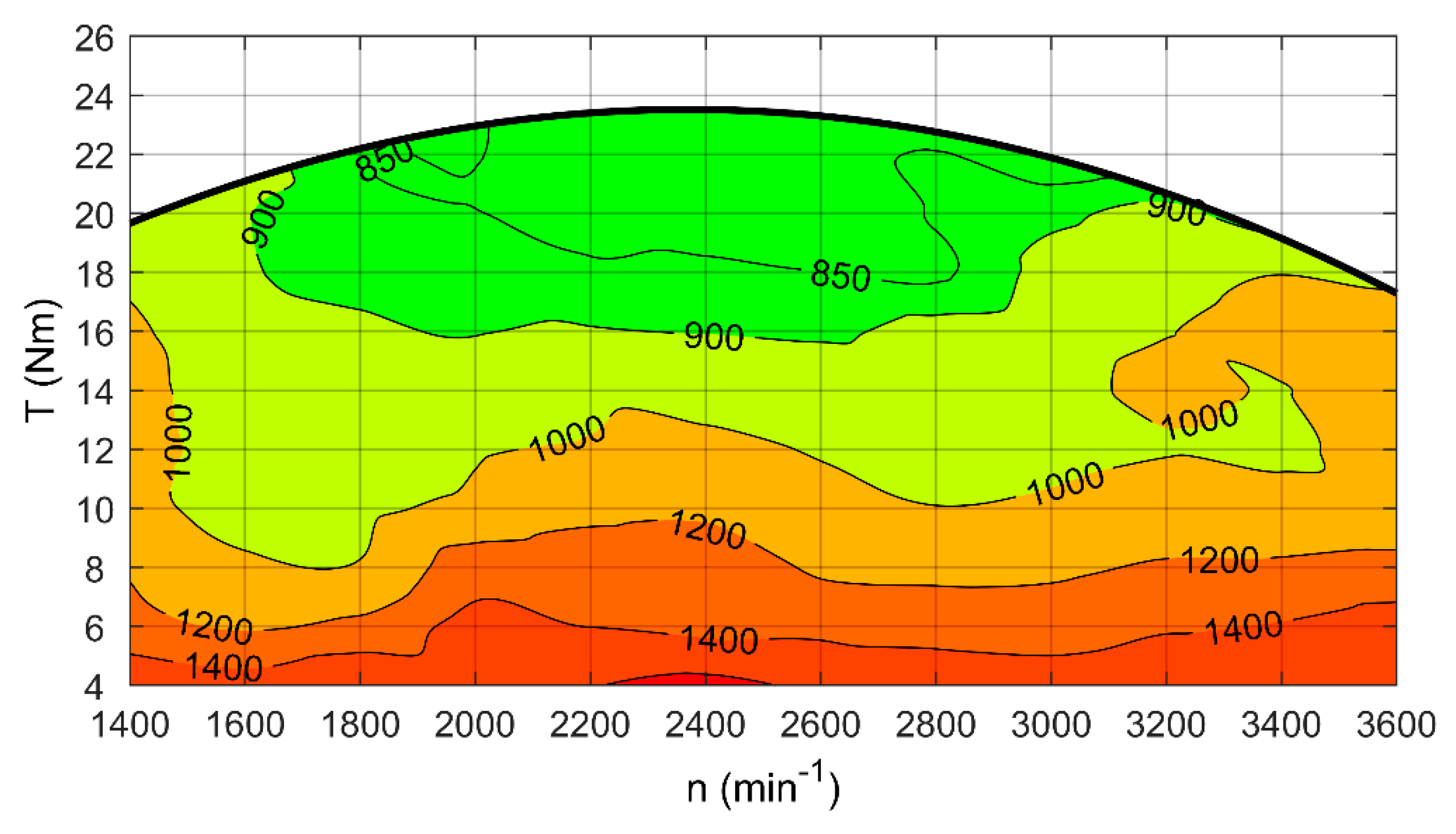
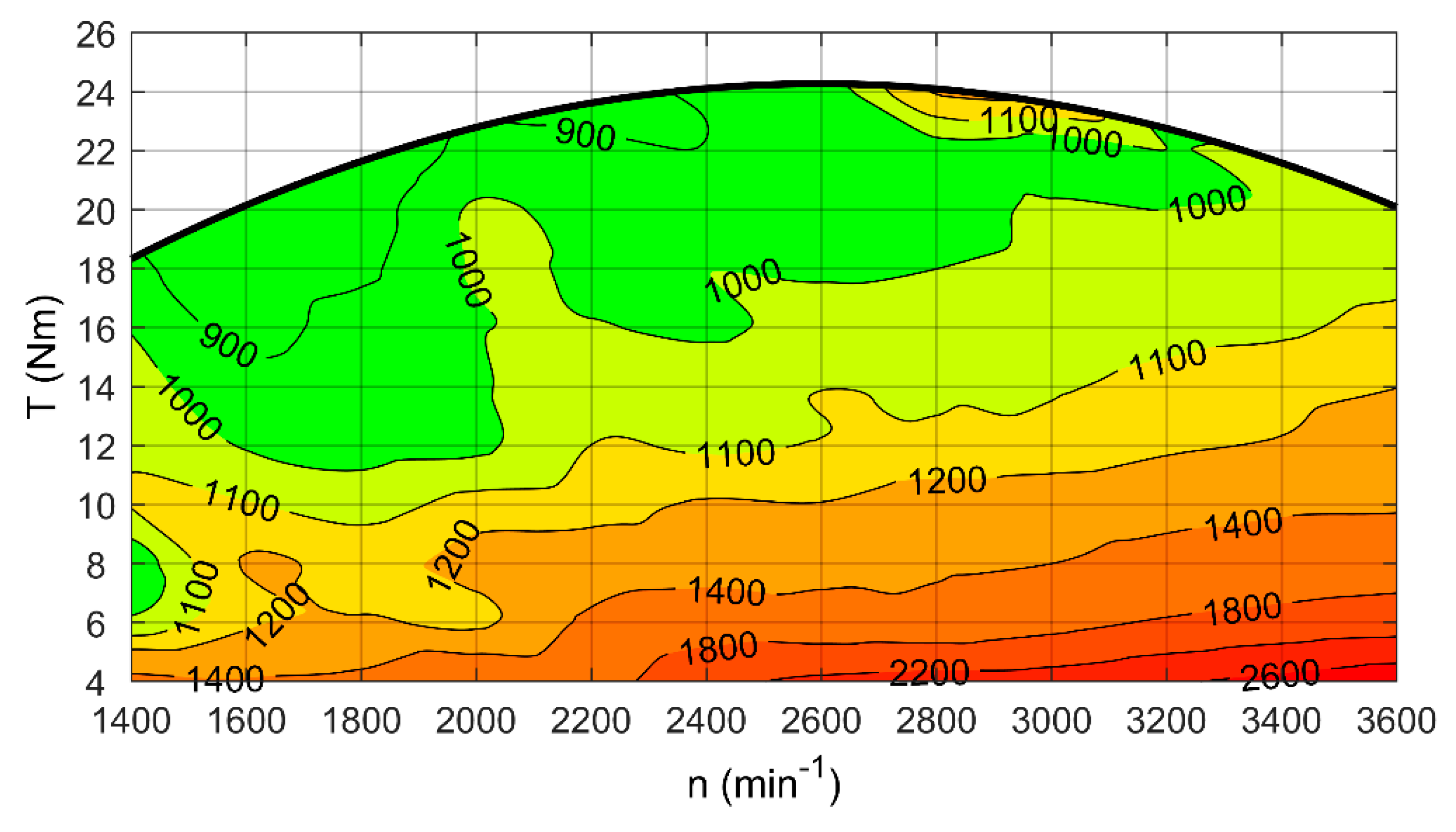
3.1. BSFC, Thermal Efficiency and CO2 Emission of the Range Extender

This section concerns the obtained BSFC, thermal efficiency, and CO2 emission maps and highlights some of the notable observations from the range extender testing. Appendix B contains more detailed results in tabular form.
Figure 6 and Figure 7 show BSFC maps generated from test data for the range extender when running on LPG and gasoline, respectively. In general, the shapes of the external characteristics of the engine supplied with each fuel show good agreement. It can be noticed that in the case of LPG, the profile has less curvature than that of gasoline. The torque maxima differ slightly and occur at different rotational speeds: 23.7 Nm at 2200 min−1 was obtained when supplying the range extender with LPG, while 24.5 Nm at 2600 min−1 was achieved with gasoline. Comparing the BSFC values over the entire map area, there is a disadvantage of gasoline. More gasoline than LPG, in terms of mass, is needed to obtain the same power of the range extender, but it is compensated by the higher calorific value of LPG. The lowest values of BSFC obtained are similar: around 258 g/kWh for gasoline and 264 g/kWh for LPG. However, they occur in different regions of the map. In the case of LPG, low BSFC occurs at high load, more or less between the rotational speed of 2100–2700 min−1, and for gasoline, it appears also at high load but is shifted towards low rotational speed, around 1500–1900 min−1. Finally, the map generated for the LPG-supplied range extender is characterized by greater homogeneity than for gasoline, i.e., the isolines are distributed more evenly and have less local changes.
BSFC obviously correlates with the thermal efficiency of the range extender, as shown in Figure 8 and Figure 9. Low BSFC corresponds to high thermal efficiency and vice versa. The highest efficiency for an LPG-supplied range extender is 29.9%, while for gasoline it is 32.4%. The difference of 2–3% in favor of gasoline can be explained by the fact that the ICE used in the range extender was factory-fitted for the combustion of gasoline, while the LPG supply system was installed additionally. Minor differences in the positioning of isolines on the map result from the adopted ranges of values into which the results were divided when generating the map. This draws attention to the problem of the methodology of map generation. Having the same set of data, but using different algorithms, several maps can be obtained [32]. For this reason, it is important to analyze the exact values of parameters determined during empirical research (Appendix B).
CO2 emission related to the work performed by the range extender was determined to compare the environmental effects of using both fuels. When comparing the results, it can be concluded that LPG (Figure 10) has an advantage over gasoline (Figure 11) according to this criterion. CO2 emission values are approximately 100 g/kWh lower for the LPG supply than for gasoline within the high load regions of the map, while at low load and high rotational speed, this difference increases to around 200 g/kWh, and in extreme cases even up to 1400 g/kWh. This observation can be useful for optimizing the range extender control due to the minimization of CO2 emission and at the same time confirms the advantages of using LPG as fuel for EREVs.

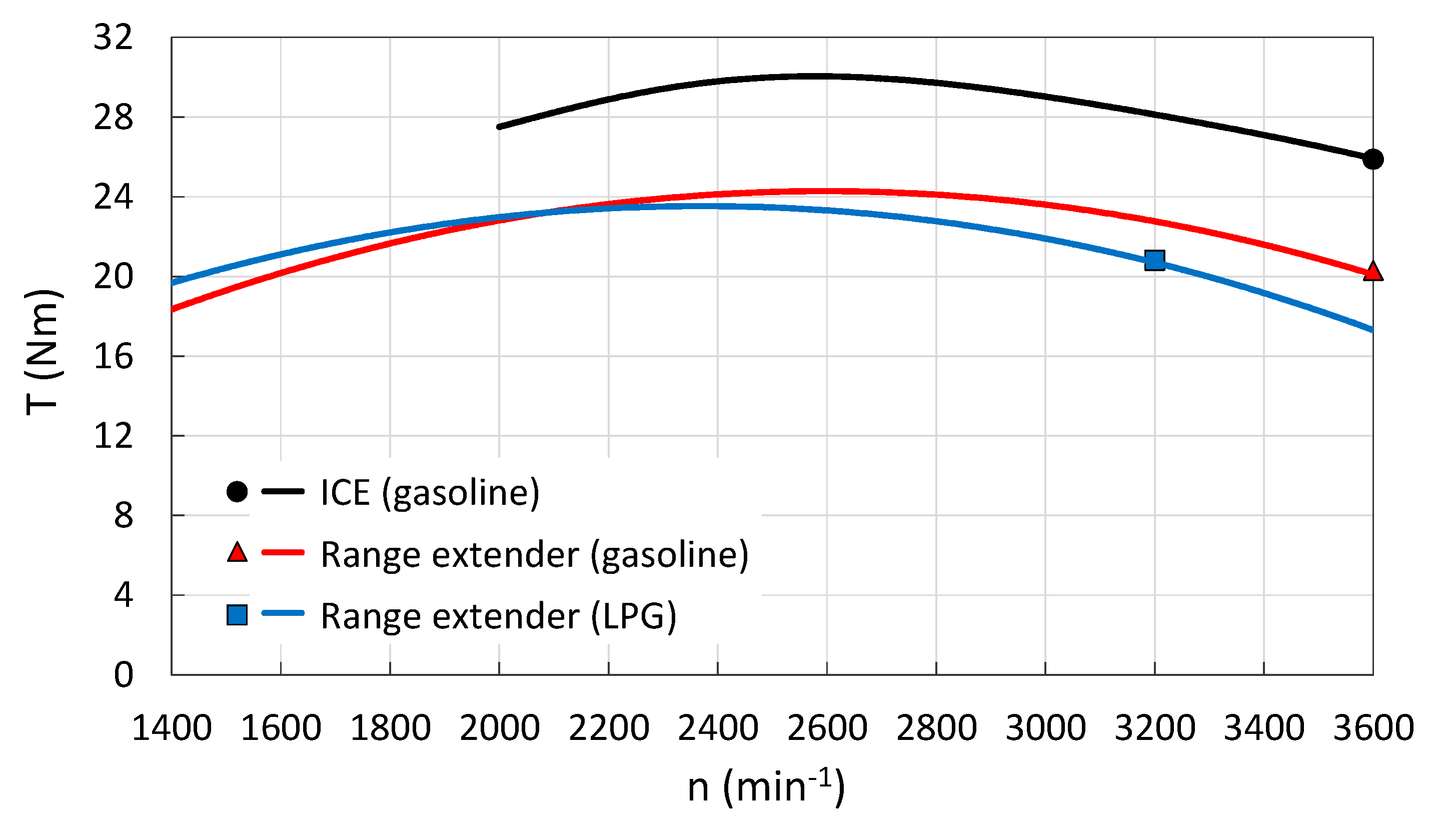
3.2. Comparison with ICE Characteristics

In order to give a reference to the test results presented above, they have been compared with relevant ICE characteristics as claimed by the manufacturer. Obviously, a direct comparison is not possible, since the range extender characteristics result from combining the characteristics of both the ICE and the electric generator. Furthermore, data provided by the ICE manufacturer is limited to the torque curve at full load for the recommended operating speed range of 2000–3600 min−1 and fuel consumption rate for a single operating point [39]. Nevertheless, as this is the closest available reference that can facilitate the assessment of the experimental results, it is discussed further in this section.
Figure 12 compares full-load torque curves for the ICE supplied with gasoline and the range extender supplied with gasoline/LPG. While the general shape of these curves can be evaluated as similar, especially for gasoline, the curves for the range extender are shifted down compared to the curves for ICE. To be specific, the range extender torque is about 17–22% lower in the case of gasoline supply and about 17–32% for LPG supply. The difference in torque values increases with rotational speed.
Further conclusions can be drawn from the analysis of the ICE and range extender performance at selected operating points (Figure 12). The ICE manufacturer specifies the fuel consumption rate at the point of maximum power, which corresponds to a rotational speed of 3600 min−1. The criterion of maximum power was therefore adopted to select range extender operating points for comparison. It should be noted that for the gasoline-supplied range extender, the maximum power occurs at 3600 min−1, while that of the LPG-supplied range extender is at 3200 min−1. BSFC, thermal efficiency, and CO2 emission for these points are presented in Table 6.
Comparing data from Table 6, it can be clearly seen that the range extender is characterized by worse BSFC and thermal efficiency than the ICE itself. However, this is an easily predictable result, given the fact that the range extender’s performance has to include the efficiency of energy conversion by the electric generator and its own sensitivity to operating conditions (load, rotational speed, temperature, etc.). Importantly, the LPG-supplied range extender has lower CO2 emission than the gasoline-supplied ICE, with only slightly degraded BSFC and thermal efficiency values.

3.3. Comparison with Commercially Available Range Extenders

This section compares results obtained in this study with the performance of commercial applications of range extenders. However, while the body of scientific literature on EREVs is growing, the availability of credible BSFC/efficiency maps of range extenders (ICE coupled with electric generator) is scarce. For obvious reasons, companies involved in the development of this technology are reluctant to or even refuse to publish such data. On the other hand, they usually provide BSFC at nominal operating point/points. This parameter was therefore chosen to compare the range extenders. In the case of the device tested in the laboratory as part of this study, the operating points listed in Table 6 were adopted. Thermal efficiency and CO2 unit emission have been calculated on the basis of BSFC according to the assumptions presented in Section 2.4. The results are shown in Table 7.
The range extender tested under this study has a rather high BSFC of 334 g/kWh and 288 g/kWh, for gasoline and LPG supply, respectively, compared to commercial devices achieving 230–260 g/kWh (except for BMW, but these are not official manufacturer data). However, the obtained results should be considered as satisfactory, given the laboratory nature of the tested device, intended for research purposes, and not for use in vehicles.

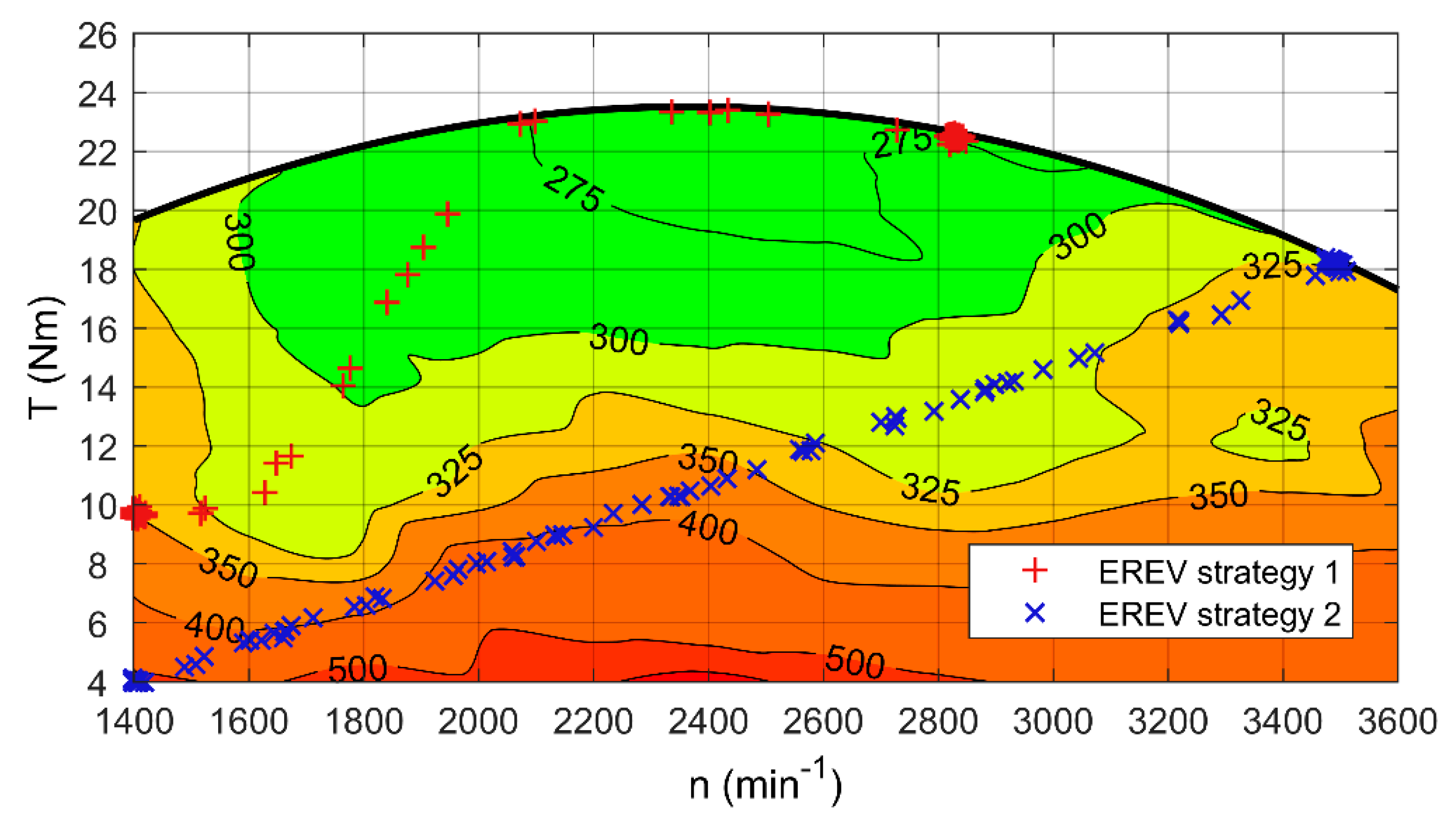
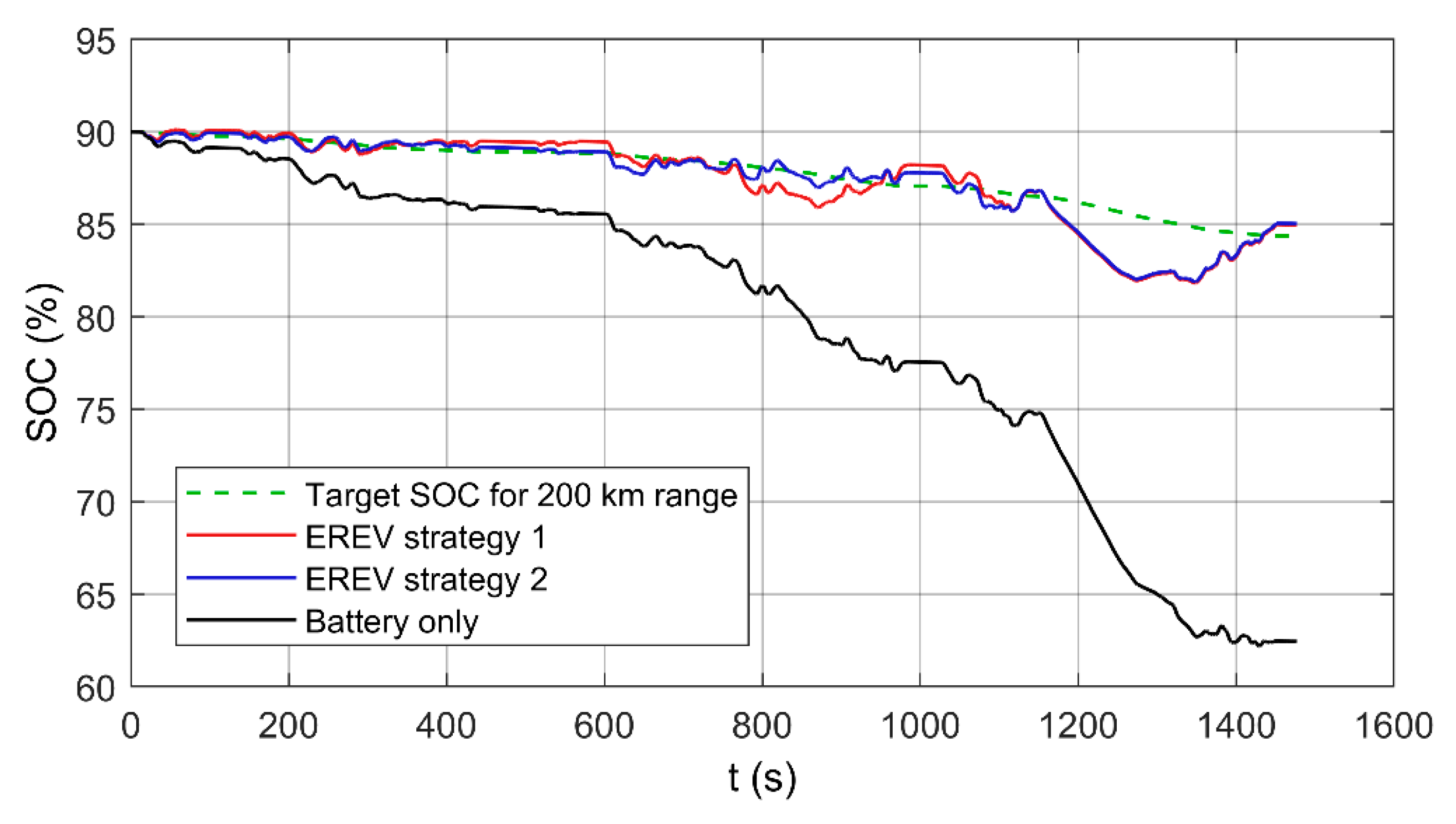
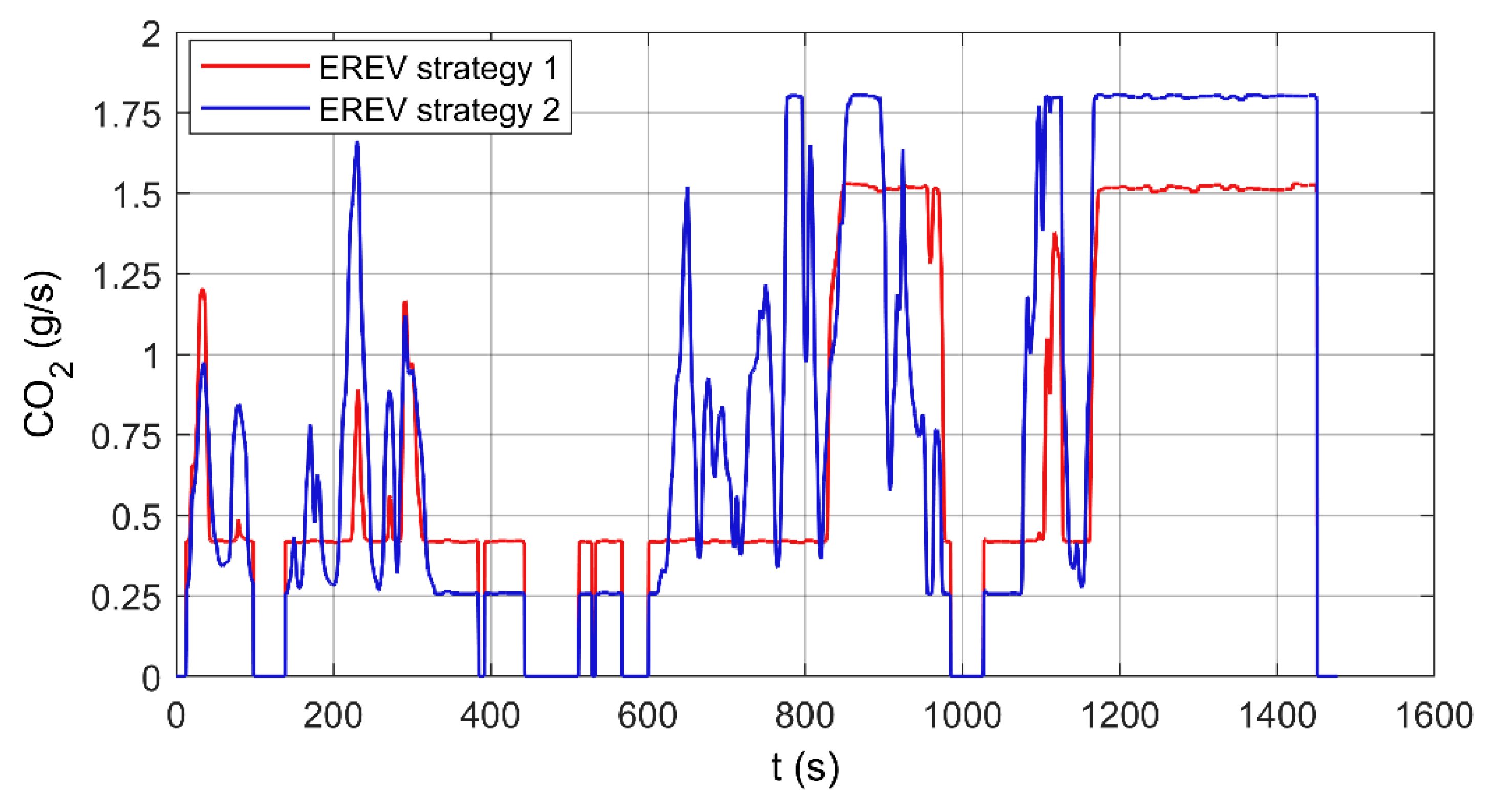
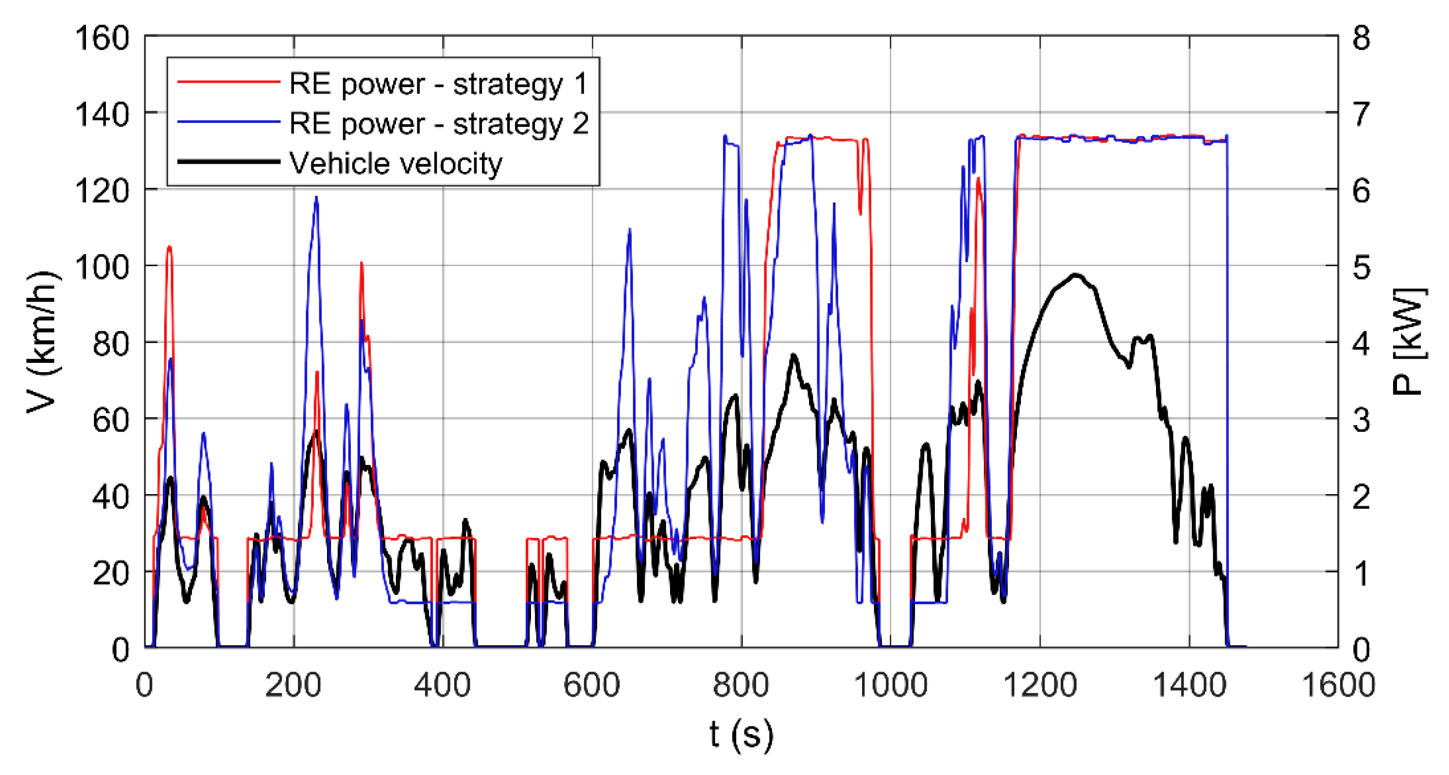
3.4. EREV Simulation in a Driving Cycle

Figure 13 shows LPG-supplied range extender operating points on the BSFC map. In the first strategy, the relation between range extender torque and rotational speed is partially linear. This strategy takes into account knowledge obtained by having the range extender’s BSFC. At low rotational speeds of the range extender, the low limit of torque delivery is set higher and the resultant power delivery is higher than for the second strategy. The transition from low to high torque in the first strategy is faster and takes path in the area of lower BFSC, compared to the second strategy. For high power demand, operating points of the range extender are limited by the maximal torque characteristic and therefore keeping the range extender operating points in the area of low BSFC. The second strategy represents the linear relation between the range extender’s rotational speed and torque. The trajectory of this strategy does not take into consideration the specificity of the BSFC values of the gathered data.
As shown in Figure 14, both strategies result in the same final SOC value after one cycle. Moreover, both strategies follow the target SOC line; therefore, the range extender will provide the desired range extension. In this aspect, both strategies of range extender control performed equally well, and the studied range extender was proven to be an adequate device for a simulated vehicle, potentially extending the vehicle range much beyond 200 km.
Figure 15 shows that CO2 emission intensity is considerably lower for first control strategy over majority of the driving cycle. This equates to CO2 road emission of 68.7 g/km and 80.5 g/km for the first and second control strategies, respectively. This is an important result considering the desirability of using EREVs as vehicles with limited environmental impact.
Both control strategies are set to provide the same maximal range extender power output. Figure 16 shows output power for two strategies along with the driving cycle. The main differentiating factor is the fuel consumption. The first strategy utilizes obtained knowledge of this particular range extender unit, made possible by conducting the presented empirical studies. The resultant LPG consumption is 2.27 kg/100 km (4.20 dm3/100 km). On the other hand, the second strategy results in LPG consumption of 2.66 kg/100 km (4.93 dm3/100 km), which is a 17.2% increase over the first strategy. When driven in the course of one cycle (15.01 km), the EV would consume 1.40 kWh (5.04 MJ) energy from the battery. In the same conditions, the EREV consumed 0.25 kWh (0.9 MJ) energy from the battery, the same amount for both control strategies. However, for the first strategy, the energy of consumed LPG equates to 15.54 MJ per cycle, while for the second strategy 18.21 MJ per cycle. The total energy consumption is 16.44 MJ and 19.11 MJ per cycle, respectively. It means an overall 16.2% difference in favor of the first strategy.
This simulation study shows the importance of having the range extender BSFC and emission maps. This data provides vital insight to range extender behavior and EREV performance. To properly tailor the control strategy of the range extender, its operating points in the whole spectrum of rotational speed and torque are necessary. The resultant dataset was easily implemented to MATLAB® software, and then passed to an existing vehicle simulation model in Simulink®. Such a dataset provides a starting point for developing more advanced control strategies and this study was made to preliminarily show the potential of utilizing the empirical studies presented in this paper.

3.5. Limitations of the Study

As with any empirical study, the results presented in this paper are subject to certain limitations, which suggest future research directions.
Firstly, one should keep in mind the properties of the test object, i.e., the range extender, when interpreting the results. In particular, the design and regulation of the ICE fuel systems influence the obtained results. In order to avoid tampering with the factory settings, the gasoline supply system and its control were left unchanged. In contrast, the fitted LPG supply system was very simple, had some limited regulation possibilities, and could be easily adapted to the working conditions. It consisted of a pressure reducer and a nozzle mounted in the inlet manifold of the ICE, introducing LPG in a gaseous form. The systems with liquid LPG injection offer greater control possibilities, but on the other hand, the simple system seems to be a better option in the case of the range extender, which in principle is intended to be activated rarely and for short time periods. Nevertheless, for the study presented in this paper, the LPG supply system’s regulation was set initially and no regulatory changes were made during measurements.
Secondly, no measurements have been made for the low range of range extender torque. This was due to the difficulty of obtaining low electrical load values. ICE idling fuel consumption is certainly an important piece of information for future research involving simulation of the range extender work.
Thirdly, CO2 emission has been determined indirectly, i.e., based on BSFC knowledge and with the use of emission factors related to fuel mass. An interesting direction of future research would be to measure the concentration of pollutants in the ICE exhaust, taking into account not only CO2, but also other substances.
Fourthly, when developing the empirical research plan, a gridded map of range extender working area was applied, as it is desirable to simplify the interpolation of results for simulation. As a consequence, the data obtained is gridded naturally by the test method with consistent rotational speed and torque values. For a better resolution of results, it would be worth considering the compaction of the grid, at least to the intervals of 100 min−1 for the rotational speed and 1 Nm for the torque. Another solution would be the use of the cluster method [30], in which the grid of measurement points is constructed by splitting the set of speed and torque data into several groups (clusters) in such a way that the points in the same group are more similar according to the chosen criteria to each other than to those in other groups.
Moreover, the maps presented in this paper have been generated using our own interpolation algorithm for measurement results obtained at a limited number of points. However, to be able to quantify precise BSFC, efficiency, and CO2 emission values in other points between those selected for measurements, other methods can be used [32]. Further work would be needed to explore this subject and to obtain an unbiased assessment of the used interpolation algorithm.

4. Conclusions

This paper presents and discusses BSFC, thermal efficiency, and CO2 emission maps developed from testing of a range extender supplied with LPG and gasoline. The empirical data collected has been adopted in the simulation of EREV performance in a driving cycle, demonstrating the benefits of the proposed approach.
The analysis of the study results allows us to conclude that BSFC and thermal efficiency of the LPG-supplied range extender are at a comparable level to the case of gasoline supply, but with less CO2 emission. There is still potential for further improvements through application of technologies already existing in modern automotive ICEs and the use of alternative fuels.
Future studies should focus on developing maps separately for the ICE and for the electric generator, and then comparing their mathematical synthesis with the map obtained empirically for the entire range extender. This would give the basis for verification of the effectiveness of such "combined maps" for simulation purposes of EREVs, and facilitate the selection of ICE and generator when constructing a range extender.
The main area of application of the presented data are simulation studies of HEVs and EREVs. The obtained maps are of great significance for research works aimed at developing and analyzing various EREV control strategies. In addition, this study provides much needed data for examination and comparison of different architectural solutions of vehicle powertrains in terms of performance, revealing potential benefits, limitations, and challenges.
From the automotive industry perspective, the availability of complete, well documented empirical data is essential to accelerate the development of new generation range extenders, which are able to meet increasingly stringent pollutant emission and fuel consumption requirements. Comparison of the various range extender concepts available on the market today indicates that the main benefits of an LPG-supplied range extender are low operating costs and low CO2 emission. It can be a feasible solution for diversification of fuel mix in transportation, particularly in countries with well-developed infrastructure of LPG refueling stations, where original equipment manufacturer vehicles, i.e., having an LPG system fitted at the factory on the new vehicle, have already been offered.

Author Contributions

Conceptualization, J.L. and A.K.; methodology, J.L., A.K., P.K. and P.R.; software, P.K.; validation, J.L., P.K. and P.R.; formal analysis, P.K.; investigation, J.L., A.K., P.K and P.R.; resources, P.R.; data curation, P.K.; writing—original draft preparation, J.L.; writing—review and editing, P.K. and A.K.; visualization, J.L., P.K.; supervision, A.K.; project administration, A.K.; funding acquisition, A.K. and P.K.

Funding

The APC was funded by the Faculty of Automotive and Construction Machinery Engineering at the Warsaw University of Technology.

Conflicts of Interest

The authors declare no conflict of interest.

Appendix A

The algorithm of approximation of test results used to generate maps in MATLAB® software.
%% MATLAB® code procedure for plotting range extender maps. %%
% Clear variables and command window %
clear all
clc
% Load efficiency table data matrix (MxN) for fixed step changing values % of torque (M) and speed (N) as presented in the paper, but without values at % torque limits.
load Data_Eff.mat;
% Get efficiency values at torque limits for each speed
% and maximal torque values for each speed, which are not in fixed increments.
At_Limits_Data_Eff = [0.292 0.321 0.324 0.294 0.309 0.272 0.272 0.225 0.228 0.275 0.260 0.250];
Limits_Torque_Vals = [18.4 20.2 21.4 22.8 23.8 24.2 24.5 23.8 23.7 22.8 21.3 20.3];
% Vectors 'Torque' and 'Speed' are corresponding to the measurements in fixed % increments. Inputs for further data processing are prepared. To interpolate % data between measurement points for plotting Resolution_Factor was set above % 1.
Resolution_Factor=100;
Torque=4:2:26;
Torque_Min=min(Torque);
Torque_Max=max(Torque);
Torque_Res=Torque(1,2)-Torque(1,1);
Torque_Interp_Step=Torque_Res/Resolution_Factor;
Speed=1400:200:3600;
Speed_Min=min(Speed(1,:));
Speed_Max=max(Speed(1,:));
Speed_Res=Speed(1,2)-Speed(1,1);
Speed_Interp_Step=Speed_Res/Resolution_Factor;
% Issue of non-fixed increments of torque values at the torque limits was % resolved by linearly extrapolating the data to next possible integer torque % value from the 'Torque' vector. For every speed (non-interpolated) largest   % fixed-increment 'Torque_Below_Limits' value was found, with M indexes     % 'Indexes_Limits' and the extrapolated values were assigned to 'Data_Eff' in % third for loop below.
for i=1:size(At_Limits_Data_Eff,2)
if mod(floor(Limits_Torque_Vals(1,i)),2) >0
Torque_Below_Limits(1,i) = floor(Limits_Torque_Vals(1,i))-1;
else
 Torque_Below_Limits(1,i) = floor(Limits_Torque_Vals(1,i));
end
end
for i=1:size(Data_Eff,2)
   for j=1:size(Data_Eff,1)
      if Data_Eff(j,i)>0
       Indexes_Limits(i)=j;
      end
   end
end
for i=1:size(Data_Eff,2)
  Data_Eff(Indexes_Limits(i)+1:size(Data_Eff,1),i) = Data_Eff(Indexes_Limits(i),i)+...
    ((At_Limits_Data_Eff(1,i)-Data_Eff(Indexes_Limits(i),i)).*(Torque_Res/(Limits_Torque_Vals(1,i)-Torque_Below_Limits(1,i))));
end
% Interpolated speed 'x' and torque 'y' were created along with grid
% coordinates 'xq' and 'yq'.
x=Speed_Min:Speed_Interp_Step:Speed_Max;
y=Torque_Min:Torque_Interp_Step:Torque_Max;
[xq,yq] = meshgrid(x,y);
% Grid data 'vq' used for plotting maps in the paper is created with
% triangulation-based cubic interpolation.
vq = griddata(Speed,Torque',Data_Eff,xq,yq,'cubic');
% Spare data above torque limits, given by polynomial M_Lim, was replaced
% with NaN values.
x_Lim_x=linspace(1,numel(x),numel(x));
x_Lim=(x_Lim_x-1).*Speed_Interp_Step+Speed_Min;
M_Lim=(((-0.000004153)*(x_Lim.^2))+((0.0215604396)*(x_Lim.^1))+((-3.6962537463)*(x_Lim.^0)));
M_Lim_x=(M_Lim-Torque_Min)./Torque_Interp_Step;
for i=1:numel(y)
   for j=1:numel(x)
     if i>M_Lim_x(j)
       vq(i,j)=NaN;
     end
   end
end
% Figure 'Map_Fuel_Eff_Fig' is created, with data plot as a contour plot % ('contourf' function) having isolines given by 'Levels' vector. Torque limit % is plotted also ('w1'). Other plotting options are used to set appropriate % axis labels, tics, tic labels, and some other minor graphical options are % also used. Final result is printed to .png file.
Map_Fuel_Eff_Fig=figure;
Levels=[0.05:0.05:0.2 0.225:0.025:0.325];
Labelx='n (min-1)';
Labely='T (Nm)';
[C,h]=contourf(vq,Levels,'-k');
hold on;
w1=plot(x_Lim_x,M_Lim_x,'-k','LineWidth',2.0,'MarkerEdgeColor','k','MarkerFaceColor','k','MarkerSize',2.0);
x_axis_scale=1;
y_axis_scale=1;
xtick=1:Resolution_Factor:numel(x);
xtick_labels=Speed_Min:Speed_Res*x_axis_scale:Speed_Max;
ytick=1:Resolution_Factor:numel(y);
ytick_labels=Torque_Min:Torque_Res*y_axis_scale:Torque_Max;
set(gca,'XTick',xtick,'XTickLabel',xtick_labels);
set(gca,'YTick',ytick,'YTickLabel',ytick_labels);
clabel(C,h);
T = [0 255 0; 128 255 0; 255 255 0; 255 128 0; 255, 0, 0]./255;
xc = [256; 192; 128; 64; 0];
map = interp1(xc/255,T,linspace(0,1,255));
colormap(map);
grid on;
paper_size_normal={0,0,6,3};
position_normal={0.12,0.16,0.8,0.82};
set(gcf,'color',[1,1,1]);
set(gcf, 'Visible', 'off');
set(gca,'box','on');
set(gca, 'Position', [position_normal{1,1}...
   position_normal{1,2} position_normal{1,3} position_normal{1,4}]);
ox=xlabel(Labelx,'FontSize',11,'Color','black');
oy=ylabel(Labely,'FontSize',11,'Color','black');
ax = gca;
ax.GridColor = [0.0, 0.0, 0.0];
ax.GridAlpha = 0.3;
set(gcf,'PaperUnits','inches','PaperPosition',[paper_size_normal{1,1}...
   paper_size_normal{1,2} paper_size_normal{1,3} paper_size_normal{1,4}]);
print(Map_Fuel_Eff_Fig,'Map_Fuel_Eff','-dpng','-r600');
		

Appendix B

The values of the parameters determined in the study of the range extender supplied with LPG/gasoline: brake specific fuel consumption (Table A1 and Table A2), thermal efficiency (Table A3 and Table A4), carbon dioxide emission (Table A5 and Table A6). Note that in the last rows of the tables, the values corresponding to the work points on the external characteristic are given, i.e., the highest possible torque (value in bracket) at a given rotational speed.
Table A1. Brake specific fuel consumption (g/kWh) of range extender supplied with LPG.
Torque
(Nm)
Rotational Speed (min−1)
140016001800200022002400260028003000320034003600
4518.81491.79538.03513.24590.23630.50568.28510.48492.63498.86473.18469.63
6417.72389.87411.53487.34460.76438.60440.63437.37434.55456.77464.76489.08
8389.70340.99335.00430.72443.77442.68386.54379.44382.86403.80405.38414.77
10344.57315.86319.05344.57375.90382.86348.48331.68339.77353.92359.75358.64
12341.84318.53304.11325.59334.95345.42325.93309.23319.32328.14319.68363.33
14338.37315.81298.26305.53322.99309.23309.74304.53315.81340.48328.95343.25
16336.69303.02299.28296.29298.43296.36294.61302.87310.04328.95343.25343.25
18324.94299.28292.63293.30282.96284.32280.94277.70303.64315.79328.95
20 298.21288.64280.98276.49270.93270.93281.95292.40303.64
22 280.73281.26268.69270.14270.14281.95
Max326.37303.23284.22282.01272.27265.81264.43268.27273.65288.13307.79326.90
(19.4)(21.2)(22.3)(23.1)(23.7)(23.5)(23.5)(22.6)(21.4)(20.8)(18.9)(17.7)
Table A2. Brake specific fuel consumption (g/kWh) of range extender supplied with gasoline.
Torque
(Nm)
Rotational Speed (min−1)
140016001800200022002400260028003000320034003600
4458.88446.13456.05517.51519.13654.33713.81739.30749.50803.04850.27902.18
6322.91371.78383.34368.80454.24505.62494.18492.87531.39579.97615.84641.11
8293.17379.21366.82392.60405.57408.95418.68427.01440.18474.01493.37510.57
10346.71347.98333.11356.90363.39380.70378.87397.69404.49414.90428.29432.25
12339.91312.29304.03309.32346.09342.03347.75352.66356.90371.78381.40403.17
14327.77293.17305.92311.02338.36339.91345.14342.34343.31353.72365.90376.73
16312.29273.26297.42312.29316.35308.57326.02325.04333.11337.39341.16356.90
18288.92267.68277.59317.25310.04313.94311.15314.42322.54322.21328.91334.87
20 258.76269.66317.65301.75297.42299.25300.82318.84314.52317.02333.61
22 292.01289.06283.90302.00303.60296.34314.32
24 294.94299.71
Max286.82261.17258.31284.64270.73308.06308.06371.95367.51304.57322.59334.32
(18.4)(20.2)(21.4)(22.8)(23.8)(24.2)(24.5)(23.8)(23.7)(22.8)(21.3)(20.3)
Table A3. Thermal efficiency of range extender supplied with LPG.
Torque
(Nm)
Rotational Speed (min−1)
140016001800200022002400260028003000320034003600
40.1520.1610.1470.1540.1340.1250.1390.1550.1600.1580.1670.168
60.1890.2020.1920.1620.1710.1800.1790.1810.1820.1730.1700.161
80.2030.2320.2360.1830.1780.1780.2040.2080.2060.1960.1950.190
100.2290.2500.2470.2290.2100.2060.2270.2380.2320.2230.2190.220
120.2310.2480.2600.2420.2360.2290.2420.2550.2470.2410.2470.217
140.2330.2500.2650.2580.2440.2550.2550.2590.2500.2320.2400.230
160.2340.2610.2640.2660.2650.2660.2680.2610.2550.2400.2300.230
180.2430.2640.2700.2690.2790.2780.2810.2840.2600.2500.240
20 0.2650.2740.2810.2860.2910.2910.2800.2700.260
22 0.2810.2810.2940.2920.2920.280
Max0.2420.2600.2780.2800.2900.2970.2990.2940.2880.2740.2570.242
(19.4)(21.2)(22.3)(23.1)(23.7)(23.5)(23.5)(22.6)(21.4)(20.8)(18.9)(17.7)
Table A4. Thermal efficiency of range extender supplied with gasoline.
Torque
(Nm)
Rotational Speed (min−1)
140016001800200022002400260028003000320034003600
40.1820.1880.1840.1620.1610.1280.1170.1130.1120.1040.0980.093
60.2590.2250.2180.2270.1840.1660.1690.1700.1580.1440.1360.131
80.2860.2210.2280.2130.2060.2050.2000.1960.1900.1770.1700.164
100.2410.2410.2510.2350.2300.2200.2210.2110.2070.2020.1950.194
120.2460.2680.2750.2710.2420.2450.2410.2370.2350.2250.2200.208
140.2550.2860.2740.2690.2470.2460.2430.2450.2440.2370.2290.222
160.2680.3060.2810.2680.2650.2710.2570.2580.2510.2480.2450.235
180.2900.3130.3020.2640.2700.2670.2690.2660.2600.2600.2550.250
20 0.3240.3100.2640.2770.2810.2800.2780.2630.2660.2640.251
22 0.2870.2900.2950.2770.2760.2830.266
24 0.2840.279
Max0.2920.3210.3240.2940.3090.2720.2720.2250.2280.2750.2600.250
(18.4)(20.2)(21.4)(22.8)(23.8)(24.2)(24.5)(23.8)(23.7)(22.8)(21.3)(20.3)
Table A5. CO2 emission (g/kWh) from range extender supplied with LPG.
Torque
(Nm)
Rotational Speed (min−1)
140016001800200022002400260028003000320034003600
41572.01490.11630.21555.11788.41910.41721.91546.81492.71511.61433.71423.0
61265.71181.31246.91476.61396.11329.01335.11325.21316.71384.01408.21481.9
81180.81033.21015.11305.11344.61341.31171.21149.71160.11223.51228.31256.7
101044.1957.1966.71044.11139.01160.11055.91005.01029.51072.41090.11086.7
121035.8965.2921.5986.51014.91046.6987.6937.0967.5994.3968.61100.9
141025.3956.9903.7925.8978.6937.0938.5922.7956.91031.7996.71040.0
161020.2918.2906.8897.8904.2898.0892.7917.7939.4996.71040.01040.0
18984.6906.8886.7888.7857.4861.5851.2841.4920.0956.8996.7
20 903.6874.6851.4837.8820.9820.9854.3886.0920.0
22 850.6852.2814.1818.5818.5854.3
Max988.9918.8861.2854.5825.0805.4801.2812.9829.2873.0932.6990.5
(19.4)(21.2)(22.3)(23.1)(23.7)(23.5)(23.5)(22.6)(21.4)(20.8)(18.9)(17.7)
Table A6. CO2 emission (g/kWh) from range extender supplied with gasoline.
Torque
(Nm)
Rotational Speed (min−1)
140016001800200022002400260028003000320034003600
41459.21418.71450.21645.71650.82080.82269.92351.02383.42553.72703.92868.9
61026.91182.21219.01172.81444.51607.91571.51567.31689.81844.31958.42038.7
8932.31205.91166.51248.51289.71300.51331.41357.91399.81507.41568.91623.6
101102.51106.61059.31135.01155.61210.61204.81264.71286.31319.41361.91374.6
121080.9993.1966.8983.61100.61087.71105.91121.41135.01182.21212.81282.1
141042.3932.3972.8989.01076.01080.91097.51088.61091.71124.81163.61198.0
16993.1869.0945.8993.11006.0981.31036.71033.61059.31072.91084.91135.0
18918.8851.2882.71008.9985.9998.3989.5999.81025.71024.61045.91064.9
20 822.8857.51010.1959.6945.8951.6956.61013.91000.21008.11060.9
22 928.6919.2902.8960.3965.5942.4999.5
24 937.9953.1
Max912.1830.5821.4905.1860.9979.6979.61182.81168.7968.51025.81063.1
(18.4)(20.2)(21.4)(22.8)(23.8)(24.2)(24.5)(23.8)(23.7)(22.8)(21.3)(20.3)

References

  1. Nykvist, B.; Sprei, F.; Nilsson, M. Assessing the progress toward lower priced long range battery electric vehicles. Energy Policy 2019, 124, 144–155. [Google Scholar] [CrossRef]
  2. Fan, Y.V.; Perry, S.; Klemeš, J.J.; Lee, C.T. A review on air emissions assessment: Transportation. J. Clean. Prod. 2018, 194, 673–684. [Google Scholar] [CrossRef]
  3. Giles-Corti, B.; Vernez-Moudon, A.; Reis, R.; Turrell, G.; Dannenberg, A.L.; Badland, H.; Foster, S.; Lowe, M.; Sallis, J.F.; Stevenson, M.; et al. City planning and population health: A global challenge. Lancet 2016, 388, 2912–2924. [Google Scholar] [CrossRef]
  4. Chłopek, Z.; Lasocki, J.; Wójcik, P.; Badyda, A.J. Experimental investigation and comparison of energy consumption of electric and conventional vehicles due to the driving pattern. Int. J. Green Energy 2018, 15, 773–779. [Google Scholar] [CrossRef]
  5. Szumanowski, A.; Chang, Y.; Liu, Z.; Krawczyk, P. Hybrid powertrain efficiency improvement by using electromagnetically controlled double-clutch transmission. Int. J. Veh. Des. 2018, 76, 1–19. [Google Scholar] [CrossRef]
  6. Zhang, H.; Wang, J. Active Steering Actuator Fault Detection for an Automatically-Steered Electric Ground Vehicle. IEEE Trans. Veh. Technol. 2017, 66, 3685–3702. [Google Scholar] [CrossRef]
  7. Zhang, H.; Zhang, G.; Wang, J. H∞ Observer Design for LPV Systems with Uncertain Measurements on Scheduling Variables: Application to an Electric Ground Vehicle. IEEE/ASME Trans. Mechatron. 2016, 21, 1659–1670. [Google Scholar] [CrossRef]
  8. Morrison, G.; Stevens, J.; Joseck, F. Relative economic competitiveness of light-duty battery electric and fuel cell electric vehicles. Transp. Res. Part C 2018, 87, 183–196. [Google Scholar] [CrossRef]
  9. Capata, R. Urban and Extra-Urban Hybrid Vehicles: A Technological Review. Energies 2018, 11, 2924. [Google Scholar] [CrossRef]
  10. Kopczyński, A.; Piórkowski, P.; Roszczyk, P. Parameters selection of extended-range electric vehicle powered from supercapacitor pack based on laboratory and simulation tests. IOP Conf. Ser. Mater. Sci. Eng. 2018, 421, 022016. [Google Scholar] [CrossRef]
  11. Kopczyński, A.; Krawczyk, P.; Lasocki, J. Parameters selection of extended-range electric vehicle supplied with alternative fuel. E3S Web Conf. 2018, 44, 00073. [Google Scholar] [CrossRef]
  12. Tate, E.D.; Harpster, M.O.; Savagian, P.J. The Electrification of the Automobile: From Conventional Hybrid, to Plug-in Hybrids, to Extended-Range Electric Vehicles. SAE Int. J. Passeng. Cars Electron. Electr. Syst. 2008, 1, 156–166. [Google Scholar] [CrossRef] [Green Version]
  13. Eberle, U.; von Helmolt, R. Sustainable transportation based on electric vehicle concepts: A brief overview. Energy Environ. Sci. 2010, 3, 689–699. [Google Scholar] [CrossRef]
  14. Chambon, P.; Curran, S.; Huff, S.; Love, L.; Post, B.; Wagner, R.; Jackson, R.; Green, J., Jr. Development of a range-extended electric vehicle powertrain for an integrated energy systems research printed utility vehicle. Appl. Energy 2017, 191, 99–110. [Google Scholar] [CrossRef]
  15. Fan, B.; Pan, J.; Liu, Y.; Chen, W.; Lu, Y.; Otchere, P. Numerical investigation of mixture formation and combustion in a hydrogen direct injection plus natural gas port injection (HDI + NGPI) rotary engine. Int. J. Hydrog. Energy 2018, 43, 4632–4644. [Google Scholar] [CrossRef]
  16. Gis, W.; Pielecha, J.; Waśkiewicz, J.; Gis, M.; Menes, M. Use of certain alternative fuels in road transport in Poland. IOP Conf. Ser. Mater. Sci. Eng. 2016, 148, 012040. [Google Scholar] [CrossRef] [Green Version]
  17. Mazda Motor Europe GmbH. Mazda Rotary Engine to Return as EV Range-Extender. Press Release. Leverkusen, 2018. Available online: https://www.mazda-press.com/services/download.ashx?id=5bb2179188a22123308cd587&t=pdf&h=D7uTn7NSv8OqbMFAm6QuAo2xmB2OOrKnHSxyLnibYAU%3d (accessed on 11 June 2019).
  18. The Society of Motor Manufacturers and Traders. Calor Unveils World’s First LPG Range Extender. TNB News. 2017. Available online: https://www.smmt.co.uk/2017/11/calor-unveils-worlds-first-lpg-range-extender/ (accessed on 11 June 2019).
  19. Duc, K.N.; Duy, V.N. Study on performance enhancement and emission reduction of used fuel-injected motorcycles using bi-fuel gasoline-LPG. Energy Sustain. Dev. 2018, 43, 60–67. [Google Scholar] [CrossRef]
  20. Toman, R.; Brankov, I. Multi-parametric and multi-objective thermodynamic optimization of a spark-ignition range extender ICE. J. KONES Powertrain Transp. 2018, 25, 459–466. [Google Scholar] [CrossRef]
  21. BMW AG. W20 Engine. Technical Training. Product Information; BMW AG: Munich, Germany, 2013; pp. 1–2. [Google Scholar]
  22. Conlon, B.; Blohm, T.; Harpster, M.; Holmes, A.; Palardy, M.; Tarnowsky, S.; Zhou, L. The Next Generation “Voltec” Extended Range EV Propulsion System. SAE Int. J. Altern. Powertrains 2015, 4, 248–259. [Google Scholar] [CrossRef]
  23. Matthé, R.; Eberle, U. The Voltec System: Energy Storage and Electric Propulsion. In Lithium-Ion Batteries: Advances and Applications; Pistoia, G., Ed.; Elsevier: Amsterdam, The Netherlands, 2014; pp. 151–176. [Google Scholar] [CrossRef]
  24. Jocsak, J.; White, D.; Armand, C.; Davis, R. Development of the Combustion System for General Motors’ High- Efficiency Range Extender Ecotec Small Gas Engine. SAE Int. J. Engines 2015, 8, 1587–1601. [Google Scholar] [CrossRef]
  25. Friedl, H.; Fraidl, G.; Hubmann, C.; Sorger, H.; Teuschl, G.; Martin, C.I. Range Extender Technology for Electric Vehicles. In Proceedings of the 2018 5th International Conference on Electric Vehicular Technology (ICEVT), Surakarta, Indonesia, 30–31 October 2018. [Google Scholar] [CrossRef]
  26. Atzwanger, M.; Hubmann, C.; Schoeffmann, W.; Kometter, B.; Friedl, H. Two-Cylinder Gasoline Engine Concept for Highly Integrated Range Extender and Hybrid Powertrain Applications; SAE Technical Paper 2010-32-0130; SAE International: Warrendale, PA, USA, 2010. [Google Scholar] [CrossRef]
  27. Mahr, B.; Bassett, M.; Hall, J.; Warth, M. Development of an efficient and compact range extender engine. MTZ Worldw. eMag. 2011, 72, 16–23. [Google Scholar] [CrossRef]
  28. Bassett, M.; Hall, J.; Oude Nijeweme, D.; Darkes, D.; Bisordi, A.; Warth, M. The Development of a Dedicated Range Extender Engine; SAE Technical Paper 2012-01-1002; SAE International: Warrendale, PA, USA, 2012. [Google Scholar] [CrossRef]
  29. Turner, J.; Blake, D.; Moore, J.; Burke, P.; Pearson, R.; Patel, R.; Blundell, D.; Chandrashekar, R.; Matteucci, L.; Barker, P.; et al. The Lotus Range Extender Engine. SAE Int. J. Engines 2010, 3, 318–351. [Google Scholar] [CrossRef]
  30. Agarwal, A.; Lewis, A.; Akehurst, S.; Brace, C.; Gandhi, Y.; Kirkpatrick, G. Development of a Low Cost Production Automotive Engine for Range Extender Application for Electric Vehicles; SAE Technical Paper 2016-01-1055; SAE International: Warrendale, PA, USA, 2016. [CrossRef]
  31. Lee, G.-S.; Kim, D.-H.; Han, J.-H.; Hwang, M.-H.; Cha, H.-R. Optimal Operating Point Determination Method Design for Range-Extended Electric Vehicles Based on Real Driving Tests. Energies 2019, 12, 845. [Google Scholar] [CrossRef]
  32. Dekraker, P.; Barba, D.; Moskalik, A.; Butters, K. Constructing Engine Maps for Full Vehicle Simulation Modeling; SAE Technical Paper 2018-01-1412; SAE International: Warrendale, PA, USA, 2018. [Google Scholar] [CrossRef]
  33. Kargul, J.; Stuhldreher, M.; Barba, D.; Schenk, C.; Bohac, S.V.; McDonald, J.F.; Dekraker, P.; Alden, J. Benchmarking a 2018 Toyota Camry 2.5-Liter Atkinson Cycle Engine with Cooled-EGR; SAE Technical Paper 2019-01-0249; SAE International: Warrendale, PA, USA, 2019. [Google Scholar] [CrossRef]
  34. Jaworski, A.; Kuszewski, H.; Lejda, K.; Ustrzycki, A. The Effect of Injection Timing on the Environmental Performances of the Engine Fueled by LPG in the Liquid Phase. In Internal Combustion Engines; Lejda, K., Woś, P., Eds.; InTech: Rijeka, Croatia, 2012; pp. 111–130. [Google Scholar]
  35. Bassett, M.; Hall, J.; Warth, M. Development of a dedicated range extender unit and demonstration vehicle. In Proceedings of the 2013 World Electric Vehicle Symposium and Exhibition (EVS27), Barcelona, Spain, 17–20 November 2013. [Google Scholar] [CrossRef]
  36. Wu, X.; Chen, J.; Hu, C. Dynamic Programming-Based Energy Management System for Range-Extended Electric Bus. Math. Probl. Eng. 2015, 2015, 624649. [Google Scholar] [CrossRef]
  37. Houghton, J.T.; Meira Filho, L.G.; Lim, B.; Treanton, K.; Mamaty, I.; Bonduki, Y.; Griggs, D.J.; Callender, B.A. (Eds.) Revised 1996 IPCC Guidelines for National Greenhouse Gas Inventories. IPCC/OECD/IEA. 1996. Available online: https://www.ipcc-nggip.iges.or.jp/public/gl/invs1.html (accessed on 11 June 2019).
  38. Szumanowski, A. Hybrid Electric Power Train Engineering and Technology: Modeling, Control, and Simulation; IGI Global: Hershey, PA, USA, 2013; pp. 1–448. [Google Scholar]
  39. Honda. iGX 440. Horizontal Shaft Gasoline (Petrol) Engine; Honda Europe NV: Gent, Belgium, 2007; p. 3. [Google Scholar]
  40. Argonne National Laboratory. Energy Systems D3 2014 BMW i3-REX. Available online: https://www.anl.gov/es/energy-systems-d3-2014-bmw-i3rex (accessed on 29 July 2019).
Figure 1. Schematic diagram of extended range electric vehicle: REX—range extender, EV—electric vehicle, FSS—fuel supply system, ICE—internal combustion engine, G—generator, BAT—battery, CCU—central control unit, MC—motor controller, EM—electric motor, FG—final gear. Solid lines mark mechanical connections and dashed lines mark electrical connections.
Energies 12 03528 g001
Figure 2. Schematic diagram of laboratory test stand used in the empirical work.
Energies 12 03528 g002
Figure 3. Laboratory test stand: general view of the combustion engine, generator, and a part of the LPG supply system.
Energies 12 03528 g003
Figure 4. Laboratory test stand: dual-fuel supply system with fuel flow rate measurement section.
Energies 12 03528 g004
Figure 5. Laboratory test stand: energy dissipation system.
Energies 12 03528 g005
Figure 6. Brake specific fuel consumption (BSFC) (g/kWh) of the range extender supplied with LPG.
Energies 12 03528 g006
Figure 7. BSFC (g/kWh) of the range extender supplied with gasoline.
Energies 12 03528 g007
Figure 8. Thermal efficiency of the range extender supplied with LPG.
Energies 12 03528 g008
Figure 9. Thermal efficiency of the range extender supplied with gasoline.
Energies 12 03528 g009
Figure 10. CO2 emission (g/kWh) from the range extender supplied with LPG.
Energies 12 03528 g010
Figure 11. CO2 emission (g/kWh) from the range extender supplied with gasoline.
Energies 12 03528 g011
Figure 12. Torque curves at full load for the ICE (according to the manufacturer) and range extender (own testing results). The marked points correspond to the maximum power.
Energies 12 03528 g012
Figure 13. LPG-supplied range extender operation points for two simulated control strategies plotted onto the map of BSFC.
Energies 12 03528 g013
Figure 14. SOC changes in one simulated driving cycle for EREV operation for two range extender control strategies, along with their SOC target, and SOC changes for battery only drive.
Energies 12 03528 g014
Figure 15. CO2 emission intensity in one simulated driving cycle for extended range electric vehicle (EREV) operation for two range extender control strategies.
Energies 12 03528 g015
Figure 16. Range extender power for two control strategies along with vehicle velocity plot.
Energies 12 03528 g016
Table 1. Specifications of the Honda IGX440 engine.
ParameterData
Type4-stroke, OVH, single cylinder, inclined by 25°
Displacement438 cm3
Cylinder bore/piston stroke88.0/72.1 mm
Compression ratio8.1
Maximum effective power9.5 kW at 3600 min−1
Maximum torque29.8 Nm at 2500 min−1
Fuel supply systemHorizontal type butterfly valve carburetor
Ignition systemDigital Capacitor Discharge Ignition with variable ignition timing
Cooling systemForced-air
Table 2. Specifications of the KOMEL PMGgi132M4C electric generator.
ParameterData
TypePermanent Magnet Synchronous Generator
Rated output power15.1 kW at 3600 min−1
Rated torque41.3 Nm at 3600 min−1
Rated efficiency97.2%
Table 3. Selected parameters of gasoline used to supply the ICE.
ParameterData
Flash-point temperatureunder −10 °C
Autoignition temperature340 °C
Research octane number (RON)Min. 95
Motor octane number (MON)Min. 85
Density at 15 °C720–775 kg/m3
Calorific valueData not available
Vapor pressure at 37.8 °C60–90 kPa
Table 4. Selected parameters of liquefied petroleum gas (LPG) used to supply the ICE.
ParameterData
Flash-point temperature−95 °C (propane), −60 °C (butane)
Autoignition temperature365 °C (butane), 470 °C (propane)
Density at 15.6 °C (liquid state)549 kg/m3
Calorific value> 45.22 MJ/kg
Vapor pressure at 20.0 °C210.0 kPa (butane), 830.0 kPa (propane)
Table 5. Simulated vehicle data.
ParameterData
Mass1350 kg
Frontal drag coefficient0.29
Frontal area2.47 m2
Rolling resistance coefficient0.008
Wheel moment of inertia0.56 kg∙m2
Drivetrain combined gear ratio8.4
Tire dynamic radius0.301
Traction motor nominal power53.5 kW at 6500–8000 min−1
Traction motor nominal torque78.6 Nm at 0–6500 min−1
Maximal supply voltage320 V
Traction battery rated capacity58 Ah
Traction battery nominal voltage87.4 V
Table 6. BSFC, thermal efficiency, and CO2 emission for the ICE and range extender operating at maximum power.
ParameterICERange extender (gasoline)Range extender (LPG)
BSFC (g/kWh)283.26334.32288.13
Thermal efficiency0.2960.2500.274
CO2 emission (g/kWh)900.81063.1873.0
Table 7. Comparison of the tested laboratory range extender with commercially available ones.
ParameterRange extender
LaboratoryCommercial
ManufacturerN/AAVLBMWGMMAHLELotusTATA
ICE configuration1-cyl.R2R2R4R2R3R2
ICE displacement (cm3)43857064714909001193624
ICE rated power (kW) at speed (min−1)9.5182575303827.6
360050004300 5600400035005500
Electric power (kW)7.7/7.0 11523.526 2N/D35~25
BSFC (g/kWh)334.3/288.1 1~255320 3~230240241~260
Thermal efficiency0.250/0.274 1~0.3280.262~0.3640.3490.347~0.322
CO2 emission (g/kWh)1063.1/873.0 1~810.91017.6~731.4763.2766.38~826.8
ReferenceThis study[26][21][22,24][27][29][30]
Abbreviations: N/A—not applicable; N/D—no data available; R2, R3, R4—in-line, 2-, 3-, 4-cyl. ICE. 1 Results for gasoline/LPG supply. 2 ICE in Voltec is optimized to operate on three power levels: 10 kW, 17.5 kW and 26 kW [22,24]. 3 Manufacturer data not available. BSFC calculated based on Argonne Laboratory testing data [40].

