1. Introduction
Offshore wind is known as a reliable source of energy. Compared to onshore wind, it has higher full-load hours and more constant power generation capacity across the year. The European Union has the ambition of achieving 40 GW of offshore generation by the end of 2020. More reliable and cost benefit power transmission systems are the key players for further development of offshore wind [
1]. To date, high voltage AC (HVAC) is predominantly used in the transmission of offshore wind power [
2]. However, the applicability of HVAC is limited to the offshore wind farms (OWFs) that are relatively close to the shore (less than around 80 km, if the line is not compensated in the middle). High voltage DC (HVDC) technology is more cost-effective for remote OWFs and has been mainly based on voltage source converters (VSCs), which provide advantages such as smaller footprints and grid-forming capability. The latter implies that the offshore HVDC terminal can generate (form) the AC voltage for the corresponding offshore AC network, which makes it possible to use the prevailing (grid-following) approach to controlling wind turbines.
Recently, diode rectifiers (DRs) have been proposed as an alternative for connecting OWFs to HVDC [
3,
4,
5,
6,
7,
8]. DR-HVDC transmission systems offer advantages such as smaller footprints, lower costs, higher efficiency, and higher reliability [
5,
7,
9]. However, due to their lack of grid-forming capabilities, their use requires delegating such responsibility to, e.g., the wind turbines (WTs) [
10] or their parallel operation with VSC-HVDC and/or HVAC links, which take the responsibility of forming the offshore AC network.
To increase the reliability of offshore generation and transmission, the neighboring OWFs can be interconnected via AC links. As a result, offshore AC networks (called energy hubs) can emerge [
11]. An offshore AC network, including a few OWFs, can transmit power to more than one onshore power system via different power transmission technologies. In [
1], control and operation of multiple HVDC links, together connecting a large offshore AC network to different onshore systems, were investigated. Hybrid offshore connections using DR- and VSC-HVDC links were investigated in [
12,
13,
14]. In these references, the application of DR-HVDC was still based on the grid-forming capability of wind turbine converters, which, to date, is under research investigation. Moreover, the power flow through the DR-HVDC, in a hybrid application, relies on the offshore AC voltage magnitude, which is controlled by the wind turbines. This means that the operators of the OWF and HVDC links should cooperate for controlling the power flow through the transmission links, which imposes a burden on the operators. This control scheme has two problems: the first one is that offshore reactive power balance and DR-HVDC active power interact with each other as both depend on the AC voltage magnitude, and it is not straightforward to optimize the offshore reactive power under different and varying OWF active power generation. The second is that a continuous communication is needed between DR-HVDC and OWF to regulate the power flow through the DR connection.
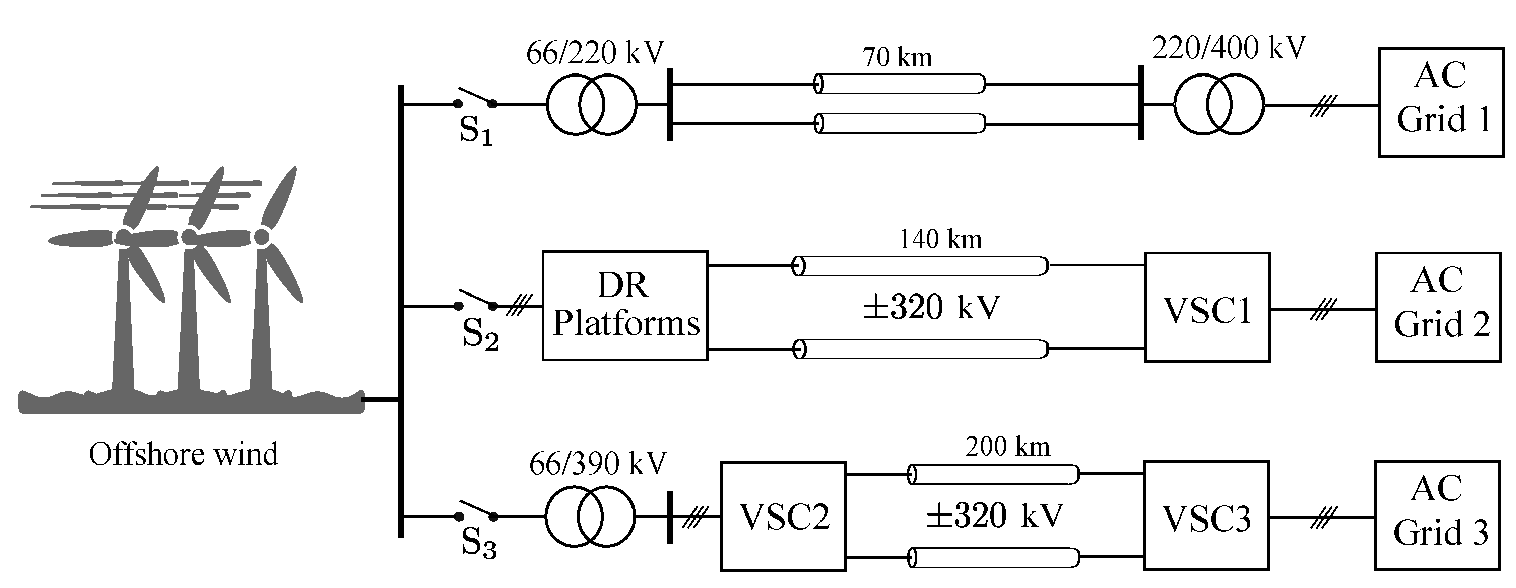
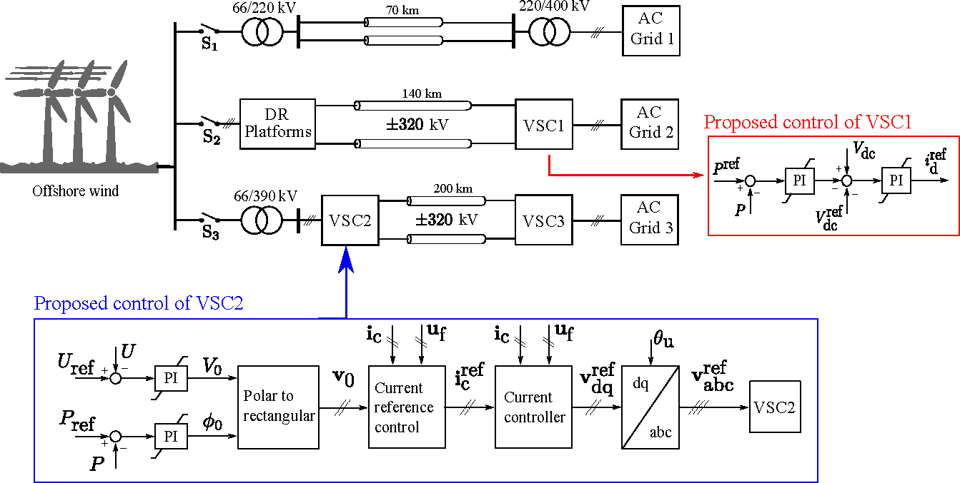
In this paper, the simultaneous use of three different power transmission links integrating a large OWF is investigated. It is assumed that an OWF, as shown in
Figure 1, delivers the power to different onshore AC systems via HVAC, VSC-HVDC, and DR-HVDC transmission links. Control systems for VSCs are proposed such that the power flow through each link is controlled. Since the operation of the WTs and the DR-HVDC link rely on the AC grid that either the HVAC or the VSC-HVDC links provide, the control of the only offshore VSC (in the VSC-HVDC link) is significantly important. If the HVAC link is disconnected, the VSC-HVDC link must immediately and without interruption take over the grid-forming responsibility. A novel control scheme is proposed for the VSC-HVDC link. In such a scheme, the offshore VSC operates in grid-following mode when the HVAC link is connected and switches seamlessly to grid-forming mode when the HVAC trips by detecting the offshore frequency deviation. Moreover, a new power flow control method is proposed for DR-HVDC. In such a method, a proportional-integral (PI) regulator in an outer loop controls the power flow through such a link by manipulating its onshore HVDC terminal voltage. The proposed DR-HVDC power control makes the DR operation independent of OWF control, which is a solution for the problem mentioned above regarding DR operation in a hybrid connection.
The rest of the paper is organized as follows. The investigated system is described in
Section 2. The proposed control schemes are presented in
Section 3. In
Section 4, the considered scenarios are described and corresponding simulation results are presented and discussed. Finally, concluding remarks are made in
Section 5.
2. Model Description and Operation
The studied system, shown in
Figure 1, includes an HVAC, a VSC-HVDC, and a DR-HVDC transmission link, connecting a large OWF with three different onshore AC systems. An offshore supervisory control is assumed to distribute the power generated by the OWF over the transmission links. Each HVDC link can control its power flow to follow the dispatch from the supervisory control, and the rest of the OWF output power is exported through the HVAC link as a result.
The system has a total of three HVDC VSCs (in the HVDC links), which control the overall power flow and HVDC link voltages. Such converters are assumed to be modular multilevel converters (MMCs) and are represented by the generic models proposed in [
15].
The DR-HVDC offshore terminal in
Figure 1 consists of three DR platforms connected in series. Each DR platform consists of two (uncontrolled, line-commutated) diode-based 12-pulse rectifiers connected in series, with the corresponding reactive power compensation and filter bank on their AC side.
The offshore wind farm is modeled as aggregated IECfull-converter (Type-4) wind turbines (WTs) based on the aggregation method given in [
16]. Each WT grid-side converter operates in grid-following mode and uses conventional vector current control [
17]. As described by (
1), WT reactive and active power outputs are regulated by means of outer loops with proportional controllers (droops) acting on the errors in AC terminal voltage (magnitude) and frequency, respectively, where
and
are the corresponding proportional gains.
,
,
, and
are determined by the offshore supervisory control.
3. Control Systems
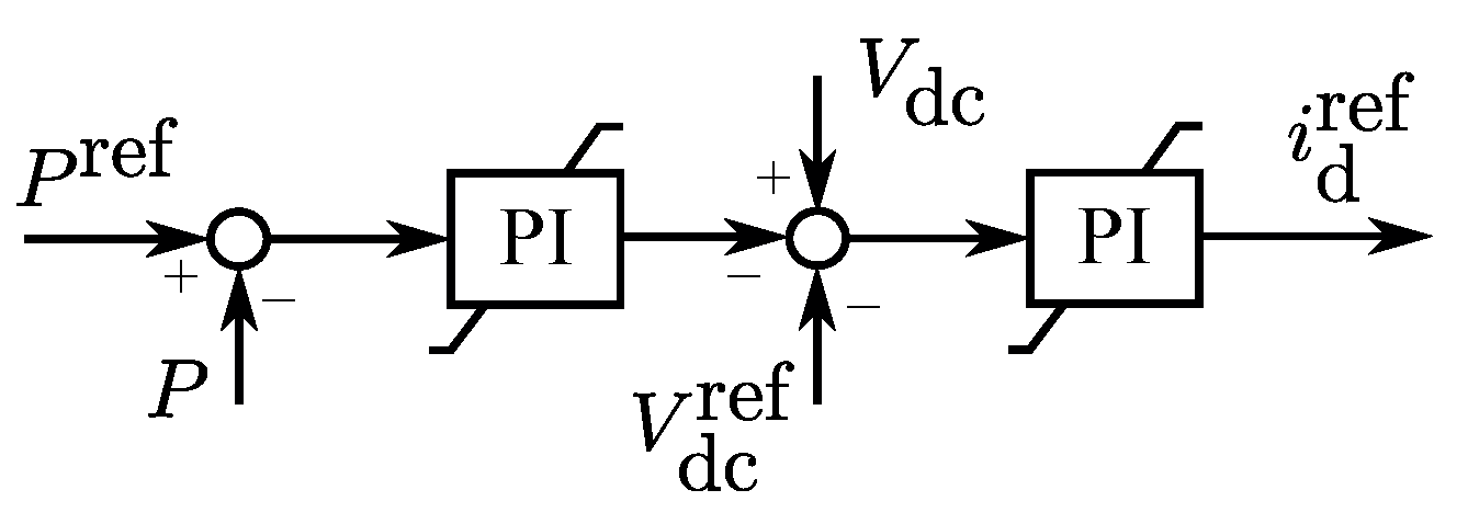
The control schemes of the three HVDC VSCs in the studied system are discussed in this section. VSC1 controls the power flow in the DR-HVDC link by manipulating its DC terminal voltage according to the proposed cascaded control scheme shown in
Figure 2. Although the DC-link voltage is influenced by the offshore alternating voltage, due to the diode rectifiers characteristics, including the DC-link voltage control in the proposed control scheme, shown in
Figure 2, can limit the voltage deviations.
VSC2 and VSC3 control the power flow and voltage, respectively, in the VSC-HVDC link. Two objectives are considered when controlling VSC2. Firstly, it should operate in grid-following mode when the HVAC link is connected and in grid-forming mode if such a link is disconnected. Secondly, it should control active and reactive power independently when operating in grid-following mode, even if the offshore AC grid is weak. Conventional controls are not applicable for VSC2, as they cannot seamlessly switch between grid-following and grid-forming modes.
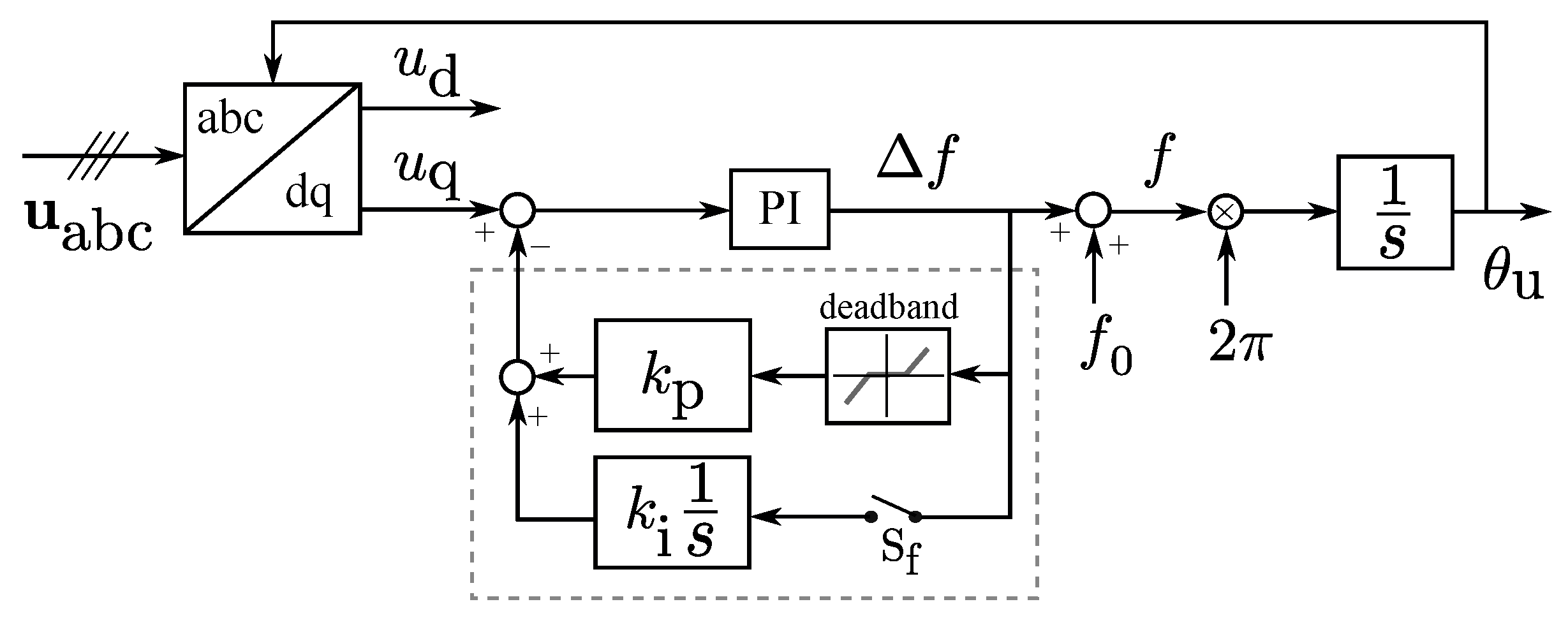
New phase-locked loop (PLL) and converter control approaches are proposed for VSC2. The model of the proposed PLL is shown in
Figure 3. The control blocks shown inside the dashed rectangle are added to a conventional PLL. In the case of HVAC outage, the offshore frequency drifts and goes beyond the deadband limits. The proportional feedback loop with the gain
resists against a high-frequency change. The switch
is closed by offshore supervisory control when the HVAC outage is detected. The integrator with the gain
then forces the frequency deviation,
, to return to zero. Therefore, the PLL generates a reference signal,
, with a constant frequency,
, and no longer follows the grid, instead forming an AC grid. In this case, when the converter switches from grid-forming to grid-following, the switch
is opened, and the integrator is reset to zero.
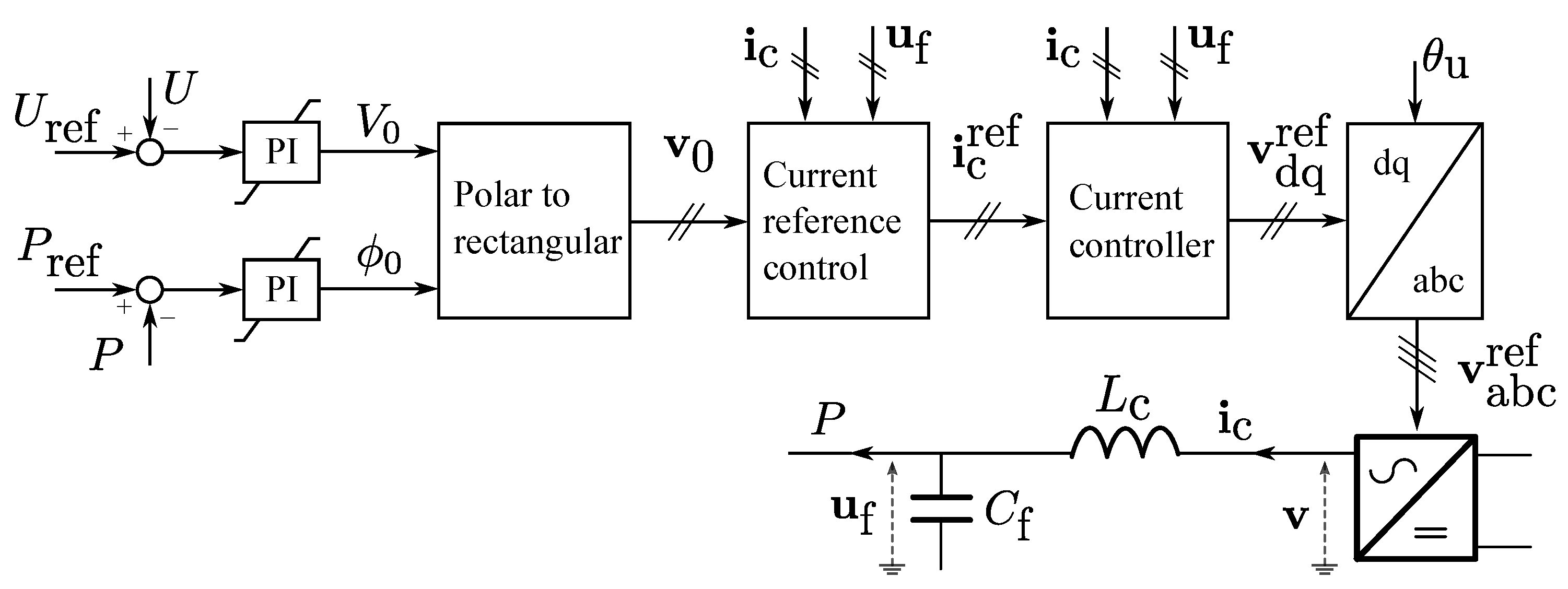
The proposed control scheme for VSC2, shown in
Figure 4, is a PLL-based power-angle control [
18,
19], which uses the inner current control loops (
current reference control and
current controller in
Figure 4), proposed in power-synchronization control [
20,
21]. In the proposed controls, VSC2’s active power output is controlled by the converter’s voltage angle. VSC2’s filter bus alternating voltage is controlled by the converter’s voltage magnitude. The converter’s current components (in the rotating reference frame) are controlled in the same way as in power-synchronization control, but a PLL is used to generate the transformation angle,
, i.e., synchronize with the offshore AC grid.
In the control block diagram shown in
Figure 4,
is the VSC2 filter bus voltage (complex space) vector, with magnitude
. The initial references for the converter AC terminal voltage vector magnitude,
, and angle,
, are generated by two proportional-integral (PI) regulators, which control
U and the active power output
P, respectively. Such a vector,
, is then expressed in rectangular form.
Besides power and voltage, the converter current must also be controlled to limit the fault current and remove high-frequency resonances from the current. The current vector reference,
, is generated using the voltage reference vector
. To do so, the technique proposed in [
20] is used as:
where
is the desired closed-loop bandwidth of the current controller. The functions
and
are respectively low- and high-pass filters with the following expressions:
where the bandwidth
is typically in the range of
, and the bandwidth
is chosen low enough to cover all the possible resonances in the AC system, typically in the range of
[
20]. The gain
determines the level of damping and is chosen in the range of
.
The current controller block in
Figure 4 uses the reference current,
, to generate the converter’s reference voltage by the following inner-current control approach:
Substituting Equation (
2) into Equation (
4), the voltage-vector control law [
20] can be observed as:
which shows how high-frequency resonances can be filtered out by the controller. Moreover, there is a current limiter inside the current reference control block to limit the fault current.
During the transition from grid-following to grid-forming, reaches one of the power controller’s limits. The controller is thus overridden, and the converter operates as a slack bus, producing a voltage with a fixed frequency.
4. Simulation Studies
In this section, the considered scenarios are described and the corresponding results of the dynamic simulations performed in PSCAD are presented and discussed. A simulation time step of 30
was used. First-order low-pass filters with a time constant of
were applied to the presented active and reactive power responses. The power transmission cables were modeled with the
model with the lumped parameters given in
Table 1. This table also presents the parameters of the power and voltage control loops of OWF and HVDC converters.
It is assumed that OWF can produce 2000 MW. The HVAC transfers 450 MW, DR-HVDC 800 MW, and VSC-HVDC 750 MW when the OWF generates its nominal power.
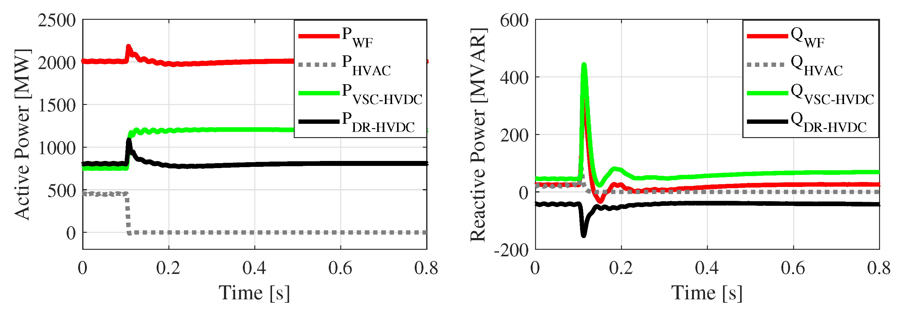
4.1. Transition from Grid-Following to Grid-Forming
In the first simulation scenario, it was assumed that the HVAC link trips and the VSC-HVDC takes the responsibility of maintaining the offshore frequency, forming the offshore AC grid. The results for this scenario are shown in
Figure 5,
Figure 6,
Figure 7 and
Figure 8.
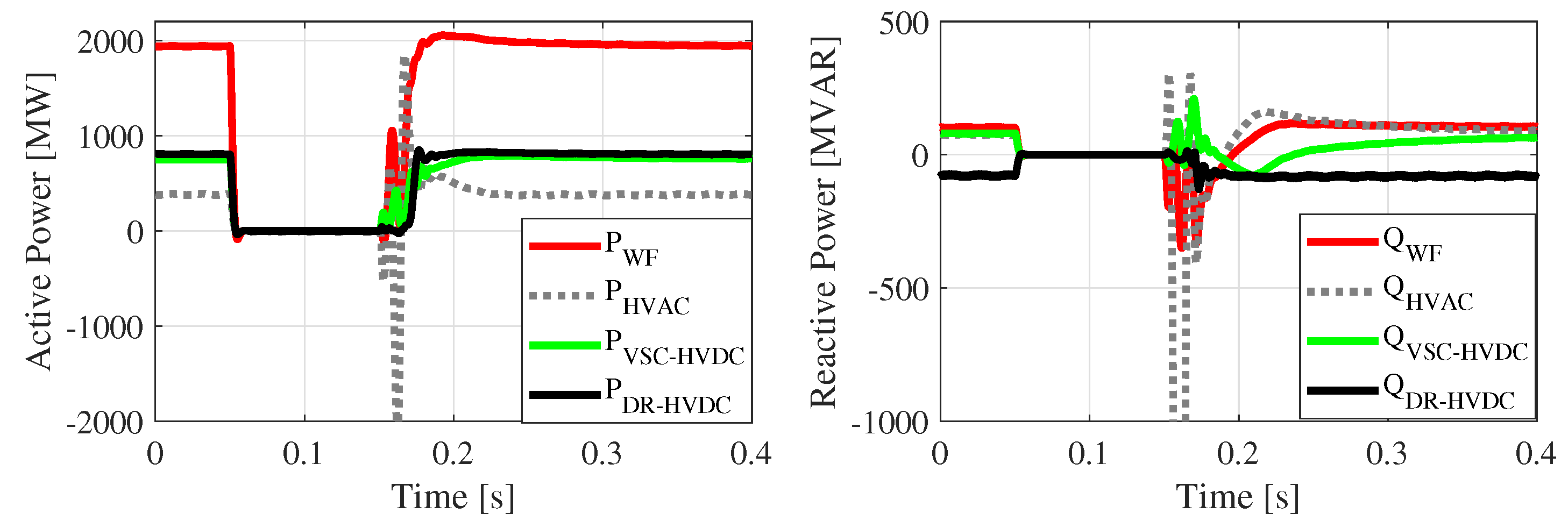
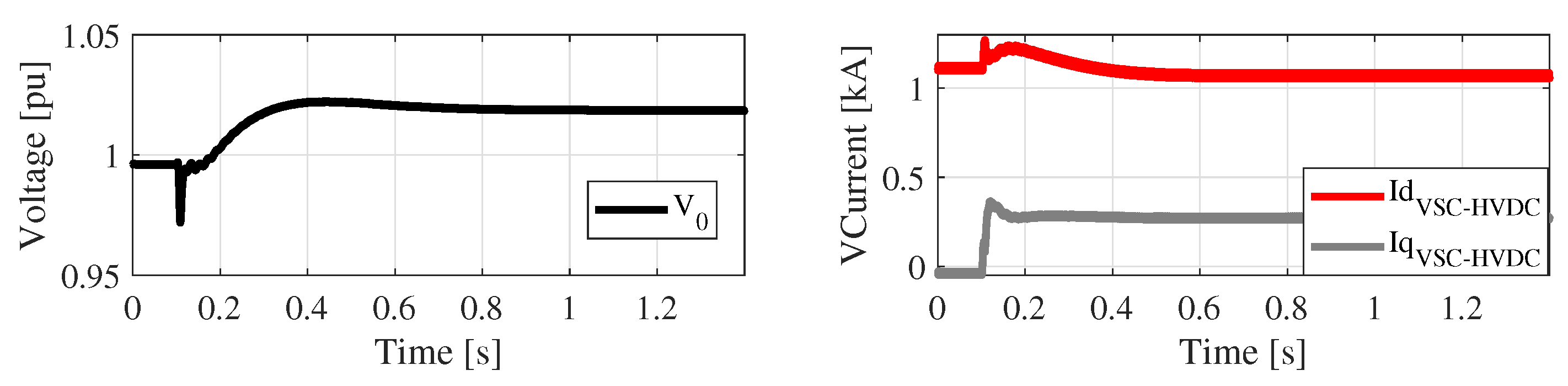
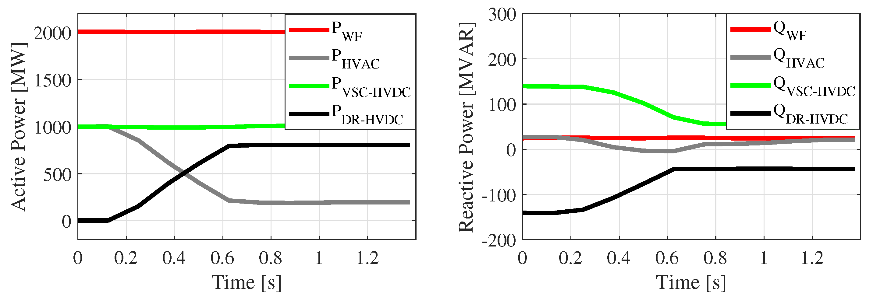
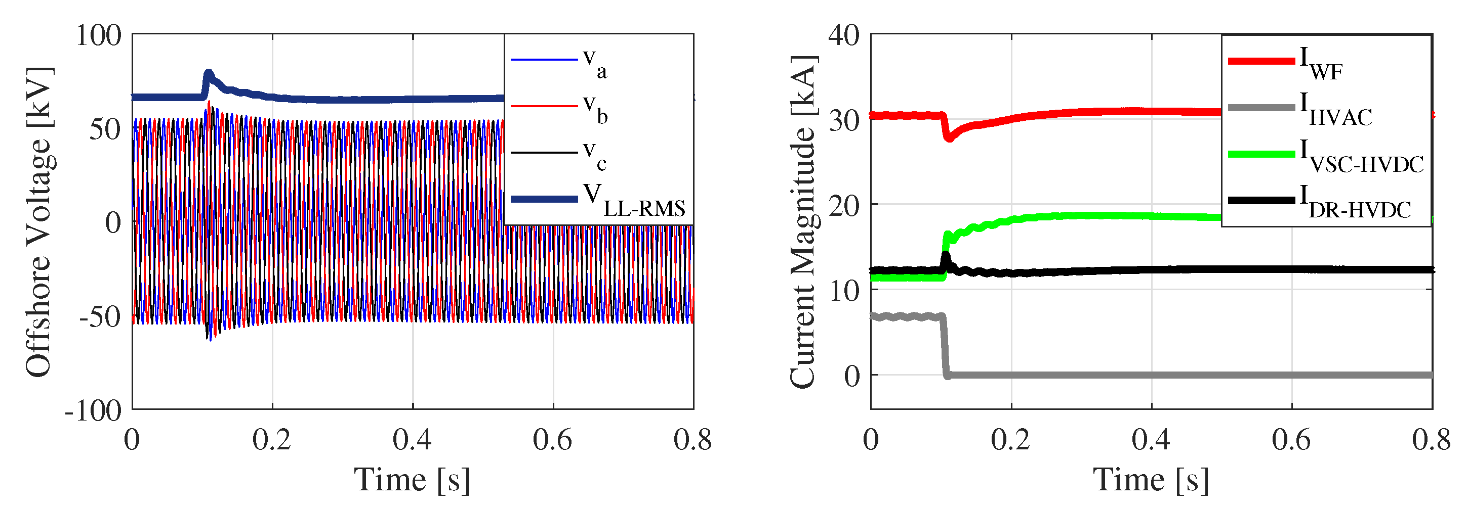
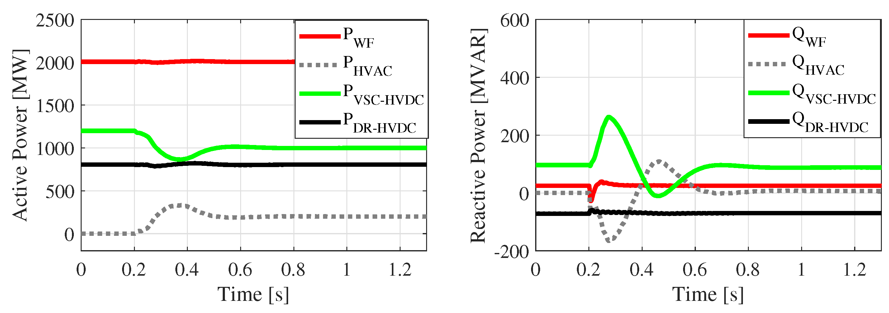
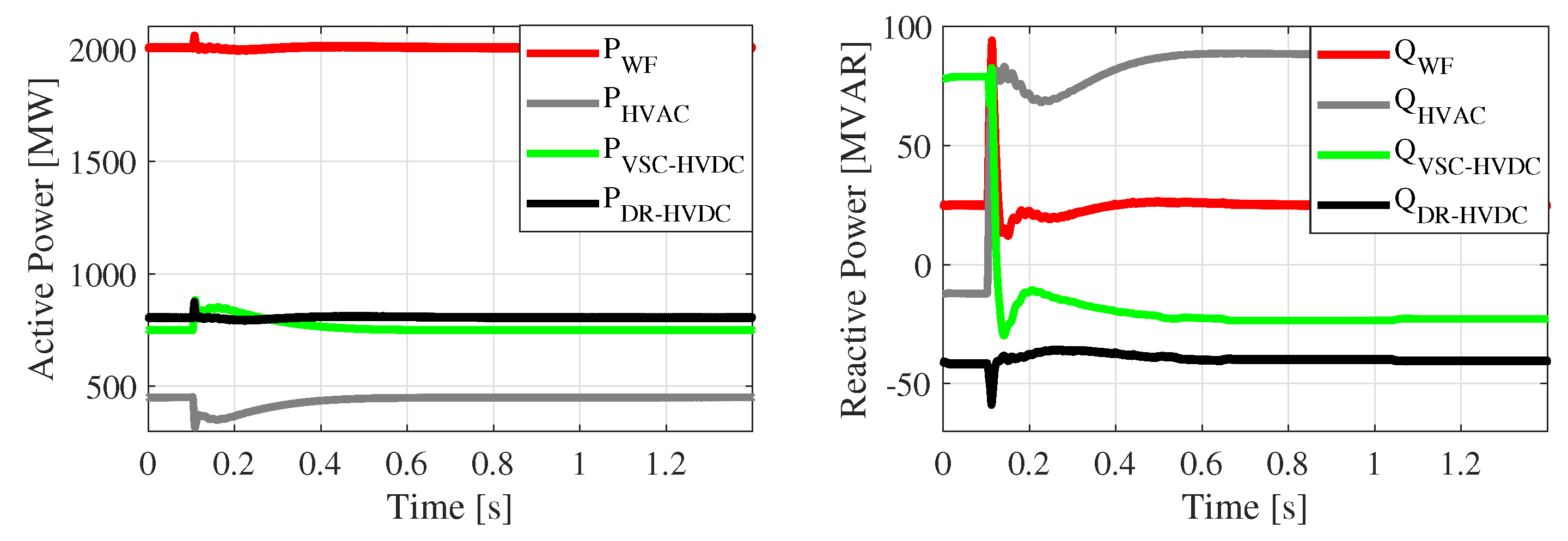
As shown in
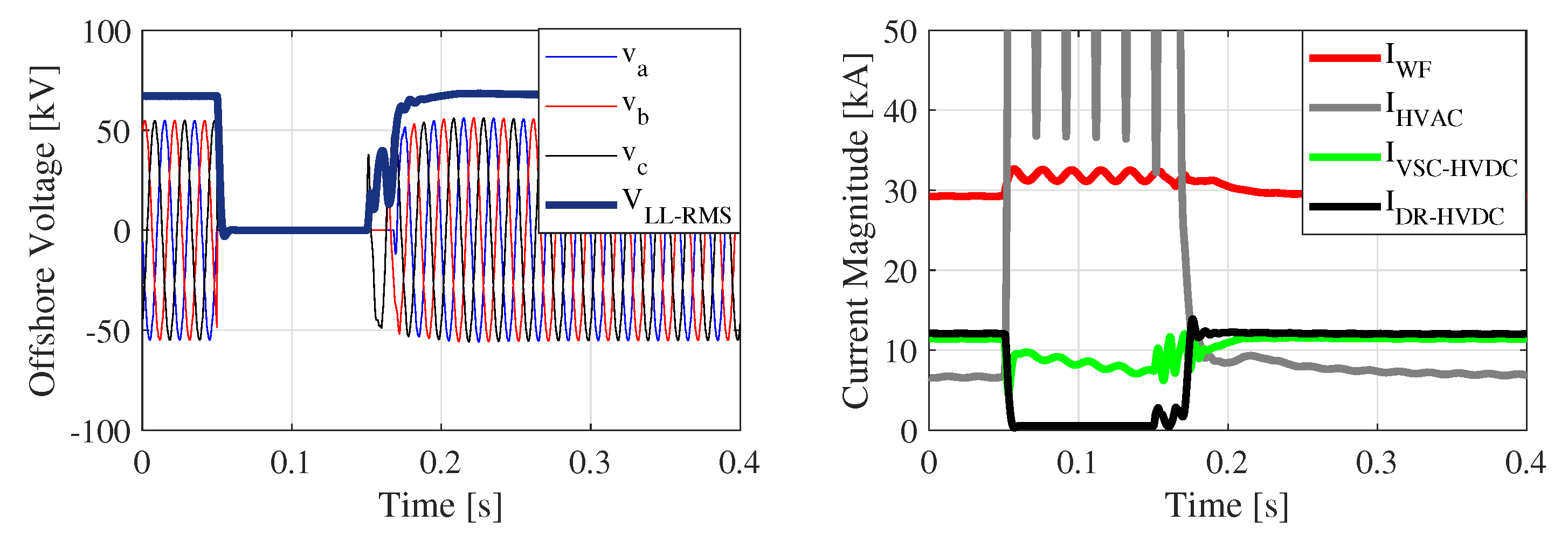
Figure 5, active and reactive power, previously flown through the HVAC, were taken over by the VSC-HVDC after the transition. It was assumed that the VSC-HVDC had a nominal capacity of 1400 MVA; therefore, it could transfer the additional power after the HVAC outage. The voltage of the offshore common coupling point (PCC) and root mean squared (RMS) values of the currents of the OWF, as well as the transmission links are shown in
Figure 6. The voltage rose slightly at the beginning of the transition due to the presence of capacitors in the diode rectifier station. Moreover, there was an interaction between the controllers of the VSC2 and WT converters, which resulted in a reactive power spark; however, under the converters current limit.
Figure 5 shows the active and reactive power of OWF and transmission systems, when the HVAC trips and VSC2 undergoes a transition from grid-following to grid-forming operation.
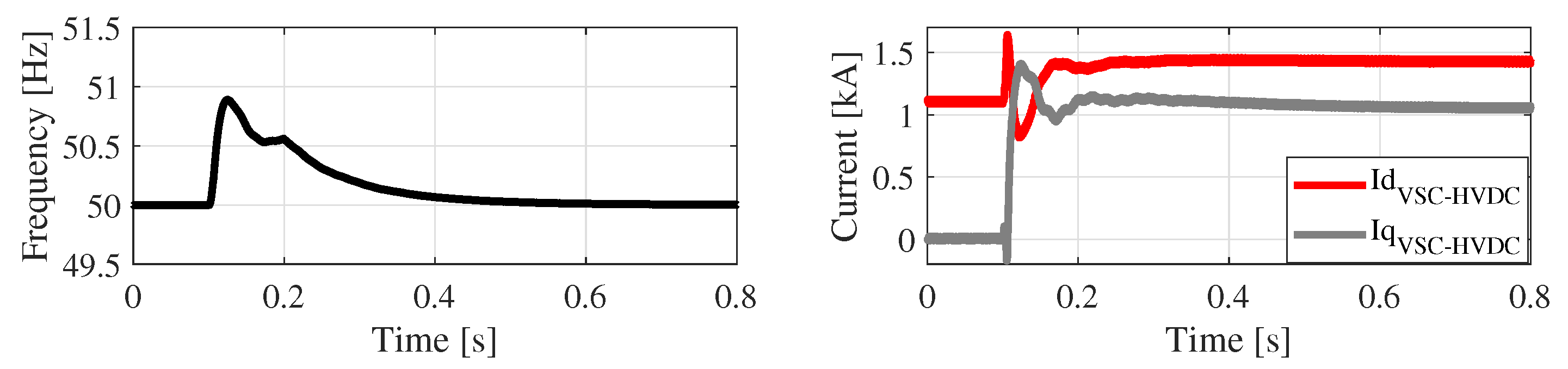
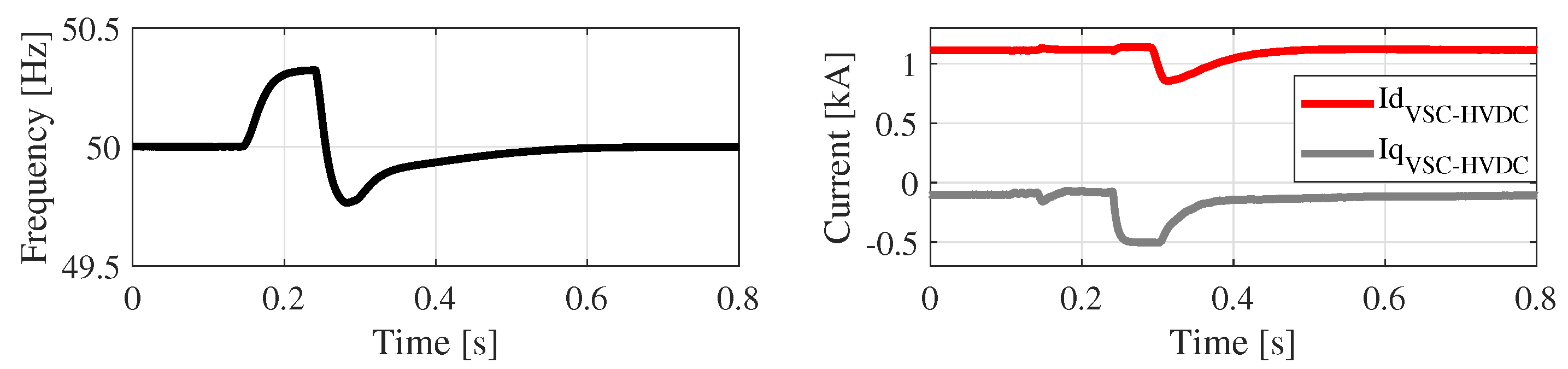
The offshore frequency before and after transition is shown in
Figure 7. The frequency was measured using the PLL model given in
Figure 3. Immediately after the transition, the frequency jumped up due to the independent control of active power and alternating voltage in VSC2. The feedback loop in the PLL with gain
restrained the jump. The switch of the integral feedback,
, was closed after 100 ms of HVAC link outage and brought the frequency back to its nominal value as shown in
Figure 7. The VSC2 current in the dq frame is also shown in
Figure 7. Since the controller was in the grid-forming mode after the transition and the synchronous frame did not follow the VSC2’s filter bus, the dq currents lost their patterns from the pre-transition period and no longer resembled the active and reactive power patterns. The initial references of VSC2’s voltage angle and magnitude are shown in
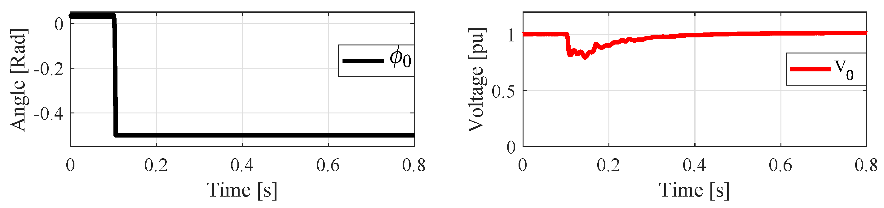
Figure 8. The voltage angle fell to the lower limit of the PI controller and was fixed there during the entire time when VSC2 operated as grid-forming. This implies that the power control loop was not effective anymore. However, as shown in
Figure 8, the voltage controller that generated the initial reference for the converter, experienced a short-time transient, almost 200 ms, recovered the offshore AC voltage and maintained it during the post-transition period.
4.2. Transition from Grid-Forming to Grid-Following
For different reasons such as fault or maintenance, the HVAC link might be disconnected from the offshore network, and VSC2 operates as grid-forming. The situation where the HVAC link is re-connected is simulated in this section to investigate the transition of the proposed controller from grid-forming to grid-following.
Figure 9,
Figure 10 and
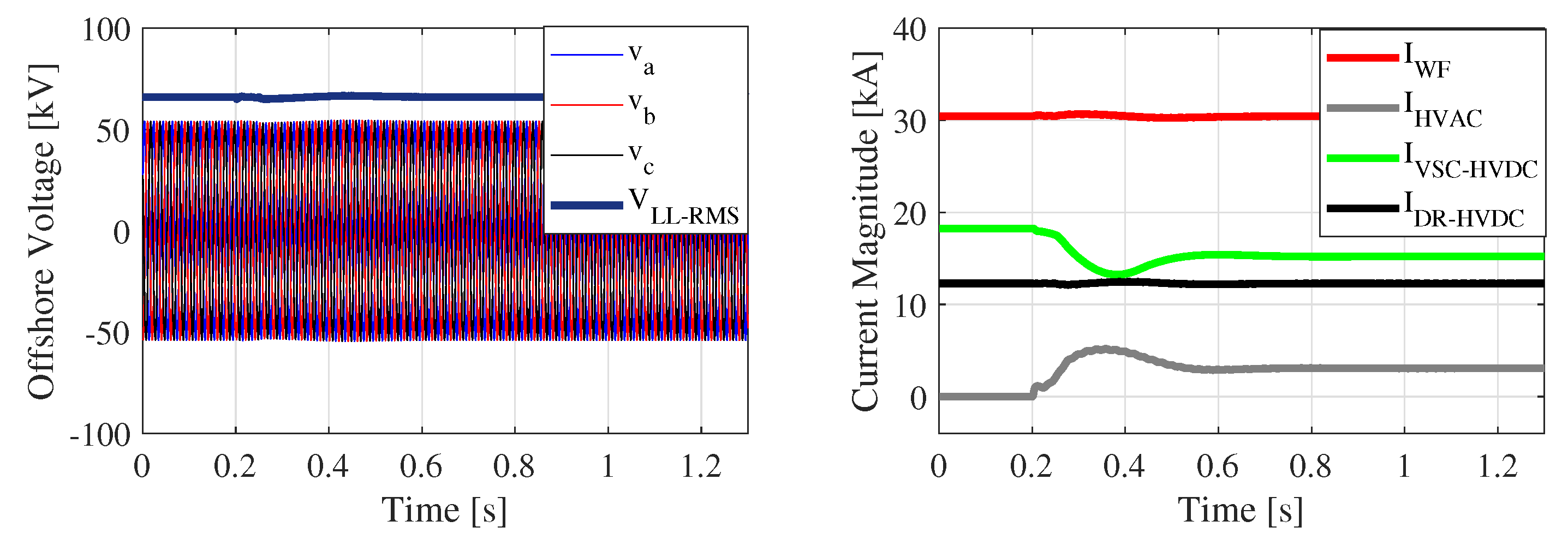
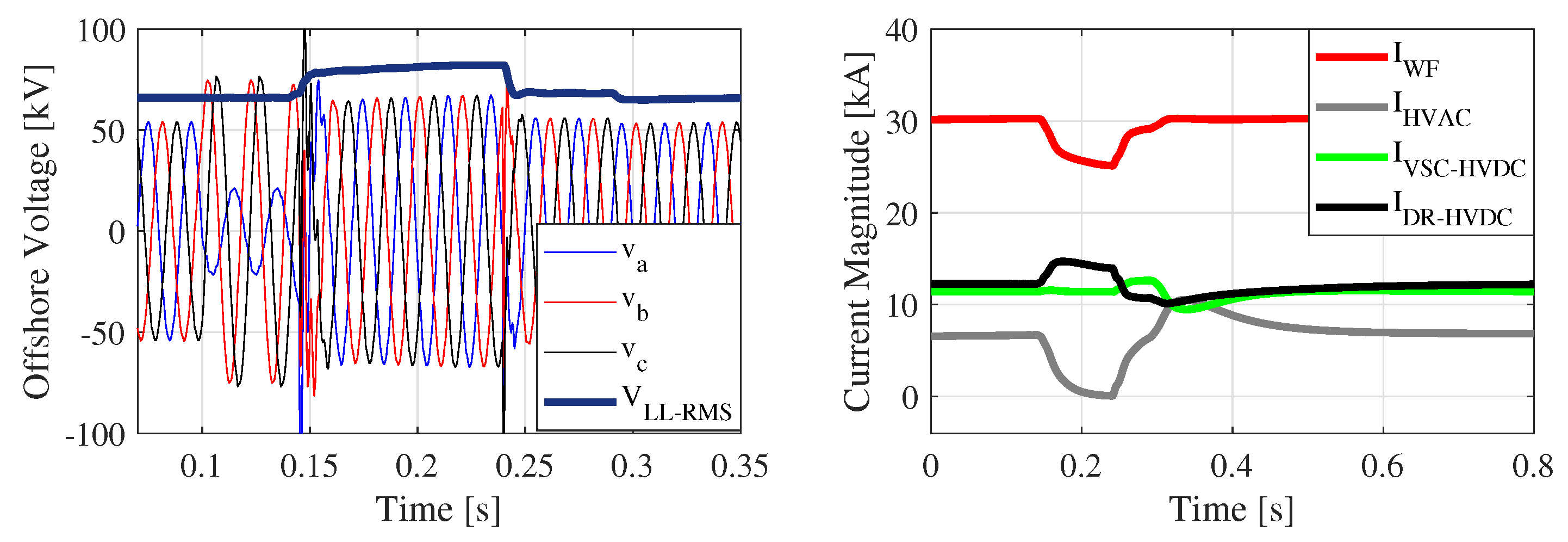
Figure 11 show the simulation results for the re-connection of the HVAC link. It is obvious that only VSC2 played a role in the transition and balanced the power-flow between transmission links, which was the main goal of the proposed control scheme. The offshore AC-link voltage in
Figure 10 shows the smoothness of the transition.
4.3. Short-Circuit on Offshore PCC
To investigate the fault current-limiting capability of the proposed control system for VSC2, a three-phase short-circuit was applied to the offshore PCC for 100 ms.
Figure 12 shows the offshore PCC voltage and RMS currents of OWF and transmission links. The AC-side current of DR-HVDC became zero since the diode rectifiers did not reverse the current, and hence, no current flowed to the short-circuited point. The OWF’s current was controlled through the WT converters, and its magnitude was limited under the fault. The current of the VSC-HVDC was also limited, which showed the fault current-limiting capability of the proposed controller. As shown in
Figure 12, it was only the HVAC current that was not limited during the fault, which is almost the case in any AC system without fault current limiters. Active and reactive powers for this scenario are shown in
Figure 13. The recovery capability of the proposed controllers for VSC1 and VSC2 is evident from this figure. There was a transient interaction between OWF and VSC2 immediately after the fault clearance, which resulted in the reactive power interchange between the two. The system reached the steady-state in less than 100 ms. This indicated an acceptable capability of the proposed controllers to limit the fault current.
A comprehensive stability analysis of an offshore wind farm required more detailed models of wind turbines and their controls, cable arrays, wind farm supervisory control, and so on. However, since an aggregated representation of the offshore wind farm as a single equivalent wind turbine was used in this paper, the scope of the wind farm’s stability analysis was limited to whether it can stay connected to the grid under severe fault conditions (e.g., 100-ms three-phase short-circuit), prioritize the control of active or reactive power (or AC voltage) during the fault (in compliance with corresponding grid code requirements), and recover to normal operation immediately after the fault is cleared. The proposed coordinated control of the three different transmission links did not affect the operation and control of the offshore wind farm significantly. Moreover, the proposed control enabled a seamless transition of the offshore AC network from AC-connected operation to AC-disconnected operation (DC-connected only), without imposing any restrictions on or changes in the control and operation of the offshore wind farm. Therefore, the proposed control did not impact the stability of the offshore wind farm. However, key wind farm variables such as voltage, current, and control signals are presented in the simulation results to confirm the stable wind farm operation under severe fault conditions.
4.4. Single-Phase Short Circuit on HVAC Link
Anther fault scenario was considered as a single-phase short-circuit on the high voltage side of the HVAC link. The results for this scenario are presented in
Figure 14,
Figure 15 and
Figure 16. After detecting the fault, the HVAC link tripped and reconnected again when the fault was cleared. This means that for a short time, VSC2 operated as grid-forming under faulty conditions and experienced two transitions in a very short time. Since the fault was asymmetric and AC voltage on the offshore side dropped in one phase and rose in two others, the immediate active power rise occurred in DR-HVDC. However, the VSC-HVDC tried to increase its power to establish the balance between generated power by OWF and the exported power by the links.
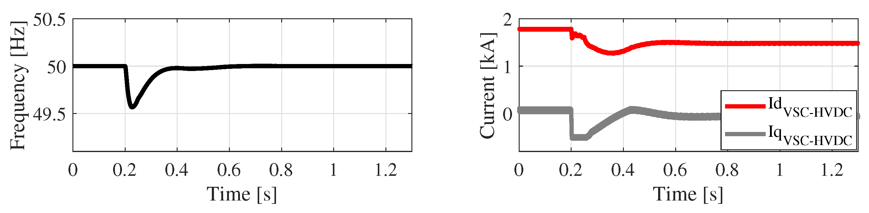
Figure 16 shows that offshore frequency and VSC2 currents were all under permitted limits.
4.5. Weak AC Link Interconnection
To evaluate the capability of the proposed controller for VSC2, in the case that the AC connection was weaker (low short-circuit ratio), it was assumed that one of the cables of the HVAC link tripped and the offshore AC grid became weaker.
Figure 17 shows the active and reactive power of OWF and the transmission links of this scenario. After the cable outage, the VSC-HVDC immediately responded to the active and reactive power change of the HVAC link. In fact, the VSC2 took the responsibility of maintaining the continuous operation of OWF and DR-HVDC. However, since the remaining cable of the HVAC link can transfer the 450-MW power, the VSC2 returned the active power to its reference value after a transient.
Figure 18 shows the initial voltage reference and currents of the VSC2. The voltage reference was increased to generate more reactive power to compensate for the HVAC reactive power.
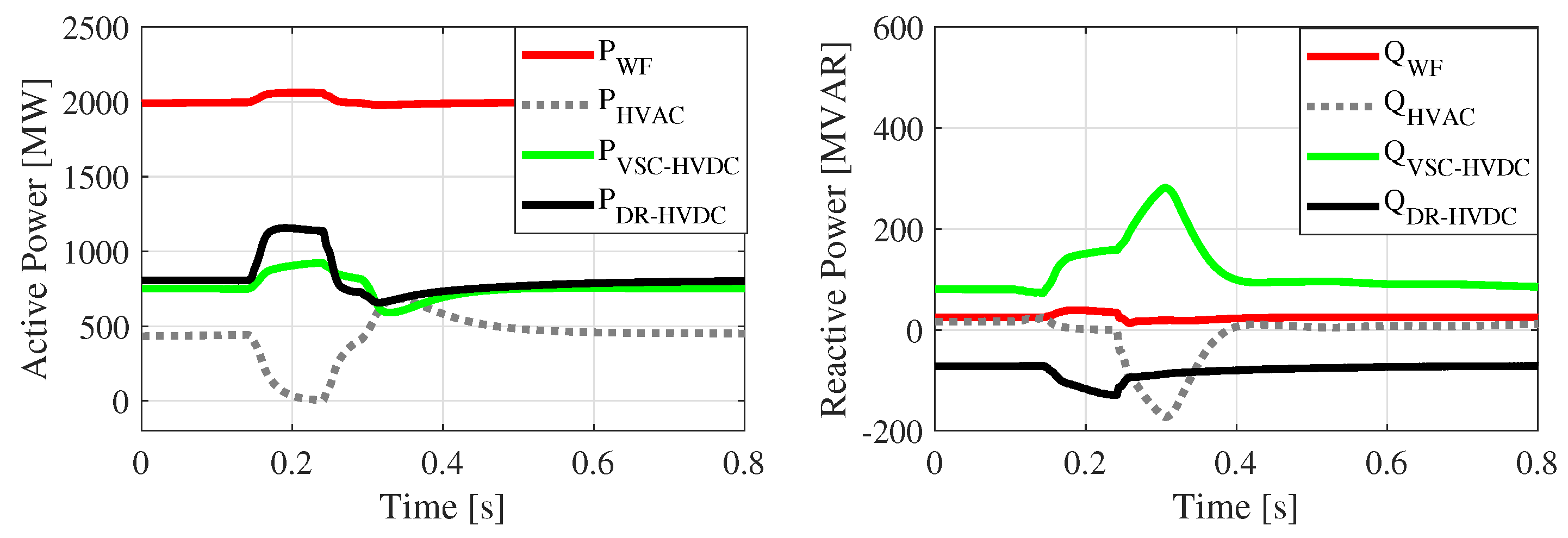
4.6. DR-HVDC Link Power Ramp-Up
To evaluate the performance of VSC-HVDC control against a significant change in the DR-HVDC’s operation, it was assumed that at the beginning, the DR-HVDC was not conducting and transferred no power. The active power setpoint of the VSC-HVDC was 1000 MW in this scenario. The DR-HVDC started exporting power with a ramp rate of 2000 MW/s. As shown in
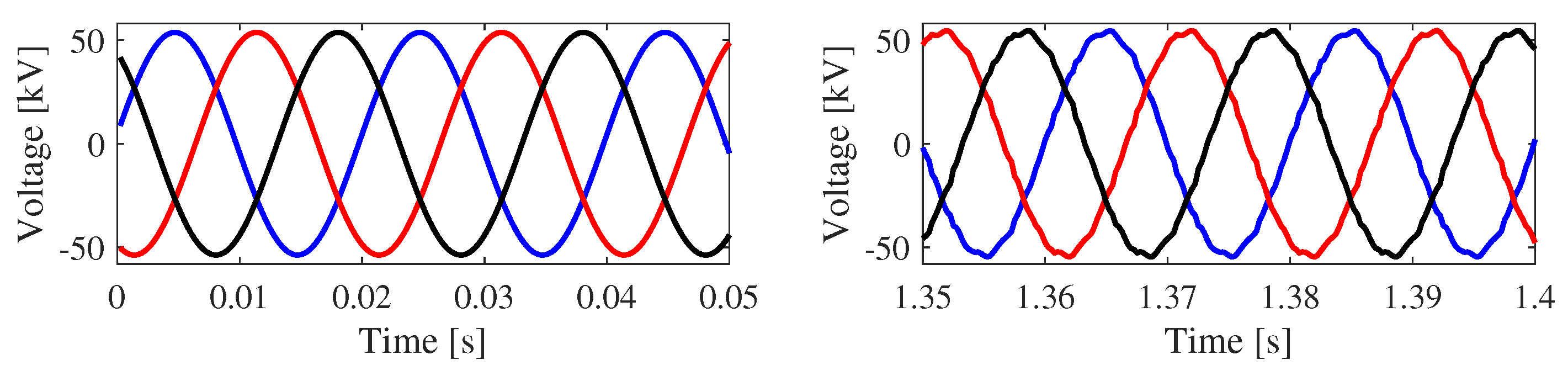
Figure 19, the active power of VSC-HVDC and OWF was constant during the time when the DR-HVDC started exporting power. Since the filters and reactive power compensators of the DR-HVDC were connected even before its active power conduction, they impacted the entire reactive power dispatch of the transmission lines on the offshore side. However, the VSC2 could counteract with DR-HVDC reactive power change by controlling the offshore AC voltage. The three-phase alternating voltage waveforms of offshore PCC are shown in
Figure 20. Since the diode rectifiers created harmonic distortions on the AC voltage, when conducting, it was observed that the alternating voltage waveforms were not as smooth as they were before DRs’ conduction. The filters on the DRs’ station, however, limited the harmonic distortions to an acceptable level.

 ,
, 


