Abstract
Offshore high-voltage DC (HVDC) grids are developing as a technically reliable and economical solution to transfer more offshore wind power to onshore power systems. It is also foreseen that the offshore HVDC grids pave the way for offshore wind participation in power systems’ balancing process through frequency support. The primary frequency control mechanism in an HVDC grid can be either centralized using communication links between HVDC terminals or decentralized by the simultaneous use of DC voltage and frequency droop controls. This paper investigates the impact of both types of primary frequency control of offshore HVDC grids on onshore power system dynamics. Parametric presentation of power systems’ electro-mechanical dynamics and HVDC controls is developed to analytically prove that the primary frequency control can improve the damping of interarea modes of onshore power systems. The key findings of the paper include showing that the simultaneous use of frequency and DC voltage droop controls on onshore converters results in an autonomous share of damping torque between onshore power systems even without any participation of offshore wind farms in the frequency control. It is also found that the resulting damping from the frequency control of offshore HVDC is not always reliable as it can be nullified by the power limits of HVDC converters or wind farms. Therefore, using power oscillation damping control in parallel with frequency control is suggested. The analytical findings are verified by simulations on a three-terminal offshore HVDC grid.
1. Introduction
The technical and regulatory feasibility of providing frequency support from intermittent renewables to power systems has attracted attention. Many experiments have been carried out to investigate and demonstrate the participation of wind power in frequency control. In a project conducted at a 21 MW wind farm in west Denmark [1], 5% of available power has been reserved to provide downward regulation. In [2], a Belgian wind farm with 81 MW capacity has been tested to provide frequency restoration reserve, and its feasibility has been studied from the technical and regulatory point of views.
A generator must be down-regulated to have some reserve (headroom) power to participate in the primary frequency control. The reserved power is proportionally—respecting frequency droop—released in response to frequency drops. The reliability of the frequency control must be high to establish a balance between demand and production of power systems. To increase the reliability of frequency support from high-voltage DC (HVDC) connected offshore wind farms (OWFs), an autonomous frequency control (AFC) scheme, without using communication links between onshore and offshore, has been proposed in [3]. In this control, offshore frequency mirrors the onshore frequency by regulating the DC-link voltage.
Using communication links between HVDC terminals, a centralize frequency control (CFC) can be achieved. In CFC the supporting (required) power of frequency control can be dispatched among OWFs and other onshore AC systems depending on the amount of reserved power each system has.
Some studies have been carried out on implementing the AFC from offshore multi-terminal HVDC networks [4,5,6,7,8,9]. To create an AFC mechanism, the onshore converters use frequency droop control, which transforms frequency changes to DC voltage changes. Converters on the other ends (OWFs and/or other onshore systems) react to DC voltage changes by adjusting their active power. Although this method of frequency control is relatively more reliable and economical, it can result in some challenges. In [5,10,11] it has been shown that using AFC in offshore HVDC networks, the delivered power to onshore systems—in response to a frequency drop—is less than what is expected by system operators.
The primary frequency control has slower dynamics (hundreds of milliseconds), compared to electro-magnetic transients of entire electric circuits and dynamics of HVDC’s power control (tens of milliseconds). Therefore, it is not expected that adding primary frequency control would significantly impact the HVDC dynamics. However, the frequency control of HVDC can impact the electro-mechanical dynamics of power systems [12,13]. In [13], the dynamics of frequency control of a multi-terminal HVDC has been investigated, and in [12] an analytical study has been conducted to prove that primary frequency control could improve the damping of interarea modes of AC power systems. In none of these references, contributions from wind power are considered.
The contribution of OWFs to power oscillation damping (POD) has been addressed in the literature [14,15,16,17,18,19]. The impact of HVAC-connected OWFs on POD has been studied in [14]. More detailed studies have been conducted in [15], where it has been shown that the level of OWF model aggregation has a limited impact on the resulting damping. The POD control of VSC/HVDC/connected OWFs has been studied in [17], where design principles have been derived for the POD controllers, and practical POD implementation issues have been discussed. The POD control implementation on diode rectifiers connected OWFs is studied in [19]. However, no study, to the best knowledge of authors, has analytically investigated the impact of offshore HVDC frequency control on POD of onshore systems, which is the main contribution of this paper.
In this paper, the impact of primary frequency control of offshore multi-terminal HVDC grids on interarea modes of power systems is studied, analytically. Small-signal models of offshore HVDC’s control and onshore AC system’s electro-mechanical dynamics are developed in Section 3 for both AFC and CFC. To derive an analytical expression of interarea modes, the studied onshore system is modeled as two synchronous machines interconnected via a tie-line. The offshore HVDC grid is modeled by DC-link voltage and frequency droop control parameters, considering some simplifications. The dynamic characteristic of the studied system is derived in Section 4, and its complex-conjugate eigenvalues—related to interarea modes—are obtained as a function of mechanical and HVDC control parameters. It is proven that the frequency control of offshore HVDC can improve the damping of the interarea modes. Moreover, it is shown that the mentioned improvement is not always reliable since the frequency-supporting power can be limited to a fixed value without reflecting onshore system oscillations. This case can occur when the reserved (down-regulated) power of offshore wind is released fully and/or HVDC converters reach their power limits and operate with a fixed power reference. To increase the reliability of improving the damping of onshore system oscillations via HVDC it is suggested to use a POD control in parallel with primary frequency control. The analytical findings are verified in Section 5 by simulating a three-terminal offshore HVDC grid whose onshore converters supply a power system, which has two areas with a possibility of oscillating against each other. The paper concludes the study in Section 6.
2. HVDC Model and Control
The offshore HVDC network model and converter control systems are presented in this section.
2.1. Offshore HVDC Network Model
The offshore three-terminal HVDC topology used for studies is shown in Figure 1. It has an OWF and two onshore AC systems. Each of the onshore systems is modeled as an aggregated synchronous machine equipped with an automatic voltage regulator (AVR) and a turbine-governor set. The two AC systems are interconnected via an AC tie-line in which the active power flows from System 1 to System 2.
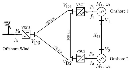
Figure 1.
Offshore HVDC grid used for dynamic studies.
Since the study presented in this paper is of analytical type and mathematical equations are used to describe the dynamic behavior of the entire system to show the impact of frequency control on POD, the HVDC grid model is deliberately chosen to be small. However, three-terminal HVDC has been adopted to include the interactions with converters’ controllers. Having two onshore terminals makes it possible to derive an analytical expression of AC systems interactions. The system shown in Figure 1 can be a simplified resemblance of real systems, which may evolve in near future. For example, it can resemble an OWF in the North Sea connected to two continental European countries, which are also linked through AC sides.
The offshore wind farm is modeled as IEC type-4 (fully rated) wind turbines using the aggregation method given in [20]. The OWF has 1000 MW generation capacity and the AC voltage of its collection system is 66 kV. The DC voltage of HVDC connections is 640 kV pole-to-pole, and modular multilevel converters are used for power conversion. Frequency in offshore and onshore AC networks is 50 Hz.
2.2. HVDC Control
The control of a multi-terminal HVDC grid can be implemented in different ways [21]. Master-slave control: One converter controls the DC-link voltage and rest of converters, active power. Without redundancy procedure, this control method can suffer from low security under forced converter outage [21]. Voltage margin control: Similar to the master-slave control, one converter maintains the DC-link voltage, while there are other converters providing backup to control the DC-link voltage in the case that the master converter fails [22]. Autonomous power sharing: The control of the DC-link voltage is distributed among some converters, using power-voltage droop control. When the DC-link voltage changes, the consequent power deviation is automatically shared among the converters, which have droop controls. This droop control is similar to power-frequency droop control in AC power systems. In this paper, the autonomous power sharing control is used.
To implement the AFC on the HVDC grid shown in Figure 1, the onshore frequency deviations must be transformed into DC-link voltage deviations by means of droop controls. When using autonomous power sharing control on both the onshore converters, VSC1 and VSC2, the frequency deviation can be included in their control as
where and are respectively the inverse of voltage and frequency droop gains. All parameters indicated with asterisks (*) represent the reference values. Since the onshore systems are interconnected through an AC cable, which has an equivalent reactance of , the frequency of both AC systems is the same. For the sake of simplicity, it is assumed that only VSC1 is equipped with the primary frequency control.
The AFC requires the offshore converter, VSC3, to measure the DC voltage deviations and convert it into offshore frequency deviations, as shown in Figure 2. It must be noted that VSC3 operates as a conventional grid-forming converter, controlling the offshore alternating voltage with a fixed frequency. In the case of using AFC, a DC-link voltage droop control, as shown in Figure 2, is added to the converter control to modify the offshore frequency. In Figure 1, if the OWF has a reserve capacity and is required to contribute in the AFC, its frequency is regulated as . The wind farm changes its output power—in wind turbines level—in response to offshore frequency-change as
which shows the output power of the OWF can be changed if the onshore frequency changes, without relying on any communication links between onshore and offshore. This is the basis of the AFC mechanism in an offshore HVDC grid. In (2), is the time constant of active power change of the OWF. Normally the commercial wind farm controllers have active power ramp-rate limiters to decrease mechanical stresses on wind turbines [17]. Assuming a ramp-rate of 0.1 pu/s for WTs and also assuming that 5% of nominal power of each WT is reserved for the primary frequency control, it can be expected that increasing 5% of power can take around 0.5 s time. This implies that the time constant is lower than 0.5 s. Here, it is estimated to be around 0.1 s, i.e., s.
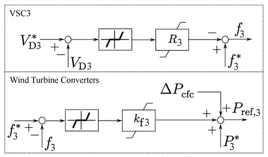
Figure 2.
Voltage and frequency droop control used for VSC3 and wind turbine converters.
In case of CFC, the onshore required power, , is sent to the OWF through a communication link, as shown in Figure 2. Therefore, the offshore power equation can be stated as
3. Developing Small-Signal Models
In this section, small-signal models are developed to study the electro-mechanical dynamics of the system shown in Figure 1 for both AFC and CFC of offshore HVDC networks. Some simplifications and assumptions are considered to develop the models. However, the assumptions are not made in the simulations.
- Both AC and DC electric systems are assumed to be loss-less.
- HVDC converter controls are much faster than electro-mechanical dynamics of the synchronous machines in AC grids. Therefore, the dynamics of HVDC controllers are neglected.
- Since the study aims the electro-mechanical modes of power systems, the electro-magnetic dynamics of electric circuits are neglected.
- To understand the oscillation damping effects of primary frequency control of HVDC, the effects of automatic voltage regulators (AVRs), power system stabilizer (PSS), and turbine-governor are not included when deriving the small-signal models of the systems.
- Since the dynamic equations are developed linearly, the effects of all limiters and communication delays (tens of milliseconds) are neglected.
3.1. Electro-Mechanical Dynamics
The aggregated synchronous machines, representing two areas, have rotating masses with inertia constant of and , and dampings with coefficients of and . The dynamic of these machines is stated as
where and are respectively the mechanical speed and angle. and with are respectively mechanical and electrical load power. and are HVDC active powers fed to onshore system respectively from VSC1 and VSC2. The power-flow direction through the AC link is assumed to be from onshore 1 to onshore 2. Light loading through the AC line are assumed, implying that the voltage-angle difference across the line is small, so that .
The dynamics of voltage control units are faster than that of active power control [23]. Therefore, for studies aiming the electro-mechanical dynamics, the AC voltage dynamics are neglected and and , in (4), can be assumed to be fixed in 1 per-unit. Linearizing (4) regarding the made assumptions, results in
where , and and can be obtained from (1) as explained in the following subsection.
3.2. Small-Signal Model
In per-unit system, electrical frequency is equal to the machine speed, i.e., . The loss-less assumption of DC links results in . Therefore, assuming no variation of reference parameters, (1) and (2) for AFC can be stated as
where indicates a small-signal variation of an electrical parameter. In (6) the OWF’s time constant is neglected. This is further discussed in Section 4. From (6), the power from HVDC grid to frequency deviations can be obtained as
and in the case of CLC in which the OWF uses (3) instead of (2), the power deviations of onshore converters can be obtain as
The derived equations, (5) and (7), can be represented as a small-signal block diagram show in Figure 3a for AFC. Using (5) and (8) a similar block diagram is developed for CFC shown in Figure 3b.
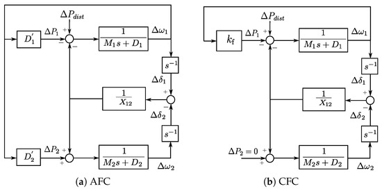
Figure 3.
Small-signal block diagrams of the system shown in Figure 1 with HVDC frequency control.
4. Analysis
In this section, the damping effect of HVDC frequency control on interarea modes is analytically investigated.
The system characteristics without inputs from HVDC and with neglecting the machine damping coefficients, i.e., , can be obtained either from (5) or from Figure 3a as
where is the modal frequency of the system. In case of AFC, the system characteristics can be obtained as
where its complex-conjugated eigenvalues can be stated as , in which is the modal damping coefficient and is the modal frequency. With such definition (10) can be represented as
The modal damping coefficient is normally much smaller than the angular modal frequency [12]. This means that is negligible against . With this assumption the coefficients of (11) are obtained as
where which implies that modal frequency has not been changed by HVDC inputs. However, the modal damping coefficient is increased to be
in which is normally more than 1 and, therefore, is positive. The positive value of in (14) means that the communication-less primary frequency control from offshore HVDC grid provides damping to onshore AC system interarea modes.
Implementing similar analysis when using communication link between OWF and System 1 for onshore frequency support (using CFC) the damping coefficient is obtained as
which shows that the damping factor provided by offshore HVDC using CFC is always positive. It is not straightforward to compare the damping coefficient factors resulting from AFC and CFC. Since in the case of AFC, the coefficient depends on the voltage droop parameters, which is not the case in (15) when using CFC. Depending on the droop parameters, the damping resulting from AFC can be lower or higher than that from CFC.
A critical situation can rise if two onshore AC systems are substantially different in terms of system inertia. The equation derived in (14) shows that in a special case when becomes too small, the damping coefficient provided by AFC method can be negative, which means the frequency control worsen the system stability. As shown in (15), using CFC does not result in negative damping coefficient, but damping will be too small. According to (9), in the case of big difference in systems’ inertia ( and ), the oscillating frequency, , will be bigger and can possibly interact with the frequency control of the wind farm. This interaction cannot be observed by the analytical method used in the paper, and requires numerical analyses. Moreover, the assumptions made for developing the analytical expressions will be questionable.
4.1. No Frequency Support from OWF
Assume that there is no headroom power from OWF to support the onshore primary frequency. In such a case, the power variation of OWF in response to onshore frequency variation is zero, i.e., . This is also the case if the OWF supports the onshore frequency but not fully, meaning that the requested power, , is more than the headroom power. In such case, a fixed amount of power—in response to onshore frequency drop—without any variations, , is added to wind farm’s reference power. Therefore, for these two scenarios, similar transfer functions as in (7), can be obtained.
where it is clear that VSC1 provides a damping to frequency oscillations. However, this cannot be readily concluded for VSC2 whose power deviation, , is positively related to . A similar analysis, as done from (10) to (14), can be conducted to obtain the following modal damping coefficient.
which is the same for both AFC and CFC. From (17), it can be concluded that even though there is no frequency support (or limited support) from the OWF, the voltage and frequency droops on onshore converters increase damping to interarea oscillations. The damping coefficient derived in (17) can be zero if the VSC2 reaches to its maximum power limit or it operates with a constant power control mode.
4.2. Steady State Analysis
After any frequency drop in onshore systems, the systems operators expect amount of power to be imported to onshore systems. In the case of using the AFC, the total amount of power that is fed to onshore systems is which can be stated as
where is known as “attenuation factor” and is less than one. This means that using AFC, the expected power for primary frequency support cannot be supplied from offshore HVDC grids to onshore AC systems because of interactions between voltage and frequency droops [5]. Some compensation might be needed. More information can be found in [10,11].
4.3. Need for Power Oscillation Damping Controller
The primary reserve provided by OWFs is not expected to be significant because of economic considerations. Therefore, it can be foreseen that the reserved power is fully supplied in most cases of primary frequency control. As proven in Section 4.1 the damping factor provided by the frequency control of offshore HVDC can be influenced by power limits in the OWF and HVDC converters. It can be concluded that damping provision by the frequency control is not always reliable, and using a POD control in parallel with frequency control can be a promising solution for oscillation damping. The POD control can also be implemented either by using communication links or without. The latter is further investigated in other publication. For this study, the POD control black diagram shown in Figure 4 is used, and its output, , is applied to power control loops of both VSC1 and the OWF supervisory control.
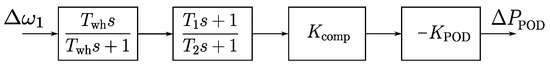
Figure 4.
POD control block diagram whose output is used by VSC1 and VSC3.
The POD power is supposed to be supplied from the rotating inertial of the wind turbines. This means that the net power extracted from a wind turbine over one period of onshore interarea oscillation is zero. Therefore, adding the POD control on the OWF does not require any changes on the limits of the primary reserved power.
In the POD block diagram shown in Figure 4, is the time constant of the washout filter. The filter with and is used for phase regulation (to make the input and output of the POD controller in exact opposite phase) and compensates a gain reduction that is caused by the filters. is the POD gain which is determined based on the desired damping coefficient, and also regarding the amount of power deviation, , which can be tolerated by the OWF.
5. Simulation Studies
Simulations of the system considered in Section 2 are presented in this section. Simulations have been implemented in MATLAB/Simulink to analyze the results in both time and frequency domain. It is assumed that the OWF generates 800 MW power and has 50 MW extra capacity for the primary reserve. 500 MW of OWF’s power flows to onshore System 1, and 300 MW to System 2 under steady state condition. Modular multilevel converters (MMCs) are used for the HVDC converters. The MMC model used simulations is an average model of half-bridge type converter with 200 submodules per arm. Power/voltage and inner-current controllers of the converters are modeled with full details. Each onshore grid is modeled as an aggregated synchronous machine equipped with prime mover, governor, and AVR. Moreover, passive loads are connected to the generators via transformer and AC lines. The model used for synchronous generators has field and damper windings on its d-axis and two damper winding on its q-axis. The prime movers of the generators are of hydro-turbine governing system.
A load disturbance of 100 MW is considered in onshore System 1 to create a frequency event in the system. The primary support is assumed to be supplied by a local governor, with a frequency droop of 0.06 per-unit, and HVDC control with a frequency droop of 0.08 per-unit. The overall time constant of the turbine-governor is 2 s. The communication delay of 20 ms is considered in simulations. The ramp-rate of OWF’s active power change is 0.1 pu/s (or 100 MW/s) and that of HVDC converters is 2 pu/s (or 2000 MW/s). The other important parameters of AC system and HVDC control are presented in Table 1.

Table 1.
AC system and HVDC control parameters.
Simulations are conducted for both AFC and CFC under three different case studies as described in the following.
- Case A:
- the reserve capacity of OWF is 50 MW, and power deviation of VSC2 can be 50 MW to participate in frequency control.
- Case B:
- the reserve capacity of OWF is 15 MW, and power deviation of VSC2 can be 50 MW to participate in frequency control.
- Case C:
- the reserve capacity of OWF is 15 MW, and power deviation of VSC2 can be 15 MW to participate in frequency control.
The simulation results, showing , , and , are presented in Figure 5 and Figure 6 when using AFC from the offshore HVDC. From plot, it is shown that the damping of the interarea oscillations is improved if the oscillations can be observed by the OWF and/or VSC2. In the Case C where the power is limited in both OWF and VSC2, the onshore oscillations are not observed and no damping is provided by the frequency control, although the steady state of frequency has been improved by 15 MW extra power from the OWF. To realize more about the impact of primary frequency control of offshore HVDC on interarea oscillations damping, the eigenvalues of the system are plotted in Figure 7. The gain of the frequency control, , is increased from 12.5 to 17.5 per-unit, which results in increasing the damping coefficient of interarea mode, i.e., shifts more to left hand side on the s-plane. Plotting the eigenvalues in Figure 7, it is assumed that there is no power limitation on the OWF and HVDC converters.
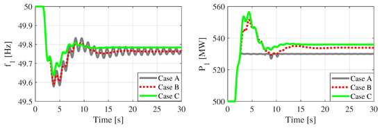
Figure 5.
Onshore frequency, , and power fed by VSC1, , when using AFC from offshore HVDC.
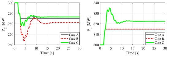
Figure 6.
Power fed from VSC2, , and generated power by the OWF, , when using AFC from offshore HVDC.
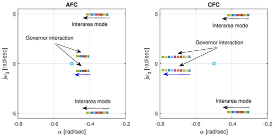
Figure 7.
The zeros and poles of the system where is increased from 12.5 to 17.5 per-unit. The plots are zoomed in to clearly show the changes of eigenvalues related to interarea mode. ’x’ and ’o’ respectively indicate poles and zeros of the system.
The same scenarios are implemented using CFC. The simulation results are shown in Figure 8 and Figure 9. Compared to AFC, in the Case A the frequency drop has been improved better with CFC in steady state. This is because more power—in comparison to AFC—is imported from the OWF to onshore systems using CFC. However, in Case B and C the results from CFC are almost the same as those from AFC. In terms of damping the interarea modes, not much difference is observed. To make better comparison of damping effectiveness, the dominant eigenvalues of the system when using CFC are also shown in Figure 7. The damping effects of both CFC and AFC on interarea modes are almost the same. However, the modes related to governor interactions are improved more with CFC because more power is imported to onshore systems and frequency reaches steady state faster, meaning the turbine-governor oscillation—which is very slow—is damped faster.
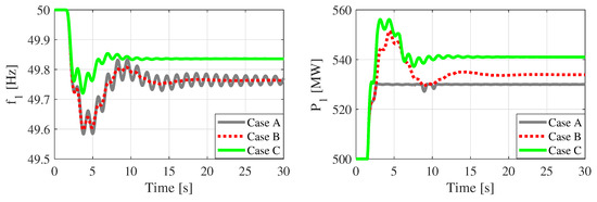
Figure 8.
Onshore frequency, , and power fed by VSC1, , when using CFC from offshore HVDC.
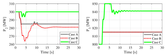
Figure 9.
Power fed from VSC2, , and generated power by the OWF, , when using CFC from offshore HVDC.
Simulating the POD functionality, it is supposed the primary reserve of the OWF is limited and VSC2 has also a limited power change, similar to those of Case C. The POD simulation results are shown in Figure 10 and Figure 11. It is shown that using the POD control, the onshore oscillations are observed by the OWF and VSC2 which contribute in onshore POD control. It is obvious in Figure 11 that very slight variation in and can result in significant damping of onshore system oscillations which is shown in plot in Figure 10. The damping improvement by the POD control can be better shown by the complex-conjugate eigenvalues related to interarea modes that are presented in Figure 12.
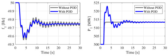
Figure 10.
Onshore frequency, , and power fed by VSC1, , when using AFC (Case C) in parallel with a POD control.
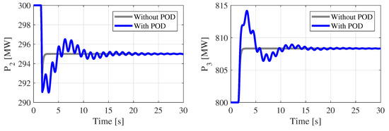
Figure 11.
Power fed from VSC2, , and generated power by the OWF, , when using AFC (Case C) in parallel with a POD control.
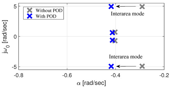
Figure 12.
Eigenvalues of the system with AFC (Case C) in parallel with a POD control. The shift of eigenvalues is because of the POD control.
6. Conclusions
The impact of primary frequency control of offshore HVDC grids on interarea modes of onshore AC systems was analytically investigated. The damping coefficients were derived as functions of HVDC controller parameters as well as electro-mechanical dynamic parameters. It is concluded that although a communication-less frequency control cannot meet the system operator’s requirements in terms of supplying their expected power in response to onshore frequency drop, it is useful in sharing oscillation damping between onshore AC grids. It was shown that the resulting damping could be affected by power limits of the wind farm or HVDC converters, and thereby, using power oscillation damping control is suggested.
Author Contributions
Conceptualization, methodology: A.B., O.S.-R., P.E.S., N.A.C.; Supervision: P.E.S., N.A.C., V.A.; Writing—review & editing: A.B., O.S.-R., N.A.C.; Data curation, formal analysis, investigation, project administration, software, validation, visualization, writing—original draft: A.B.
Funding
This work has received funding from the European Union’s Horizon 2020 research and innovation program under grant agreement No 691714.
Conflicts of Interest
The authors declare no conflict of interest. The funders had no role in the design of the study; in the collection, analyses, or interpretation of data; in the writing of the manuscript, or in the decision to publish the results.
References
- Sorknæs, P.; Andersen, A.N.; Tang, J.; Strøm, S. Market integration of wind power in electricity system balancing. Energy Strategy Rev. 2013, 1, 174–180. [Google Scholar] [CrossRef]
- WindVision; Enercon; Eneco; Elia. Delivery of Downward aFRR by Wind Farms. Available online: https://www.google.com.hk/url?sa=t&rct=j&q=&esrc=s&source=web&cd=1&ved=2ahUKEwjUhLjY05rlAhVHxosBHTcIDhEQFjAAegQIARAC&url=https%3A%2F%2Fimages.engineeringnet.eu%2FRSS%2Fimages%2FReport_%2520Downward_aFRR_windfarms_2015.pdf&usg=AOvVaw1W8VFAyigTV_3lNIB0sqZj (accessed on 4 September 2019).
- Phulpin, Y. Communication-Free Inertia and Frequency Control for Wind Generators Connected by an HVDC-Link. IEEE Trans. Power Syst. 2012, 27, 1136–1137. [Google Scholar] [CrossRef]
- Silva, B.; Moreira, C.L.; Seca, L.; Phulpin, Y.; Peças-Lopes, J.A. Provision of Inertial and Primary Frequency Control Services Using Offshore Multiterminal HVDC Networks. IEEE Trans. Sustain. Energy 2012, 3, 800–808. [Google Scholar] [CrossRef]
- Akkari, S.; Dai, J.; Petit, M.; Guillaud, X. Interaction between the voltage-droop and the frequency-droop control for multi-terminal HVDC systems. IET Gener. Transm. Distrib. 2016, 10, 1345–1352. [Google Scholar] [CrossRef]
- Sakamuri, J.N.; Altin, M.; Hansen, A.D.; Cutululis, N.A. Coordinated frequency control from offshore wind power plants connected to multi terminal DC system considering wind speed variation. IET Renew. Power Gener. 2017, 11, 1226–1236. [Google Scholar] [CrossRef]
- Adeuyi, O.D.; Cheah-Mane, M.; Liang, J.; Jenkins, N. Fast Frequency Response from Offshore Multi-terminal VSC-HVDC Schemes. IEEE Trans. Power Deliv. 2017, 32, 2442–2452. [Google Scholar] [CrossRef]
- Haileselassie, T.M.; Uhlen, K. Primary Frequency Control of Remote Grids Connected by Multi-terminal HVDC. In Proceedings of the IEEE PES General Meeting, Providence, RI, USA, 25–29 July 2010. [Google Scholar]
- Zhu, J.; Guerrero, J.M.; Booth, C.D.; Zhang, H.; Adam, G.P. A generic Inertia Emulation Controller for multi-terminal VSC-HVDC systems. In Proceedings of the 2nd IET Renewable Power Generation Conference (RPG 2013), Beijing, China, 9–11 September 2013; pp. 1–6. [Google Scholar]
- Bidadfar, A.; Saborío-Romano, O.; Müfit, A.; Cutululis, N.A.; Eduardo, P.A.; Oriol, G.B.; Sørensen, P. Droop-Based Frequency Support from Offshore HVDC Grids. In Proceedings of the Cigre Aalborg 2019: International Symposium, Aalborg, Denmark, 4–7 June 2019. [Google Scholar]
- Bidadfar, A.; Saborío-Romano, O.; Sakamuri, J.N.; Müfit, A.; Cutululis, N.A.; Sørensen, P. Primary Frequency Support from Offshore Wind Power Plants Connected to HVDC Grids. In Proceedings of the 2019 IEEE Milan PowerTech, Milan, Italy, 23–27 June 2019; pp. 1–6. [Google Scholar]
- Harnefors, L.; Johansson, N.; Zhang, L. Impact on Interarea Modes of Fast HVDC Primary Frequency Control. IEEE Trans. Power Syst. 2017, 32, 1350–1358. [Google Scholar]
- Chaudhuri, N.R.; Majumder, R.; Chaudhuri, B. System Frequency Support Through Multi-Terminal DC (MTDC) Grids. IEEE Trans. Power Syst. 2013, 28, 347–356. [Google Scholar] [CrossRef]
- Domínguez-García, J.L.; Gomis-Bellmunt, O.; Bianchi, F.D.; Sumper, A. Power oscillation damping supported by wind power: A review. Renew. Sustain. Energy Rev. 2012, 16, 4994–5006. [Google Scholar] [CrossRef]
- Knüppel, T.; Nielsen, J.N.; Jensen, K.H.; Dixon, A.; Østergaard, J. Power oscillation damping capabilities of wind power plant with full converter wind turbines considering its distributed and modular characteristics. IET Renew. Power Gener. 2013, 7, 431–442. [Google Scholar] [CrossRef]
- Domínguez-García, J.L.; Ugalde-Loo, C.E.; Bianchi, F.D.; Gomis-Bellmunt, O. Input–output signal selection for damping of power system oscillations using wind power plants. Electr. Power Energy Syst. 2014, 58, 75–84. [Google Scholar] [CrossRef]
- Zeni, L.; Eriksson, R.; Goumalatsos, S.; Altin, M.; Sørensen, P.; Hansen, A.D.; Kjær, P.; Hesselbæk, B. Power Oscillation Damping From VSC–HVDC Connected Offshore Wind Power Plants. IEEE Trans. Power Deliv. 2016, 31, 829–838. [Google Scholar] [CrossRef]
- Pipelzadeh, Y.; Chaudhuri, N.R.; Chaudhuri, B.; Green, T.C. Coordinated Control of Offshore Wind Farm and Onshore HVDC Converter for Effective Power Oscillation Damping. IEEE Trans. Power Syst. 2017, 32, 1860–1872. [Google Scholar] [CrossRef]
- Saborío-Romano, O.; Bidadfar, A.; Göksu, Ö.; Zeni, L.; Cutululis, N.A. Power Oscillation Damping from Offshore Wind Farms Connected to HVDC via Diode Rectifiers. Energies 2019, 12, 3387. [Google Scholar] [CrossRef]
- Muljadi, E.; Pasupulati, S.; Ellis, A.; Kosterov, D. Method of Equivalencing for a Large Wind Power Plant with Multiple Turbine Representation. In Proceedings of the 2008 IEEE Power and Energy Society General Meeting–Conversion and Delivery of Electrical Energy in the 21st Century, Pittsburgh, PA, USA, 20–24 July 2008. [Google Scholar]
- Chaudhuri, N.R.; Chaudhuri, B.; Majumder, R.; Yazdani, A. Multi-Terminal Direct-Current Grids, 1st ed.; Wiley-IEEE Press: Piscataway, NJ, USA, 2014; p. 256. [Google Scholar]
- Modeling of multi-terminal vsc hvdc systems with distributed dc voltage control. IEEE Transa. Power Syst. 2014, 29, 34–42. [CrossRef]
- Kundur, P. Power System Stability and Control; McGraw-Hill, Inc.: New York, NY, USA, 1994. [Google Scholar]
© 2019 by the authors. Licensee MDPI, Basel, Switzerland. This article is an open access article distributed under the terms and conditions of the Creative Commons Attribution (CC BY) license (http://creativecommons.org/licenses/by/4.0/).