Article

Optimization of Air Distribution to Reduce NOx Emission and Unburned Carbon for the Retrofit of a 500 MWe Tangential-Firing Coal Boiler

1
School of Mechanical Engineering, Sungkyunkwan University, Suwon 16419, Korea
2
Doosan Heavy Industries and Construction, Youngin 16858, Korea
*
Author to whom correspondence should be addressed.
Energies 2019, 12(17), 3281; https://doi.org/10.3390/en12173281
Submission received: 18 July 2019 / Revised: 12 August 2019 / Accepted: 23 August 2019 / Published: 26 August 2019
(This article belongs to the Special Issue Advances in Combustion of Gases, Liquid Fuels, Coal and Biomass)

Abstract

:
The use of separated overfire air (SOFA) has become a standard technique of air staging for NOx reduction in the coal-fired boiler and can also be applied to existing boilers by retrofit. This study was to optimize the air distribution for the proposed SOFA installation in a 500 MWe tangential-firing boiler that has 20 identical units in Korea. Using computational fluid dynamics (CFD) incorporating advanced coal combustion submodels, the reference case was established in good agreement with the design data, and different flow ratios of burner secondary air, close-coupled OFA (CCOFA), and SOFA were evaluated. Increasing the total OFA ratio effectively suppressed NO formation within the burner zone but had a negative impact on the boiler performance. With moderate air staging, NO reduction became active between the CCOFA and SOFA levels and, therefore, the OFA distribution could be optimized for the overall boiler performance. For total OFA ratios of 25% and 30% with respective burner zone stoichiometric ratios of 0.847 and 0.791, increasing the SOFA ratio to 15% and 20%, respectively, was ideal for decreasing the unburned carbon release and ash slagging as well as NO emission. Too high or low SOFA ratios rapidly increased the unburned carbon because of inefficient mixing between the strong air jets and char particles. Based on these ideal cases, the actual air distribution can be adjusted depending on the coal properties such as the ash slagging propensity.

Graphical Abstract

1. Introduction

NOx emission from coal-fired power plants has become a crucial issue in the power industry in Korea because of its contribution to the formation of secondary particulate matter of less than 2.5 µm (PM2.5) by photochemical reactions. Due to climate change in the Korean Peninsula and the increase of inbound pollutants, severe haze events have become frequent in recent years [1,2]. The contribution of secondary PM originating from coal-fired power plants is yet to be clarified among the inbound and domestic sources. However, air quality concern has a negative impact on the public perception of coal power and has changed energy policy including the temporary shutdown of old plants, as well as more stringent emission regulations. Although advanced combustion technology and efficient gas cleaning equipment are already in use, further lowering the pollutant emission from existing power plants to the minimum has become a most urgent issue. This applies to existing power plants, which include 20 units of 500 MWe tangential-firing (TF) boilers in Korea that have been built since 1993 with an identical design and are referred to as the ‘standard’ 500 MWe unit.
NOx emission reduction has been a key topic of combustion and gas cleaning technology. As the primary measure, the formation of NOx needs to be minimized by a combination of air staging, fuel staging, and low-NOx burners [3]. NOx can then be removed by secondary measures such as selective catalytic or non-catalytic reduction. In particular, NOx emission from coal is dominated by the fuel NOx mechanism, and therefore optimizing the reaction stoichiometry by air staging is very effective for its reduction. One advanced technique of air staging is the use of separated overfire air (SOFA) injected distantly above the burner zone. It is differentiated from close-coupled OFA (CCOFA) which is injected immediately above the top burners in a TF boiler. Adjusting the CCOFA ratio can be helpful in reducing NOx [4], but multi-level air staging by the use of SOFA can provide increased retention time for the reduction reactions to be more effective. The SOFA technique can also be applied to the 20 standard TF boilers in Korea by retrofit.
Together with NO emission, furnace exit gas temperature (FEGT) and unburned carbon (UBC) in ash are the key performance parameters of boiler operation associated with the operability and efficiency [5]. Various studies of the optimization of SOFA to improve boiler performance have been reported in the literature based on experiments and/or computational fluid dynamics (CFD). Increasing the SOFA ratio and optimizing its detailed distribution were found to be effective in reducing NOx emission for various boiler types [6,7,8,9,10,11,12,13]. However, the change in reaction stoichiometry can also significantly alter the combustion and heat transfer characteristics. In the study of Zha et al. [9] in a 600 MWe TF boiler, increasing the SOFA ratio from 10% to 40% achieved 50% reduction in NOx emission with more uniform heat flux distribution. However, this accompanied an unfavorable increase in the UBC in the fly ash, in the CO concentration, and in the flue gas temperature at the platen superheater, together with a significant change in the heat absorption pattern between the wall and convective heat exchangers. Li et al. [14] performed experiments on various damper openings of secondary air (SA) in the burner zone, CCOFA, and SOFA for a retrofitted 300 MWe TF boiler, and found that an ideal setup reduced the NOx emission by 44% with the UBC in ash not influenced at a sacrifice in boiler efficiency of 0.21%. The aerodynamics of SOFA also has a large influence on the UBC and heat absorption pattern in the heat exchangers downstream and adjusting the yaw and tilt angles of SOFA can alleviate such problems [15,16,17]. The reducing atmosphere in the burner zone by increasing the SOFA ratio may increase the possibility of fireside corrosion by H2S. In this respect, the experimental study of Xu et al. [18] reported that the air distribution can be adjusted to reach a balance between low corrosion, low NOx emission, and high boiler efficiency.
This study was to optimize the flow rate distribution of CCOFA and SOFA for NOx reduction in the standard 500 MWe TF boiler to be retrofitted including the installation of SOFA. Different ratios of flow rates between the burner secondary air, CCOFA, and SOFA were simulated. The CFD method was validated using the design data for the reference case of the retrofit boiler. From the results, the boiler performance was evaluated to determine the ideal flow ratios, and to understand the reasons for the differences in terms of NOx emission, UBC in ash, furnace exit gas temperature (FEGT), heat transfer rates, boiler efficiency, and the possibility of high-temperature corrosion.

2. Target Boilers and Numerical Methods

2.1. Target Boiler and Operation Conditions

Figure 1 shows a schematic of the 500 MWe coal-fired TF boiler modified from its original design. The modification was intended to adjust the operation range to low-rank coals and to improve its efficiency with an increased steam temperature from 538 °C to 596 °C. Because the original boiler only had CCOFA for air staging, SOFA was to be installed for the efficient reduction of NOx emission. This retrofit was also expected to extend its lifetime by ten years. The burner zone had six levels of coal burners (A to F levels) installed on the corners to create a swirling flow (fireball) at the center. It was divided into three sections with two burners each having an identical arrangement of coal and air supply ports as illustrated in the figure. Each coal burner aerodynamically split the coal and primary air flow into concentrated and weak ports depending on the coal concentration. The CCOFA was injected through four ports immediately above the top burner F on each corner. In the retrofit design, the SOFA was located 6.144 m above the CCOFA with two ports on each corner and one each on the adjacent side walls. The convective heat exchangers in the upper part had a new arrangement consisting of superheaters (SH) and reheaters (RH) with different tube bank geometry and steam conditions. An economizer (ECO) was located in the backpass. The furnace was built with membrane tube walls that act as an evaporator of the preheated water from the ECO. The new steam pressure and temperature leaving the final SH to the high-pressure turbine were 255.4 kg/cm2g and 596 °C, respectively.
Table 1 presents the characteristics of the performance coal and summary of the operating conditions. The coal for the retrofit boiler was sub-bituminous with a higher heating value (HHV) of 5600 kcal/kg which was significantly lower than that for the old design coal (6300 kcal/kg). At the nominal rate load, the coal throughput was 55.583 kg/s which delivered 1303 MWth of thermal input on an HHV basis. The coal was pulverized to an average particle size of 50 μm, and partially dried by hot primary air to have a moisture content of 8.6% and a mass flow rate of 50.494 kg/s. It was transported by the primary air (including the evaporated moisture) from the pulverizers to the burners A to E. The secondary air (SA) with a total flow rate of 355.1 kg/s at 326 °C was distributed into different ports of the burner SA, CCOFA, and SOFA. The overall excess air ratio was 12.94%.
Table 2 summarizes the simulation cases for various distributions of CCOFA and SOFA. In the first set of cases, the SOFA ratio was increased from 15% to 35%, while fixing the CCOFA ratio at 5%. These values corresponded to the burner zone stoichiometric ratio (SR) of 0.904 to 0.678. In the second set, the distribution between CCOFA and SOFA was varied from 0% to 25% by 5% increments, while fixing the total OFA ratio at 25%. Each case was named after the ratio in the two OFA ports. For example, C05-S20 refers to the case with 5% CCOFA ratio and 20% SOFA ratio. This is the reference case to be used for validation of the CFD results by comparison with the design data.

2.2. CFD Modeling

The mesh was constructed for the boiler using 3,529,358 cells. This mesh was selected after assessing the sensitivity by comparing the degree of numerical diffusion between coarser (1.23 million cells) and finer (5.47 million cells) meshes. In these meshes, the cell fineness was varied only in the burner zone to have a respective average volume of 0.0114, 0.0034, and 0.0022 m3/cell. Compared to the finer mesh, the selected one exhibited very small deviations in the key performance parameters (0.12% in carbon conversion, 1.9% in the exit NO concentration, and 0.2% in the heat absorption on the furnace wall). In the detailed comparison for the flow pattern along the vertical centerline, the deviations from the results of the finer mesh were 4.7% in the velocity profile and 0.71% in the temperature profile. By contrast, the coarser mesh had deviations of 17.58% and 1.11%, respectively. The computation time for the selected mesh to reach a converged solution was 69% of that for the finer mesh. The details of the mesh sensitivity test together with the iteration strategy have been reported elsewhere [19].
The CFD simulations were performed using ANSYS Fluent (version 17.2) [20] with submodels for reactions, turbulence, and radiation, most of which have been reviewed by Sankar et al. [5] as common models applied to a coal-fired boiler. The reaction submodels are summarized in Table 3. Coal particles were tracked using the discrete phase method for 10 size fractions ranging between 5.9 μm and 204 μm, with a total of 49,560 particles. FLASHCHAIN [21] was used to determine the input parameters for coal devolatilization in a drop tube furnace at 1200 °C which was close to the heat transfer condition of pulverized particles in the boiler. This code predicted the reaction dynamics based on the semi-empirical coal network mode to provide the product yields (tar, CO, CO2, H2O, CH4, C2H4, C2H6, C3H6, HCN, H2S, and solid char) and reaction kinetics as listed in the table. Because the heating rate was much faster than that in the proximate analysis, the total volatiles yield (58.56% daf) was larger than the volatile matter content (41.67% daf) in Table 1. Because of sharing the same mass source from devolatilization and having similar reaction rates, C2+ hydrocarbons were simplified to an imaginary species of CxHy. The yield and composition of tar were modified to include the H and O fractions of char so that the char could be modelled as a pure carbon solid and ash. For simplicity, it also incorporated the two minor volatiles (HCN and H2S). Char conversion by O2, CO2, and H2O was solved using the unreacted core shrinking model (UCSM) [22] which is suitable for high-temperature reactions in the industrial-scale furnace and the release of the UBC in fly ash. This model considers the three competing rates of the heterogeneous reaction on the char core surface and the gas diffusions onto the particle and through the ash layer. With the UCSM, the decrease in the reactivity toward the end of char conversion can be simulated, which was required to predict the UBC in fly ash. The multiple volatile products and the UCSM were implemented into the CFD code using user defined functions (UDF).
Gaseous reactions (R4)−(R10) were based on the global reaction scheme of Jones and Lindstedt [23] for hydrocarbon and the tar oxidation rate for (R4) was taken from Smoot and Smith [24]. In the reaction rate, the turbulence-chemistry interaction was considered using the kinetic rate/eddy dissipation rate model [25] with the realizable k-ε model employed for turbulence.
Regarding the heat transfer, radiation was solved using the discrete ordinate method with the weighted sum of the gray gases model for gas absorption [28]. In the boundary condition, the entire furnace wall (evaporator) was set to have the average water/steam temperature of 652.15 K with an overall heat transfer coefficient of 250 W/m2K and inner wall emissivity of 0.7. The heat transfer coefficient was taken as the average of measured values 3.51–4.37 m2K/kW of thermal resistance equivalent to 229–285 W/m2K depending on the coal types [29]. The tube bundles from primary SH to the economizer were simplified as porous zones, with local source terms calculated for flow resistance, convection, and radiation based on the detailed geometry and steam conditions [30]. In brief, the inertial resistance in the lateral and transverse directions was calculated using the Jakob correlation [31]:
Δ p = 2 f G m a x 2 N L ρ ( μ s μ ) 0.14
f = [ 0.044 + 0.08 ( S L D ) ( S T D 1 ) 0.43 + 1.13 D / S L ] R e 0.15
Similarly, the heat transfer rate in each cell was calculated as the sum of convection ( q ˙ c o n v ) and radiation ( q ˙ r a d ) for the specific tube surface area per unit volume (As):
q ˙ c o n v = f c o n v A s k   N u D ( T g a s T s )   [ W / m 3 ]
q ˙ r a d = f r a d ε σ A s ( T g a s 4 T s 4 )   [ W / m 3 ]
The Nusselt number (Nu) for convection was determined from the Zukauskas correlation [32]:
N u = 0.40 R e D 0.6 P r 0.36
The above equations include two correction factors (fconv and frad) that were introduced to consider the slagging/fouling factors and tuned to match the design values. The formulations for the flow resistance and heat transfer rates were implemented using UDFs.
NO reactions were calculated by post-processing of the CFD results. Thermal NO reactions were based on the extended Zeldovich mechanism with the rate constants taken from Hanson and Salimian [26] and the radical concentrations acquired from the respective partial equilibrium assumptions. In the fuel NO mechanism [27], the partitioning of fuel-N between volatile-N and char-N was determined using FLASHCHAIN. The release of N intermediates during the devolatilization of the low rank coal was assumed to be HCN 5:NH3 1, whereas the char-N was converted directly to NO. The reduction of NO to N2 on the active char surface was considered with a microscopic surface area that was assumed to be 100 m2/g. Prompt NO was ignored because its concentration is known to be minor [3].

3. Results

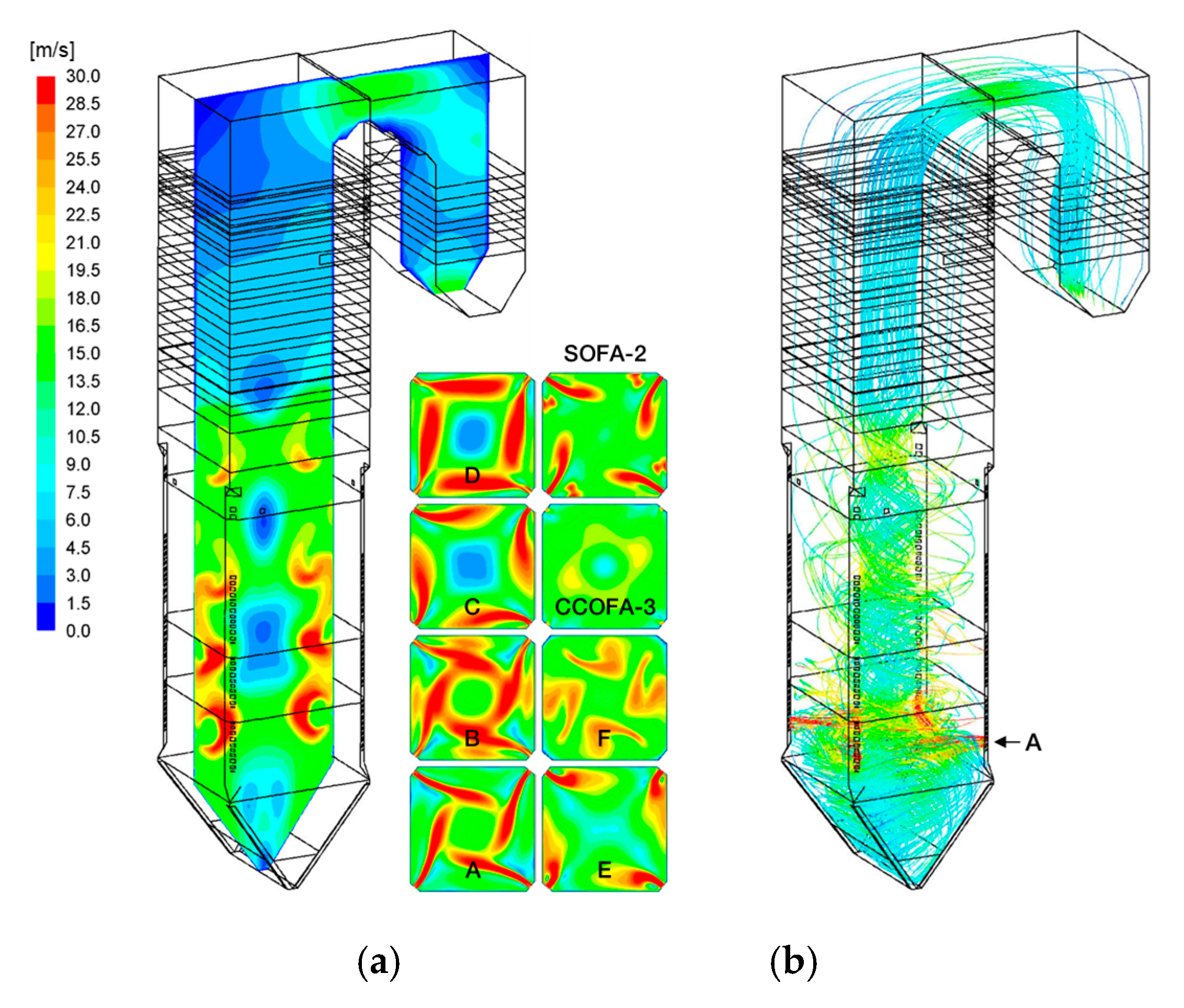
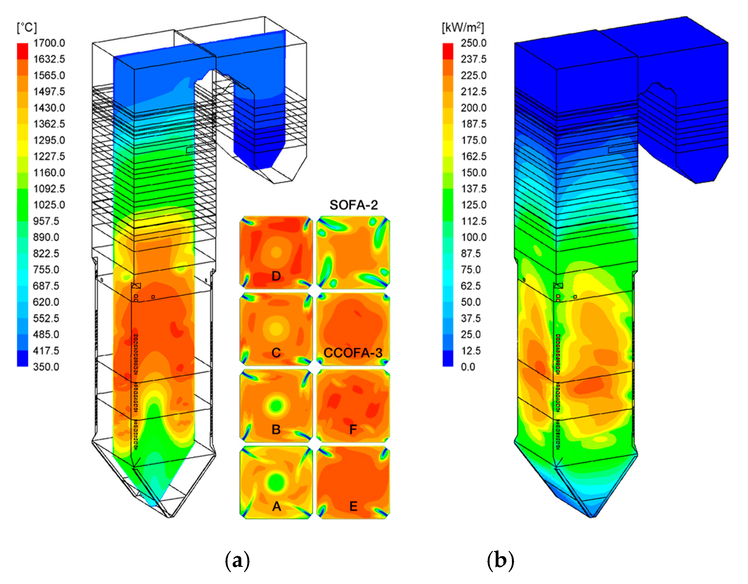
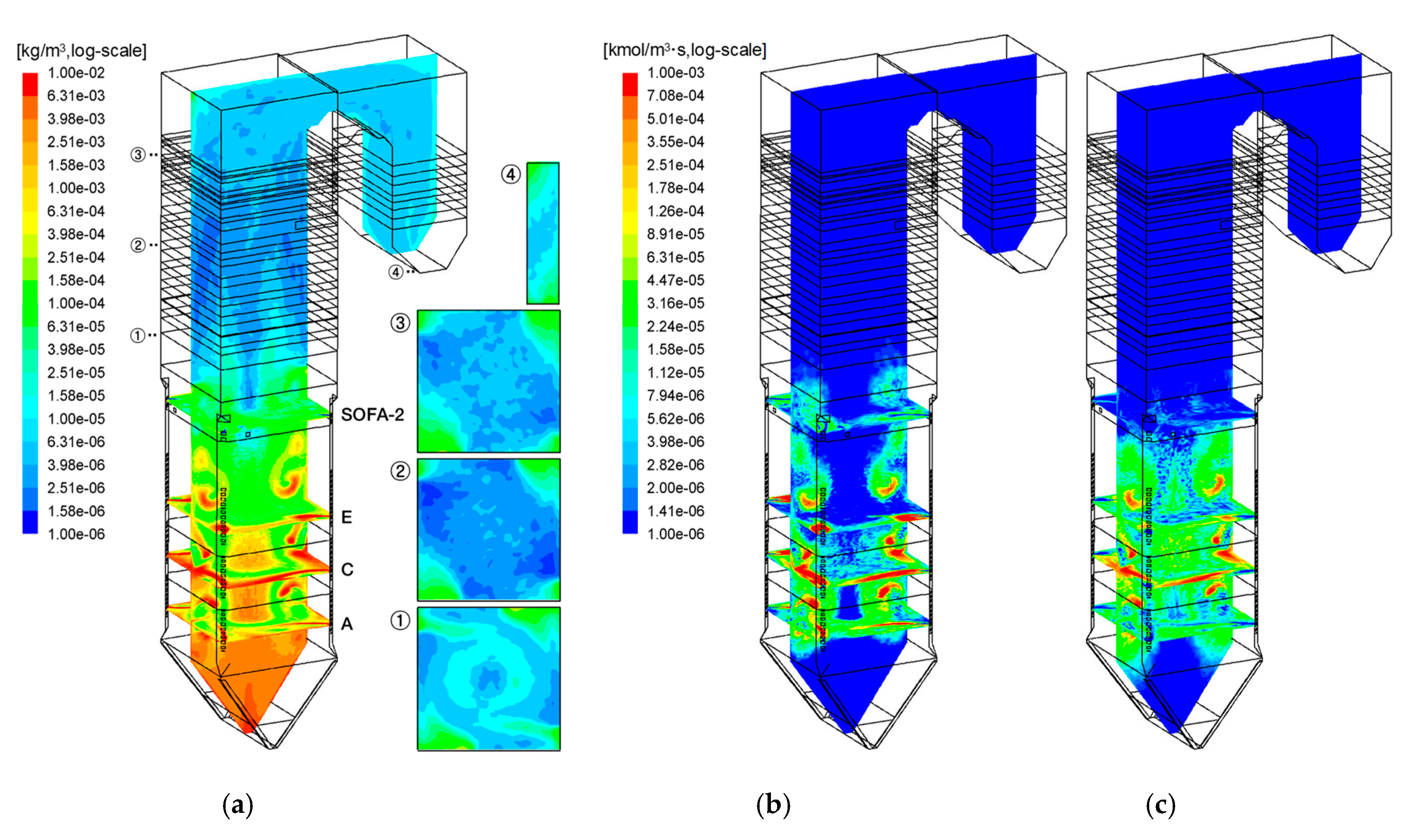
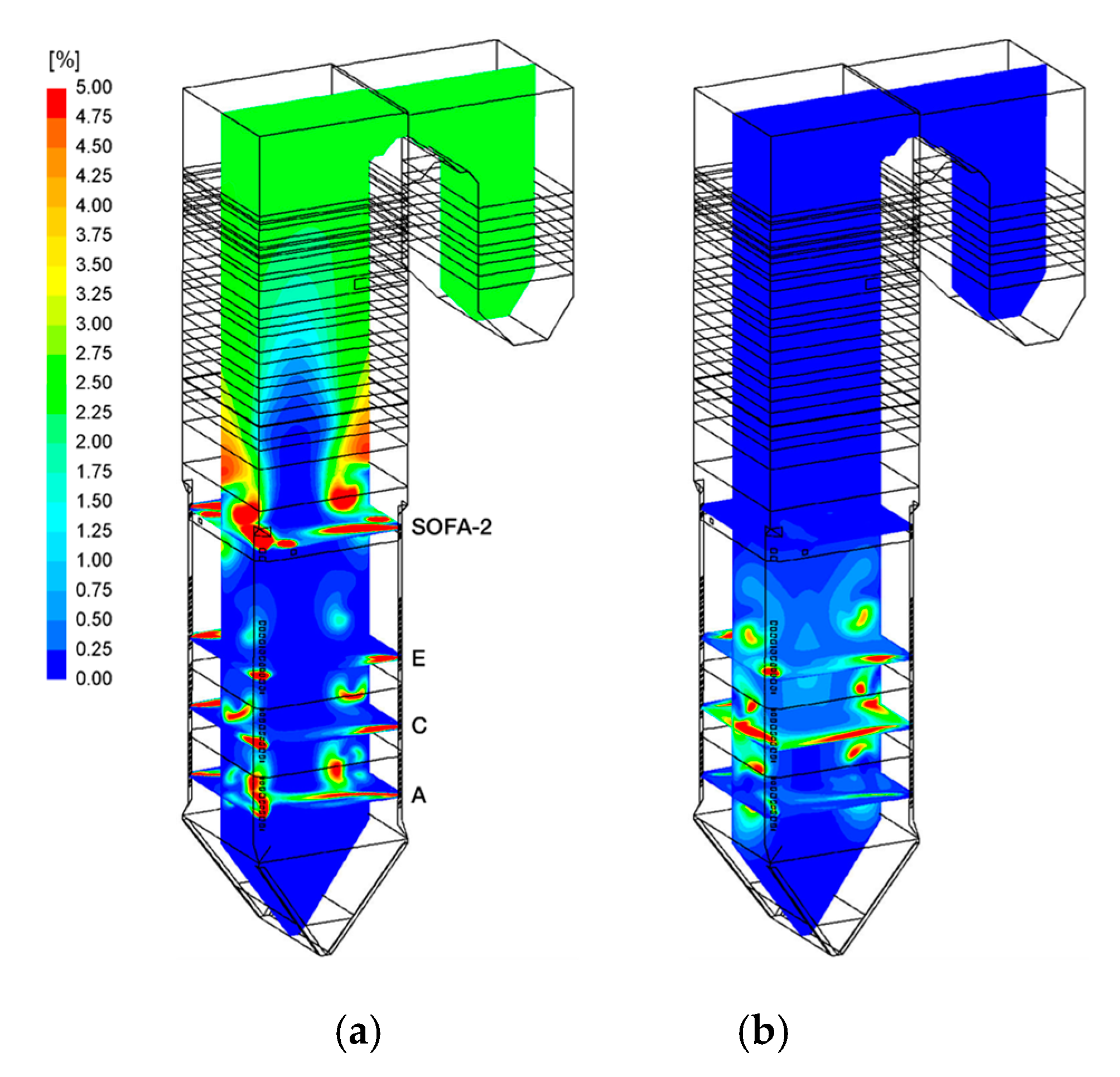
3.1. Reaction and Heat Transfer in the Reference Case

The key results for the reference case (C05-S20) are explained in this section to understand the flow, reaction, and heat transfer characteristics of the boiler before comparisons between the simulation cases varying the CCOFA and SOFA ratios. As shown in Figure 2, the flow and combustion patterns were characterized by the formation of a large swirling fireball across the burner zone which is typical for a TF boiler. The fireball was pushed to the center by the large momentum delivered by the jets from the burners on the corners, whereas it expanded towards the wall by the centrifugal force in the spacings between the burners B and C, and D and E. This created the crescent shapes of a high velocity region above 20 m/s in the vertical cross-section of Figure 2a. With the increase of flow rate from the burners A to E, the fireball size became larger. Above the SOFA, the fireball finally expanded, before the flow entered the tube bundles. The path-lines from the burner A in Figure 2b show that the flow from this burner filled the bottom section, and then moved upward through the center of the fireball. The jet flows from the other burners above joined the swirling flow of the fireball mostly at its outer part.
Figure 3a shows the temperature on the selected cross-sections and heat flux on the wall. The bottom cone region was filled with the flow from burner A and was cooled down to a low temperature by heat transfer to the wall. It then entered the center of the fireball, which created the bell-shaped low-temperature (<1000 °C) region in the lower furnace. The temperature gradually increased by introduction of more coal along the height to form the high-temperature zone above 1500 °C, which stretched from the near-wall region of the burner D level to the center at the SOFA level. The cold SOFA jets at 326 °C caused a temperature drop by dilution although it delivered additional air for burnout of the remaining char and combustible gases. The temperature decreased rapidly above the primary SH which virtually stopped further gaseous or heterogeneous reactions. The wall heat flux shown in Figure 3b was large in the burner zone with a peak of 220.6 W/m2 appearing on the burner D level which coincided with the temperature contours.
Figure 4 shows the solid carbon concentration and the rates of char conversion reactions. The solid carbon in char particles had high concentrations (>0.01 kg/m3) close to the wall caused by the inertia of the swirling flow. In addition, some char particles originating from the lowermost burners filled the bottom cone and then entered the center of the fireball from below with insufficient char conversion. Because the burner zone was fuel-rich (SR of 0.847), the solid carbon remained at the top of the burner zone. The CCOFA and SOFA delivered the rest of the air for char oxidation. Although the overall SR became fuel-lean, solid carbon was present in the heat exchanger zone because the mixing by the OFA jets was not perfect. In particular, unburned char particles were present mostly on the corners of cross-section (1) with a concentration over 5 × 10⁻⁵ kg/m3 in Figure 4a. On cross-section (2), the carbon concentration decreased along the SOFA paths to below 2 × 10⁻⁶ kg/m3 by slow oxidation but the corners still had concentrated char particles. Above this section, the temperature was not high enough for further char reactions, which led to the UBC in fly ash. The contour on the vertical cross-section in Figure 4a appears to have an increased carbon concentration in the top furnace because the mixing of the particles from the corners with the gas flow slowly progressed. Therefore, the trajectories of OFA jets and its mixing with the char particles are important in reducing the UBC before they enter the heat exchangers.
As shown in Figure 4b, the char oxidation reactions were active in the outer part of the fireball where most char particles were present, and the combustion air was delivered. However, no oxidation occurred in the bottom cone, at the center of the fireball, and above the primary SH, because the temperature was not high enough and/or O2 was depleted. Because the temperature was high enough in the burner zone, the gasification by CO2 and H2O also made a significant contribution to the char conversion (Figure 4c). Integrating the reaction rates over the entire volume, the two gasification reactions accounted for 36.7% of char conversion and the remainder by oxidation.
Figure 5a shows that O2 delivered by the burner SA was consumed rapidly and was depleted in most of the burner zone. By contrast, O2 from the SOFA penetrated deeper, because in this case, the SOFA ratio was relatively large (20%). The excess O2 then approached the wall as the fireball expanded. O2 was fully consumed at the central region above the SOFA to have a very low solid carbon concentration. After the flow entered the heat exchanger zones, the fireball quickly disappeared, and the mixing slowly progressed. The CO mole fraction above 5% appeared along the path of coal particles in the burner zone, as shown in Figure 5b. In particular, its concentration was very high on the sidewalls of burners C and D. The excessively reducing atmosphere can increase the possibility of high-temperature corrosion of the wall. Without further fuel supply, the CO mole fraction decreased rapidly by the CCOFA injection and became below 0.25% on the SOFA level. On the platen SH, the CO concentration was 46 ppm.
Figure 6 shows the reaction rate and concentration of NO. Along the trajectories of coal particles, the fast devolatilization with very high heating rate released the N-intermediates which were partially oxidized to produce NO under the oxygen-rich atmosphere with the PA and burner SA around. This was followed by char conversion releasing NO directly from char-N. This led to the regions of fast NO formation rates of over 1 × 10⁻⁶ kmol/m3.s, which coincided with those of high concentrations of solid carbon (Figure 4a) and O2 (Figure 5a). Outside these regions, however, O2 was depleted and the reducing atmosphere caused the removal of NO (negative reaction rates). In particular, rapid reduction reactions (<−1 × 10⁻⁶ kmol/m3.s) took place by the remaining N-intermediates and by char with the already produced NO in the region around the coal jets where O2 was depleted. Also, the volume between the CCOFA and SOFA provided the spaces for further reduction reactions of NO, mainly by residual char. Integrating the reaction rates, the NO emission was dominated by the fuel NO mechanism, and the contribution of the thermal NO mechanism was only approximately 10%.
Table 4 compares the design data and CFD results for the reference case. The difference of O2 concentration between by design and the CFD result was 0.02%, owing to the release of UBC in fly ash and bottom ash. The predicted NO concentration was below the guaranteed value. The predicted heat absorption on the furnace wall using the measured thermal resistance was very close to the design value with a deviation of 0.04 MWth. The heat absorption on the tube bundles calibrated using fconv and frad was reasonably close to the design values. These results also imply that the predicted temperature distribution along the furnace height would be reasonable. However, this study was for the proposed boiler retrofit and the modeling approach was not validated by experiments. Therefore, the focus was on the comparative evaluation of the key performance parameters between simulation cases.

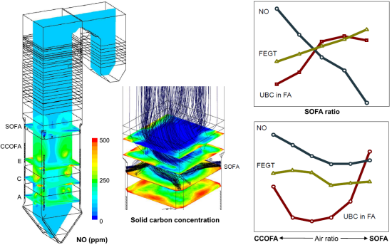
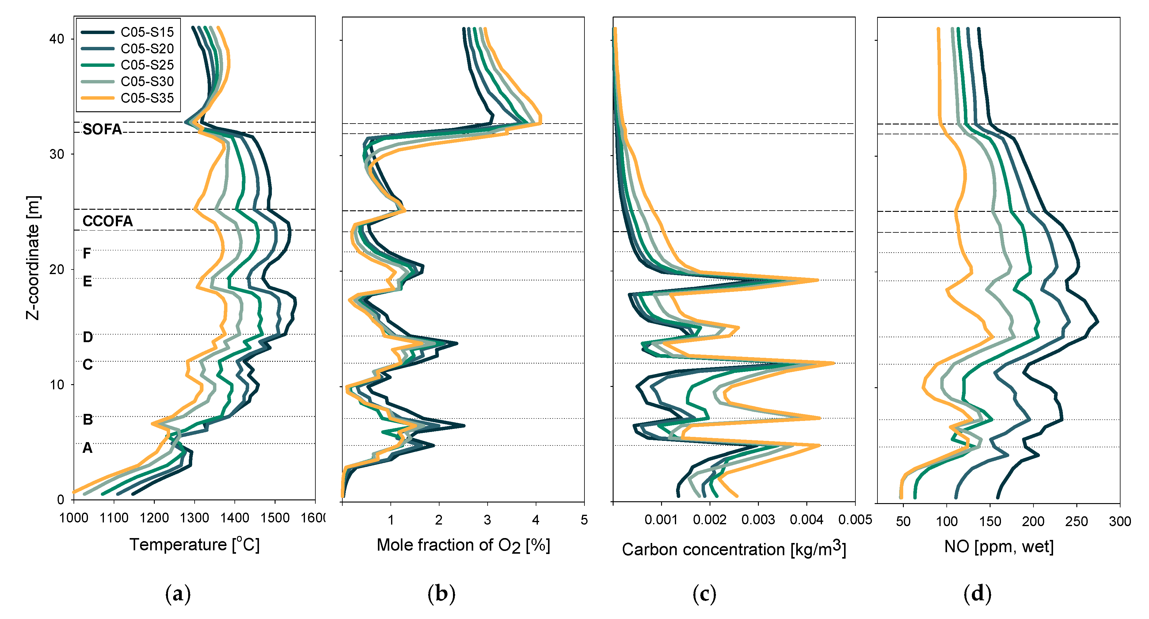
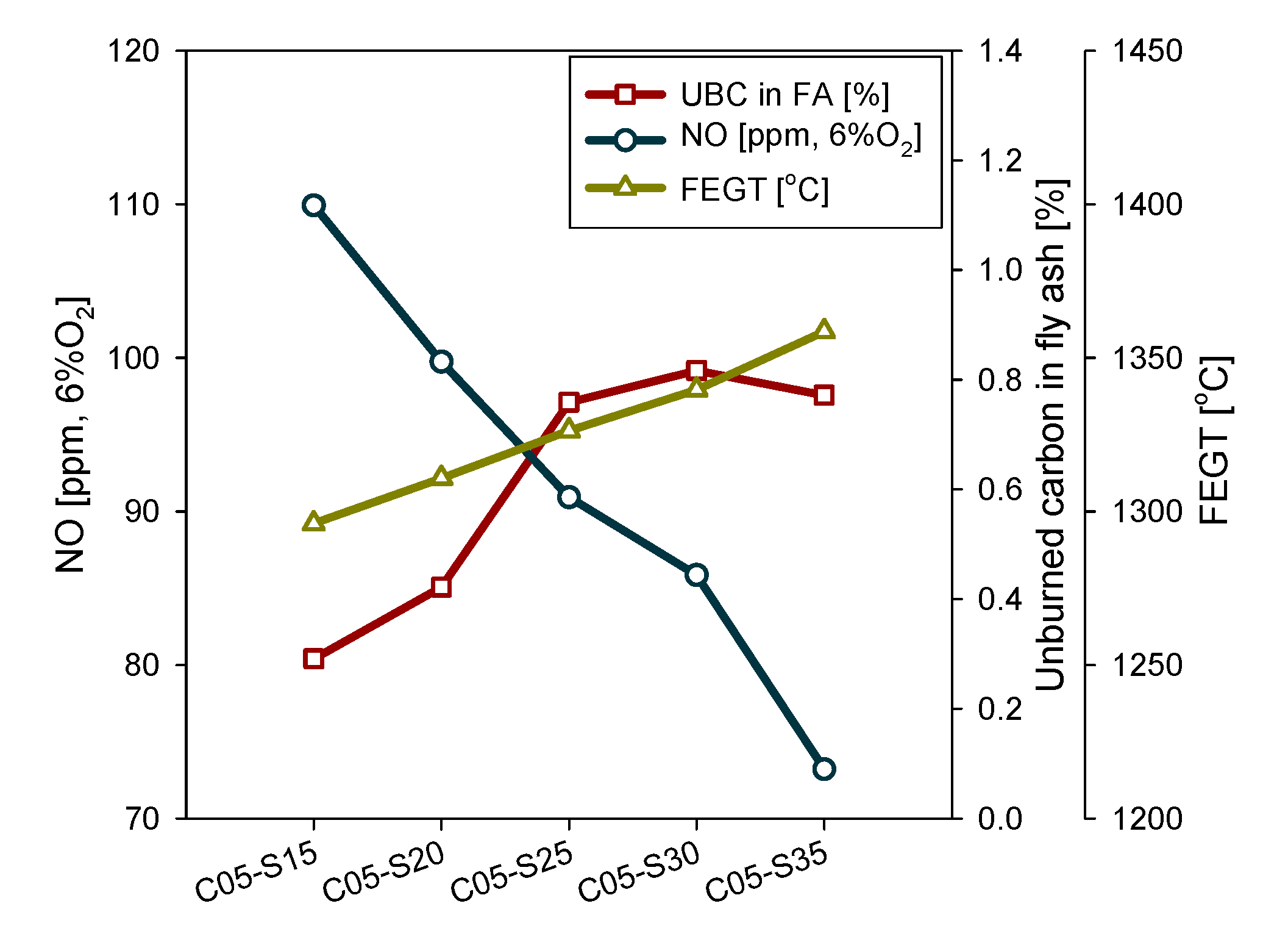
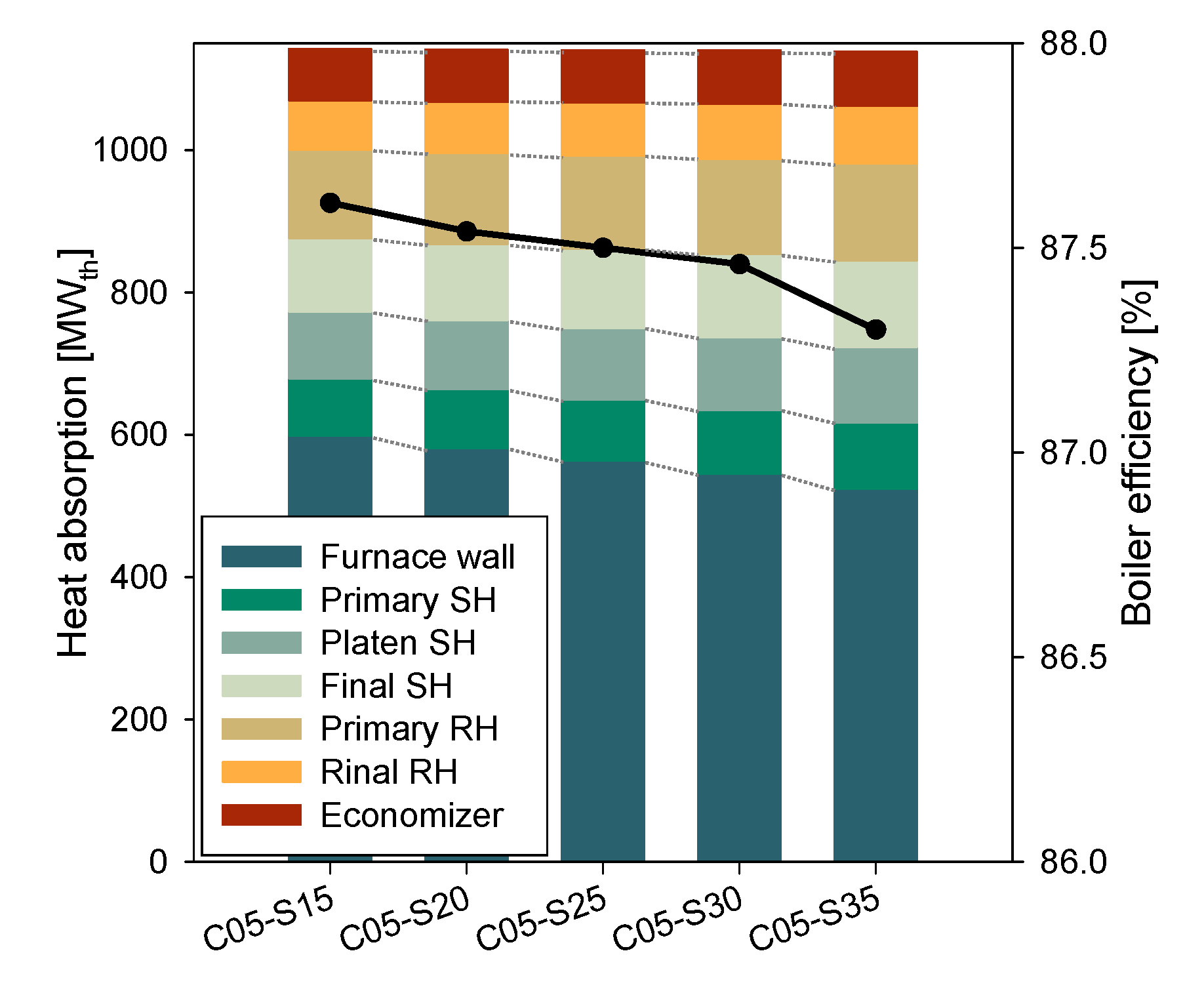
3.2. Influence of SOFA Ratios

Figure 7 compares the mass-weighted average profiles of temperature, O2, solid carbon, and NO concentrations for various SOFA ratios at a fixed CCOFA ratio of 5% and total OFA ratio of 25% (case set #1 in Table 1). In the burner zone, the temperature and O2 profiles were spread with a deviation of approximately 150 °C and 1%, respectively, with an increase in the SOFA ratio and corresponding decrease in the burner zone SR. The trends were inverted at the SOFA level by fast oxidation reactions of combustible gas species. The temperature profile influenced the distribution of heat absorption between the wall and tube bundles, which will be presented later. The carbon concentration exhibited acute changes responding to the fuel air supply from each coal burner in the burner zone. On the burner E, it varied from 0.00095 kg/m3 (C05-S15) to 0.00175 kg/m3 (C05-S35). With no further fuel supply above this level, it showed a continuous decrease to a value below 0.0001 kg/m3, with a final carbon conversion of 99.92% (C05-S15) and 99.80% (C05-S35). However, the differences between the cases in terms of UBC in fly ash were significant, which will be presented later.
In Figure 7d, the NO concentration sharply increased between the burners A–E, owing to the dominant contribution of fuel NO. Comparing the value between cases, both the thermal and fuel NO formations were suppressed at higher SOFA ratios having lower O2 concentration and temperature. In particular, NO reduction reactions were active in the region where O2 was locally depleted, as indicated by the decreases in the concentration between the burner levels of B and C, and D and E. On the burner F (standby) level where all the fuel has already been introduced, NO concentration was 128 ppm for C05-S35 and 251 ppm for C05-S15. However, between the volume between the F burner and the first SOFA ports, low SOFA ratios exhibited active NO reduction reactions which lowered the NO concentration to 181 ppm (−70 ppm from the value on the F level) for C05-S15. By contrast, NO concentration of C05-S35 on the first SOFA level was 110 ppm (−18 ppm). Then, the SOFA injection through the two port levels had an immediate dilution effect that further lowered the NO concentration to 151 ppm (−30 ppm) for C05-S15 and 93 ppm (−17 ppm) for C05-S35. Above the SOFA level, NO concentration was not significant. These results suggest that a high level of air staging is effective for low NO concentration within the burner zone and, therefore, the OFA distribution between the CCOFA and SOFA would not be crucial. However, for a moderate level of air staging, securing the volume (i.e., time) for NO reduction reactions is essential by the installation of SOFA and increasing its ratio larger than the CCOFA ratio.
Although large SOFA ratios effectively reduced NOx emission, negative impacts were accompanied on the boiler performance. Figure 8 shows the NOx emission and UBC in fly ash at the boiler exit and FEGT. FEGT was determined from the average gas temperature entering the first tube bundle (primary SH). The UBC represents the boiler efficiency, while the FEGT is associated with the propensity of ash slagging on the tube bundles. NOx emission was reduced from 109.9 ppm to 73.2 ppm (a 33.4% reduction) on a 6% O2 basis by the increase in the SOFA ratio, but the FEGT was increased by 62.6 °C, while the UBC was more than tripled. Therefore, the use of SOFA ratio as high as 35% was not favorable.
Figure 9 compares the heat absorption by heat exchangers for different SOFA ratios, which was closely associated with the temperature profile shown in Figure 7. On increasing the SOFA ratio, the heat absorption by the furnace wall was decreased from 599 MWth for C05-S15 to 524 MWth for C05-S35 by the lower gas temperatures of the burner zone. Because the trend in the temperature was inverted above the SOFA level, the heat absorption in the tube bundles of SHs, RHs, and ECO increased from a total of 543 MWth for C05-S15 to 614 MWth for C05-S35. The resultant boiler efficiency was 87.61%–87.30% on an HHV basis, which is also plotted in Figure 9. Together with the lower boiler efficiency, the increase in the SHs and RHs at the larger SOFA ratios has an unfavorable impact on the boiler operation. This is because it increases the possibility of high steam temperature at the final SH and RH exits that requires more water spray by the attemperator to maintain the value below the limit.
One additional issue to assess is the influence on corrosion of the water wall. With the increase in the OFA ratio, the burner zone SR decreased from 0.90 (C05-S15) to 0.68 (C05-S35). The more reducing environment in the furnace increases the possibility of high-temperature corrosion by the presence of H2S, COS, and CO [33], which shortens the lifetime of the boiler. As summarized in Table 5, the wall of the burner zone was exposed to more CO and less O2 with a decrease in the burner zone SR. Here, the CO concentration can directly represent the degree of reducing atmosphere. Using a CO mole fraction larger than 0.5% as the criterion of the strongly reducing atmosphere, the difference in each case was within 3% for the OFA ratio up to 30% (C05-S25). Above this value, the area increased rapidly. Therefore, an OFA ratio of 30% can be considered as the limit to avoid excessive corrosion, and 25% would be acceptable, considering the trade-off between NO emission and overall boiler performance.

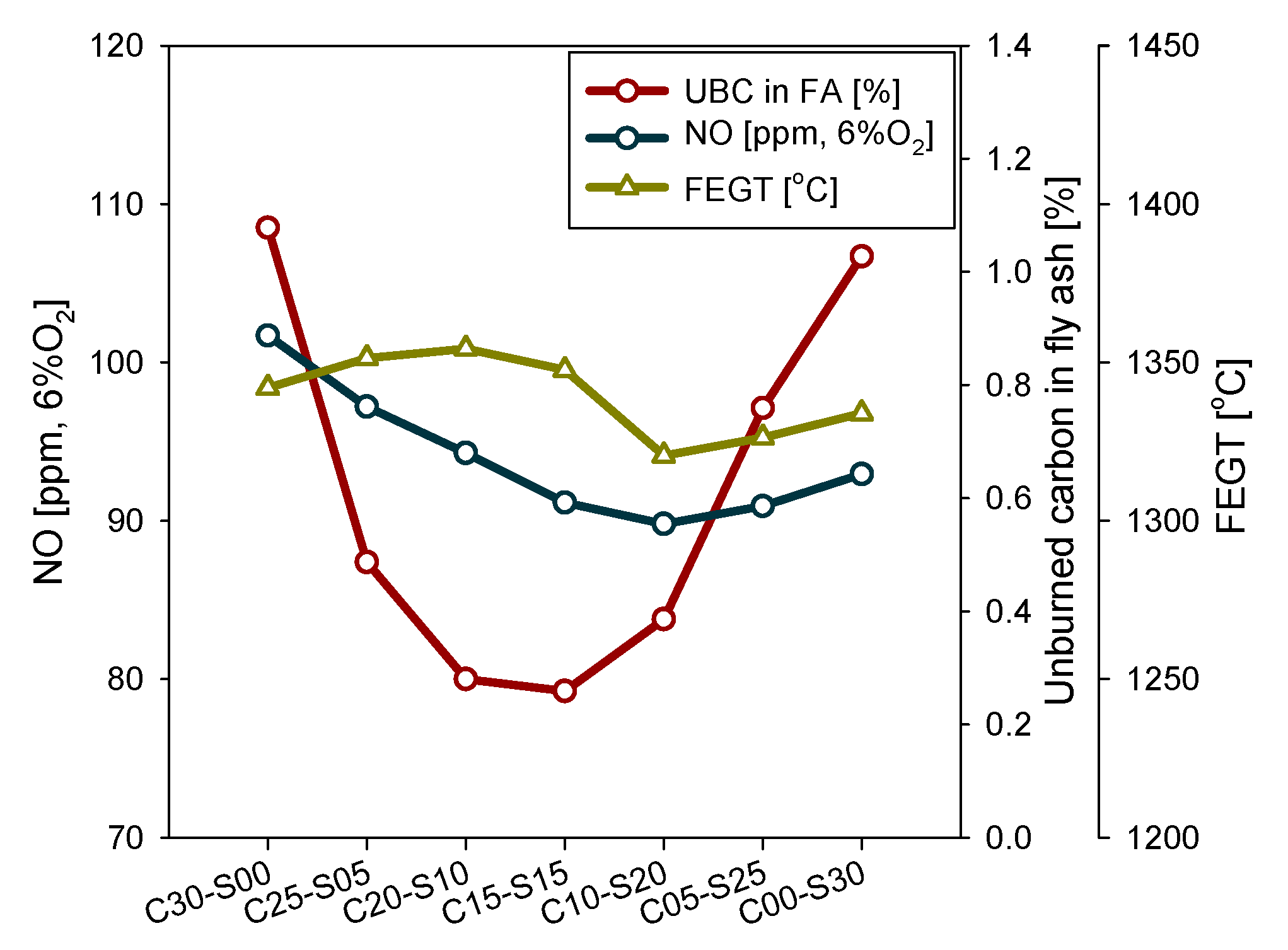
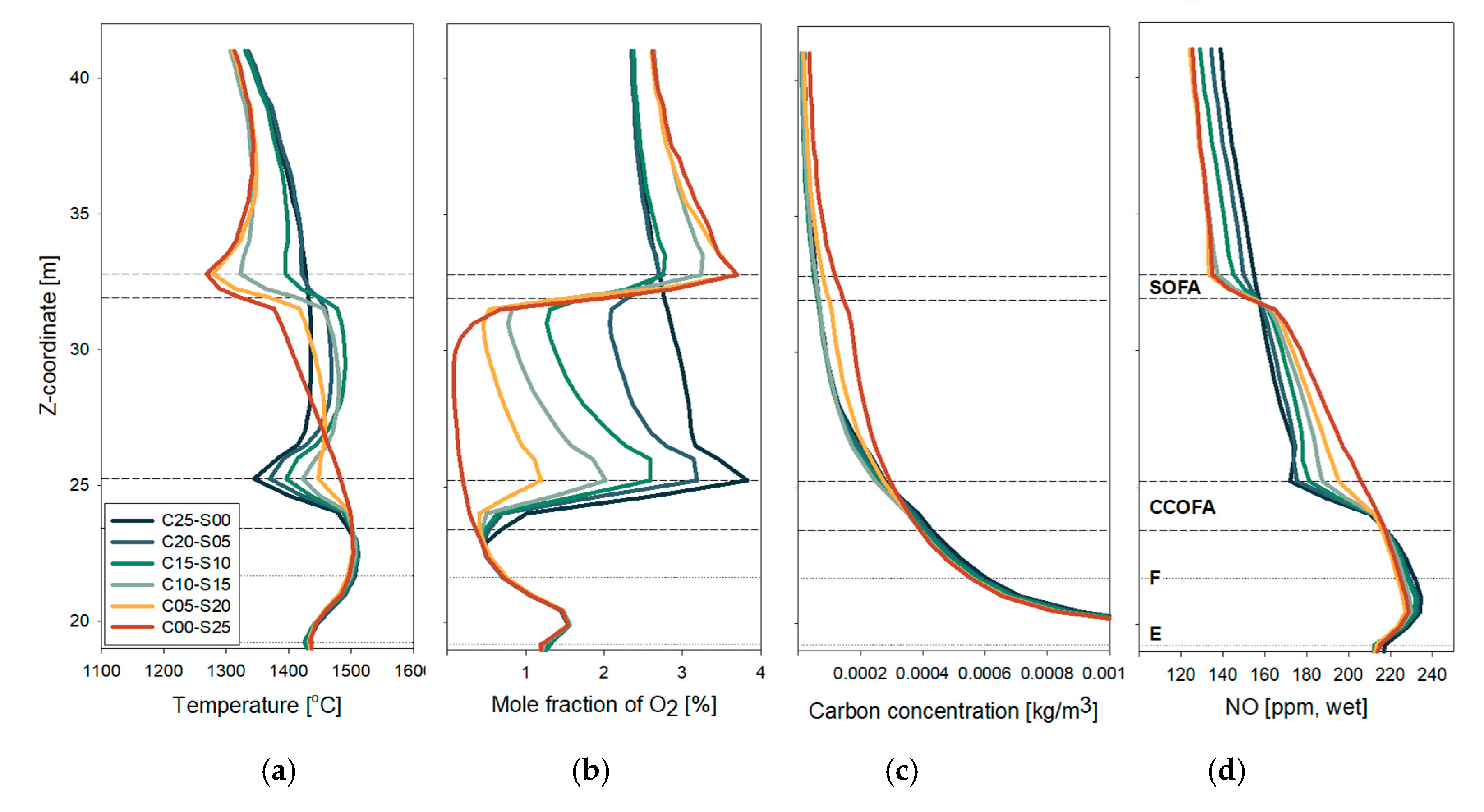
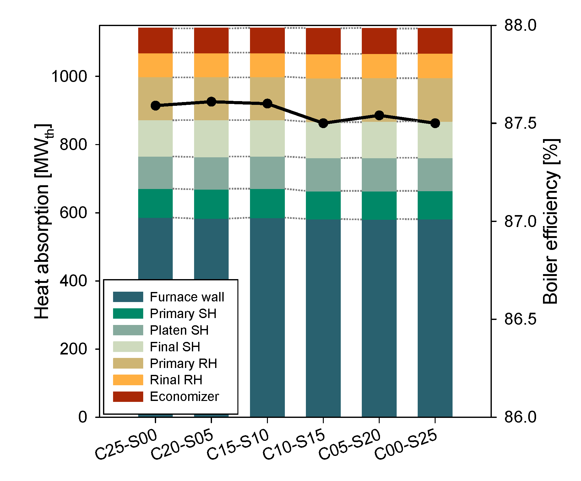
3.3. Influence of Different Air Distributions between SOFA and CCOFA

Figure 10 compares the profiles of gas temperature and concentrations narrowed to the region between burner E level and primary SH for different CCOFA/SOFA distributions with a total OFA ratio fixed at 25% (case set #2 in Table 1). Because the operation conditions of the burner zone were identical, the profiles below E level were the same as those of C05-S20 shown in Figure 7. High CCOFA ratios caused immediate temperature drops from approximately 1510 °C along the four ports, but the fresh air supply recovered the temperature more, by increased oxidation reactions above the CCOFA. It was followed by another temperature drop by the SOFA injection, but the temperature increase above the SOFA was noticeable only at higher SOFA ratios (C10-S15, C05-S20, and C00-S25). The solid carbon concentration above the CCOFA ports was higher for C00-S25 and C05-S20 due to the shortage of O2, but the rest of the cases had similar values. After the SOFA injection, C00-S25 exhibited more active decrease in solid carbon concentration but its rate was not as fast as those in the burner zone. This led to the highest UBC in the fly ash for this case.
In the NO profile, the CCOFA injection caused immediate decrease by dilution, splitting the values from 218 ppm on the lowermost CCOFA port level to a range between 174−210 ppm at the top CCOFA port level. The degree of NO reduction reaction in the volume between the CCOFA and SOFA depended on the O2 concentration, as indicated by the fact that the slope in the NO concentration was proportional to the SOFA ratio. This significantly reduced the difference in the NO concentration before the SOFA level. Then, the trend was almost inverted after the SOFA injection by dilution, but the values of C05-S20 and C00-S25 were similar to that for C10-S15. The NO reduction reactions slowly continued until the gas entered the primary SH and the temperature decreased rapidly.
Figure 11 compares the key performance parameters for different CCOFA/SOFA distributions in case set #2. The UBC content in fly ash, NO emission, and FEGT had favorable results by increasing the proportion of SOFA up to 15% for a total OFA ratio of 25%. Therefore, C10-S15 was the ideal case in this case set. Above this SOFA ratio, both NO emission and FEGT did not change noticeably. However, the UBC content increased rapidly. This was mainly because too strong jets of CCOFA or SOFA led to an inefficient mixing between the char particles and fresh oxygen. This can be confirmed from the path-lines shown in Figure 12 for CCOFA for C25-S00 and SOFA for C10-S15 and C00-S25 drawn on the contours of solid carbon concentration. In the lowermost cross-section, the char particles were present mainly near the wall by the centrifugal force of the fireball. The strong jets by the largest CCOFA or SOFA ratios (C25-S00 and C00-S25, respectively) penetrated deeper into the furnace, and the solid carbon concentration decreased rapidly along their trajectories. However, a significant fraction of char particles escaped the cross-sections through the spaces not covered by the OFA trajectories. In contrast, the jets of CCOFA and SOFA in C10-S15 had a moderate momentum that supplied fresh oxygen to the region near the wall where char particles were more concentrated. This explains the low UBC in this case. The quenching effect by the OFA jets appeared not to be significant, because in all cases, the entrained char was effectively converted. The heat absorption pattern and boiler efficiency were little influenced by the CCOFA/SOFA distribution, as shown in Figure 13.
Figure 14 compares the key performance parameters for different CCOFA/SOFA distributions in case set #3 with a total OFA ratio fixed to 30%. The trends in the parameters were similar with those in case set #2 shown in Figure 11, but the NO emissions were lower whereas the FEGT was higher. From the results, C10-S20 could be considered ideal at 30% OFA ratio. Compared to C10-S15 (ideal in case set #2 at 25% OFA ratio), the NO emission (90 ppm) was lowered by 10 ppm whereas the FEGT (1320 °C) and the UBC content (0.39%) were 14 °C and 0.14% higher, respectively.
Overall, the results indicate that the CCOFA/SOFA distribution for a fixed total OFA ratio can be optimized for improved boiler performance. Compared to the case with CCOFA only (C25-S00) before the retrofit of this boiler, the overall performance can be significantly enhanced in terms of the NOx emission, the FEGT, and the UBC content in fly ash. With the SOFA installation, cases C10-S15 and C10-S20 were ideal for the OFA ratios of 25% and 30%, respectively. The actual air distribution can be adjusted around these cases, depending on the fuel properties such as ash slagging propensity, fuel N and S contents, heating value, etc.

4. Conclusions

This study investigated the performance of a 500 MWe tangential-firing coal boiler for optimization of the air distribution with an installation of SOFA. Using CFD, the reference case was established in a good agreement with the design data and different air distributions were evaluated for key performance parameters. Increasing the SOFA ratio led to lower NO emission because the NO reduction reactions were more active within the burner zone. However, too large SOFA ratios caused negative impacts on the boiler performance and increased the propensity of slagging and corrosion. With a moderate level of air staging, the NO reduction was also active between the CCOFA and SOFA levels and, therefore, the OFA distribution could be optimized to achieve good boiler performance as well as a low NO emission. For total OFA ratios of 25% and 30% (the burner zone stoichiometric ratio of 0.847 and 0.791, respectively), increasing the SOFA ratio to 15% and 20%, respectively, was ideal for significant reduction in NOx, unburned carbon in fly ash, and furnace exit gas temperature, compared to the case with CCOFA alone before the retrofit. Too high SOFA or CCOFA ratios at the fixed OFA ratios rapidly increased the unburned carbon, because of insufficient mixing between the strong air jets penetrating deep into the center and char particles concentrated near the wall. The heat absorption pattern and boiler efficiency were not noticeably influenced by the distribution between CCOFA and SOFA.

Author Contributions

Mesh generation and tests, H.J. and H.A.; CFD simulations, H.J., K.K., and J.P.; boiler design data and validation of reference case, H.A. and Y.G.; writing—original draft preparation, H.J.; writing—review and editing, C.R.; funding acquisition and project administration, C.R.

Funding

This work was supported by the Korea Institute of Energy Technology Evaluation and Planning (KETEP) affiliated with the Ministry of Trade, Industry and Energy of the Korean Government (Contract No. 20181110200190).

Acknowledgments

The authors would like to thank Doosan Heavy Industries and Construction for their help and technical support.

Conflicts of Interest

The authors declare no conflict of interest.

Nomenclature

Symbols
APre-exponential factor [s−1]
AsSpecific tube surface area per unit volume [m2/m3]
dDiameter [cm]
DTube diameter [cm]
EActivation energy [kJ/kmol]
fCorrection factor
f’Friction factor
GMass velocity [kg/m2·s]
KeqChemical equilibrium constant
kReaction rate [g⋅cm−2⋅atm−1⋅s−1], Thermal conductivity [W/m·K]
NNumber of tube
NuNusselt number
PPressure [atm]
PrPrandtl number
ΔpPressure difference [atm]
q ˙ Volumetric heat sink [W/m3]
RUniversal gas constant, Reaction rate of char [g⋅cm−2⋅s−1]
ReReynolds number
SPitch [m]
TTemperature [K]
VVolatile matter [kg]
YChar core to particle diameter ratio
Greek Symbols
εPorosity of the ash layer, Emissivity
ρDensity [kg/m3]
μViscosity [kg/m·s]
σStefan-Boltzman constant (5.67 × 10⁻⁸ [W/m2·K4])
Subscripts
charUnreacted char core
convConvection
diffDiffusion rate
dashDiffusion rate in the ash-layer
gasGas
iIndex of gasification reaction
LLongitudinal
maxMaximum
oInitial
pParticle
radRadiation
sSurface
tTotal pressure
TTransverse

References

  1. Kim, H.C.; Kim, S.; Kim, B.-U.; Jin, C.-S.; Hong, S.; Park, R.; Son, S.-W.; Bae, C.; Bae, M.; Song, C.-K.; et al. Recent increase of surface particulate matter concentrations in the Seoul Metropolitan Area, Korea. Sci. Rep. 2017, 7, 4710. [Google Scholar] [CrossRef] [PubMed]
  2. Choi, J.; Park, R.J.; Lee, H.-M.; Lee, S.; Jo, D.S.; Jeong, J.I.; Henze, D.K.; Woo, J.-H.; Ban, S.-J.; Lee, M.-D.; et al. Impacts of local vs. trans-boundary emissions from different sectors on PM2.5 exposure in South Korea during the KORUS-AQ campaign. Atmos. Environ. 2019, 203, 196–205. [Google Scholar] [CrossRef]
  3. Nalbandian, H. NOx Control for Coal-Fired Plant; CCC/157; IEA Clean Coal Centre: London, UK, 2009. [Google Scholar]
  4. Kang, K.; Ryu, C. Numerical simulation on the effects of air staging for pulverized coal combustion in a tangential-firing boiler. Korean Chem. Eng. Res. 2017, 55, 548–555. [Google Scholar]
  5. Sankar, G.; Kumar, D.S.; Balasubramanian, K.S. Computational modeling of pulverized coal fired boilers–a review on the current position. Fuel 2019, 236, 643–665. [Google Scholar] [CrossRef]
  6. Zhou, H.; Mo, G.; Si, D.; Cen, K. Numerical simulation of the NOx emissions in a 1000 MW tangentially fired pulverized-coal boiler: Influence of the multi-group arrangement of the separated over fire air. Energy Fuels 2011, 25, 2004–2012. [Google Scholar] [CrossRef]
  7. Ma, L.; Fang, Q.Y.; Lv, D.Z.; Zhang, C.; Chen, Y.P.; Chen, G.; Duan, X.N.; Wang, X.H. Reducing NOx emissions for a 600 MWe down-fired pulverized-coal utility boiler by applying a novel combustion system. Environ. Sci. Technol. 2015, 49, 13040–13049. [Google Scholar] [CrossRef] [PubMed]
  8. Ma, L.; Fang, Q.; Tan, P.; Zhang, C.; Chen, G.; Lv, D.; Duan, X.; Chen, Y. Effect of the separated overfire air location on the combustion optimization and NOx reduction of a 600 MWe FW down-fired utility boiler with a novel combustion system. Appl. Energy 2016, 180, 104–115. [Google Scholar] [CrossRef]
  9. Zha, Q.; Li, D.; Wang, C.A.; Che, D. Numerical evaluation of heat transfer and NOx emissions under deep-air-staging conditions within a 600 MWe tangentially fired pulverized-coal boiler. Appl. Therm. Eng. 2017, 116, 170–181. [Google Scholar] [CrossRef]
  10. Qi, X.; Yang, M.; Zhang, Y. Numerical analysis of NOx production under the air staged combustion. Front. Heat Mass Transf. 2017, 8, 1–8. [Google Scholar]
  11. Zheng, Y.; Gao, X.; Sheng, C. Impact of co-firing lean coal on NOx emission of a large-scale pulverized coal-fired utility boiler during partial load operation. Korean J. Chem. Eng. 2017, 34, 1273–1280. [Google Scholar] [CrossRef]
  12. Stupar, G.; Tucaković, D.; Živanović, T.; Stevanović, Ž.; Belošević, S. Predicting effects of air staging application on existing coal-fired power steam boiler. Appl. Therm. Eng. 2019, 149, 665–677. [Google Scholar] [CrossRef]
  13. Yang, W.; Wang, B.; Lei, S.; Wang, K.; Chen, T.; Song, Z.; Ma, C.; Zhou, Y.; Sun, L. Combustion optimization and NOx reduction of a 600 MWe downfired boiler by rearrangement of swirl burner and introduction of separated over-fire air. J. Clean Prod. 2019, 210, 1120–1130. [Google Scholar] [CrossRef]
  14. Li, S.; Xu, T.; Hui, S.; Wei, X. NOx emission and thermal efficiency of a 300 MWe utility boiler retrofitted by air staging. Appl. Energy 2009, 86, 1797–1803. [Google Scholar] [CrossRef]
  15. Wu, X.; Fan, W.; Liu, Y.; Bian, B. Numerical simulation research on the unique thermal deviation in a 1000 MW tower type boiler. Energy 2019, 173, 1006–1020. [Google Scholar] [CrossRef]
  16. Liu, Y.C.; Fan, W.D.; Wu, M.Z. Experimental and numerical studies on the gas velocity deviation in a 600 MWe tangentially fired boiler. Appl. Therm. Eng. 2017, 110, 553–563. [Google Scholar] [CrossRef]
  17. Park, H.Y.; Baek, S.H.; Kim, H.H.; Kim, Y.J.; Kim, T.H.; Lim, H.S.; Kang, D.S. Reduction of main steam temperature deviation in a tangentially coal-fired, two pass boiler. Fuel 2016, 166, 509–516. [Google Scholar] [CrossRef]
  18. Xu, L.; Huang, Y.; Zou, L.; Yue, J.; Wang, J.; Liu, C.; Liu, L.; Dong, L. Experimental research of mitigation strategy for high-temperature corrosion of waterwall fireside in a 630 MWe tangentially fired utility boiler based on combustion adjustments. Fuel Process. Tech. 2019, 188, 1–15. [Google Scholar] [CrossRef]
  19. Jo, H.; Kang, K.; Park, J.; Ryu, C.; Ahn, H.; Go, Y. Detailed assessment of mesh sensitivity and coupled iteration method for CFD simulation of coal combustion in a tangential-firing boiler. J. Mech. Sci. Technol. 2019. under review. [Google Scholar]
  20. ANSYS Inc. ANSYS Fluent User Guide; ANSYS Inc.: Cannonsburg, PA, USA, 2016. [Google Scholar]
  21. Niksa, S. PC Coal Lab Version 4.1: User Guide and Tutorial; Niksa Energy Associates LLC: Belmont, CA, USA, 1997. [Google Scholar]
  22. Wen, C.Y.; Chaung, T.Z. Entrainment coal Gasification Modeling. Ind. Eng. Chem. Process Des. Dev. 1979, 18, 684–695. [Google Scholar] [CrossRef]
  23. Jones, W.P.; Lindstedt, R.P. Global reaction schemes for hydrocarbon combustion. Combust. Flame 1988, 73, 233–249. [Google Scholar] [CrossRef]
  24. Smoot, L.D.; Smith, P.J. Coal Combustion and Gasification; Plenum Press: New York, NY, USA, 1985. [Google Scholar]
  25. Magnussen, B.F.; Hjertager, B.H. On mathematical models of turbulent combustion with special emphasis on soot formation and combustion. Proc. Combust. Inst. 1977, 16, 719–729. [Google Scholar] [CrossRef]
  26. Hanson, R.K.; Salimian, S. Survey of rate constants in H/N/O systems. In Combustion Chemistry; Gardiner, W.C., Ed.; Springer: New York, NY, USA, 1984; p. 361. [Google Scholar]
  27. De Soete, G.G. Overall reaction rates of NO and N2 formation from fuel nitrogen. Proc. Combust. Inst. 1975, 15, 1093–1102. [Google Scholar] [CrossRef]
  28. Smith, T.F.; Shen, Z.F.; Friedman, J.N. Evaluation of coefficients for the weighted sum of gray gases model. J. Heat Transf. 1982, 104, 602–608. [Google Scholar] [CrossRef]
  29. Park, H.Y.; Lee, J.E.; Kim, H.H.; Park, S.; Beak, S.H.; Ye, I.; Ryu, C. Thermal resistance by slagging and its relationship with ash properties for six coal blends in a commercial coal-fired boiler. Fuel 2019, 235, 1377–1386. [Google Scholar] [CrossRef]
  30. Park, J.K.; Park, S.; Kim, M.K.; Ryu, C.; Baek, S.H.; Kim, Y.J.; Kim, H.H.; Park, H.Y. CFD analysis of combustion characteristics for fuel switching to bioliquid in oil-fired power plant. Fuel 2015, 159, 324–333. [Google Scholar] [CrossRef]
  31. Jakob, M. Heat transfer and flow resistance in cross flow of gases over tube banks. Trans. ASME 1938, 60, 384–386. [Google Scholar]
  32. Zukauskas, A. Heat transfer from tubes in cross flow. In Advances in Heat Transfer; Hartnett, J.P., Irvine, T.F., Jr., Eds.; Academic Press: New York, NY, USA, 1972; Volume 8, pp. 93–160. [Google Scholar]
  33. Kung, S.C. Further understanding of furnace wall corrosion in coal-fired boilers. Corrosion 2014, 70, 749–763. [Google Scholar] [CrossRef]
Figure 1. Schematic of the 500 MWe coal-fired tangential-firing (TF) boiler.
Energies 12 03281 g001
Figure 2. Velocity contours and path-line from burner A for the reference case (C05-S20) (a) Velocity and (b) Path-line.
Energies 12 03281 g002
Figure 3. Temperature and wall heat flux for the reference case (C05-S20). (a) Temperature and (b) Wall heat flux.
Energies 12 03281 g003
Figure 4. Solid carbon concentration and char conversion rates for the reference (C05-S20). (a) Solid carbon concentration; (b) Char-O2 rate and (c) Char-CO2 rate.
Energies 12 03281 g004
Figure 5. Mole fractions of O2 and CO for the reference case (C05-S20). (a) O2 mole fraction and (b) CO mole fraction.
Energies 12 03281 g005
Figure 6. Reaction rate and concentration of NO for the reference case (C05-S20). (a) NO rate and (b) NO concentration.
Energies 12 03281 g006
Figure 7. Mass-weighted average profiles of gas temperature and concentrations of O2, solid carbon, and NO in the burner zone for different SOFA ratios (CCOFA ratio fixed at 5%). (a) Temperature; (b) O2; (c) Solid carbon and (d) NO.
Energies 12 03281 g007
Figure 8. Comparison of NOx emission, unburned carbon (UBC) in fly ash, and furnace exit gas temperature (FEGT) for different SOFA ratios (CCOFA ratio fixed at 5%).
Energies 12 03281 g008
Figure 9. Comparison of heat absorption by heat exchangers and boiler efficiency for different SOFA ratios (CCOFA ratio fixed at 5%).
Energies 12 03281 g009
Figure 10. Mass-weighted average profiles of gas temperature and concentrations of O2, solid carbon, and NO between E burner level and primary superheater for different CCOFA/SOFA distribution (total OFA ratio fixed at 25%). (a) Temperature; (b) O2; (c) Solid carbon and (d) NO.
Energies 12 03281 g010
Figure 11. Comparison of NOx emission, UBC in fly ash, and FEGT for different CCOFA/SOFA distributions (total OFA ratio fixed at 25%).
Energies 12 03281 g011
Figure 12. Solid carbon concentration and path-lines of CCOFA (foe C25-S00) and SOFA (for C10-S15 and C00-S25).
Energies 12 03281 g012
Figure 13. Comparison of heat absorption by heat exchangers and boiler efficiency for different CCOFA/SOFA distributions (total OFA ratio fixed at 25%).
Energies 12 03281 g013
Figure 14. Comparison of NOx emission, UBC in fly ash, and FEGT for different CCOFA/SOFA distributions (total OFA ratio fixed at 30%).
Energies 12 03281 g014
Table 1. Operating conditions of the 500 MWe coal-fired boiler.
InputValues
Coal propertiesProximate analysis (% wet): Total moisture 17, volatile matter 31.36, fixed carbon 43.89, ash 7.75
Ultimate analysis (% daf): C 76.95, H 5.34, O 16.01, N 1.19, S 0.51
Higher heating value (HHV): 5600 kcal/kg
Coal throughput55.583 kg/s (50.494 kg/s after drying/pulverization)
Primary air121.2 kg/s, 224 °C (126.3 kg/s, 77 °C after drying/pulverization)
Total secondary air355.1 kg/s, 326 °C
Excess air ratio12.94%
Table 2. Cases of various close-coupled overfire air (CCOFA) and separated overfire air (SOFA) ratios for computational fluid dynamics (CFD) simulations.
Case SetCase NameRatio in Total Combustion Air (%)Burner Zone SRNote
CCOFASOFATotal OFA
Set #1C05-S15515 200.904
C05-S20 20 250.847 Reference case
C05-S25 25 300.791
C05-S30 30 350.734
C05-S35 35 400.678
Set #2C25-S00250250.847
C20-S05205
C15-S101510
C10-S151015
C05-S20520 Reference case
C00-S25025
Set #3C30-S00300300.791
C25-S05255
C20-S102010
C15-S151515
C10-S201020
C05-S25525
C00-S30025
Table 3. Summary of submodels adopted for boiler simulation.
CategorySubmodels
Coal combustion-Devolatilization: FLASHCHAIN [21]
Dry coal→58.56 wt% daf Volatiles + 32.91 wt% daf C(s)(Char)
  Composition of Volatiles: Tar 32.57, CO 3.31, CO2 3.89, H2O 14.35, H2 0.71,
  CH4 1.99, CxHy 1.73 wt% daf
  Devolatilization rate:
   d V d t = A   exp ( E R T ) ( V 0 V ) ; E = 5.49 kcal/mol, A = 7.89 × 10³ s−1
-Char combustion: Unreacted core shrinking model [22]
     R c h a r , i = 1 1 k d i f f , i + 1 k s , i Y 2 + 1 k d a s h , i ( 1 Y 1 ) ( P i P i * ) [ g   cm 2   s 1 ]
     k d a s h = k d i f f ε 2.5 , Y = d c h a r / d p
(R1) C(s) + 0.5 O2 → CO
   k s = 8710 exp ( 17967 / T s ) ,   k d i f f = 1.383 × 10 3 ( T 1800 ) 0.75 / ( P t d p )
   P i P i * = P O 2
(R2) C(s) + H2O → CO+H2
   k s = 247 exp ( 21060 / T s ) ,   k d i f f = 1 × 10 3 ( T 2000 ) 0.75 / ( P t d p )
   P i P i * = P H 2 O ( P H 2 P C O ) / K e q ,   K e q = exp [ 17.644 30260 / ( 1.8 T s ) ]
(R3) C(s) + CO2 → 2 CO
   k s = 247 exp ( 21060 / T s ) ,   k d i f f = 7.45 × 10 4 ( T 2000 ) 0.75 / ( P t d p )
   P i P i * = P C O 2
Species, gas reaction-Species: Tar, CO, CO2, H2, CH4, CxHy, H2, SO2, O2, N2
-Reaction mechanism [23,24]
  (R4) CxHyOz (tar) + a O2 → x CO + 0.5y H2
  (R5) CnHm + 0.5n O2 → n CO + 0.5m H2
  (R6) CnHm + 0.5n H2O → n CO + 0.5(m+n) H2
  (R7) CH4 + 0.5 O2 → CO + 2 H2
  (R8) CH4 + 0.5 H2O → CO + 2.5 H2
  (R9) CO + H2O → CO2 + H2
  (R10)H2 + 0.5 O2 → H2O
-Reaction rate: kinetic rate/eddy dissipation rate model [25]
Discrete phase-Lagrangian scheme with stochastic tracking for turbulence
-Number of particles: 49,560
-Particle size: 5.88–204 μm
NOx-Thermal NOx: Extended Zeldovich mechanism [26]
-Fuel NOx: De Soete [27]
-Fuel-N intermediate: HCN 83.33%, NH3 16.67%
Table 4. Comparison of design data and CFD results for the reference case.
ParameterDesignCFD
Exit O2 (% dry)2.452.47
Exit NO (ppm, 6% O2)<15099.75
Heat absorptionFurnace wall562.31562.27
(MWth)Primary SH88.7484.00
Platen SH102.8199.96
Final SH113.04108.75
Primary RH128.86129.59
Final RH75.3671.05
Economizer72.9273.29
Table 5. Average mole fractions of CO and O2 and the area with CO > 0.5% on the wall of the burner zone.
CaseC05-S15C05-S20C05-S25C05-S30C05-S35
Mole fraction on the burner zone wall [%]CO0.3290.3550.4620.6090.704
O20.7830.6570.6170.6570.572
Wall area with CO > 0.5% in the burner zone16.018.721.935.542.1

