Power Control Method for Energy Efficient Buffer-Aided Relay Systems


Abstract
:1. Introduction
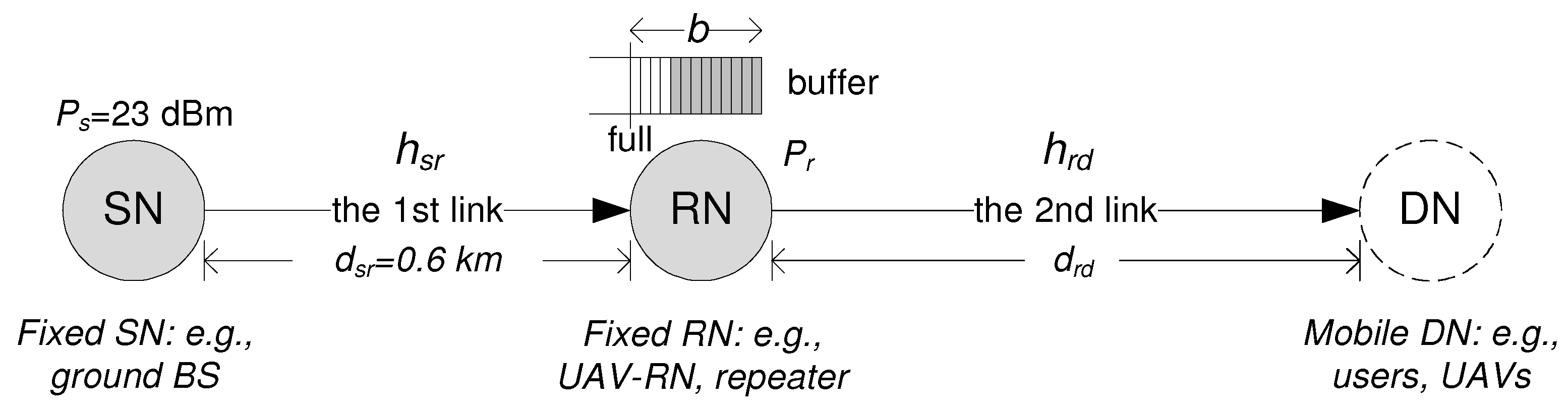
2. RN System Model
3. Achievable Rate of RN with a Buffer
- : RN forwards and reserves the remaining bits, i.e., bits, at the buffer unless the buffer is full with b bits. Thus, the buffer status at time t will be , where .
- : RN forwards . In this case, since RN can forward more bits up to , the number of forwarded bits will be . Accordingly, the buffer status will be .
4. Buffer Size Design
5. Proposed Power Control Method for Energy Efficient RN
6. Numerical Results and Discussion
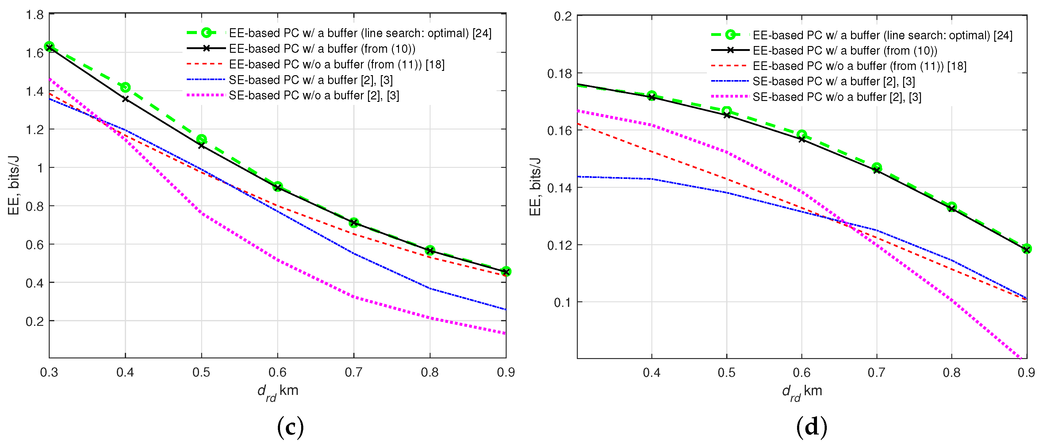
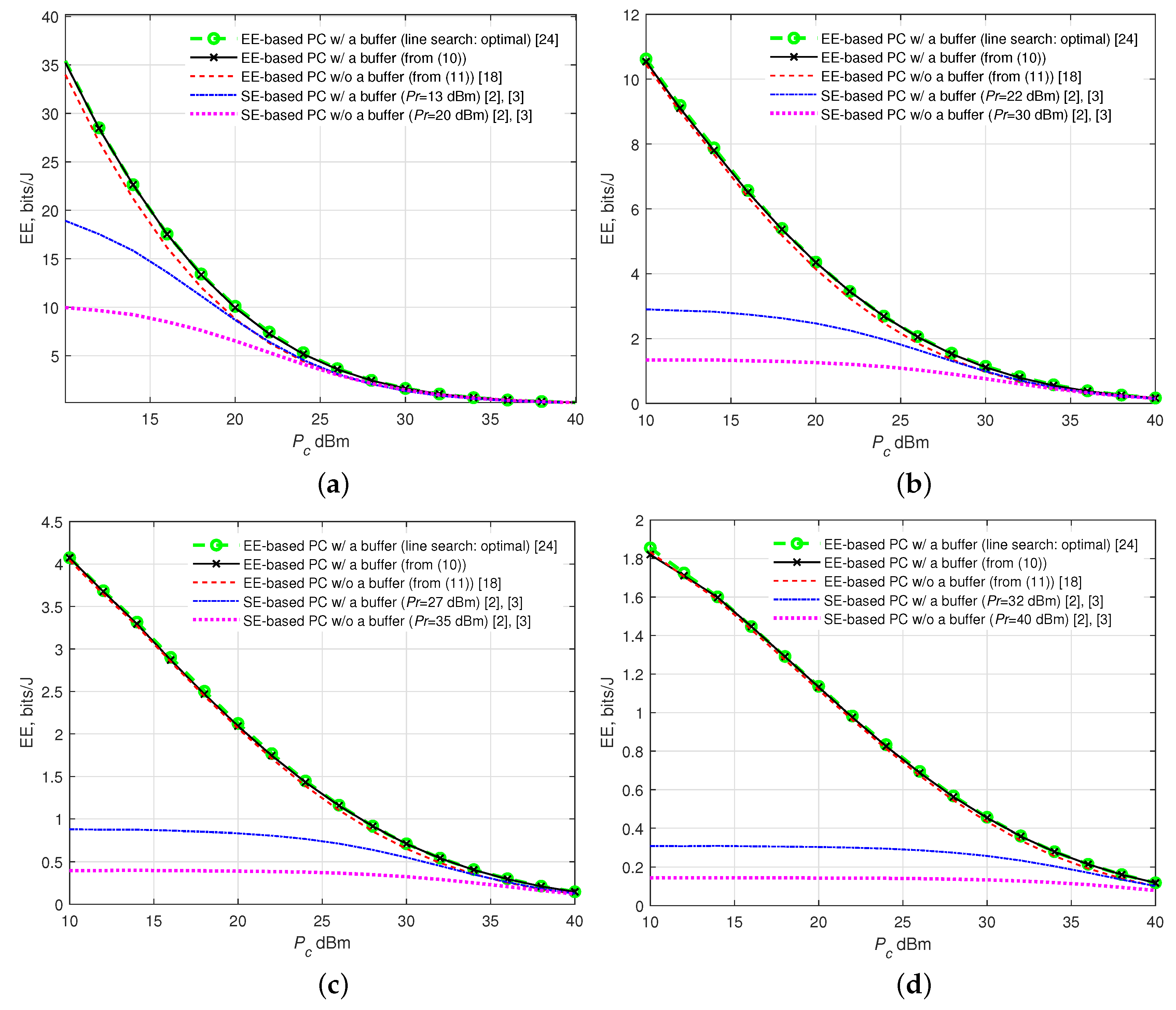
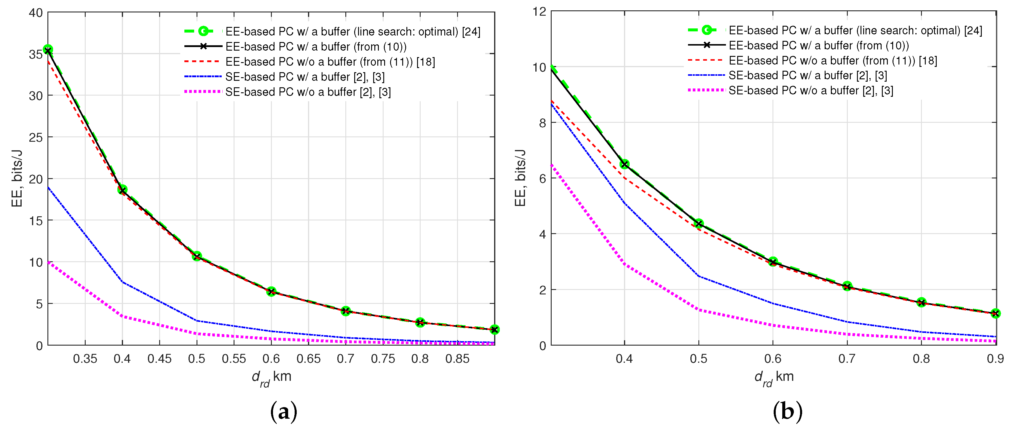
- EE-based PC w/ a buffer: The proposed RN system with a buffer. The RN transmit power is controlled by a one-dimensional numerical search. This method can be interpreted as a numerical approach of the optimal strategy in the work by the authors of [24], for a single pair of RN and DN. This is optimal yet impractical approach as stated in the previous section.
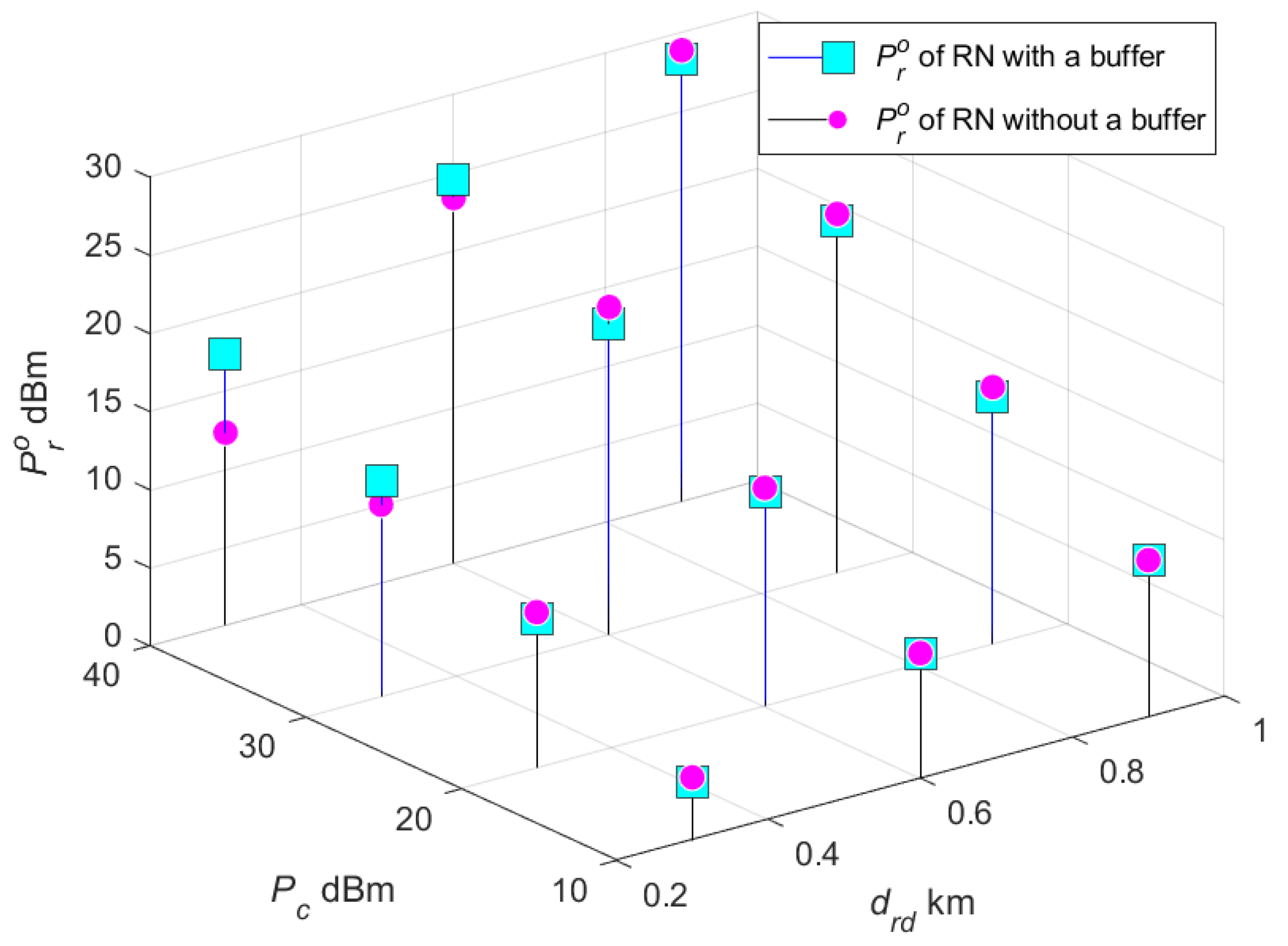
- EE-based PC w/ a buffer: The proposed RN system with a buffer. The RN transmit power is controlled by Equation (10).
- EE-based PC w/o a buffer: The conventional RN system without a buffer. The RN transmit power is controlled by Equation (11). The PC method is designed in this study, yet it is employed to the conventional RN for the sake of comparison. This method can be interpreted as an EE-based power control method in [18].
7. Conclusions
Author Contributions
Funding
Conflicts of Interest
References
- Cover, T.M.; El Gammal, A. Capacity theorems for relay channels. IEEE Trans. Inf. Theory 1979, 25, 572–584. [Google Scholar] [CrossRef]
- Rankov, B.; Wittneben, A. Spectral efficient protocols for half-duplex fading relay channels. IEEE J. Sel. Areas Commun. 2007, 25, 379–389. [Google Scholar] [CrossRef]
- Zhao, J.; Kuhn, M.; Wittneben, A.; Bauch, G. Cooperative transmission schemes for decode-and-forward relaying. In Proceedings of the 2007 IEEE 18th International Symposium on Personal, Indoor and Mobile Radio Communications, Athens, Greece, 3–7 September 2007; pp. 1–5. [Google Scholar]
- Darsena, D.; Gelli, G.; Iudice, I.; Verde, F. Widely-linear transceiver design for amplify-and-forward MIMO relaying. In Proceedings of the 2016 IEEE Sensor Array and Multichannel Signal Processing Workshop (SAM), Rio de Janeiro, Brazil, 10–13 July 2016; pp. 1–5. [Google Scholar]
- Barman Roy, S.; Madhukumar, A.S.; Joung, J. On joint Pareto frontier in multiple access and relay rate regions with Rayleigh fading. IEEE Trans. Veh. Technol. 2017, 66, 3777–3786. [Google Scholar]
- Joung, J.; Sayed, A.H. Multiuser two-way amplify-and-forward relay processing and power control methods for beamforming systems. IEEE Trans. Signal Process. 2010, 58, 1833–1846. [Google Scholar] [CrossRef]
- Joung, J.; Sayed, A.H. User selection methods for multiuser two-way relay communications using space division multiple access. IEEE Trans. Wirel. Commun. 2010, 9, 2130–2136. [Google Scholar] [CrossRef]
- Patel, C.S.; Stuber, G.L. Channel estimation for amplify and forward relay based cooperation diversity systems. IEEE Trans. Wirel. Commun. 2007, 6, 2348–2356. [Google Scholar] [CrossRef]
- Unger, T.; Klein, A. Applying relay stations with multiple antennas in the one- and two-way relay channel. In Proceedings of the IEEE 18th International Symposium on Personal, Indoor and Mobile Radio Communications, (PIMRC), Athens, Greece, 3–7 September 2007. [Google Scholar]
- Chun, B.; Jeong, E.R.; Joung, J.; Oh, Y.; Lee, Y.H. Pre-nulling for self-interference suppression in full-duplex relays. In Proceedings of the 2009 APSIPA Annual Summit and Conference, Sapporo, Japan, 4–7 October 2009; pp. 949–952. [Google Scholar]
- Joung, J.; Sun, S. Design and performance evaluation of multiple AF-relay processing in multi-cell environment. In Proceedings of the 2011 IEEE 73rd Vehicular Technology Conference (VTC Spring), Budapest, Hungary, 15–18 May 2011; pp. 1–5. [Google Scholar]
- Joung, J.; Sun, S. A simple network-power-saving resource allocation method for OFDMA cellular networks with multiple relays. In Proceedings of the 2011 IEEE International Conference on Acoustics, Speech and Signal Processing (ICASSP), Prague, Czech Republic, 22–27 May 2011; pp. 2504–2507. [Google Scholar]
- Hammerström, I.; Kuhn, M.; Eşli, C.; Zhao, J.; Wittneben, A.; Bauch, G. MIMO two-way relaying with transmit CSI at the relay. In Proceedings of the IEEE Signal Processing Advances in Wireless Communications (SPAWC), Helsinki, Finland, 17–20 June 2007. [Google Scholar]
- Ye, H.T.; Kang, X.; Liang, Y.C.; Joung, J. Full-duplex wireless-powered IoT networks with unmanned aerial vehicle. In Proceedings of the The 9th International Conf. ICT Convergence (ICTC), Jeju Island, Korea, 17–19 October 2018; pp. 1–4. [Google Scholar]
- Zhang, S.; Zhang, H.; He, Q.; Bian, K.; Song, L. Joint trajectory and power optimization for UAV relay networks. IEEE Commun. Lett. 2018, 22, 161–164. [Google Scholar] [CrossRef]
- Ye, H.T.; Kang, X.; Liang, Y.C.; Joung, J. Optimal time allocation for full-duplex wireless-powered IoT networks with unmanned aerial vehicle. In Proceedings of the IEEE International Conference on Communications (ICC), Shanghai, China, 20–24 May 2019; pp. 1–6. [Google Scholar]
- Kang, H.; Joung, J.; Ahn, J.; Kang, J. Secrecy-aware altitude optimization for quasistatic UAV base station without eavesdropper location information. IEEE Commun. Lett. 2019, 23, 851–854. [Google Scholar] [CrossRef]
- Joung, J.; Sun, S. Power efficient resource allocation for downlink OFDMA relay cellular networks. IEEE Trans. Signal Process. 2012, 60, 2447–2459. [Google Scholar] [CrossRef]
- Singh, K.; Ku, M.L.; Biswas, S.; Ratnarajah, T. Energy-efficient subcarrier pairing and power allocation for DF relay networks with an eavesdropper. Energies 2017, 10, 1953. [Google Scholar] [CrossRef]
- Zhang, J.; Zeng, Y.; Zhang, R. Spectrum and energy efficiency maximization in UAV-enabled mobile relaying. In Proceedings of the IEEE International Conference on Communications (ICC), Paris, France, 21–25 May 2017; pp. 1–6. [Google Scholar]
- Xia, B.; Fan, Y.; Thompson, J.; Poor, H.V. Buffering in a three-node relay network. IEEE Trans. Wirel. Commun. 2008, 7, 4492–4496. [Google Scholar] [CrossRef]
- Zlatanov, N.; Schober, R. Buffer-aided relaying with adaptive link selection-fixed and mixed rate transmission. IEEE Trans. Inf. Theory 2013, 59, 2816–28404. [Google Scholar] [CrossRef]
- Qiao, D. Effective capacity of buffer-aided full-duplex relay systems with selection relaying. IEEE Trans. Veh. Technol. 2016, 64, 117–129. [Google Scholar] [CrossRef]
- Hajipour, J.; Niya, J.M.; Ng, D.W.K. Energy-efficient resource allocation in buffer-aided wireless relay networks. IEEE Trans. Wirel. Commun. 2017, 16, 6648–6659. [Google Scholar] [CrossRef]
- Nakai, R.; Oiwa, M.; Sugiura, S. Generalized buffer-state-based relay selection for fixed-rate buffer-aided cooperative systems. In Proceedings of the IEEE 85th Vehicular Technology Conference (VTC Spring), Sydney, NSW, Australia, 4–7 June 2017; pp. 1–5. [Google Scholar]
- Haneda, K.; Kahra, E.; Wyne, S.; Icheln, C.; Vainikainen, P. Measurement of loop-back interference channels for outdoor-to-indoor full-duplex radio relays. In Proceedings of the Fourth European Conference Antennas and Propagation, Barcelona, Spain, 12–16 April 2010; pp. 1–5. [Google Scholar]
- Cumanan, K.; Ding, Z.; Rahulamathavan, Y.; Molu, M.M.; Chen, H. Robust MMSE beamforming for multiantenna relay networks. IEEE Trans. Veh. Technol. 2017, 66, 3900–3912. [Google Scholar] [CrossRef]
- Joung, J.; Sun, S. Phase rotation and link selection methods for DSTTD-based two-path relay systems. IEEE Commun. Lett. 2011, 15, 278–280. [Google Scholar] [CrossRef]
- Joung, J. Beamforming vector design for regenerative wired two-way relay systems. IET Electron. Lett. 2017, 53, 596–598. [Google Scholar] [CrossRef]
- Joung, J.; Choi, J. Linear precoder design for an AF two-way MIMO relay node with no source node precoding. IEEE Trans. Veh. Technol. 2017, 66, 10526–10531. [Google Scholar] [CrossRef]
- LTE; E-UTRA. RF Requirements for LTE Pico Node B; ETSI std., 136 931 V9.0.0; 2011. Available online: https://www.etsi.org/deliver/etsi_tr/136900_136999/136931/09.00.00_60/tr_136931v090000p.pdf (accessed on 22 August 2019).
- Joung, J.; Sun, S. Energy efficient power control for distributed transmitters with ZF-based multiuser MIMO precoding. IEEE Commun. Lett. 2013, 17, 1766–1769. [Google Scholar] [CrossRef]
- Joung, J.; Chia, Y.K.; Sun, S. Energy-efficient, large-scale distributed-antenna system (L-DAS) for multiple users. IEEE J. Sel. Topics Signal Process. 2014, 8, 954–965. [Google Scholar] [CrossRef]
- Joung, J.; Ho, C.K.; Sun, S. Spectral efficiency and energy efficiency of OFDM systems: Impact of power amplifiers and countermeasures. IEEE J. Sel. Areas Commun. 2014, 32, 208–220. [Google Scholar] [CrossRef]
- Rappaport, T.S. Wireless Communications, 2nd ed.; Prentice Hall: Upper Saddle River, NJ, USA, 2002. [Google Scholar]
- Joung, J.; Ho, C.K.; Sun, S. Power amplifier switching (PAS) for energy efficient systems. IEEE Wirel. Commun. Lett. 2013, 2, 14–17. [Google Scholar] [CrossRef]
- Joung, J.; Sun, S. EMA: Energy-efficiency-aware multiple access. IEEE Commun. Lett. 2014, 18, 1071–1074. [Google Scholar] [CrossRef]
- Joung, J.; Ho, C.K.; Adachi, K.; Sun, S. A survey on power-amplifier-centric techniques for spectrum and energy efficient wireless communications. IEEE Commun. Surv. Tutor. 2014, 17, 315–333. [Google Scholar] [CrossRef]
- Zeng, Y.; Xu, J.; Zhang, R. Energy minimization for wireless communication with rotary-wing UAV. IEEE Trans. Wirel. Commun. 2019, 18, 2329–2345. [Google Scholar] [CrossRef]
- Antoniou, A.; Lu, W.S. Practical Optimization: Algorithms and Engineering Applications, 1st ed.; Springer: New York, NY, USA, 2007. [Google Scholar]
- Joung, J. Machine learning-based antenna selection in wireless communications. IEEE Commun. Lett. 2016, 20, 2241–2244. [Google Scholar] [CrossRef]
- Jadoon, M.A.; Kim, S. Relay selection algorithm for wireless cooperative networks: A learning-based approach. IET Commun. 2017, 11, 1061–1066. [Google Scholar] [CrossRef]
- Abdelreheem, A.; Omer, O.A.; Esmaiel, H.; Mohamed, U.S. Deep learning-based relay selection in D2D millimeter wave communications. In Proceedings of the 2019 International Conference on Computer and Information Sciences (ICCIS), Milan, Italy, 30 October–1 November 2019; pp. 1–5. [Google Scholar]
- Chapra, S.C. Applied Numerical Methods with MATLAB for Engineerrs and Scientists, 3rd ed.; Mc Graw Hill: Singapore, 2012. [Google Scholar]


© 2019 by the authors. Licensee MDPI, Basel, Switzerland. This article is an open access article distributed under the terms and conditions of the Creative Commons Attribution (CC BY) license (http://creativecommons.org/licenses/by/4.0/).
Share and Cite
Joung, J.; Lee, H.L.; Zhao, J.; Kang, X. Power Control Method for Energy Efficient Buffer-Aided Relay Systems. Energies 2019, 12, 3234. https://doi.org/10.3390/en12173234
Joung J, Lee HL, Zhao J, Kang X. Power Control Method for Energy Efficient Buffer-Aided Relay Systems. Energies. 2019; 12(17):3234. https://doi.org/10.3390/en12173234
Chicago/Turabian StyleJoung, Jingon, Han Lim Lee, Jian Zhao, and Xin Kang. 2019. "Power Control Method for Energy Efficient Buffer-Aided Relay Systems" Energies 12, no. 17: 3234. https://doi.org/10.3390/en12173234
APA StyleJoung, J., Lee, H. L., Zhao, J., & Kang, X. (2019). Power Control Method for Energy Efficient Buffer-Aided Relay Systems. Energies, 12(17), 3234. https://doi.org/10.3390/en12173234