Abstract
This paper focuses on the finite physical dimensions thermodynamics (FPDT)-based design of combined endoreversible power and refrigeration cycles (CCHP). Four operating schemes were analyzed, one for the summer season and three for the winter season. These basic CCHP cycles should define the reference ones, having the maximum possible energy and exergy efficiencies considering real restrictive conditions. The FPDT design is an entropic approach because it defines and uses the dependences between the reference entropy and the control operational parameters characterizing the external energy interactions of CCHP subsystems. The FPDT introduces a generalization of CCHP systems design, due to the particular influences of entropy variations of the working fluids substituted with influences of four operational finite dimensions control parameters, i.e., two mean log temperature differences between the working fluids and external heat sources and two dimensionless thermal conductance inventories. Two useful energy interactions, power and cooling rate, were used as operational restrictive conditions. It was assumed that there are consumers required for the supplied heating rates depending on the energy operating scheme. The FPDT modeling evaluates main thermodynamic and heat transfer performances. The FPDT model presented in this paper is a general one, applicable to all endoreversible trigeneration cycles.
1. Introduction
The thermodynamic design and optimization of simple or complex thermal systems might be performed through the below methods.
- Equilibrium thermodynamics (ET) involves the reversible Carnot cycle and Carnot energy efficiency. Besides, they developed the methods of optimization of real cycles by using mean thermodynamic temperature, exergy, and irreversible entropy generation concepts. These additional concepts can evaluate the irreversibility of real cycles by comparison with the Carnot one. The use of the Carnot cycle does not take into account the time, respectively it has maximum–maximorum energy efficiency but zero power because it asks infinitesimal temperature differences, i.e., infinite time to fulfill the heat transfers between the working fluid and external heat reservoirs.
- Finite time thermodynamics (FTT) based on Curzon–Ahlborn–Novikov maximum power and energy efficiency at maximum power criteria. FTT considers the externally irreversible Carnot cycle that requires finite time to complete the heat transfers between the working fluid and external heat reservoirs. The main drawback of approaches based on FTT is the fact that it cannot be applied entirely for non-Carnot irreversible cycles, see for instance [1], where they concluded: “Things are not so straightforward that a simple formula may account for a variety of situations”.
- Finite physical dimensions thermodynamics (FTPD) allows various approaches based on energy/entropy, like in ET or on energy/entropy rates close to FTT. FTPD assessments are entropic approaches because they define and use the dependences between the reference entropy and the control operational parameters characterizing the external energy interactions of thermal systems. The particular influences of reference entropy variations of the working fluids are substituted with influences of operational finite dimensions control parameters, i.e., finite temperature differences, finite thermal conductance inventory of heat exchangers, and finite energy rates. The internal irreversibility of cycles can be quantified through extra irreversible entropy generation models depending on the working fluid nature and the type/geometry of thermal system. The FPDT restrictive design prerequisites of basic energy systems might consider constant reference entropy, constant heat input, constant power, or constant energy efficiency.
- Finite speed thermodynamics (FST) studies the interactions between moving solids and fluids. FST has a narrow domain of application, i.e., reciprocating thermal machines.
Cogeneration (CHP) and trigeneration (CCHP) are energy technologies that simultaneously supply two useful energy rates (heat and power) or three useful energy rates (refrigeration, heat, and power) based on a single thermal energy source. The usual design of these systems follows specific restrictive operational strategies, for instance constant or variable power, and constant or variable heat rate, and constant or variable refrigeration rate. The characteristics of energy sources and energy end-users impose specific restrictive operational strategies. The simplest thermodynamic design considers a single useful energy as a restrictive parameter (power, heat rate, or refrigeration rate). The complex thermodynamic design aims to correlate two or three useful energies as restrictive parameters (power and heat rate, or power, heat, and refrigeration rates). The optimization of CHP and CCHP systems assumes different energy scenarios connecting the input energy rates to the output energy rates. The thermodynamic design performs this optimization by means of auxiliary energy technologies, e.g., energy storage systems, and/or new heat exchangers. The optimized design of CHP and CCHP plants takes into account both thermodynamic efficiency (first and second law efficiencies) and economic and environmental ones (investment cost/depreciation, CO2 emissions, and life cycle and SWOT analyses). At the European level, new CHP systems must have energy efficiencies larger than 85%. CCHP systems do not have imposed minimum thermodynamic energy efficiencies, because refrigeration is usually performed in distributed grids operating on existing energy sources. The studies on CCHP systems either survey the design of new local applications or optimize existing system models. Recent theoretical and experimental research on CHP and CCHP energy technologies are focused on the analysis of different performance criteria and hierarchical control, on thermodynamic, exergo-economic, and thermo-economic optimization, and sensitivity analysis on reviews and comparison. Almost all publications evaluate, to different extents, the environmental or ecological aspects. Separately, many specific researches regarding new energy systems have been developed. For instance, the most suitable control strategy for certain cogeneration system by referring to the related standards available [2]; comparative analysis of different performance indices, applied to a real small-scale district heating network in operation [3]; exergy destruction rate in each component of Brayton cogeneration systems [4]; analysis based on marginal cost assessment of the internal flows and final products of the system, allowing to explain the optimal operation of the system and the role of the thermal energy storage (TES) in achieving the optimal solution [5]; primary energy savings analysis and exergy destruction analysis to compare decentralized power production through cogeneration/trigeneration systems and centralized thermal plants [6]; investigation of CCHP systems to exhibit the influence of various operating parameters on performance, CO2 emissions reduction, and exergy destruction in three modes of operation followed by optimization [7]; analysis of specific CCHP hybrid systems composed of a gas turbine, an organic Rankine cycle (ORC) cycle and an absorption refrigeration cycle, for residential usage [8]; ecological coefficient of performance, exergetic performance coefficient, and maximum available work of an irreversible Carnot power cycle [9]; an innovative trigeneration system which uses low temperature level heat sources [10]; development of an exergoeconomic optimization model to integrate solar energy into trigeneration systems producing electricity, heating, and cooling according to exergetic, economic, and environmental targets [11]; exergoeconomic optimization of a trigeneration system using total revenue requirement (TRR) and the cost of the total system product as objective function in optimization using a genetic algorithm technique [12]; a new objective function, representing total cost rate of the system product, including cost rate of each equipment and cost rate of environmental impact (NOx and CO), and minimizing the objective function using evolutionary genetic algorithm [13], an extensive overview of various energy—and exergy-based efficiencies used in the analysis of power cycles [14]; production and use of alternative fuels [15]; integrated heating and cooling with long-term heat storage [16]; residual energy recovery by using small engines such as Stirling [17]; optimization of heating systems based on geothermal heat pumps [18]; implementation of combined cycle power plant (CCPP for energy supply of future building stock [19]; and measures to adapt institutional and financial barriers that restrict the use of cogeneration and district heating networks in the EU-28 [20]; analysis of a small-scale CCHP with ORC engine powered by the combustion of olive pomace, experimental data and Aspen Plus simulation, CCHP system sizing and assessment [21]; proposal of a novel methodology, Trigeneration System Cascade Analysis (TriGenSCA), for developing an insight-based numerical Pinch Analysis technique to simultaneously target the minimum cooling, heating and power requirements for a total site energy system [22]; investigation of the potential energy, carbon emissions, and financial impact of the size of co/tri-generation systems on a real case scenario of an existing UK hotel, using Thermal Analysis Simulation software (TAS) and a payback methodology [23]; evaluation of the energetic feasibility and the performances of a novel residential micro-CCHP system, based on low temperature proton exchange membrane fuel cell power unit and half effect lithium bromide absorption chiller [24]; optimization and evaluation of a solar-driven trigeneration system with an organic Rankine cycle and an absorption heat pump operating with LiBr-H2O and which operates with nanofluid-based parabolic trough collectors [25]; proposal of a model where the non-linear part load characteristics of the gas turbine are linearized by means of physical insight of the working principles of turbomachinery [26]; analysis of the influence of erroneous estimation of the uncertain energy loads and prices on the optimal plant design and operation, exploring all the most frequent errors occurring in the estimation of energy loads and prices [27]; design of a system providing electricity by coupling photovoltaic/thermal collectors and a wind turbine [28]; investigation of the energy and environmental potential of a renewable trigeneration system in a residential application under Incheon (Korea) and Ottawa (Canada) weather conditions [29]; analysis of a hybrid solar-assisted trigeneration system composed of a 20 m2 solar field of evacuated tube collectors, a natural gas fired micro combined heat and power system delivering 12.5 kW of thermal power, an absorption heat pump (AHP) with a nominal cooling power of 17.6 kW, two storage tanks (hot and cold) and an electric auxiliary heater (AH) [30]; reports on a study of the modelling, validation and analysis of an integrated 1 MW (electrical output) tri-generation system energized by solar energy and evaluation of the impact of local climatic conditions in the Mediterranean region on the system performance [31]; methodology for multi-objective optimization of trigeneration plants, primarily applicable to the systems for buildings’ energy supply characterized by high load variations on daily, weekly and annual bases, as well as the components applicable for flexible operation [32]; utilization of waste heat from a gas turbine power plant is analyzed for simultaneous production of electricity by combining steam rankine cycle using heat recovery steam generator, of clean water by air gap membrane distillation plant and of cooling by single stage vapor absorption chiller [33]. Recently, proposed methods of thermal systems early design [34,35,36] apply finite physical dimensions thermodynamics (FPDT) to design, optimize, or perform sensitivity analysis of various thermal systems. Currently, studies are focused on developing complex systems, fueled or solar hybrid, and combined power cycles. Beside all of these researches, the optimized planning of CCHP systems asks for more complex models—see [37], where a mixed integer linear program (MILP) solver model was developed in order to minimize the operating costs of a CCHP system comprising multiple cogeneration engines, heat pumps and refrigeration cycles, and auxiliary heating peak boilers and heat storage devices.
This paper develops a general FPDT based design for all types of combined endoreversible power and refrigeration cycles. The paper’s logical structure includes the FPDT-based design statements, the basic mathematical model, the numerical results, one possible scenario in designing endoreversible trigeneration systems, discussion, and conclusion. This new FPDT model generalizes the design of CCHP systems, substituting the entropy variations of the working fluids by four operational finite dimensions control parameters. This method is applicable to various subsystem components, i.e., engine and refrigeration machine. Four operational schemes were analyzed, one for the summer season (case “a”), and three for the winter season (cases “b”, “c” and “d”). These endoreversible trigeneration systems might be used as reference CCHP in designing irreversible ones. These operational schemes can be combined in developing the reference trigeneration grids. The mathematical models can be applied to irreversible cycles through irreversibility-defined coefficients that should link the thermal cyclic interactions, e.g., entropy balance equation, i.e., through an overall number of internal irreversibility.
The FPDT modeling requires, as an input parameter, the ratio (x) of refrigeration rate to engine power. This ratio has a decisive influence upon the useful energy rates and first and second law efficiencies of the whole trigeneration system. This paper considers, as a possible scenario, a conventional ratio of x = 0.1. The increased values of x reduce the useful power and increase the heat transfer rates of the refrigeration cycle. The ratio of heating rate to engine power (y), especially during the winter season, depends on the energy operating scheme. The entire use of the heating rates requests specified customers of heating and of domestic hot water (DHW). Below, a possible scheme is presented (Figure 1) that can deliver constant heating rate for a variable number of customers, and constant heat rate for a constant number of DHW customers.
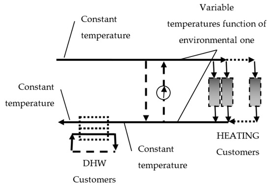
Figure 1.
The heating carrier flow, assuring constant heat rates for heating and domestic hot water (DHW).
The heating system adjusts the heat carrier inlet and outlet temperatures, depending on the environmental one. These variable temperatures can be attained with two by-pass flows between the inlet and the outlet, which maintain a constant heating rate for a variable number of customers and allow the control of inlet and outlet temperatures.
2. FPDT-Based Design Statements
Cogeneration and trigeneration are based on four main power cycles: Closed Rankine cycle, open Joule-Brayton cycle, open reciprocating engine cycles, and fuel cells. Four possible energy operating schemes of various generic trigeneration systems were analyzed (Figure 2):
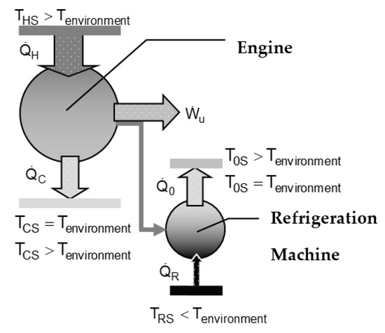
Figure 2.
Thermodynamic scheme of the trigeneration system.
- Supplying power and refrigeration rate, the summer season;
- Supplying power and heat rate by engine cycle, and refrigeration rate by reverse cycle, the winter season;
- Supplying power by engine cycle, and heat and refrigeration rates by reverse cycle, the winter season; and
- Supplying power and heat rate by engine cycle, and heat and refrigeration rates by reverse cycle, the winter season.
- TCS = Tenvironment, T0S = Tenvironment;
- TCS > Tenvironment, T0S = Tenvironment;
- TCS = Tenvironment, T0S > Tenvironment;
- TCS > Tenvironment, T0S > Tenvironment.
The FPDT-based design model set up firstly the reference entropy, i.e., the working fluid entropy rate during the reversible cyclic heat input of the trigeneration engine and refrigeration cycles. This design model adopted four finite dimensions control parameters:
- Two mean log temperature differences between the working fluids and external heat sources (ΔTH–the mean log temperature difference of the heat exchanger thermally linking the engine working fluid with the engine hot heat source; and ΔTR–the mean log temperature difference of the heat exchanger thermally linking the refrigeration working fluid with the refrigeration machine cold heat source); and
- Two dimensionless thermal conductance inventory:for the engine cycle, andfor the refrigeration cycle.
Two extra restrictive parameters (energy efficiency of engine and coefficient of performance—(COP) of refrigeration machine) were assumed in order to simplify the FPDT-based design.
The FPDT model of the endoreversible cycle generalizes and simplifies the preliminary design by assuming that operational finite physical dimensions main thermodynamic control parameters are not dependent on the nature of working fluids. The generalization is performed by using the specific first and second laws of thermodynamics’ relationships between the defined reference entropy/entropy rate and the finite physical dimensions main thermodynamic control parameters.
3. Basic Mathematical Model
The mathematical model combines equations of the first and second laws of thermodynamics with the linear heat transfer law, describing the heat transfers between working fluids and external heat reservoirs. These connections asked the definition of a new form of mean temperatures of external heat reservoirs in order to avoid any computational error. This new mean temperature is not a mean thermodynamic one, nor a mean log one, nor a mean integral one. It is the mean temperature fulfilling entirely the united equations. The FPDT mathematical models for engine and refrigeration cycles, and of the trigeneration system, are detailed below.
3.1. Engine
The reference entropy rate of the working fluid for the endoreversible engine cycle is :
The operational finite physical dimension control parameters are:
- -
- External heat reservoirs temperature ratio , and
- -
- Variable mean log temperature difference ΔTH [K], inside the heat exchanger working at the hot side of engine.
The main equations connecting the reference entropy rate of the working fluid to the operational finite physical dimension control parameters are presented below.
- Thermal conductance inventory:where U [kW·m−2·K−1] is the overall heat transfer coefficient and A [m2] is the heat transfer area.
- Energy balance Equations:
- Energy efficiency Equation:
- Exergy efficiency equation, related to exergy contents of :
where
- -
- [kg·s−1] is the mass flow rate of the working fluid through engine;
- -
- [kW] is the engine cycle input heat rate;
- -
- [K] is the mean thermodynamic temperature of the working fluid at the hot side;
- -
- [K] is, by definition, the fitting mean temperature of the hot heat source, complying with Equation (4);
- -
- [kW] is the engine cycle exhaust heat rate;
- -
- TC [K] is the mean thermodynamic temperature of the working fluid at the cold side; and
- -
- [K] is, by definition, the fitting mean temperature of the cold heat sink, complying with Equation (6).
3.2. Refrigeration Machine
- -
- The reference entropy rate of working fluid for the endoreversible reverse cycle is :The finite physical dimension control parameters are:
- -
- External heat reservoirs temperatures ratio , and
- -
- Variable mean log temperature difference ΔTC [K], inside the heat exchanger at the cold heat source of refrigeration machine.
The main equations connecting the reference entropy rate of the working fluid and the operational finite physical dimensions control parameters are presented below.
- Thermal conductance inventory:where U [kW·m−2·K−1] is the overall heat transfer coefficient and A [m2] is the heat transfer area.
- Energy balance Equations:
- Energy efficiency Equation:
- Exergy efficiency Equation, related to exergy contents of :
where
- -
- [kg·s−1] is the mass flow rate of the working fluid through the refrigeration machine;
- -
- [kW] is the refrigeration heat rate;
- -
- [K] is the mean thermodynamic temperature of the working fluid at the cycle cold side;
- -
- [K] is, by definition, the fitting mean temperature of the cold heat source, complying with Equation (14);
- -
- [kW] is the absolute heat rate at the hot heat sink;
- -
- [K] is mean thermodynamic temperature of the working fluid at the cycle hot side; and
- -
- T0S is, by definition, the fitting mean temperature of the hot heat sink, complying with Equation (16).
3.3. Endoreversible Trigeneration System
The dependences between the reference entropies, and , and the adopted finite dimensions control parameters have to be defined as functions of operational restrictive conditions imposed by the consumers of useful energies. The possible operational restrictive conditions include the specific parameters of useful energies, i.e., power, refrigeration rate and temperatures, and heating rate and temperatures. The prime energy is useful engine power. The refrigeration and heating rates might be evaluated through two ratios, the ratio of refrigeration rate to power (x) and the ratio of heating rate to power (y). This paper considered, as a possible scenario, imposed engine power and imposed refrigeration rate and temperatures. The ratio of heating rate to engine power (y), especially during the winter season, is dependent on the energy operating scheme.
For a specified value for power, from Equation (8) yields and the new forms of Equations (4)–(6) are:
For a specified value of refrigeration rate , from Equation (14) yields and the new forms of Equations (15) and (16), and (18) are:
● Energy efficiency Equation of the trigeneration system:
The general equation of energy efficiency (EE) of the whole system is the ratio where for all cases .
The term has specific forms for each case a, b, c and d, that involve the below energy balance Equations:
The energy balance equations of the whole system:
The energy balance equations of the subsystems:
where is the energy efficiency in the case of cogeneration through engine cycle and is the useful heat rate supplied by engine cogeneration.
Thus, it yields a general restriction for all cases:
where is the minimum admissible useful power, required by the power end users.
- Case “a”—energy efficiency:
- Case “b”—energy efficiency:
- Case “c”—energy efficiency:
- Case “d”—energy efficiency:
Equations (34) and (36) considered the engine cogeneration energy efficiency of EEcog ≤ 1 . Also, zero heat losses were assumed along the delivering path of useful thermal energies (heating) for all cases.
For all cases, the useful power is:
● Exergy efficiency equation of the trigeneration system:
where
, , , are the exergy contents of thermal energy rates , , , ; ΔTC and ΔT0 comply with Equations (7) and (17); and Te is the environmental temperature.
Equations (7), (17) and (21)–(40) provide the complete preliminary mathematical algorithm to design the endoreversible trigeneration systems. Equations for energy efficiency could also be applied to irreversible systems, if real energy efficiencies of system components are known, i.e., EEcog, EEE,real, and COPreal, and ratios x and y. The restrictive operational conditions , TCS, TRS, x, y, θHS, and θRS are imposed by the end-users of useful energies. The variable finite dimensions control parameters are gH, gR, ΔTH, and ΔTR. The thermodynamic functions of the system components (engine and refrigeration machine), defined by Equations (1)–(20) depend on two parameters (gH and ΔTH for engine, gR and ΔTR for refrigeration machine). The energy and exergy efficiencies of the trigeneration systems are dependent on all four variable finite dimensions parameters. In this paper, efficiency evaluation was simplified by assuming two extra restrictive conditions: EEE = EEE0 and COP = COP0, both close to maximum value, and the additional simplifying constraint EEcog = 1.
4. Numerical Results
The possible value ranges of ΔTH and of ΔTR were determined based on two extra restrictive conditions, energy efficiency of engine and COP of refrigeration machine, respectively, close to the maximum possible values obtained by the FPDT numerical results of the endoreversible trigeneration subsystem.
The general design energy rates of the trigeneration system are kW and . The restrictive design conditions are included in Table 1. The dimensionless thermal conductance gH and gR were defined through Equations (9) and (19) by imposing engine energy efficiency and refrigeration COP. The numerical results are presented in Table 2 and Figure 3, Figure 4, Figure 5, Figure 6, Figure 7, Figure 8, Figure 9, Figure 10, Figure 11, Figure 12, Figure 13, Figure 14, Figure 15, Figure 16, Figure 17, Figure 18, Figure 19, Figure 20 and Figure 21.

Table 1.
The design restrictive conditions of the trigeneration system.
Table 2.
Constant numerical results for the operational parameters.
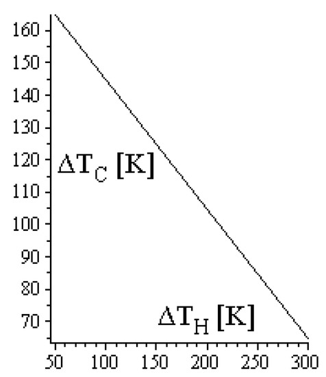
Figure 3.
ΔTC dependence of ΔTH—case “a”.
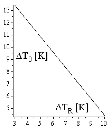
Figure 4.
ΔT0 dependence of ΔTR—case “a”.
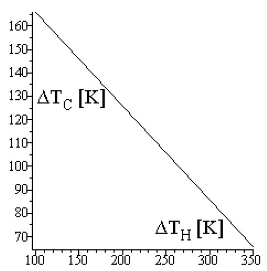
Figure 5.
ΔTC dependence of ΔTH—case “b”.
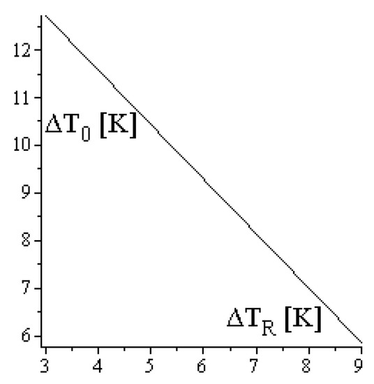
Figure 6.
ΔT0 dependence of ΔTR—case “b”.
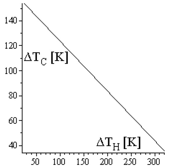
Figure 7.
ΔTC dependence of ΔTH—case “c”.
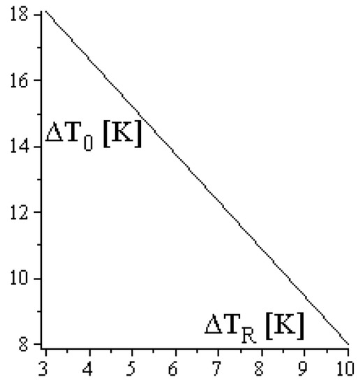
Figure 8.
ΔT0 dependence of ΔTR—case “c”.
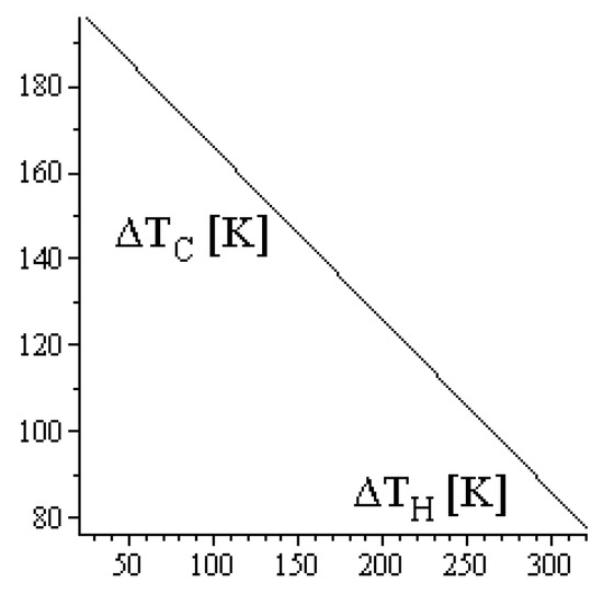
Figure 9.
ΔTC dependence of ΔTH—case “d”.
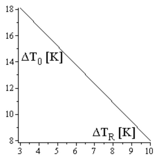
Figure 10.
ΔT0 dependence of ΔTR—case “d”.

Figure 11.
ExEb dependence of ΔTH.
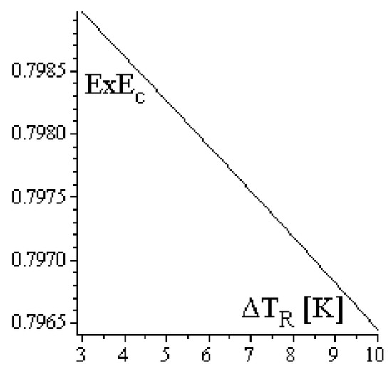
Figure 12.
ExEc dependence of ΔTR.
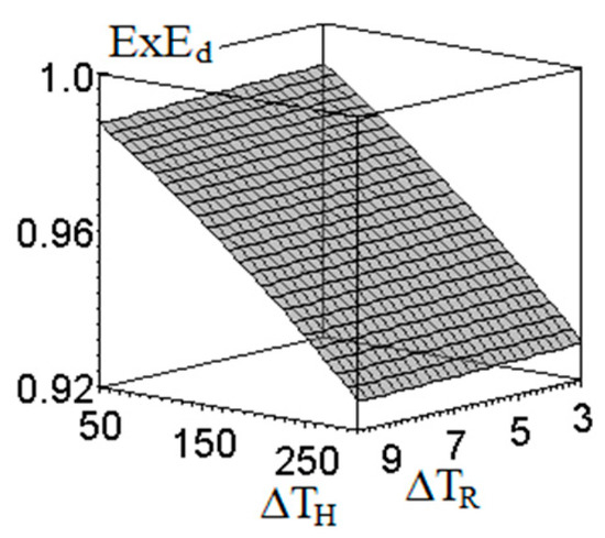
Figure 13.
ExEd dependence of ΔTH and ΔTR.
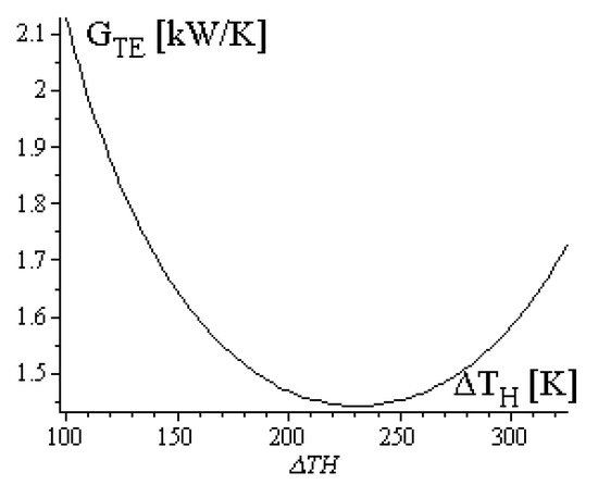
Figure 14.
GTE dependence of ΔTH—case “a”. GTEmin = 1.443 kW/K for ΔTH = 231 K.
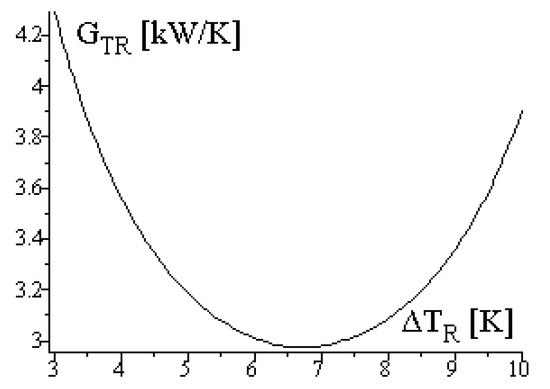
Figure 15.
GTR dependence of ΔTR—case “a”. GTRmin = 2.975 kW/K for ΔTR = 6.72 K.
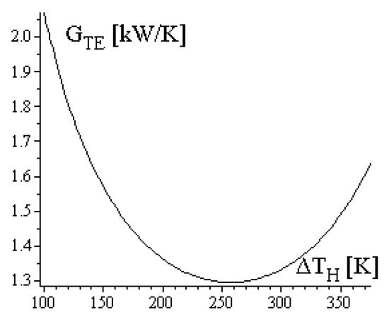
Figure 16.
GTE dependence of ΔTH—case “b”. GTEmin = 1.296 for ΔTH = 257 K.
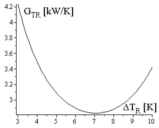
Figure 17.
GTR dependence of ΔTR—case “b”. GTRmin = 2.832 for ΔTR = 7.06 K.
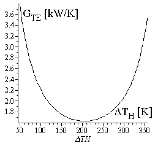
Figure 18.
GTE dependence of ΔTH—case “c”. GTEmin = 1.628 for ΔTH = 204.75 K.
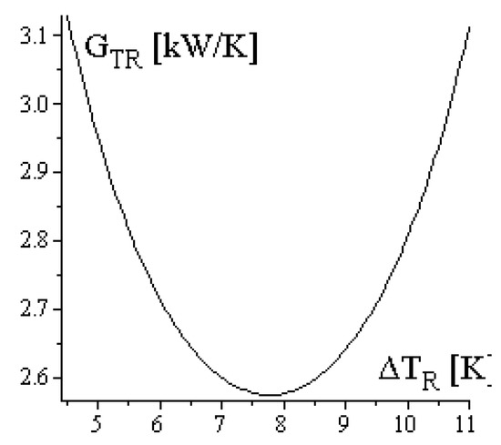
Figure 19.
GTR dependence of ΔTR—case “c”. GTRmin = 2.574 for ΔTR = 7.77 K.
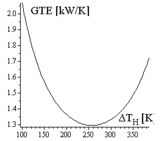
Figure 20.
GTE dependence of ΔTH—case “d”. GTEmin = 1.295 for ΔTH = 257 K.
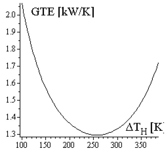
Figure 21.
GTR dependence of ΔTR—case “d”. GTRmin = 2.574 for ΔTR = 7.77 K.
The dependences ΔTH of ΔTH and ΔT0 of ΔTR, respectively, are similar for all cases, i.e., the larger the values of ΔTH and ΔTR, the smaller the values of ΔTC and ΔT0. Figure 7 and Figure 9 are identical because the refrigeration cycles works in identical operation restrictive conditions, i.e., identical T0S, TRS, gR.
While the exergy efficiency of case “a” is constant, the exergy efficiencies of cases “b”, “c” and “d” depend on the finite temperature differences ΔTH and ΔTR. The influence of ΔTH is physically more significant than that of ΔTR.
All Equations for thermal conductance inventory exhibit minimum values corresponding to gH = 0.5 and gR = 0.5. This quality is compatible with minimum investment costs (minimum CAPEX) regarding the heat exchangers of the trigeneration subsystems.
5. Design of Endoreversible Trigeneration Systems
The FPDT-based design of endoreversible trigeneration systems depends on the restrictive conditions of each specific application. Possible operational restrictive conditions might refer to the customers’ requirements regarding useful energies from the trigeneration system: Only useful power, only refrigeration rate, only heating rate, or simultaneously two or three useful energies. The design optimization might take into account extra restrictive conditions related to the operation of the trigeneration subsystems, such as: Imposed reference entropy rate of the working fluids, imposed input heat rate, imposed power, or imposed energy efficiency. The trigeneration system design is demonstrated here for the case of imposed useful power. The operational interrelated restrictive conditions are:
- Imposed useful minimum power, , that implies
- Imposed consumed power by refrigeration machine, ,
- Imposed ratio of engine power to refrigeration rate, ,
- Imposed refrigeration rate, , and
- Imposed cogeneration energy efficiency, ; thus it assumes that there are existing consumers of all the useful heat rates (DHW and heating customers).
The trigeneration subsystem design considered only the optimized dimensionless thermal conductance inventory, i.e., gH = 0.5 and gR = 0.5 corresponding to minimum CAPEX of heat exchangers. The numerical results are included in Table 3.
Table 3.
Numerical results of the trigeneration system design.
The design considered various temperature ratios of engine external heat reservoirs, θHS, and imposed temperatures of refrigeration machine external heat reservoirs, TRS, T0S. Therefore, all engine operational parameters were obtained through the FPDT model. The refrigeration machine operational parameters were determined by adopting a COP value of about 60% of COPCarnot.
6. Discussion
Development of proof thermodynamic design models for trigeneration systems has to be performed by several logical stages, synthetically presented below.
- Defining the reference complete reversible trigeneration models for all possible schemes of providing imposed useful energies. This stage was well performed by considering the Carnot cycle.
- Defining the reference endoreversible trigeneration models for all possible schemes of providing imposed useful energies. This stage might be well achieved through FPDT mathematical models. These models allow the generalization of design results, not depending on the working fluid nature.
- The limitations of endoreversibility have to be assessed for cases when the reversible model cannot be applied entirely for all possible cycles, see for instance [1]. The limitations of the Carnot cycle are exceeded through mean thermodynamic temperature concepts. Thus, the Carnot model remains as the reference for all types of irreversible cycles. The comparison, reversible–irreversible, is performed through lost exergy, irreversible entropy generation, and second law efficiency concepts. The Curzon–Ahlborn–Novikov approach has limitations related to the efficiency at maximum power because it does not imply the entropy/entropy balance in its mathematical model. In this paper, the basic endoreversible trigeneration mathematical models considering all endoreversible non-Carnot cycles were generalized through the mean thermodynamic concept and the new defined mean temperature of external heat reservoirs complying with coupled energy conservation and linear heat transfer equations. These mathematical models would be the reference ones to compare reversibility–irreversibility, either by lost exergy/second law efficiency or by an overall number of internal irreversibility, see [38].
- Defining the reference models assessing the irreversibility influence. The equilibrium thermodynamics were completed through the means of thermodynamic temperature, exergy, and irreversible entropy generation concepts. The FPDT assessments might be completed either defining a single concept evaluating priori the overall internal irreversibility, see for instance the short communication [38], or making a sensitivity analysis of each operational trigeneration scheme depending on the working fluid nature and on the type of thermal system.
- Defining the optimization methods of reference reversible and irreversible cycles. The optimization methods consider either pure thermodynamic criteria, CAPEX criteria, operational costs criteria (see for instance [24]), environmental criteria (see LCA method), or improvement of a specific defined efficiency of thermal systems. The more elaborated methods combine different criteria.
- Defining the reference models for possible interconnected trigeneration grids and the evaluation of performances, energy interactions, investments, operational costs, environmental effects, preservation of natural resources.
- Defining the optimization methods for possible interconnected trigeneration grids. One good method might use MILP models, see reference [37].
The present paper is developed inside stage two. Four possible operational schemes were defined, one for the summer season and three for the winter season. The developed mathematical model designs of endoreversible trigeneration systems might be used as reference CCHP in designing irreversible ones. The proposed models use FPDT principles to minimize the number of adjustable finite physical dimensions design parameters that accomplish the customer’s requirements of these energy systems. The next stages, three and four, will be accomplished by generalized assessments involving the overall number of internal irreversibility concept, see [25], and complying with FPDT principles.
7. Conclusions
This paper proposes an original FPDT approach design of endoreversible trigeneration cycles. Four operational schemes were analyzed, one for the summer season (case “a”), and three for the winter season (cases “b”, “c”, and “d”). These endoreversible trigeneration systems might be used as reference CCHP in designing irreversible ones.
The FPDT generalizes the design of CCHP systems by substituting the entropy variations of the working fluids with four operational finite dimensions control parameters. Therefore, the design could apply to various subsystem components, i.e., engine and refrigeration machine. When applied to endoreversible cycles of trigeneration systems, the preliminary design is simplified by defining a complete thermodynamic and optimized design, depending on particular imposed restrictive operational conditions.
They were defined as the basic possible trigeneration reference operational schemes and the generalized FPDT mathematical models for each scheme. The operational schemes can be combined in developing the reference trigeneration grids. The mathematical models can be applied to irreversible cycles through irreversibility-defined coefficients that should link the thermal cyclic interactions, e.g., entropy balance equation, i.e., through an overall number of internal irreversibility.
The FPDT design model of the trigeneration component endoreversible cycles emphasizes the cycle’s internal relationships between the operational functions and the restrictive imposed variable finite physical dimensions parameters. These relationships are similar for all cases. The presented FPDT design of the whole endoreversible trigeneration system revealed the minimization of thermal conductance inventory (GTE and GTR). This fact it is very important, because minimum thermal conductance inventory denotes minimum investment costs (CAPEX) for corresponding heat exchangers.
The Energy Efficiency functions depend on x, EEcog, EEE, and COP. These equations could also be applied to irreversible systems, if the real energy efficiencies of system components are known, i.e., x, EEcog,real, EEE,real, COPreal, and the lost heat along the flow paths of useful thermal energy fluids carrier. These values might be larger than unity (see Table 2 and Table 3). Unfortunately, it is difficult to propose a single value for typical trigeneration systems and therefore, the generalized schemes of basic trigeneration systems have to be developed to then determine the imposed minimum specific energy efficiency value.
Future FPDT work will develop the sensitivity analysis of irreversibility influence. This analysis has to specify the nature of cycles (e.g., engine: Rankine, Joule-Brayton, reciprocating ones; and refrigeration machine: Vapor or gas compression or absorption), and the nature of the working fluids, because the magnitude of irreversibility strongly depends on thermodynamic and thermal properties.
Author Contributions
Conceptualization, methodology, formal analysis, D.G. and F.M.; validation, writing—original draft preparation, funding acquisition, D.G.; writing—review and editing, D.G. and P.A.; supervision, original draft preparation, F.M; software validation, G.S.
Funding
This research was funded by UEFISCDI Romania—research grant PCCDI 32/2018.
Conflicts of Interest
The authors declare no conflict of interest.
References
- Ouerdane, H.; Apertet, Y.; Goupil, C.; Lecoeur, P. Continuity and boundary conditions in thermodynamics: From Carnot’s efficiency to efficiencies at maximum power. Eur. Phys. J. Spec. Top. 2015, 224, 862. [Google Scholar] [CrossRef]
- Isa, N.M.; Tan, C.W.; Yatim, A. A comprehensive review of cogeneration system in a microgrid: A perspective from architecture and operating system. Renew. Sustain. Energy Rev. 2018, 81, 2236–2263. [Google Scholar] [CrossRef]
- Badami, M.; Gerboni, R.; Portoraro, A. Determination and assessment of indices for the energy performance of district heating with cogeneration plants. Energy 2017, 127, 697–703. [Google Scholar] [CrossRef]
- Khaliq, A.; Dincer, I. Energetic and exergetic performance analyses of a combined heat and power plant with absorption inlet cooling and evaporative aftercooling. Energy 2011, 36, 2662–2670. [Google Scholar] [CrossRef]
- Pina, E.A.; Lozano, M.A.; Serra, L.M. Optimal operation and marginal costs in simple trigeneration systems including thermal energy storage. Energy 2017, 135, 788–798. [Google Scholar] [CrossRef]
- Santo, D.B.D.E.; Gallo, W.L.R. Utilizing primary energy savings and exergy destruction to compare centralized thermal plants and cogeneration/trigeneration systems. Energy 2017, 120, 785–795. [Google Scholar] [CrossRef]
- Memon, A.G.; Memon, R.A. Thermodynamic analysis of a trigeneration system proposed for residential application. Energy Convers. Manag. 2017, 145, 182–203. [Google Scholar] [CrossRef]
- Mohammadi, A.; Kasaeian, A.; Pourfayaz, F.; Ahmadi, M.H. Thermodynamic analysis of a combined gas turbine, ORC cycle and absorption refrigeration for a CCHP system. Appl. Therm. Eng. 2017, 111, 397–406. [Google Scholar] [CrossRef]
- Ahmadi, M.H.; Ahmadi, M.A.; Pourfayaz, F. Thermodynamic analysis and evolutionary algorithm based on multi-objective optimization performance of actual power generating thermal cycles. Appl. Therm. Eng. 2016, 99, 996–1005. [Google Scholar] [CrossRef]
- Bellos, E.; Tzivanidis, C.; Antonopoulos, K.A. Parametric investigation and optimization of an innovative trigeneration system. Energy Convers. Manag. 2016, 127, 515–525. [Google Scholar] [CrossRef]
- Baghernejad, A.; Yaghoubi, M.; Jafarpur, K. Exergoeconomic optimization and environmental analysis of a novel solar-trigeneration system for heating, cooling and power production purpose. Sol. Energy 2016, 134, 165–179. [Google Scholar] [CrossRef]
- Ghaebi, H.; Saidi, M.; Ahmadi, P. Exergoeconomic optimization of a trigeneration system for heating, cooling and power production purpose based on TRR method and using evolutionary algorithm. Appl. Therm. Eng. 2012, 36, 113–125. [Google Scholar] [CrossRef]
- Ahmadi, P.; Dincer, I. Exergoenvironmental analysis and optimization of a cogeneration plant system using Multimodal Genetic Algorithm (MGA). Energy 2010, 35, 5161–5172. [Google Scholar] [CrossRef]
- Kanoglu, M.; Dincer, I.; Rosen, M.A. Understanding energy and exergy efficiencies for improved energy management in power plants. Energy Policy 2007, 35, 3967–3978. [Google Scholar] [CrossRef]
- Mustafa, M.F.; Nord, N.; Calay, R.K.; Mustafa, M.Y. A Hybrid Biomass Hydrothermal Gasification- Solid Oxide Fuel Cell System Combined with Improved CHP Plant for Sustainable Power Generation. Energy Procedia 2017, 112, 467–472. [Google Scholar] [CrossRef]
- Rohde, D.; Andresen, T.; Nord, N. Analysis of an integrated heating and cooling system for a building complex with focus on long–term thermal storage. Appl. Therm. Eng. 2018, 145, 791–803. [Google Scholar] [CrossRef]
- Colmenar-Santos, A.; Zarzuelo-Puch, G.; Borge-Diez, D.; García-Diéguez, C. Thermodynamic and exergoeconomic analysis of energy recovery system of biogas from a wastewater treatment plant and use in a Stirling engine. Renew. Energy 2016, 88, 171–184. [Google Scholar] [CrossRef]
- Blazqueza, C.S.; Borge-Diezb, D.; Nietoa, I.M.; Martina, A.F.; Gonzalez-Aguileraa, D. Technical optimization of the energy supply in geothermal heat pumps. Geothermics 2019, 81, 133–142. [Google Scholar] [CrossRef]
- Tereshchenko, T.; Nord, N. Implementation of CCPP for energy supply of future building stock. Appl. Energy 2015, 155, 753–765. [Google Scholar] [CrossRef]
- Colmenar-Santos, A.; Rosales-Asensio, E.; Borge-Diez, D.; Mur-Perez, F. Cogeneration and district heating networks: Measures to remove institutional and financial barriers that restrict their joint use in the EU-28. Energy 2015, 85, 403–414. [Google Scholar] [CrossRef]
- Colantoni, A.; Villarini, M.; Marcantonio, V.; Gallucci, F.; Cecchini, M. Performance Analysis of a Small-Scale ORC Trigeneration System Powered by the Combustion of Olive Pomace. Energies 2019, 12, 2279. [Google Scholar] [CrossRef]
- Jamaluddin, K.; Alwi, S.R.W.; Manan, Z.A.; Hamzah, K.; Klemeš, J.J. A Process Integration Method for Total Site Cooling, Heating and Power Optimisation with Trigeneration Systems. Energies 2019, 12, 1030. [Google Scholar] [CrossRef]
- Salem, R.; Bahadori-Jahromi, A.; Mylona, A.; Godfrey, P.; Cook, D. Comparison and Evaluation of the Potential Energy, Carbon Emissions, and Financial Impacts from the Incorporation of CHP and CCHP Systems in Existing UK Hotel Buildings. Energies 2018, 11, 1219. [Google Scholar] [CrossRef]
- Cozzolino, R. Thermodynamic Performance Assessment of a Novel Micro-CCHP System Based on a Low Temperature PEMFC Power Unit and a Half-Effect Li/Br Absorption Chiller. Energies 2018, 11, 315. [Google Scholar] [CrossRef]
- Bellos, E.; Tzivanidis, C. Optimization of a Solar-Driven Trigeneration System with Nanofluid-Based Parabolic Trough Collectors. Energies 2017, 10, 848. [Google Scholar] [CrossRef]
- Gopisetty, S.; Treffinger, P. Generic Combined Heat and Power (CHP) Model for the Concept Phase of Energy Planning Process. Energies 2017, 10, 11. [Google Scholar] [CrossRef]
- Piacentino, A.; Gallea, R.; Catrini, P.; Cardona, F.; Panno, D. On the Reliability of Optimization Results for Trigeneration Systems in Buildings, in the Presence of Price Uncertainties and Erroneous Load Estimation. Energies 2016, 9, 1049. [Google Scholar] [CrossRef]
- Acevedo, L.; Uche, J.; Del Almo, A.; Círez, F.; Usón, S.; Martínez, A.; Guedea, I. Dynamic Simulation of a Trigeneration Scheme for Domestic Purposes Based on Hybrid Techniques. Energies 2016, 9, 1013. [Google Scholar] [CrossRef]
- Kang, E.-C.; Lee, E.-J.; Ghorab, M.; Yang, L.; Entchev, E.; Lee, K.-S.; Lyu, N.-J. Investigation of Energy and Environmental Potentials of a Renewable Trigeneration System in a Residential Application. Energies 2016, 9, 760. [Google Scholar] [CrossRef]
- Marrasso, E.; Roselli, C.; Sasso, M.; Tariello, F. Analysis of a Hybrid Solar-Assisted Trigeneration System. Energies 2016, 9, 705. [Google Scholar] [CrossRef]
- Mathkor, R.Z.; Agnew, B.; Al-Weshahi, M.A.; Latrsh, F. Exergetic Analysis of an Integrated Tri-Generation Organic Rankine Cycle. Energies 2015, 8, 8835–8856. [Google Scholar] [CrossRef]
- Stojiljković, M.M.; Stojiljković, M.M.; Blagojević, B.D. Multi-Objective Combinatorial Optimization of Trigeneration Plants Based on Metaheuristics. Energies 2014, 7, 8554–8581. [Google Scholar] [CrossRef]
- Mohan, G.; Dahal, S.; Kumar, U.; Martin, A.; Kayal, H. Development of Natural Gas Fired Combined Cycle Plant for Tri-Generation of Power, Cooling and Clean Water Using Waste Heat Recovery: Techno-Economic Analysis. Energies 2014, 7, 6358–6381. [Google Scholar] [CrossRef]
- Feidt, M. Finite Physical Dimensions Optimal Thermodynamics 1; Elsevier: Amsterdam, The Netherlands, 2017. [Google Scholar]
- Feidt, M. Finite Physical Dimensions Optimal Thermodynamics 2; Elsevier: Amsterdam, The Netherlands, 2018. [Google Scholar]
- Feidt, M.; Dumitraşcu, G.; Horbaniuc, B. Sensitivity Analysis of an Endoreversible CARNOT Energy Converter Using Finite Physical Dimensions Thermodynamics, Colloque Francophone en Energie, Environnement, Economie et Thermodynamique, June 28–29, 2018; INSA: Strasbourg, France, 2018. [Google Scholar]
- Bischi, A.; Taccari, L.; Martelli, E.; Amaldi, E.; Manzolini, G.; Silva, P.; Campanari, S.; Macchi, E. A detailed MILP optimization model for combined cooling, heat and power system operation planning. Energy 2014, 74, 12–26. [Google Scholar] [CrossRef]
- Dumitrașcu, G. The way to optimize the irreversible cycles. Rev. Termotehnica 2008, 2, 18–22. [Google Scholar]
© 2019 by the authors. Licensee MDPI, Basel, Switzerland. This article is an open access article distributed under the terms and conditions of the Creative Commons Attribution (CC BY) license (http://creativecommons.org/licenses/by/4.0/).