Article

Performance Analysis of Heat Pump Dryer with Unit-Room in Cold Climate Regions

1
Technical Institute of Physics and Chemistry, Chinese Academy of Sciences, Beijing 100190, China
2
University of Chinese Academy of Sciences, Beijing 100049, China
3
Sustainable Buildings Research Centre (SBRC), University of Wollongong (UOW), Wollongong, NSW 2519, Australia
4
Guangdong Institute of Modern Agricultural Equipment, Guangzhou 510640, China
*
Author to whom correspondence should be addressed.
Energies 2019, 12(16), 3125; https://doi.org/10.3390/en12163125
Submission received: 18 June 2019 / Revised: 30 July 2019 / Accepted: 7 August 2019 / Published: 14 August 2019

Abstract

:
This study presents the development and evaluation of a novel partially open-loop heat pump dryer with a unit-room (HPDU). The unit-room was designed to enable the ambient air to be mixed with the return air, thereby reducing the influence of the ambient air on the system performance, while maintaining a high system thermal efficiency. A modelling system for the HPDU was developed and validated based on a real-scale experimental study. By using the modelling system, the system characteristics under different ambient conditions and bypass factors were analyzed. The energy benefit of the proposed HPDU was quantified through a comparative study with a closed-loop heat pump dryer (CHPD). It is evident that a maximal specific moisture extraction rate (SMER) and a minimal total energy consumption (TEC) existed when changing the bypass factor of the HPDU under certain ambient temperatures. Compared to the CHPD, the coefficient of performance (COP) of the HPDU increased by up to 39.56%, presenting a significant energy benefit for the application of HPDU.

1. Introduction

Drying is one of the most energy-intensive industrial processes, which accounts for approximately 5%~25% energy consumption in various industries [1]. It consumes, for example, up to 70% of the total energy used in the timber industry [2], 50% of that in the textile manufacturing industry [2], and 60% of that in the Chinese noodles producing industry [3]. Besides the high energy consumption, another concern in the conventional drying process is low thermal efficiency, which is mainly due to the exhaustion of the moist air from drying chambers. In contrast, the utilization of the heat pump dryer (HPDs) can recycle both the latent heat and the sensible heat of the exhaust air, or extract heat from the ambient air to facilitate the drying process. The HPDs also have other significant advantages, such as the higher specific moisture extraction rate (SMER), better drying product quality, less drying time required, and so on [4].
With the widely held application of the HPDs in industry, various HPD technologies have been developed and promoted. The HPDs could be divided into three categories based on the air loops: The open-loop type [5,6,7]; the partially open-loop type [8,9,10]; the closed-loop type [11,12,13]. For the open-loop type heat pump dryers (OHPDs), the drying performance is directly affected by the ambient conditions [14], since the heat source is typically the ambient air. As the heat pumps in the OHPDs, they may have poor performance in cold climates [15,16], and some solutions have been proposed to address the problem so as to maintain a high heating capacity at the desired heating temperature when there is low ambient air temperature. For instance, Shen et al. [17] developed an OHPD that had dual operation modes including a single cycle and a cascade cycle, in which the cascade cycle operation of the heat pump was utilized if the single cycle operation did not provide a desired heating capacity. However, it failed to improve the energy efficiency of the HDP, and was associated with a high initial investment. Şevik and his research group [18,19] proposed and experimentally evaluated the performance of a solar assisted heat pump drying system, in which solar energy was used as an auxiliary heat source of the system when the heat pumps failed to meet the desired heating capacity. Colak and Hepbasli [20] presented a ground source heat pump based OHPD which was able to eliminate the impact of the ambient air using the geothermal source with relatively stable temperatures. Different from an OHPD, the performance of a closed-loop heat pump dryer (CHPD) is isolated from the ambient conditions, in which the heat recovery is achieved by recycling the exhaust heat from the return air of the drying chamber [21,22]. It also boasts of a wide range of operation conditions that can be well controlled, and therefore has been widely studied and utilized in the cases under cold climates (such as in northern Europe [23,24] and North China [25,26]), requiring extremely high drying temperatures, and/or for the drying of thermal sensitive materials [27]. For instance, Lee et al. [28] developed a two-cycle CHPD in which a drying temperature greater than 80 °C was achieved in the drying chamber. Tunçkal et al. [29] experimentally analyzed the drying characteristics of a CHPD when it was used to dry pineapple slices which are temperature sensitive drying materials. Liu et al. [30] proposed a CHPD and studied the effect of the air temperature and the air flow ratio on the performance of the system. However, due to the inherent characteristics of the closed-loop, the excess heat generated by the compressors in the CHPDs tended to be discharged into the ambient air through external condensers [12,13,31] which reduced the energy efficiency of the closed-loop system. For instance, it has been reported that the heat exhausted from an external condenser accounted for 37.92% and 28.79% of the total thermal energy involved in a CHPD for ginger drying, when using air and nitrogen as the drying media, respectively [31].
To synthesize the advantages of both the OHPDs and the CHPDs, the partially open-loop heat pump dryers (POHPDs) were proposed, which have been studied by many researchers in recent decades. For instance, Taseri et al. [9] carried out an experimental study on a POHPD which was used to dry grape pomace. It was found that the energy consumption of the system was reduced by up to 51% compared a closed-loop convective dryer. Tegrotenhuis et al. [10] developed a POHPD for clothes drying, which characterized a recuperative heat exchanger to pre-recover the heat of the return air before it was recycled by the evaporator. It was reported that the system was able to save 50% of the energy used by a normal residential clothes dryer. Li et al. [25] designed a five-cycle POHPD with heat pipes, based on which a series of drying experiments on corn drying was carried out under cold winter conditions in North China. The results showed that a high specific moisture extraction rate (SMER) of 3.75 kg/(kW·h) was reached under a low ambient temperature of −25 °C. Duan et al. [32] designed and tested a five-cycle POHPD in cold winter, and the energy consumption of the HPD system decreased by 32.55% compared to a conventional hot air dryer. Ziegler et al. [33] theoretically calculated the thermal performance of a POHPD, and found that it was more energy-efficient than a closed-loop system at ambient air temperatures from 8 °C to 33 °C. It can be concluded from the above discussion that the POHPDs with the both the desired characteristics from the OHPDs and CHPDs outperformed the individual systems, and can be energy-efficiently utilized under cold climates. Despite the extensive studies on POHPDs, there still is a necessity to further improve the performance of POHDPs and promote their deployment, as well as encourage a great interest to develop novel POHDPs and comprehensively understand how the operation factors could affect their energy efficiency.
This study developed and evaluated the performance of a novel partially open-loop heat pump dryer with a unit-room (HPDU). The unit-room was designed to reduce the influence of ambient conditions through air mixing, and to provide a simple solution to effectively control the high-efficient operation of the heat pump in the drying process. A series of numerical studies were implemented to study the thermal performance of the HPDU based on a modelling system together with an experimental investigation based on a real-scale HPDU in cold climate regions for model validation. The energy efficiency of the HPDU was investigated through comparisons with other drying systems.

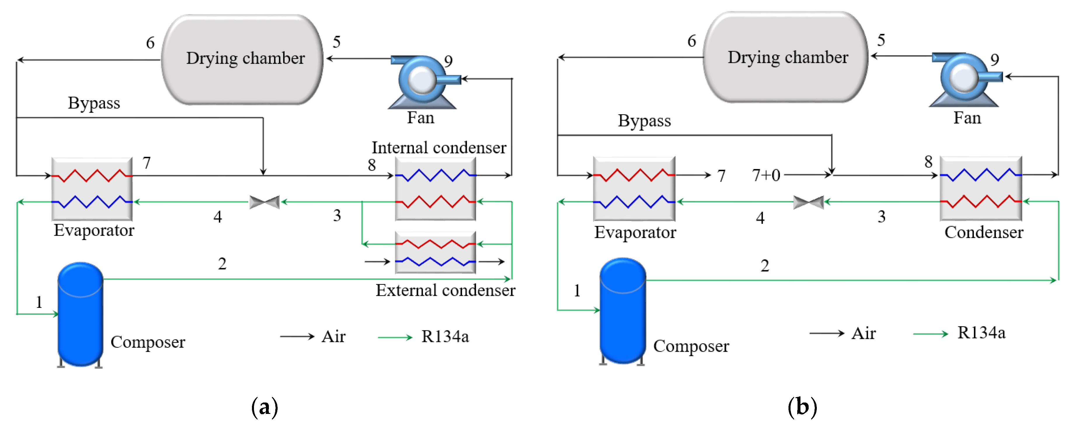
2. System Working Principle
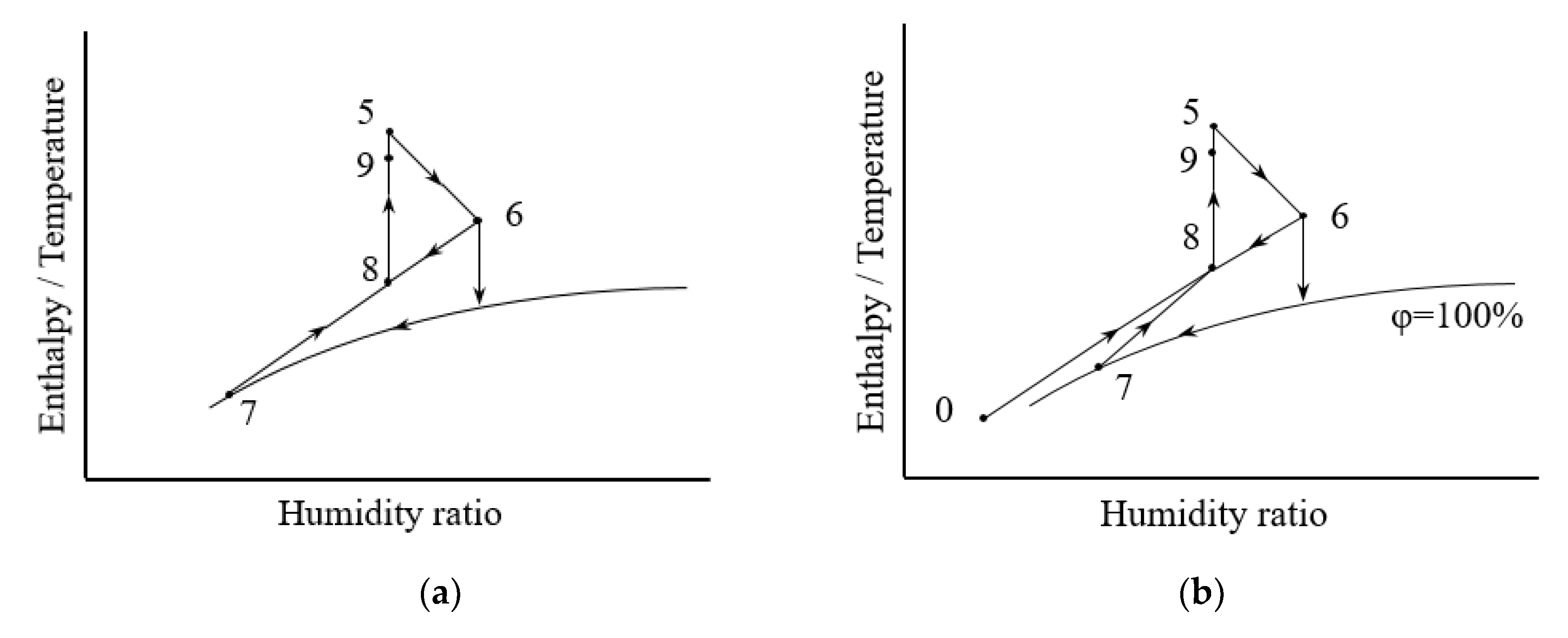
The HPDU proposed is a POHPD designed for the drying applications in cold climate regions, which features the integration of a unit-room to reduce the influence from the ambient conditions, while enhancing the energy efficiency of the heat pump. The working principle of this OHPD system is presented by a comparison with a CHPD as follows:

2.1. Air Cycle

Figure 1 presents the air cycle of the proposed HPDU, together with that of a CHPD for comparison. For the CHPD (see Figure 1a), the air cycle is closed. The air temperature of the dryer is controlled by an additional external condenser to remove the excess heat from the refrigerant, which is equal to the difference between the energy consumption including both fans and compressors, and the sensible heat of the water condensed by the evaporators. The air cycle of the HPDU (see Figure 1b) is partially open which is different from the CHPD. The fresh air (0) is supplied to the system, and the dry air mass flow rate of the fresh air is equal to that of the exhaust air discharged into environment. The fresh air (0), the partial air of the evaporator outlet (7) and the bypass air (6) are mixed in a certain ratio which can be adjusted to control the condition of the supply air into the drying chamber.
Accordingly, the air cycle in Mollier h, Y-chart can be presented as shown in Figure 2. The drying air flows through the drying chamber which is humidified and cooled by the drying materials (i.e., drying products) (5-6). Afterwards, the moist air returns from the drying chamber and then enters the evaporator, where it is dehumidified through condensation. In the CHPD, as shown in Figure 2a, the inlet air (8) of the condenser is mixed by both the outlet air of evaporator (7) and the bypass air (6). For the air cycle of the HPDU (see Figure 2b), which is different from the CHPD, the mixed air (8) consists of the fresh air (0), the partial outlet air of the evaporator (7) and the bypass air (6). The air is heated by a condenser/internal condenser and affected by the power introduced by the fan, corresponding to the isothermal process (8-9-5).

2.2. Refrigerant Cycle
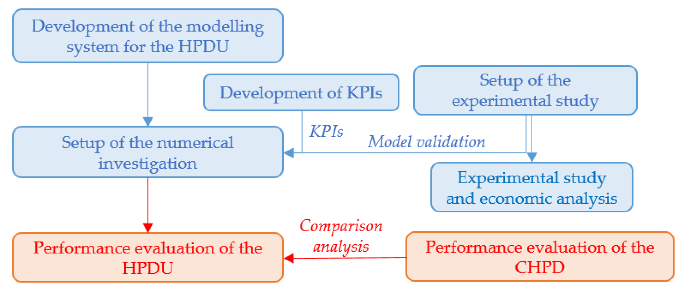
The refrigerant cycle using a pressure-enthalpy diagram was illustrated in Figure 3. For both the CHPD and the HPDU, the refrigerant from the evaporator is first compressed (1–2) by the compressor. It then releases heat to the air in the condenser(s) (2–3) while the refrigerant is cooled to subcooled fluid. Afterwards, the refrigerant is expanded through the throttle valve (3–4) into a mixture of vapor and liquid from the high pressure and temperature, to the low pressure and temperature. The mixture evaporated in the evaporator (4-1) to superheat the vapor after absorbing the heat from the air. It is worthwhile to mention that the pressure drop of the refrigerant in the evaporator and condenser(s) is neglected to simplify the thermal dynamic process of the refrigerant. The temperature profiles of the air and the refrigerant in the evaporator and condenser(s) are presented in Figure 4. The final temperature difference can be assumed to be constant between the air and the refrigerant (δTc and δTe) as suggested by Pal et al. [34].

3. Methodology

The overall methodology used in this study is presented in Figure 5. It started with the development of a modelling system for the HPDU followed by an experimental study based on a practical prototype of the HPDU system. To further facilitate the numerical performance evaluation of the HPDU, the proposed modelling system was first validated using the experimental results, together with the development/selection of a number of key performance indicators (KPIs). Based on the valid modelling system and the KPIs, a series of numerical studies were carried out to investigate the thermal performance of the HPDU under different operation parameters. To quantify the energy benefit of the HPDU, a modelling system for CHPD was also developed and its thermal performance was compared with the HPDU.

3.1. Model Development

A modelling system of the HPDU was developed based on the energy balance and the mass balance of the working fluids (i.e., refrigerant and air) in the refrigerant cycle and the air cycle. It comprised a series of component models, including the drying chamber model, the evaporator model, the condenser model, the mixed-air model, the fan model, the compressor model and the throttle valve model, as detailed in Equations (1)–(21). The following assumptions at the system level were adopted in the model development, according to typical operating conditions, while the assumptions used in each component model were discussed individually.
(1)
The fan power of the external condenser was neglected in the HPD system;
(2)
The system operation was in a steady state;
(3)
The final temperature differences between the air and the refrigerant in the evaporator and condenser(s) were constant, individually; and
(4)
The system was well insulated and the heat loss through the system envelope was neglected.

3.1.1. Drying Chamber Model

The drying process in the drying chamber was considered to be an isenthalpic process as described in Equation (1). Given a total moisture extraction rate (MER) of the drying system, its relationship with the humidity of the supply air and return air of the drying chamber, and the air mass flow rate can be established as presented in Equation (2).
h a , 5 = h a , 6
M E R = 3600 m a , d ( w 6 w 5 )
where h is the enthalpy, m is the mass flow rate, w is the humidity ratio, subscripts a and d indicate the air and the total return air flow from the drying chamber, respectively.

3.1.2. Evaporator Model

The air mass flow of the evaporator was controlled by the bypass factor (BF) which can be determined using Equation (3). The moist air that returned from the drying chamber was cooled and dehumidified by the refrigerant in the evaporator. After passing through the evaporator, the relative humidity of the dehumidified air was assumed to reach 100%, while the temperature of the condensate water was assumed to be the temperature of the air at the evaporator outlet. Accordingly, the enthalpy of the return air and the air at the evaporator outlet can be obtained, as well as the enthalpy of the condensate water, which then can be used to determine the heat transfer rate using Equation (4). Further, based on the humidity of the return air and the air at the evaporator outlet, the moisture extraction rate of the evaporator can be calculated, as described in Equation (5).
B F = m a , d m a , e m a , d
Q e = m a , d ( 1 B F ) ( h a , 6 h a , 7 ) M E R e h e w 3600 = m r ( h r , 1 h r , 4 )
M E R e = 3600 m a , d ( 1 B F ) ( w 6 w 7 )
where Q is the heat transfer rate, subscripts e and ew indicate the evaporator and condensed water, respectively.

3.1.3. Mixed Air Model

The mixed air was a mixture of the air from the evaporator outlet, the bypass air and the ambient fresh air for the HPDU modelling system, which can be described by the energy balance and mass balance, as given in Equations (6) and (7).
( m a , e m a , 0 ) h a , 7 + m a , 0 h a , 0 + ( m a , d m a , e ) h a , 6 = m a , d h a , 8
( m a , e m a , 0 ) w 7 + m a , 0 w 0 + ( m a , d m a , e ) w 6 = m a , d w 8
It was assumed that part of the outlet air from the evaporator was exhausted directly to introduce the fresh air into the unit room. Considering this exchange between the fresh air and the outlet air at the evaporator, the moisture extraction rate of the fresh air can be calculated using Equation (8). Thus, the total moisture extraction rate of the system was the sum of the moisture extraction rates of the fresh air and the evaporator, as given in Equation (9).
M E R 0 = 3600 m 0 ( w 7 w 0 )
M E R = M E R 0 + M E R e
In particular, when the introduction of the ambient fresh air was set to zero, the HPDU modelling system somehow degraded as a CHPD modelling system in terms of the air cycle. Accordingly, the energy balance and mass balance can be described by Equations (10) and (11), and the total moisture extraction rate of the system was equal to the moisture extraction rate of the evaporator, as given in Equation (12).
( 1 B F ) h a , 7 + B F h a , 6 = h a , 8
( 1 B F ) w 7 + B F w 6 = w 8
M E R = M E R e

3.1.4. Condenser Model

The air heating process in the condenser was assumed to be a constant humidity process. The condenser model can be represented by Equations (13) and (14) for the energy balance and mass balance, respectively, in the HPDU modelling system. The humidity of air was also constant in the heating process for the CHPD.
Q c = m a , d ( h a , 9 h a , 8 ) = m r ( h r , 2 h r , 3 )
w 9 = w 8
For a CHPD system without introducing the fresh air, an external condenser was required. Equations (15) and (16) were used to represent the heat released by the condensers.
Q int = m a , d ( h a , 9 h a , 8 )
Q c = Q int + Q e x t = m r ( h r , 2 h r , 3 )
where subscripts int and ext indicate the internal and external condensers, respectively.

3.1.5. Fan Model

The circulation of the air in the drying system was provided by a fan in which the mechanical energy was assumed to be fully converted into internal energy of the air due to flow friction.
E f a n = m a , d ( h a , 5 h a , 9 )
w 5 = w 9
where E is the power.

3.1.6. Compressor Model

The adiabatic efficiency (η) is applied together with the isentropic compression process to simulate the actual power consumption of a compressor [28]. In particular, the isentropic value of the refrigerant at the compressor inlet (hr,1) was obtained through the evaporation temperature, the evaporation pressure and the superheat degree. The enthalpy of the refrigerant at the compressor outlet (hr,2) was determined based on the isentropic curve and condensing pressure. The enthalpy difference (δh) of the refrigerant was obtained along the isentropic curve.
E c o m p = m r δ h η = m r ( h r , 2 h r , 1 )
where η is the adiabatic efficiency of the compressor which is defined as the ratio of δh divided by the enthalpy difference (hr,2-hr,1) between the refrigerant at the inlet and the outlet of the compressor in the actual compression process [17] (see Equation (20)), and usually is provided by the manufacture, determined through practical measurement, or set as a common assumed value. The subscripts comp and r indicate the compression and the refrigerant, respectively.
η = δ h h r , 2 h r , 1

3.1.7. Throttle Valve Model

The expansion process of the refrigerant when passing through the throttle valve was assumed to be adiabatic. According to the first law of thermodynamics, the energy balance can be described in Equation (21).
h r , 3 = h r , 4
The above component models were coupled as a modelling system for the HPDU in the engineering equation solver (EES) platform. By using this modelling system, the influencing factors, such as the ambient air temperature and the BF, can be analyzed to investigate their influence on system performance based on the psychrometric characteristics of the moist air and the thermal physical properties of the refrigerant. Despite its simplicity, the modelling system was able to capture the main performance characteristics of the HPDU while avoiding the complexity introduced by practical disturbances (e.g., the starting process etc.), thereby facilitating the better understanding of the system’s energy performance. It is worthwhile to note that the modelling system is not perfect and there exist inherent limitations when used in numerical performance analysis: (1) It cannot be used to evaluate the drying process with significant parameter/condition variations; (2) it is based on a number of assumptions which need to be double checked and revised based on the practical system operation.

3.2. Development of the Key Performance Indicators

A number of key performance indicators (KPIs) were developed to facilitate the system performance assessment including the moisture extraction rate (MER), the specific moisture extraction rate (SMER) and the coefficient of performance (COP) which were defined by Equations (22–25), respectively. These KPIs have been extensively used to evaluate the energy efficiency of a HPD in public domain references.
The SMER was defined as the ratio of water evaporated from products to the total energy consumption (TEC) in the whole drying process [34].
S M E R = M E R T E C
T E C = E c o m p + E f a n
The coefficient of performance (COP) is another parameter to represent the performance of the heat pump dryers, and it was obtained with the relation defined using Equations (24) and (25) for the HPDU and CHPD, respectively.
C O P = Q c + E f a n T E C
C O P = Q int + E f a n T E C

3.3. Experimental System

The design of the HPDU was presented in Figure 6. The dimension of the HPDU system was 12.30 m (length) × 3.60 m (width) × 2.74 m (height), which can be divided into the drying chamber with a size of 9.20 m (length) × 3.60 m (width) × 2.74 m (height), and the unit-room with the size of 2.10 m (length) × 3.60 m (width) × 2.15 m (height). The unit-room was not only used for fresh air introduction and mixing, but also served as the main equipment room where the dampers No.1–4, as well as the major parts of the heat pumps were installed. The heat pumps had a total capacity of 14HP, in which the compressors, evaporators, evaporator fans, and throttle valves, etc. were installed in the unit-room, while the condensers and the electric heaters were installed between the bypass channel and the drying chamber.
The return air from the drying chamber was drawn into the unit-room and the bypass channel, whose distribution fraction (i.e., BF) was controlled by damper No.1. The return air drawn into the unit-room was cooled and dehumidified by the evaporators, and then exhausted to the environment through damper No.3. The fresh air was introduced into the unit-room and controlled by damper No.2. The fresh air and the part of the air from the evaporator outlet were mixed and introduced into the bypass channel through damper No.4. The air from the unit-room and the bypass air were mixed in the bypass channel before entering the condenser. After the mixed air was heated by the condenser, the hot air was supplied into the drying chamber for material drying.
A number of temperature and humidity sensors were installed in the drying chamber, the unit-room and the heat pumps to monitor the conditions of the air and refrigerant. The temperature and humidity of the air were measured by the Temperature and Humidity Transmitter (JWSK-6, ±1 °C, ±3%), and the testing points (a, b, c and d) were shown in Figure 6a. The testing points (a, b, c, d) were located on the symmetrical surfaces of the heat pump dryer. The testing points (a, b, c) were placed in the central position of the drying chamber along the high direction, and the testing points (d) in the central position of the unit-room along the high direction. The distance between the testing points (a, b, c) was 0.60 m and the distance from the testing point (c) to the ground was 0.4 m. The distance between the testing point (d) and the ground was 2.00 m. The temperature of the refrigerant (1, 2, 3 and 4) was measured by the Thermocouple (KLH 1001K, ±1.5 °C), which were fixed on the surface of the copper tube coated with the thermal conductive silicone grease and well-insulated outside. The power consumption of the components, such as the compressors, fans and the electric heater, were determined using the measured voltage and current of these devices. The data were collected by the Data Acquisition Instrument (Agilent).

3.4. Setup of the Experiment and Modelling

3.4.1. Setup of the Experiment

The experimental performance of the HPDU was tested through a drying experiment on Xinjiang Hetiandazao [35] (i.e., red jujubes). The drying experiment was carried out under the ambient temperature of 0–15 °C. The drying temperature was set as 56 °C based on previous studies [36,37]. The fresh red jujubes with a total mass of around 6.75 kg were distributed evenly on a number of pallets which were then assembled as 8 movable racks consisting of 384 pallets in total. The heat pump dryer started with a closed-loop operation mode without introducing fresh air during the preheating process by closing dampers No.2 and No.3 while leaving dampers No.1 and No 4 open. Meanwhile, the fans, the heat pumps and the electric heaters were switched on. When the temperature of the air in the drying chamber reached the setting value, the electric heaters were switched off and the system was switched to a partially open-loop operation mode. The heat pumps and the dampers of the unit-room were adjusted according to the air conditions in the drying chamber. Specifically, the air temperature in the drying chamber was controlled within 56 ± 2 °C through the on-off of the heat pumps, while the air humidity in the drying chamber was controlled by the on-off of the dampers in the unit-room. The moisture was extracted by the evaporators of the heat pumps and the exhaust air. The system was switched off when the red jujubes were dried to the required quality.

3.4.2. Setup of the Modelling

It has been reported that a drying process can be considered as a steady state to simplify its modelling [28,34]. The drying process in this study was therefore assumed to be a steady state with constant ambient and drying conditions. Corresponding to the experiments, the key parameters of the system were used in the modelling as summarized in Table 1 The parameters used in the modelling were mainly achieved from the experimental study by averaging the experimental parameters during the experiment, including η, refrigerant, δtc, δte, supply air conditions, ambient relative humidity (rh0), MER, the circulating fan and the work input of the evaporator fan. Some other parameters for the modelling, including subcooling degree, superheat degree, and ambient temperature (t0), were assumed values.
To gain a clear insight of the system operation characteristics for the HPDU, a series numerical cases were designed and studied as summarized in Table 2. For the sake of comparison, a number of numerical cases for the HPDU under different ambient temperatures were first studied, together with a numerical case designed for the CHPD as the benchmark. In each case, the system performance varying with the BF was also investigated.

4. Results and Discussion

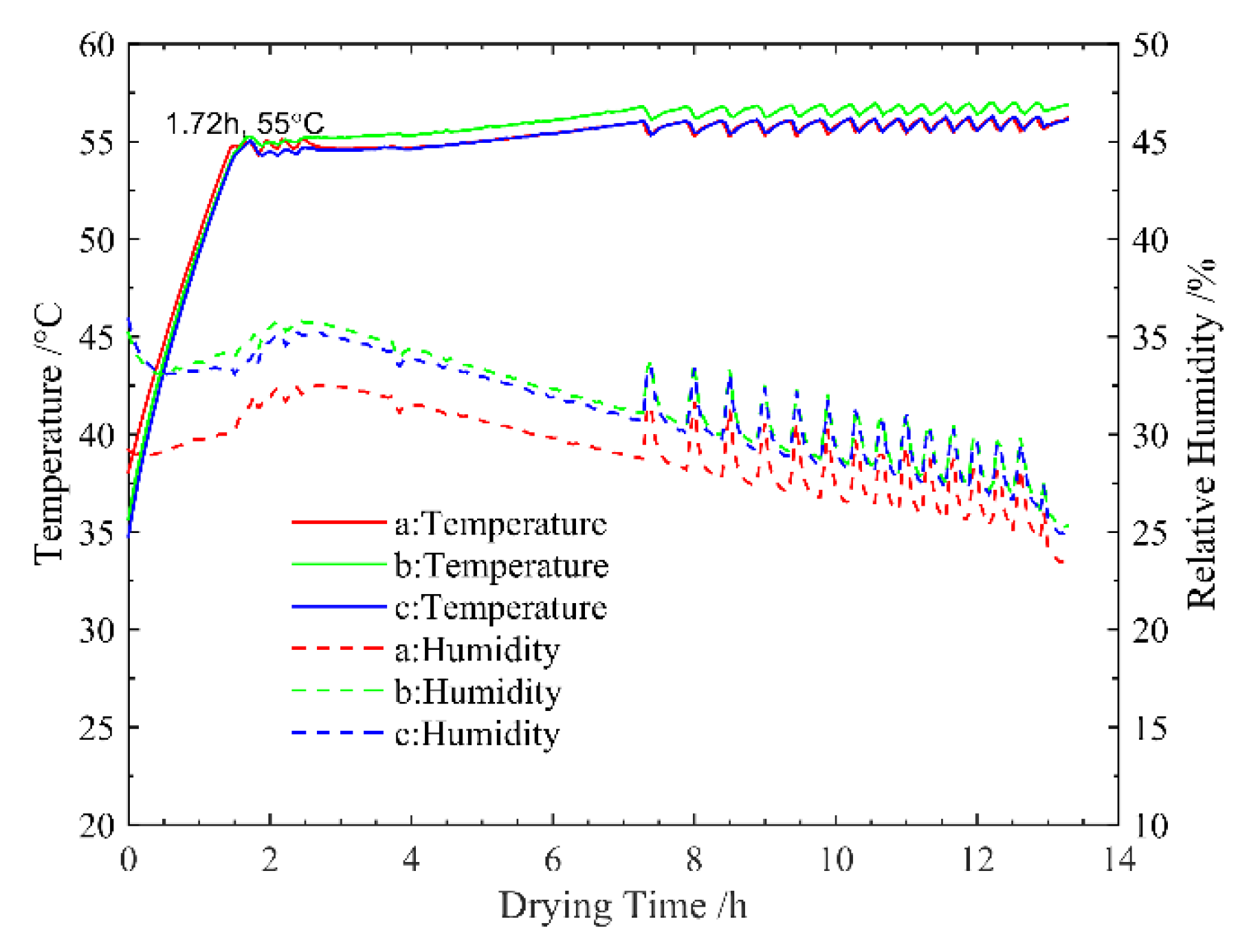
4.1. Experimental Results

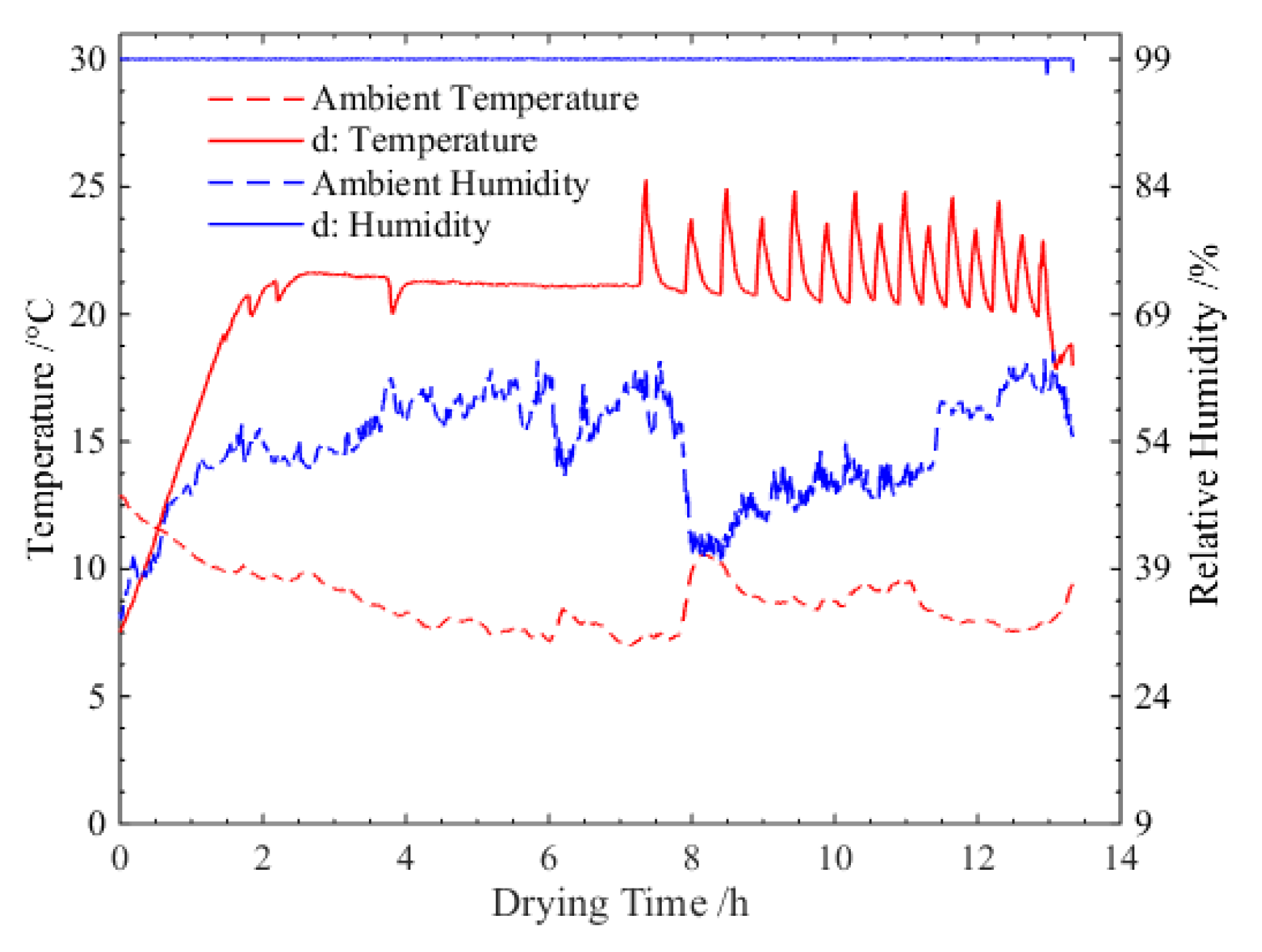
4.1.1. The Air Conditions in the Drying Chamber

Figure 7 shows the profiles of the temperature and relative humidity of the air in the drying chamber during the drying process. It can be seen that the air temperature in the drying chamber was successfully controlled within 56 ± 2 °C. The preheating time required for the air to reach 55 °C was approximately 1.72 h, which accounted for approximately 13% of the total drying period. At approximately 7 h of the drying process, the intermittent on-off of the compressor resulted in the fluctuations of the temperature and relative humidity of the air in the drying chamber. The maximum air temperature deviation from the setting temperature was small and only up to 1.83 °C, presenting a relatively stable air temperature drying process. The maximum temperature difference among the testing points a, b and c was 1.2 °C in the vertical direction of the drying chamber indicating an excellent air flow organization in the drying chamber. Due to the moisture extraction during the drying process, the air humidity in the drying chamber gradually declined from approximately 34% to 29%.

4.1.2. The Air Conditions in the Unit-Room

Figure 8 presents the temperature and humidity of the ambient air and the air in the unit-room during the drying process. It can be found that the temperature and humidity of the air in the unit-room were much higher than the ambient air. Basically, a relative stable air condition was achieved in the unit-room, despite the significant variation of the ambient temperature and humidity. The relative humidity of the air in the unit-room was stabilized at approximately 99.04%, while the corresponding air temperature fluctuated at approximately 22 °C due to the on-off control of the heat pump system. Accordingly, it can be concluded that the unit-room integrated in the system was useful to provide a stable operation condition for the HPD to avoid the influence from the ambient conditions.

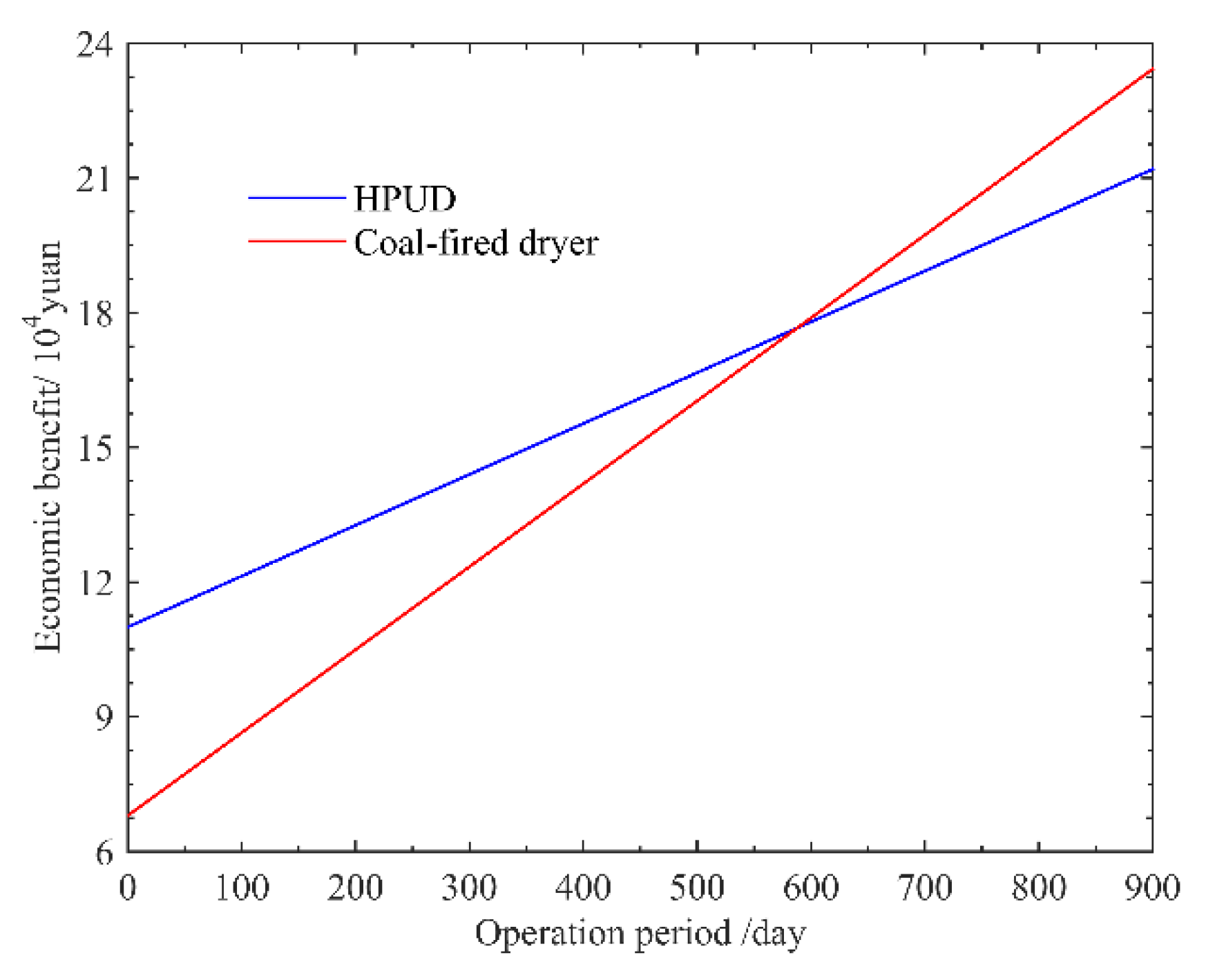
4.1.3. Economic Analysis

Table 3 summarized the final experimental data together with a simple economic analysis. The average MER of the system was 29.47 kg/h based on the mass difference of the red jujubes before and after drying as well as the drying time, while the corresponding energy consumption of the system was 236.8 kW·h. Accordingly, the average SMER of the system reached 1.64 kg/(kW·h) in the experimental study.
The above final experimental data were economically compared with a traditional coal-fired dryer. Considering the electricity price of 0.58 yuan/(kW·h), the drying cost of the dried red jujube per ton was 62.3 yuan/t (see Table 3). As a comparison, a traditional coal-fired dryer with the same drying capacity and under the same drying conditions consumed approximately 0.24 t coal to produce the same amount of dried red jujubes whose unit drying coast reached approximately 101.6 yuan/t (see Table 3). Even though the initial coast of the HPDU was higher than the coal-fired dryer (i.e., 110 thousand yuan and 68 thousand yuan, respectively), the unit drying cost of the HPDU was reduced by 38.7% compared to using the coal-fired dryer. Assuming that both the HPDU and the coal-fired drying could operation 24 h per day, the overall economic benefit of using HPDU for the red jujube drying could outperform the coal-fired dryer after 588 days as shown in Figure 9.

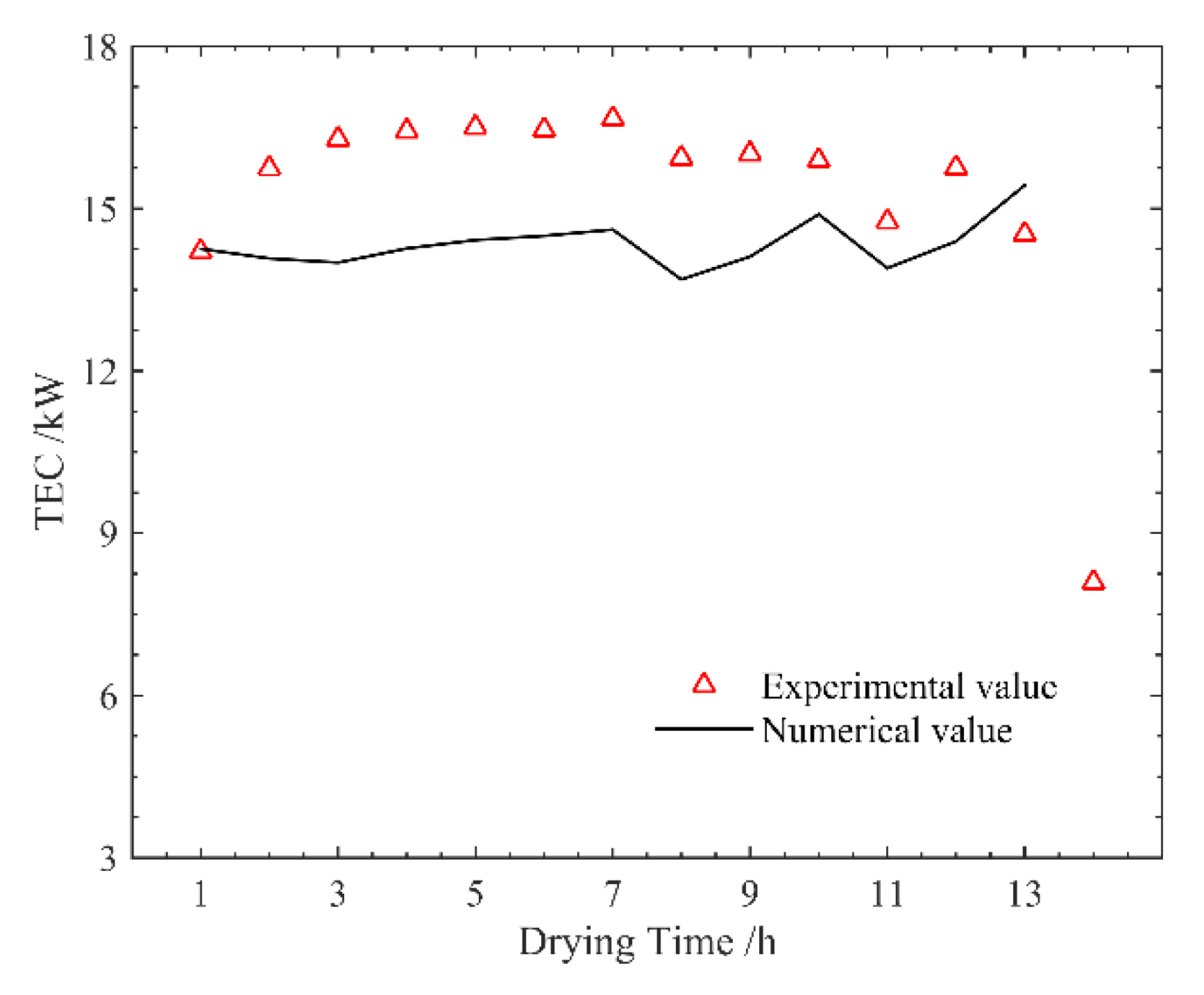
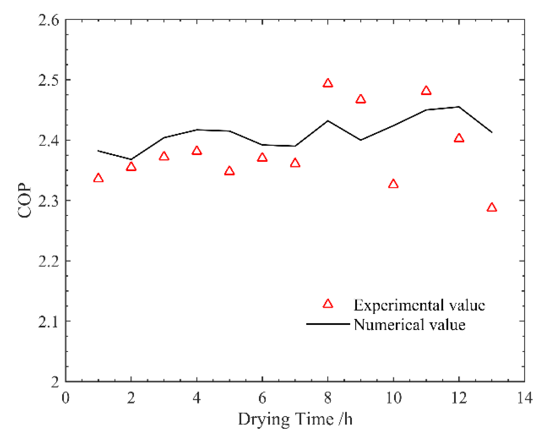
4.2. Validation of the Modelling System

The experimental results in terms of the TEC and COP were measured and used to validate the modelling system of the HPDU. Note that in the model validation, almost all the parameters used were from Table 1, except for the conditions of the supply air in the drying chamber (i.e., temperature and humidity) whose values derived from the instantaneous experimental measurement. This is the reason why the numerical results varied with the time corresponding to the experimental measurement. Figure 10 compares the measured TEC with the calculated value using the modelling system. It can be seen that the measured TEC of the system ranged from 14.20 kW to 16.66 kW, which averaged at approximately 15.78 kW during the experiment. Correspondingly, the calculated TEC fluctuated between 13.69 kW and 15.43 kW with an average value of approximately 14.35 kW. The root mean square error (RMSE) between the experimental and numerical values of the TEC was 1.71. This deviation may be due to the heat loss of the system.
Figure 11 further compared the measured COP with the COP numerically calculated using the modelling system. It can be found that an acceptable agreement between the calculated COP and the experimental measurement was achieved. The measured COP and the calculated COP ranged from 2.29 to 2.49 and from 2.37 to 2.46, respectively, and the corresponding RMES value was only 0.06. Based on the above discussion, it can be concluded that the modelling system can provide a reliable prediction of energy efficiency for the practical system performance, and it therefore can be used for the further numerical performance analysis of the HPDU.

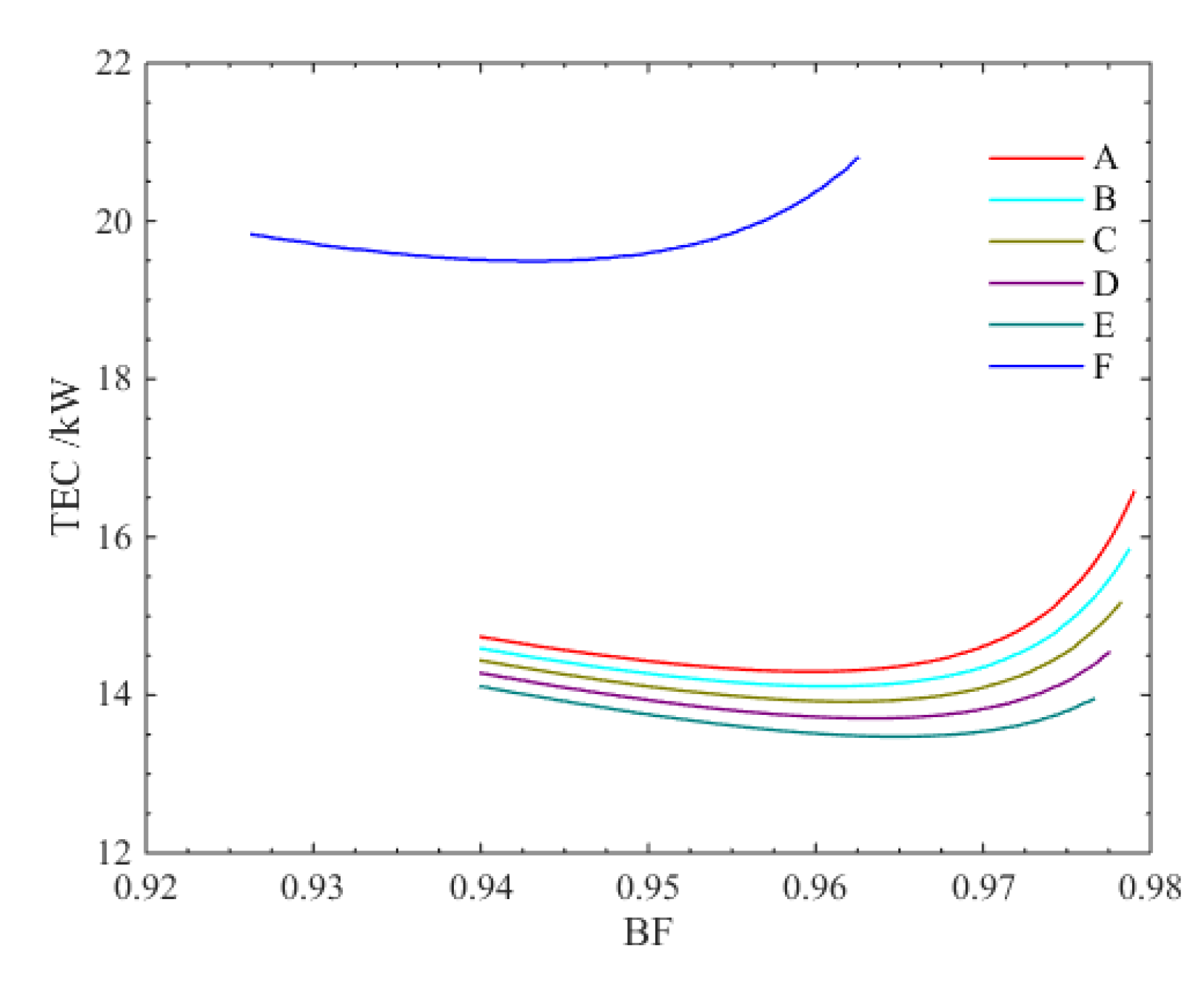
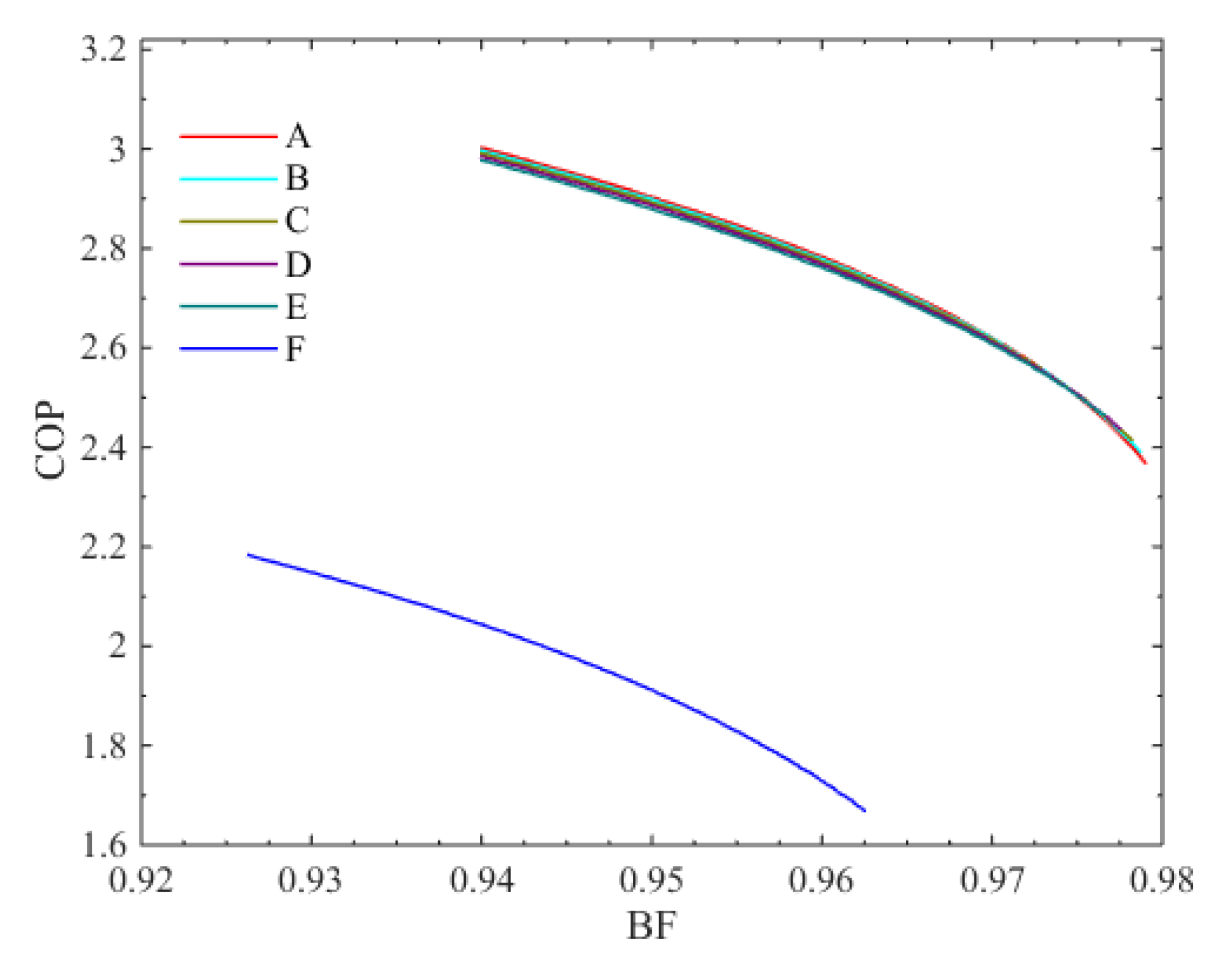
4.3. Numerical Results

Figure 12 presents the variations of SMER with the increasing BF for different cases. It can be seen that for both the HPDU (i.e., Cases A-E) and the CHPD (i.e., Case F), the corresponding SMER first increased and then decreased with the increasing BF, where a maximum existed for each case. However, being different from Case F without the ambient influence, a higher SMER can generally be found under a higher ambient temperature for the HPDU. With the increasing of the ambient temperature, the BF corresponding to the maximal SMER slightly increased. When the ambient air temperature was 10 °C (i.e., Case E), the maximal SMER reached 2.23 kg/(kW·h) with a BF of 96.51%, which was much higher than the CHPD (i.e., Case F) of 1.54 kg/(kW·h) with a BF of 94.38%. Compared to Case F, the maximal SMER of the system can be improved by 36.32%–44.64% in the HPDU depending on the ambient temperature.
Figure 13 further presents the variations of the TEC with the increasing BF for different cases. The corresponding TEC decreased first and then increased when increasing the BF. Similar to that of the SMER, a great difference can be found between Case F and Cases A-E, presenting a much lower TEC for the HPDU compared to the CHPD. The TEC can be reduced by up to 30.87% in comparison to the benchmark (i.e., Case F). With increasing the ambient temperature (i.e., Cases A-E), the TEC of the HPDU experienced a decreasing trend.
Figure 14 shows the COP for each case as a function of BF. It can be found that the system types significantly affected the energy efficiency of the drying process in which the HPDU outperformed the CHPD due to its much higher COP. However, the ambient temperature only had a slight impact on the COP of both heat pump drying systems. The COP experienced a decreasing trend in each case, and a maximal COP did not correspond to the maximal SMER (see Figure 11). When the BF corresponding to the maximal SMER was adopted, the COP can reach 2.79 for Case A, while the CHPD (i.e., Case F) was only approximately 2.00. Compared to the benchmark (i.e., Case F), the COP corresponding to the maximal SMER can be improved by up to 39.56%.

5. Conclusions

A novel partially open-loop heat pump dryer with a unit-room (HPDU) was proposed and developed to improve the energy efficiency of the heat pump drying process under cold climate applications. The HPDU featured a unit-room which was designed to introduce fresh air and mix the air for system energy efficiency enhancement while avoiding the direct influence of ambient conditions on system performance. A modelling system of the HPDU was developed and validated based on a real-scale experimental study. A series of numerical studies were then carried out to characterize the system performance by comparison with a closed-loop heat pump dryer (CHPD).
It was found that the unit-room can provide a relatively stable air condition for the drying process. There was an optimal bypass factor (BF) in each numerical study under a certain ambient air temperature corresponding to a maximal specific moisture extraction rate (SMER) where the lowest total energy consumption (TEC) can also be achieved. By comparison to the CPHD, the SMER and the TEC increased and decreased by up to 44.64% and 30.87%, respectively for the HPDU. By using the optimal BF, the corresponding coefficient of performance (COP) can reach 2.79 maximum for the HPDU, compared to only 2.0 in the CHPD. Even though the ambient temperature had a considerable influence on the SMER and TEC of the system, it only slightly affected the system’s COP. It demonstrated that the HPDU outperformed the CHPD in terms of energy efficiency, and it was effective in utilizing the unit-room for performance enhancement of HPDs.

Author Contributions

Conceptualization, Y.Y. and L.Y.; Methodology, W.L. (Weizhao Li); Software, Y.Y.; Validation, Y.Y. and W.L. (Weizhao Li); Formal Analysis, Y.Y.; Investigation, Y.Y., W.L. (Weizhao Li), W.L. (Weizhao Li) and X.M.; Resources, Y.Y.; Data Curation, Y.Y.; Writing-Original Draft Preparation, Y.Y.; Writing-Review & Editing, W.L. (Wenye Lin), B.X.; Visualization, Y.Y. and W.L. (Weizhao Li); Supervision, L.Y.; Project Administration, L.Y. and J.W.; Funding Acquisition, L.Y.

Funding

This research was funded by National Key R&D Plan of China grant number 2018YFD0700205.

Conflicts of Interest

The authors declare no conflict of interest.

Nomenclature

BFBypass factor
EEnergy consumptions [kW]
δhEnthalpy change of refrigerant at isentropic compression [kJ/kg]
hEnthalpy [kJ/kg]
mMass flow rate[kg/s]
MERMoisture extraction rate of the dryer [kg/h]
QHeat transfer rate [kW]
rhAir relative humidity [%]
tTemperature [°C]
δtThe temperature difference between the air and the refrigerant [°C]
wHumidity ratio of air [kg water/kg]
Greek Symbols
ηAdiabatic efficiency of compressor
Subscripts
aDrying air
dDrying air of the dryer outlet
cCondenser
compCompressor
eEvaporator
ewWater condensed by the evaporator
extExternal condenser
fanCirculating fan
intInternal condenser
rRefrigerant

References

  1. Mujumdar, A.S.; Huang, L.X. Global R&D Needs in Drying. Dry. Technol. 2007, 25, 647–658. [Google Scholar]
  2. Minea, V. Drying heat pumps-part I: System integration. Int. J. Refrig. 2013, 36, 643–658. [Google Scholar] [CrossRef]
  3. Wang, Z.; Zhang, Y.; Zhang, B.; Yang, F.; Yu, X.; Zhao, B.; Wei, Y. Analysis on energy consumption of drying process for dried Chinese noodles. Appl. Therm. Eng. 2017, 110, 941–948. [Google Scholar] [CrossRef]
  4. Yang, Z.; Zhu, Z.; Zhao, F. Simultaneous control of drying temperature and superheat for a closed-loop heat pump dryer. Appl. Therm. Eng. 2016, 93, 571–579. [Google Scholar] [CrossRef]
  5. Singh, A.; Sarkar, J.; Sahoo, R.R. Energetic and exergetic performance simulation of open-type heat pump dryer with next-generation refrigerants. Dry. Technol. 2019, 1–13. [Google Scholar] [CrossRef]
  6. Liu, Y.; Zhao, K.; Jiu, M.; Zhang, Y. Design and drying technology research of heat pump Lentinula edodes drying room. Procedia Eng. 2017, 205, 983–988. [Google Scholar] [CrossRef]
  7. Singh, A.; Sarkar, J.; Sahoo, R.R. Comparative analyses on a batch-type heat pump dryer using low GWP refrigerant. Food Bioprod. Process. 2019, 117, 1–13. [Google Scholar] [CrossRef]
  8. Liu, H.; Yousaf, K.; Chen, K.; Soomro, S. Design and thermal analysis of an air source heat pump dryer for food drying. Sustainability 2018, 10, 3216. [Google Scholar] [CrossRef]
  9. Taşeri, L.; Aktaş, M.; Şevik, S.; Gülcü, M.; Seçkin, G.U.; Aktekeli, B. Determination of drying kinetics and quality parameters of grape pomace dried with a heat pump dryer. Food Chem. 2018, 260, 152–159. [Google Scholar] [CrossRef] [PubMed]
  10. TeGrotenhuis, W.; Butterfield, A.; Caldwell, D.; Crook, A.; Winkelman, A. Modeling and design of a high efficiency hybrid heat pump clothes dryer. Appl. Therm. Eng. 2017, 124, 170–177. [Google Scholar] [CrossRef]
  11. Aktaş, M.; Taşeri, L.; Şevik, S.; Gülcü, M.; Uysal Seçkin, G.; Dolgun, E.C. Heat pump drying of grape pomace: Performance and product quality analysis. Dry. Technol. 2019, 1–14. [Google Scholar] [CrossRef]
  12. Rahman, S.M.A.; Saidur, R.; Hawlader, M.N.A. An economic optimization of evaporator and air collector area in a solar assisted heat pump drying system. Energy Convers. Manag. 2013, 76, 377–384. [Google Scholar] [CrossRef]
  13. Pal, U.S.; Khan, M.K. Performance evaluation of heat pump dryer. J. Food Sci. Technol. 2010, 47, 230–234. [Google Scholar] [CrossRef] [PubMed] [Green Version]
  14. Siva, A.; Somchart, S.; Apichit, T. Mathematical model development and simulation of heat pump fruit dryer. Dry. Technol. 2000, 18, 479–491. [Google Scholar] [CrossRef]
  15. Hakkaki-Fard, A.; Aidoun, Z.; Ouzzane, M. Applying refrigerant mixtures with thermal glide in cold climate air-source heat pumps. Appl. Therm. Eng. 2014, 62, 714–722. [Google Scholar] [CrossRef]
  16. Song, M.; Gong, G.; Mao, N.; Deng, S.; Wang, Z. Experimental investigation on an air source heat pump unit with a three-circuit outdoor coil for its reverse cycle defrosting termination temperature. Appl. Energy 2017, 204, 1388–1398. [Google Scholar] [CrossRef]
  17. Shen, J.; Guo, T.; Tian, Y.; Xing, Z. Design and experimental study of an air source heat pump for drying with dual modes of single stage and cascade cycle. Appl. Therm. Eng. 2018, 129, 280–289. [Google Scholar] [CrossRef]
  18. Şevik, S.; Aktaş, M.; Doğan, H.; Koçak, S. Mushroom drying with solar assisted heat pump system. Energy Convers. Manag. 2013, 72, 171–178. [Google Scholar] [CrossRef]
  19. Sevik, S. Experimental investigation of a new design solar-heat pump dryer under the different climatic conditions and drying behavior of selected products. Sol. Energy 2014, 105, 190–205. [Google Scholar] [CrossRef]
  20. Colak, N.; Hepbasli, A. A review of heat-pump drying (HPD): Part 2–Applications and performance assessments. Energy Convers. Manag. 2009, 50, 2187–2199. [Google Scholar] [CrossRef]
  21. Coşkun, S.; Doymaz, I.; Tunçkal, C.; Erdoğan, S. Investigation of drying kinetics of tomato slices dried by using a closed loop heat pump dryer. Heat Mass Transf. 2016, 53, 1–9. [Google Scholar] [CrossRef]
  22. Zhu, E. Experimental research on parallel conversion control of drying temperature in a closed-loop heat pump dryer. Dry. Technol. 2013, 31, 1049–1055. [Google Scholar]
  23. Senadeera, W.; AlvesFilho, O.; Eikevik, T. Influence of atmospheric sublimation and evaporation on the heat pump fluid bed drying of bovine intestines. Dry. Technol. 2012, 30, 1583–1591. [Google Scholar] [CrossRef]
  24. Zielinska, M.; Zapotoczny, P.; Alves-Filho, O.; Eikevik, T.M.; Blaszczak, W. A multi-stage combined heat pump and microwave vacuum drying of green peas. J. Food Eng. 2013, 115, 347–356. [Google Scholar] [CrossRef]
  25. Li, W.; Sheng, W.; Zhang, Z.; Yang, L.; Zhang, C.; Wei, J.; Li, B. Experiment on performance of corn drying system with combination of heat pipe and multi-stage series heat pump equipment. Trans. Chin. Soc. Agric. Eng. 2018, 33, 278–284. [Google Scholar]
  26. Wei, J.; Yang, L.; Zhang, Z. Simulation and application of continuous corn drying tower of dehumidified heat pump. J. China Agric. Univ. 2018, 23, 114–119. [Google Scholar]
  27. Alvesfilho, O.; Eikevik, T.M. Heat pump drying kinetics of Spanish cheese. Int. J. Food Eng. 2008, 4, 99–107. [Google Scholar]
  28. Lee, K.H.; Kim, O.J.; Kim, J. Performance simulation of a two-cycle heat pump dryer for high-temperature drying. Dry. Technol. 2010, 28, 683–689. [Google Scholar] [CrossRef]
  29. Tunçkal, C.; Coşkun, S.; Doymaz, İ. Determination of sliced pineapple drying characteristics in a closed loop heat pump assisted drying system. Int. J. Renew. Energy Dev. 2018, 7, 35–41. [Google Scholar] [CrossRef]
  30. Shengchun, L.; Xueqiang, L.; Mengjie, S.; Hailong, L.; Zhili, S. Experimental investigation on drying performance of an existed enclosed fixed frequency air source heat pump drying system. Appl. Therm. Eng. 2018, 130, 735–744. [Google Scholar] [CrossRef]
  31. Chapchaimoh, K.; Poomsa-ad, N.; Wiset, L.; Morris, J. Thermal characteristics of heat pump dryer for ginger drying. Appl. Therm. Eng. 2016, 95, 491–498. [Google Scholar] [CrossRef]
  32. Duan, Q.; Wang, D.; Li, X.; Li, Y.; Zhang, S. Thermal characteristics of a novel enclosed cascade-like heat pump dryer used in a tunnel type drying system. Appl. Therm. Eng. 2019, 155, 206–216. [Google Scholar] [CrossRef]
  33. Ziegler, T.; Jubaer, H.; Mellmann, J. Simulation of a heat pump dryer for medicinal plants. Chem. Ing. Tech. 2013, 85, 353–363. [Google Scholar] [CrossRef]
  34. Pal, U.S.; Khan, M.K. Calculation steps for the design of different components of heat pump dryers under constant drying rate condition. Dry. Technol. 2008, 26, 864–872. [Google Scholar] [CrossRef]
  35. Chen, J.; Li, Z.; Maiwulanjiang, M.; Zhang, W.L.; Zhan, J.Y.; Lam, C.T.; Dong, T.T.; Lau, D.T.W.; Choi, R.C.Y.; Yao, P.; et al. Chemical grape pomace and biological assessment of ziziphus jujuba fruits from china: Different geographical sources and developmental stages. J. Agric. Food Chem. 2013, 61, 7315–7324. [Google Scholar] [CrossRef] [PubMed]
  36. Chen, Q.; Bi, J.; Wu, X.; Yi, J.; Zhou, L.; Zhou, Y. Drying kinetics and quality attributes of jujube (Zizyphus jujuba, Miller) slices dried by hot-air and short-and medium-wave infrared radiation. LWT-Food Sci. Technol. 2015, 64, 759–766. [Google Scholar] [CrossRef]
  37. Yang, X.; Xie, Y.; Jin, G. Improved scheme and test comparison of drying jujube date using heat pump. Trans. CSAE 2009, 25, 329–332. [Google Scholar]
  38. Available online: http://xinjiangxisheng.21food.cn/ (accessed on 13 September 2017).
Figure 1. Schematic diagram of the system showing air and refrigerant cycles for: (a) The CHPD, (b) the HPDU.
Energies 12 03125 g001
Figure 2. Mollier h, Y-chart showing air cycle in drying chamber for: (a) the CHPD, (b) the HPDU.
Energies 12 03125 g002
Figure 3. Pressure-enthalpy diagram of a refrigerant cycle in a heat pump.
Energies 12 03125 g003
Figure 4. The temperature profile of the air and the refrigerant.
Energies 12 03125 g004
Figure 5. Research methodology used in this study.
Energies 12 03125 g005
Figure 6. The novel partially open-loop heat pump dryer with the unit-room: (a) Schematic diagram; (b) practical prototype.
Energies 12 03125 g006
Figure 7. Temperature and humidity of drying chamber.
Energies 12 03125 g007
Figure 8. The temperature and relative humidity of the unit-room.
Energies 12 03125 g008
Figure 9. A comparative analysis of the economic benefit.
Energies 12 03125 g009
Figure 10. Energy consumption of the heat pumps.
Energies 12 03125 g010
Figure 11. The coefficient of performance (COP) of the system in the course of the drying process.
Energies 12 03125 g011
Figure 12. The effect of the bypass factor (BF) on specific moisture extraction rates (SMER).
Energies 12 03125 g012
Figure 13. The effect of BF on total energy consumption (TEC).
Energies 12 03125 g013
Figure 14. The effect of BF on COP.
Energies 12 03125 g014
Table 1. Setting parameters.
ParametersValue
RefrigerantR134a
η0.61
δtc8 °C
δte8 °C
Subcooling degree5 °C
Superheat degree5 °C
Supply air conditions56 °C/30%
t0−10, −5, 0, 5, 10 °C
rh050%
MER30 kg/h
Circulating fan4.4 kW/40,000 m3/h
Work input of evaporator fan1.0 kW
Table 2. Summary of the numerical cases.
CaseSystem Typet0 (°C)
AHPDU−10
BHPDU−5
CHPDU0
DHPDU5
EHPDU10
F (Benchmark)CHPD-
Table 3. The economic analysis of the system.
ParameterHPDUCoal-Fired Dryer [38]
Fresh red jujube (kg)2592
Dried red jujube (kg)2203
Drying time (h)13.2
Energy consumption of circulation fan (kW·h)59.426
Energy consumption of electric heater (kW·h)230
Energy consumption of the system(kW·h)236.826
Electricity price yuan/(kW·h)0.58
Price of coal (yuan/t)870
Consumption of coal (t)00.24
Dried cost (yuan/t)62.3101.6
SMER (kg/(kW·h))1.64-

