Article

Electrical Treeing in Power Cable Insulation under Harmonics Superimposed on Unfiltered HVDC Voltages

by
Mehrtash Azizian Fard
1,*,
Mohamed Emad Farrag
2,3,
Alistair Reid
4 and
Faris Al-Naemi
1
1
Department of Engineering and Mathematics, Sheffield Hallam University, Sheffield S1 1WB, UK
2
Department of Engineering, Glasgow Caledonian University, Glasgow G4 0BA, UK
3
Faculty of Industrial Education, Helwan University, 11795 Helwan, Egypt
4
School of Engineering, Cardiff University, Cardiff CF10 3AT, UK
*
Author to whom correspondence should be addressed.
Energies 2019, 12(16), 3113; https://doi.org/10.3390/en12163113
Submission received: 28 June 2019 / Revised: 13 August 2019 / Accepted: 13 August 2019 / Published: 14 August 2019

Abstract

:
Insulation degradation is an irreversible phenomenon that can potentially lead to failure of power cable systems. This paper describes the results of an experimental investigation into the influence of direct current (DC) superimposed with harmonic voltages on both partial discharge (PD) activity and electrical tree (ET) phenomena within polymeric insulations. The test samples were prepared from a high voltage direct current (HVDC) cross linked polyethylene (XLPE) power cable. A double electrode arrangement was employed to produce divergent electric fields within the test samples that could possibly result in formation of electrical trees. The developed ETs were observed via an optical method and, at the same time, the emanating PD pulses were measured using conventional techniques. The results show a tenable relation between ETs, PD activities, and the level of harmonic voltages. An increase in harmonic levels has a marked effect on development of electrical trees as the firing angle increases, which also leads to higher activity of partial discharges. This study of the influencing operational parameters of HVDC converters on power cable insulation is predicted to contribute to enhancements in cable design and progressive advancement in condition monitoring and insulation diagnostic techniques that can lead to more effective asset management in HVDC systems.

1. Introduction

High Voltage DC (HVDC) power cables are some of the main components of power transmission in offshore renewable integrations, cross-country interconnections and HVDC grids [1]. Since the introduction of XLPE DC cables at commercial scale, which was first used in the Gotland project in Sweden in 1998, these cables have been mainly employed in voltage source converter (VSC) based HVDC systems. Under such HVDC schemes, as opposed to line commutated converter (LCC) systems, there would be no necessity for the change of voltage polarity to alter the power flow direction. Therefore, XLPE power cables would not experience polarity reversal in VSC HVDC systems. In addition, employment of environmentally friendly power cables and the technological advancements in terms of cable design, material, and manufacturing technologies are amongst the incentives to adopt polymeric cables in HVDC power transmission. Such cables can potentially operate in LCC schemes as well, where transmission of large amount of power is feasible [2,3].
In comparison to high voltage alternating current (HVAC) power cables, XLPE DC cables are still at their early stages of development, with ongoing research and investigation into the long-term behavior, ageing, and degradation of polymeric based power cables through accelerated test methods [4] under non-pure DC voltage operations. Deterioration of cable insulation is an irreversible phenomenon that generally starts off from the weak regions within the insulation systems and, depending upon the type and the severity of the defect, can lead to complete insulation failure before the end of cable life time. Aging mechanisms such as temperature cycles and space charges, together with design and manufacturing flaws, are among the primary root causes of insulation degradation, and partial discharges (PD) and electrical treeing (ET) are reported as the main phenomena indicating incipient power cable failure [5].
The influence of harmonics on aging and degradation of insulations has been widely investigated in AC cables. It has been reported that the additive peaks that appear on a distorted voltage due to harmonics result in insulation life time reduction of XLPE and Polypropylene (PP) materials compared to similar tests that were conducted by applying undistorted test voltages, of the same RMS values [6,7]. In addition, it has been reported, based on modeling and experimental investigations, that the waveshape of test voltages impacts the PD activity, where voltages with higher degrees of slope and steepness lead to a higher number of PD occurrences [8].
There is a relation between the frequency of the applied test voltage and the PD activity. The higher the frequency, the more the PD recurrence, which could be explained by the increased time of exposure to peak voltages compared to that at lower frequency voltages [9]. It is noteworthy to mention that a distorted voltage waveform can also result in misinterpretation of PD analysis, particularly in the case where harmonic content influences the phase position of PDs and changes the PD intensity and discharge magnitudes. Hence, derived PD statistical parameters and distribution patterns will be different than those attained at pure AC voltage [10].
In addition, harmonics superimposed on the supply voltage give rise to PD activities during tree formation within epoxy resin [11] and shorten the time required for tree formation in XLPE insulation. Furthermore, PD due to high frequency harmonics is the main cause of tree growth in XLPE cables and is associated with local temperature increase and decomposition of channels which makes the branch-like tree continue until reaching the opposite electrode [12]. Under non-pure DC voltage, the PD rate and magnitude rise due to harmonic, transients, and abruptions. The effects of harmonics superimposed on DC voltage has been studied on a convertor transformer through modeling [13], which shows that in the presence of harmonics the PD behavior is different than under pure DC, and there is a relationship between repetition rates and notch depths of the voltage waveform.
Furthermore, the PD pulse magnitudes increase at the rising front of notches. Likewise, investigating the effect of AC superimposed on DC shows an increased repetition rate of higher magnitude PD pulses in an artificially bounded cavity sample [14]. It has been suggested that the waveshape statistical parameters extracted from the PD pulses can be used as promising tools for PD source identification, as PRPD gives such information at AC regime, in the process of insulation diagnostics of DC equipment [15].
This study aims to address the influence of HVDC voltages superimposed with characteristic harmonics on electrical tree developments and partial discharge behavior within HVDC XLPE cable insulation. This article has been structured as follows: Section 2 and Section 3 present the generic scheme of line commutated converters and discuss the principle of characteristic harmonics in such systems and then present the preparation of test samples; Section 4 explains the experimental procedure; Section 5 presents the results of the experiments including electrical tree developments and the partial discharge measurements together with the analyses of the results; Section 6 provides a discussion on the results, and, finally, Section 7 gives the conclusion.

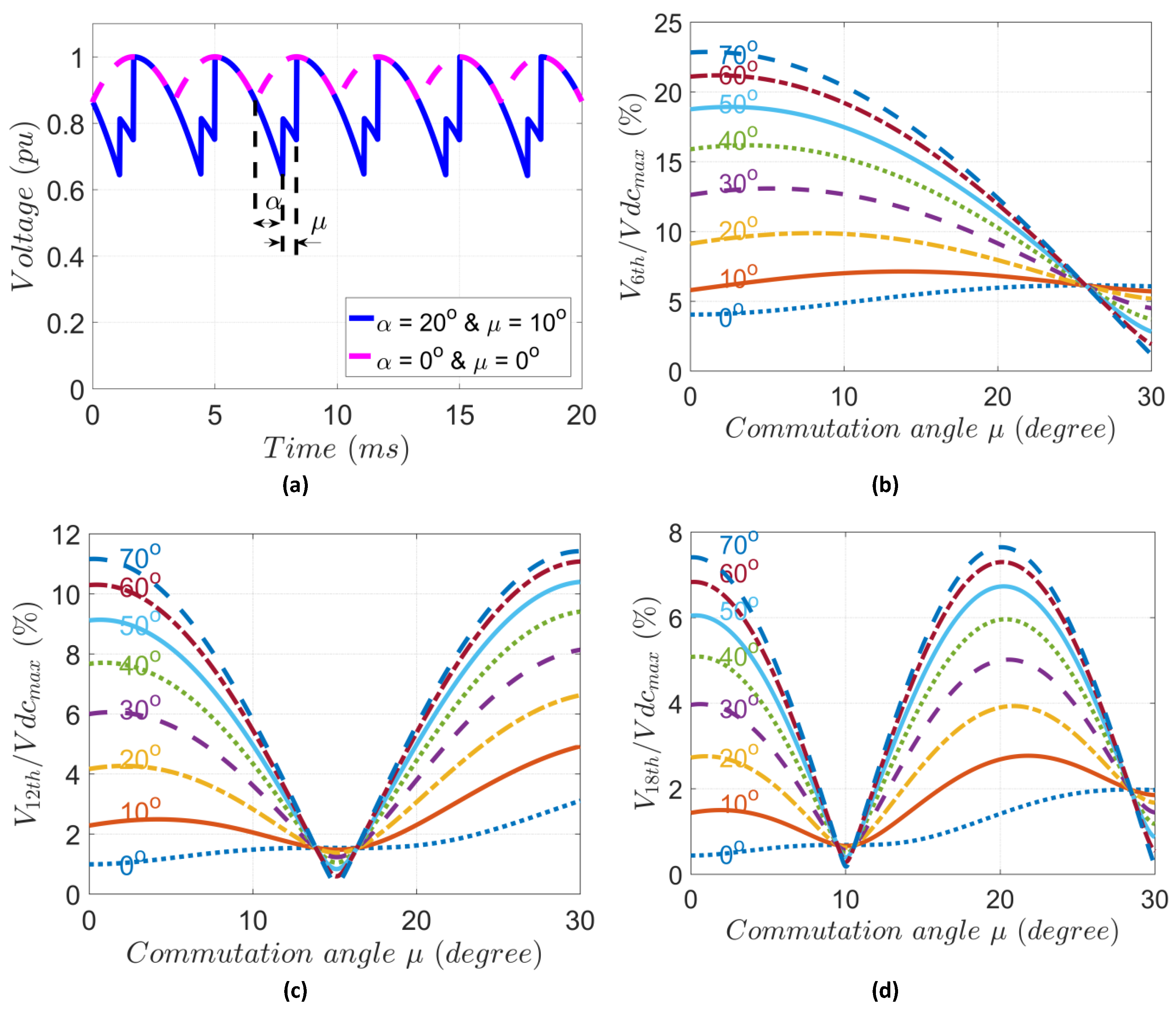
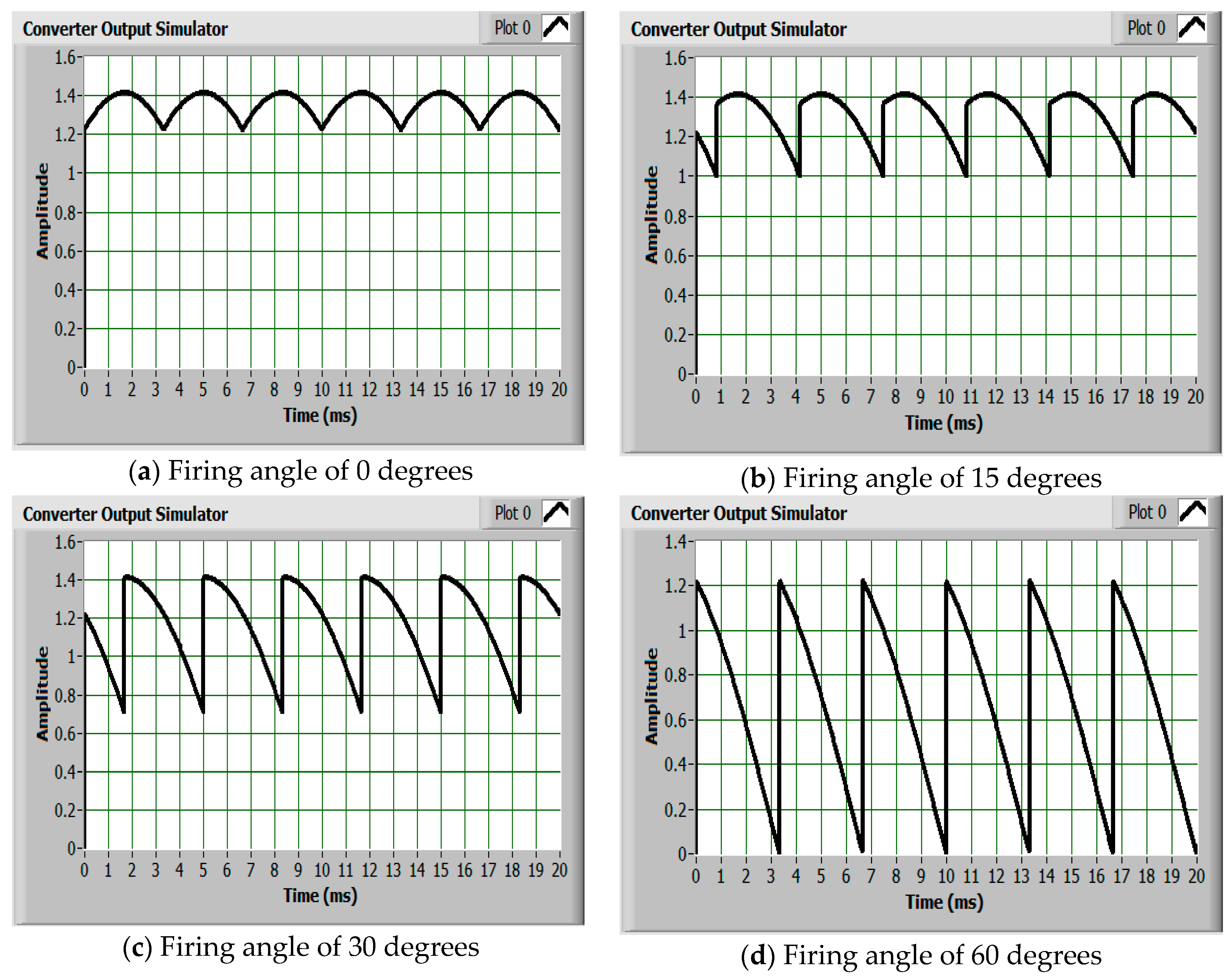
2. Superimposed Characteristic Harmonics

HVDC converters generate harmonics, due to their nonlinear operation, that appear as ripples in the DC side and in the form of distortions in the AC side of HVDC systems. The superimposed harmonic currents and voltages lead to power losses in transmission lines and would give rise to degradation of the insulation systems. Although the harmonic currents in the DC side contribute to ohmic losses in the cables, which can lead to temperature increase, their direct contribution to dielectric overstressing is less pronounced than that of harmonic voltages. This is due to the inductive nature of the DC side in LCC based HVDC systems [16].
In classic HVDC systems, a three-phase bridge rectifier [2] is the building block of the LCC converters, where the switching valves are based on thyristor technology, and they are turned on by gate firing circuitries and commutated by the AC line voltage alternation. Commonly, twelve-pulse converters are used in HVDC transmissions, where two six-pulse converters are connected in series and are fed by star and delta-connected transformers. The two constituent six-pulse converters may operate with symmetrical or asymmetrical firing angles (α) [17].
The firing angle is the main parameter that is used to control the direction and the amount of power to be exchanged between the two converter stations. Thus, it determines the level of harmonics, or ripples, introduced into the current and the voltage in the DC side. Typically, there is a minimum limit of 5° for the firing angle in LCC converters to ensure successful commutation of the switching valves, and, in addition, for normal operation of a rectifier, it lies within the range of 15° to 20°. However, when the converters start operation the firing angle is in the range of 60° to 70°; during the normal stopping the voltage is ramped down through the firing angle, and under some circumstances the firing angle is 9° [18]. The commutation angle μ is determined by the commutation impedance and its typical value is 20° during normal operation, but it is very small during disturbances [19].
In six-pulse converters, the harmonic voltages are multiples of 6, the number of distinct pulses the converter draws current from the AC system to perform the conversion [20]. A typical terminal voltage of a six-pulse converter along with its first three harmonic components (6th, 12th, and 18th) as a function of both firing and commutation angles illustrated in Figure 1.

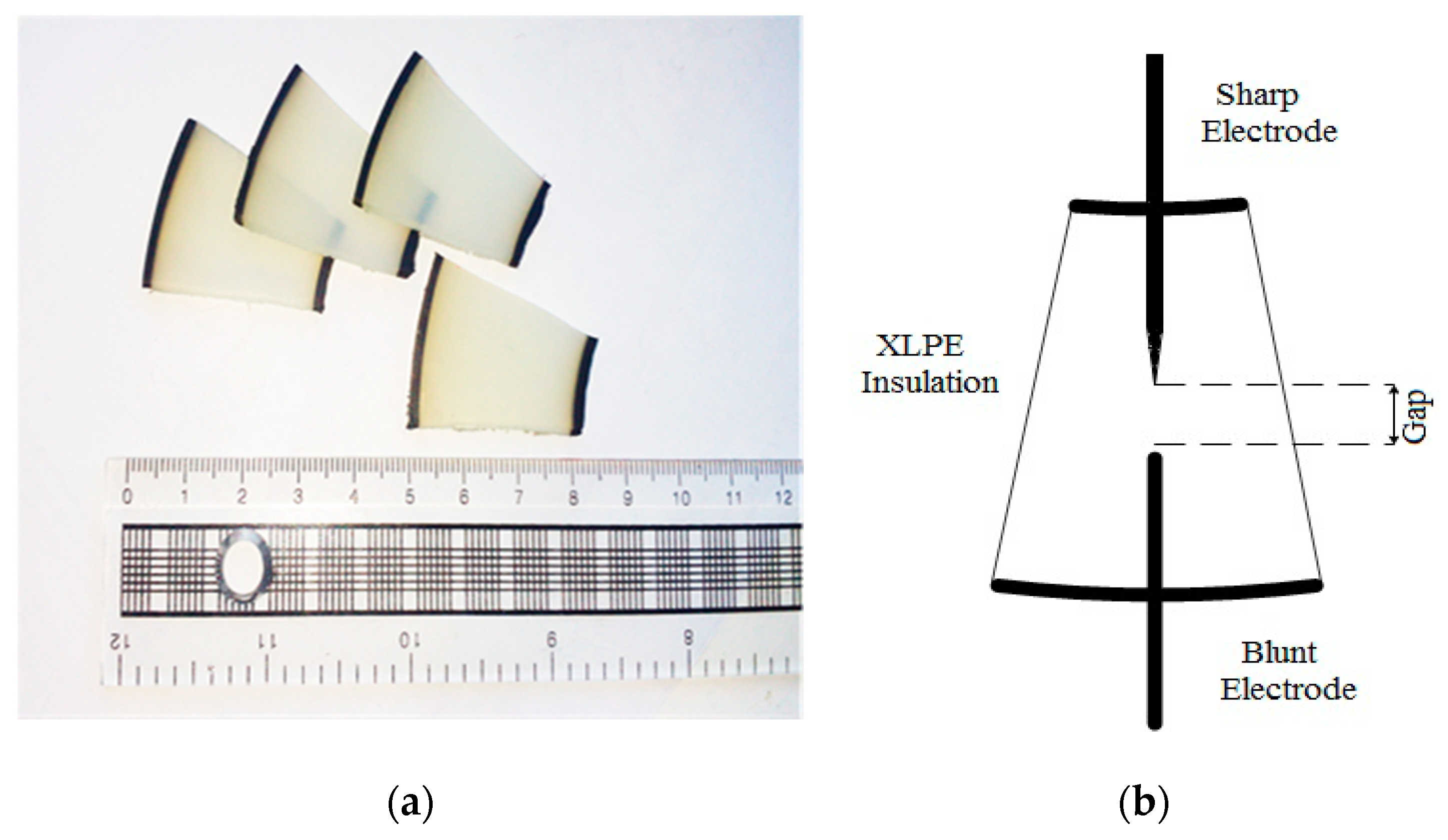
3. Sample Preparation

The samples were prepared from the insulation of a 400 kV DC cross-linked polyethylene cable. The merit of using HVDC cable insulation over the samples being used from AC cables or the samples being produced using molding methods in laboratories is to study the degradation of the insulating material which is specifically produced to be used in HVDC applications. The main insulation of the original cable had a circular cross section with internal radius of 65 mm and external radius 120 mm. As of the sample preparation procedure, first, the cable was cut into discs of 3 mm in thickness. Afterwards, the jacket of each disc was removed, and their cut-surfaces were finely polished using a grinding machine. This would allow a clearer optical observation of the treeing growth within the samples. The polished discs were then cut into sections as shown in Figure 2a.
In order to produce a non-uniform electric field—repressing, for example, a protruding defect—within the test sample, the double needle configuration (DNC) was adopted according to ASTM standard D3756-97 [21]. The electrode configuration comprises a sharp electrode with a tip radius of 5 µm and a blunt one with the shank of 0.9 mm. The electrodes were inserted into the bulk of the test samples from the curvature sides. To reduce the mechanical stresses applied to the samples, they were first uniformly heated at 65 °C [22] without causing any deformation, then the needles were carefully inserted into the samples, and the points of the needles were arranged to be 1 mm from each other as shown in Figure 2b. For a more detailed sample preparation procedure one can refer to reference [23].

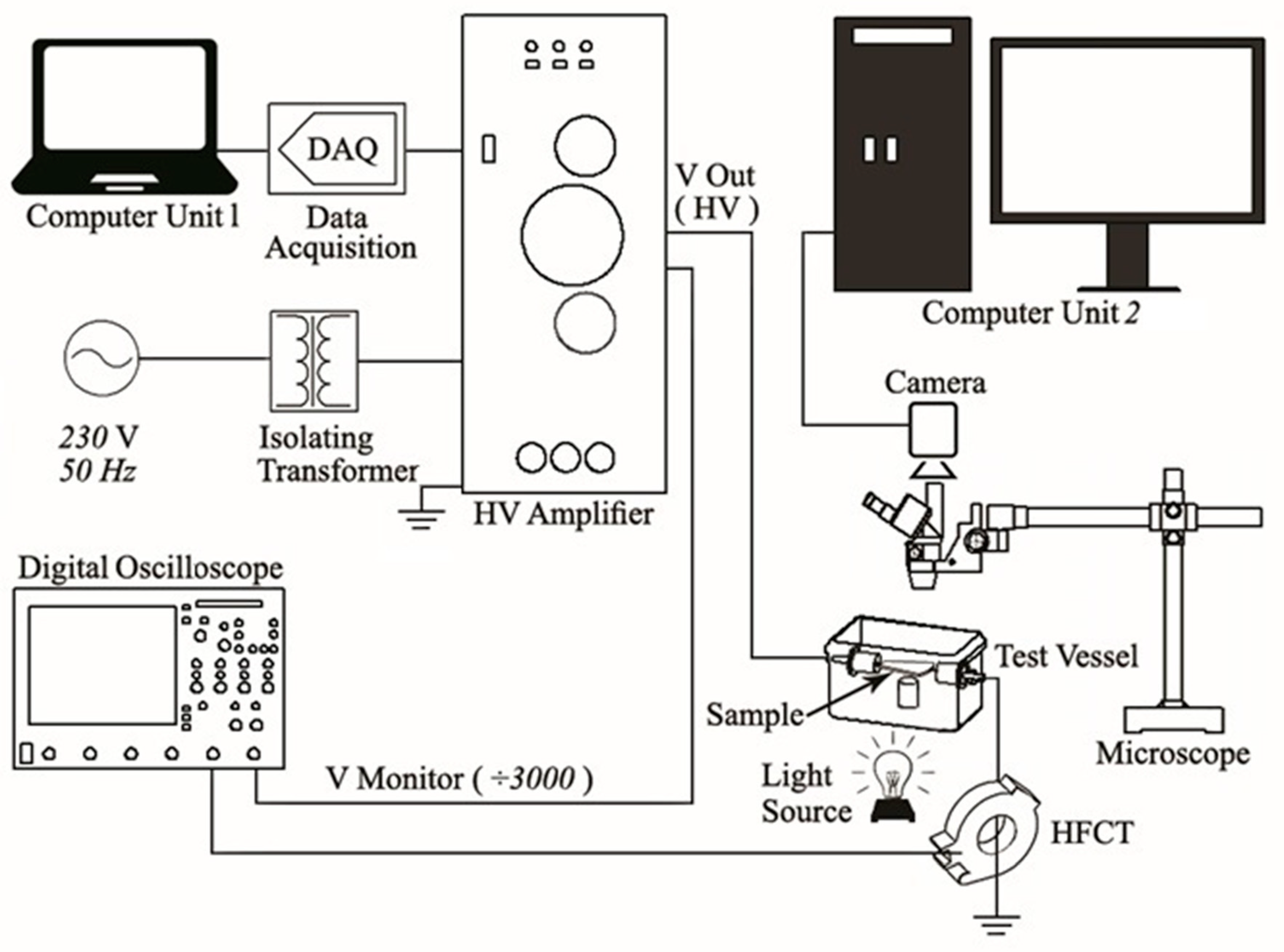
4. Experiment Setup and Test Procedure

The experimental setup is shown in Figure 3. It is composed of two main parts: the high voltage part, and the instrumentation part. In the high voltage, there is a high voltage amplifier with operational gain of 3 kV/V that replicates the original test signals in high voltage scales (±30 kV) [24], and the output terminal of the amplifier is connected to the test vessel, which holds the test sample. The sample was immersed in transformer oil within the test vessel to prevent possible corona discharges or flashover. Additionally, the oil helps augmenting the microscope’s resolution due to its high refractive index [25,26]. In order to detect the PD signals, an induction based sensor, known as High Frequency Current Transformer (HFCT), was appropriately clamped around the earth connection of the vessel. The sensor has a sensitivity of 4.3 mV/mA ± 5%, and it is capable of detecting PD signals within a wideband frequency range from around 0.2 MHz up to 19 MHz [23].
The instrumentation part comprised the test signal generating unit, PD measurement unit, and the optical monitoring unit to observe and record the electrical treeing within the samples. The original test signals were generated using an interlinked MATLAB (R2017b, MathWorks, Natick, MA, USA)-LabVIEW (R2015, National Instruments, Austin, TX, USA) environment running in computer Unit 1 and transmitted to the HV amplifier via a data acquisition card (DAQ). The PD recording unit is a digital oscilloscope (Lecroy) which was connected to the HFCT sensor via a coaxial cable to record the detected PD signals. The optical monitoring unit comprised a microscope and a camera. As illustrated, the objective lens of the optical microscope was in a suitable distance from the test vessel to provide suitable imaging. A digital camera of CMEX model was mounted on the microscope. The camera was then connected to computer Unit 2 via a shielded cable for recording the images of the treeing process. The sensitivity of the camera is 1.7 V/lux-sec, and it can produce images with a maximum resolution of 2592 × 1944 pixels [23].

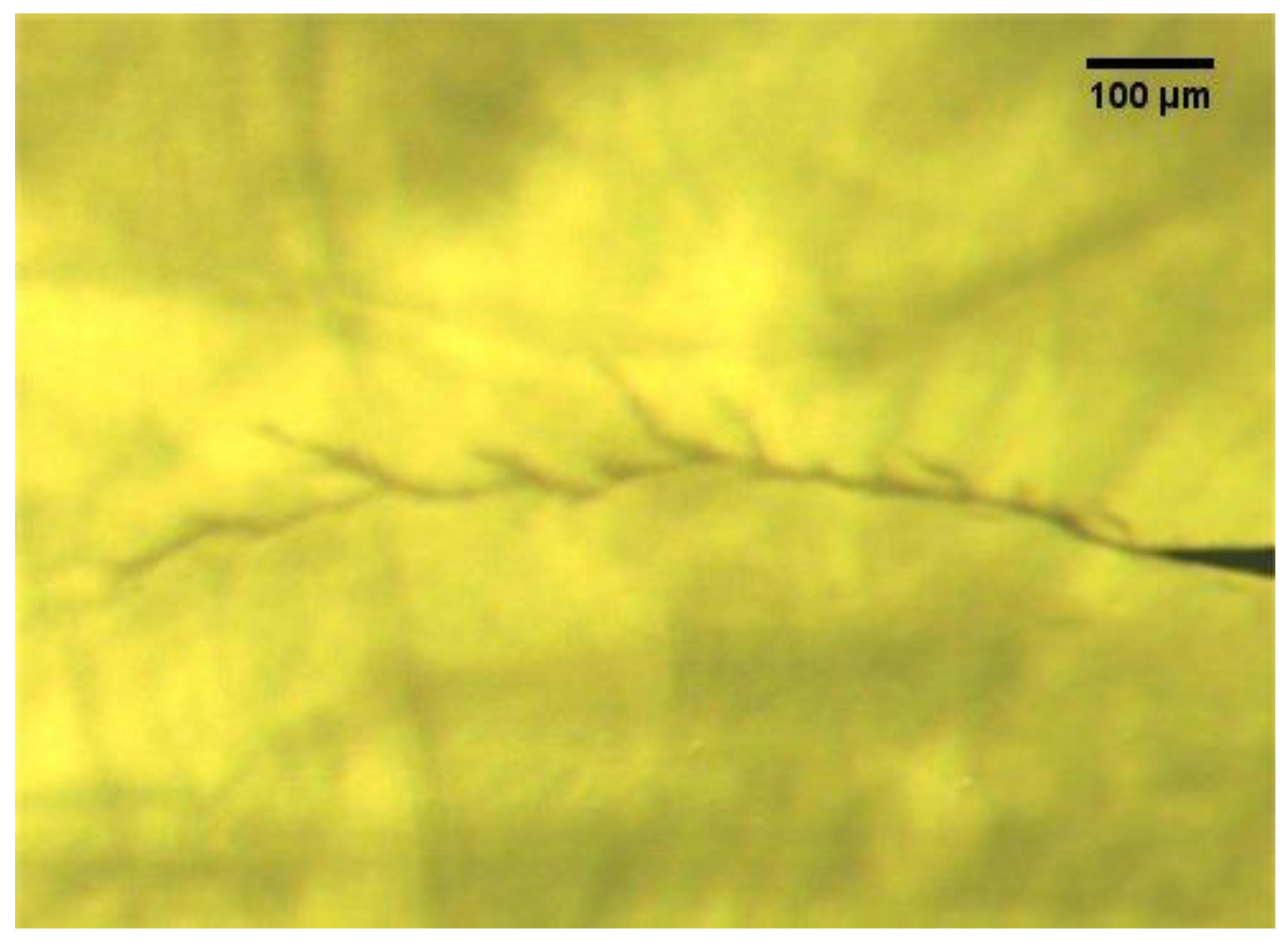
5. Experimental Results

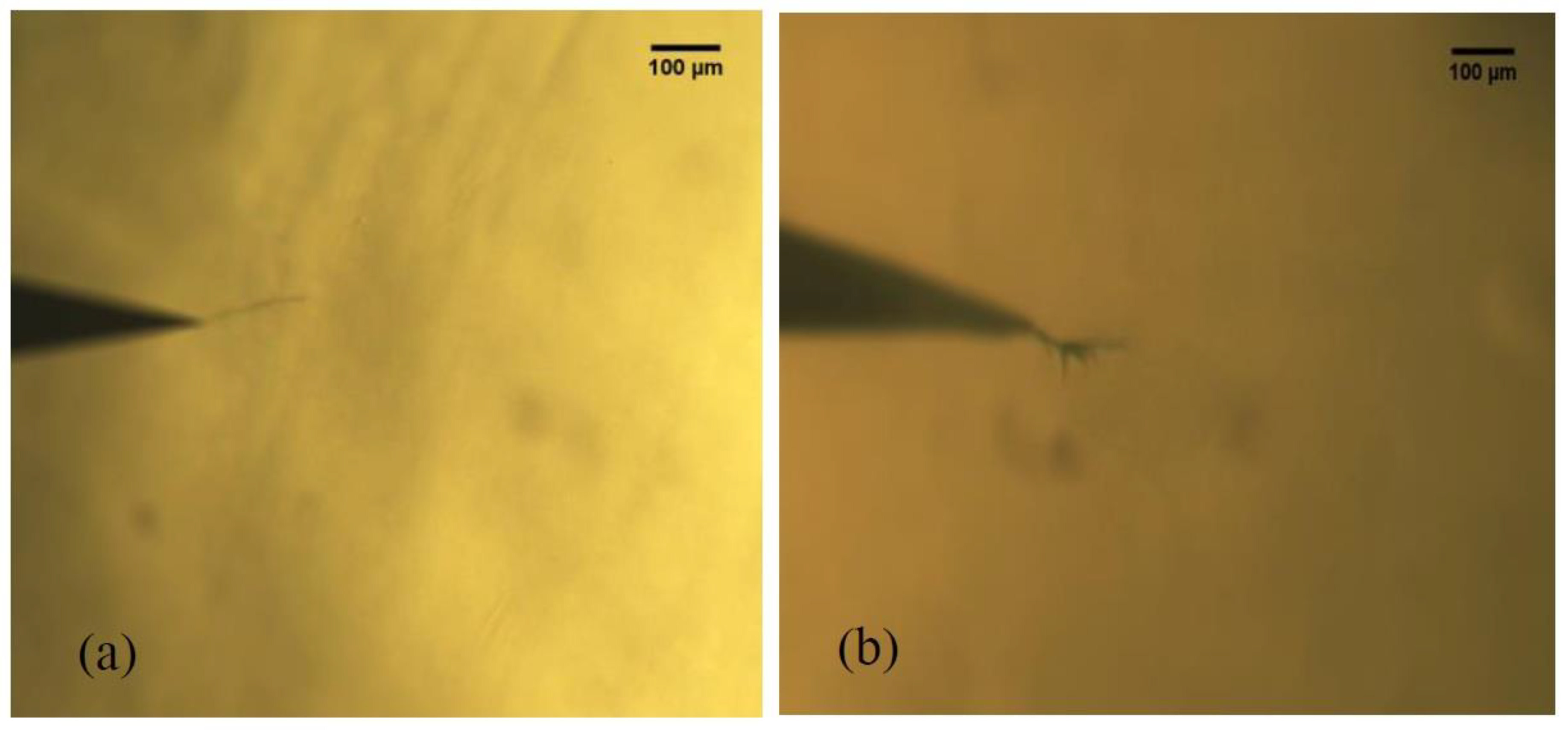
5.1. Electrical Treeing under Direct Current (DC) without Harmonic Voltage

The treeing process was studied under continuous application of direct current voltages with both positive and negative polarities separately, which can simulate the operational conditions of HVDC systems. The test voltage applied to the sample in a way that it was linearly increased from zero to the predefined level with a rate of 500 V/s. Throughout the test period, the development of treeing within the test samples was observed using the optical monitoring unit, and the emanated PD signals were measured by the electrical measurement unit, where a trigger level was set to reduce the influence of noise interferences. Three batches of samples, each comprised of ten samples, were tested at three different voltage levels. The first voltage magnitude was adopted based on the electric field being calculated using Equation (1), which has been proposed in Reference [20] for double electrode arrangements, and, furthermore, the treeing inception strength of XLPE material [27]. It is noteworthy that the calculated Laplacian field intensity is without considering space charge effect.
E max = 2 U r ln [ 2 d r ( 1 + 2 d R ) ]
where U is the potential difference across the needle electrodes, d is the gap distance between electrodes, and r and R are the respective radii of the sharp and the blunt needles. The second and third voltage levels were attained by increasing the first voltage with subsequent increment of 3 kV.
Table 1 gives the results of the electrical tree formations under positive and negative test voltages. It can be observed that there is no tree formation at the negative test voltages. However, development of trees was recorded at positive voltages. This suggests that the initiation of treeing depends not only on the strength of electric field but also on the polarity of the test voltage. A detailed discussion will be put forward in Section 5. The effect of non-continuous application of DC voltages on electrical treeing has been reported in [23] and Figure 4a,b illustrate the ET developments under the application of non-continuous positive and negative polarity voltages, respectively.

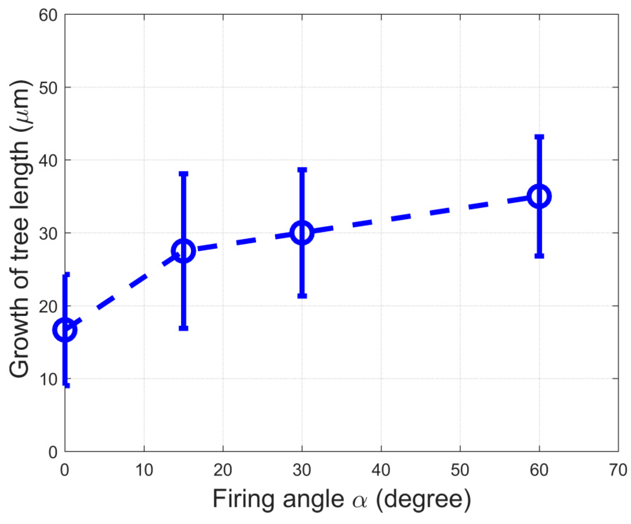
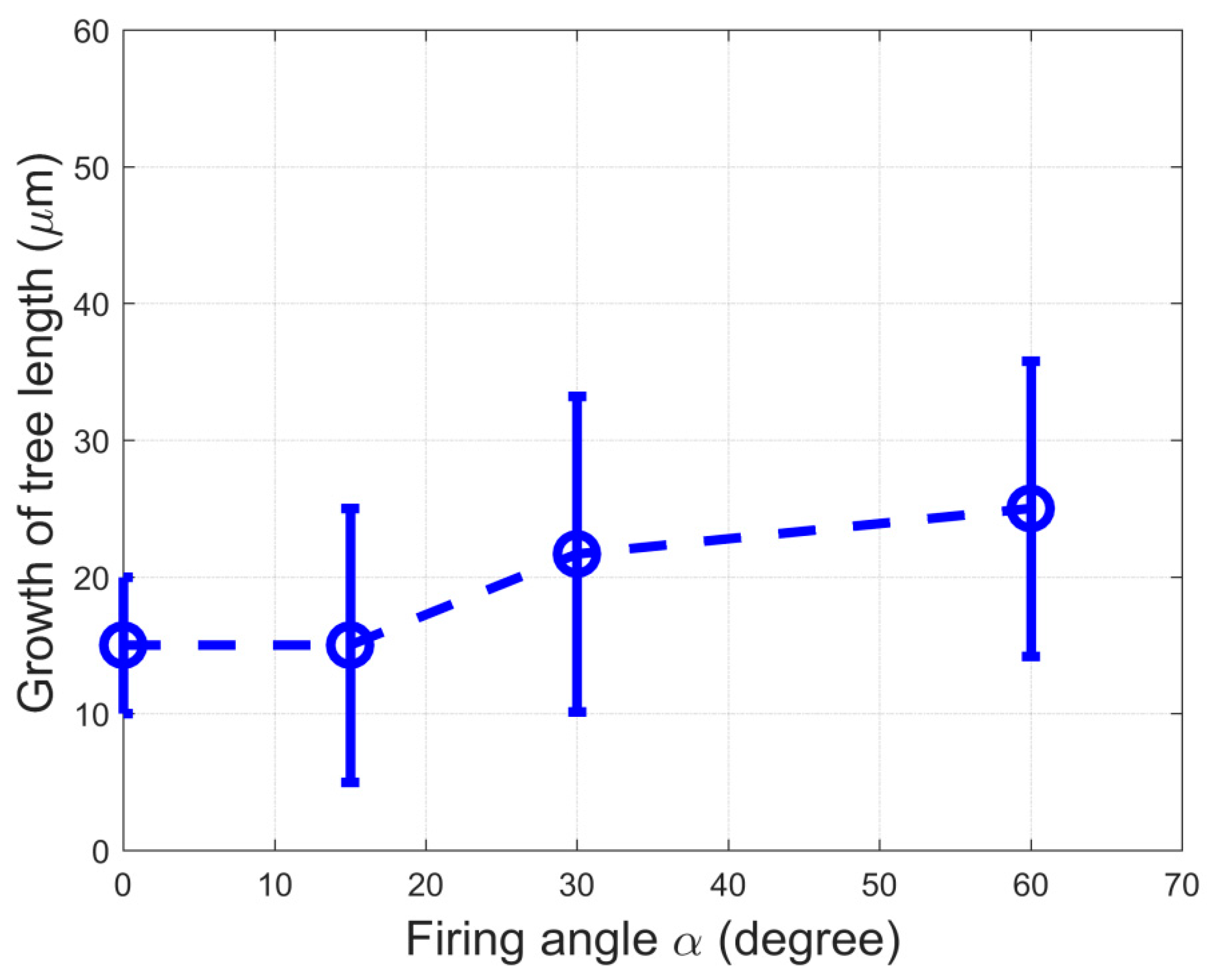
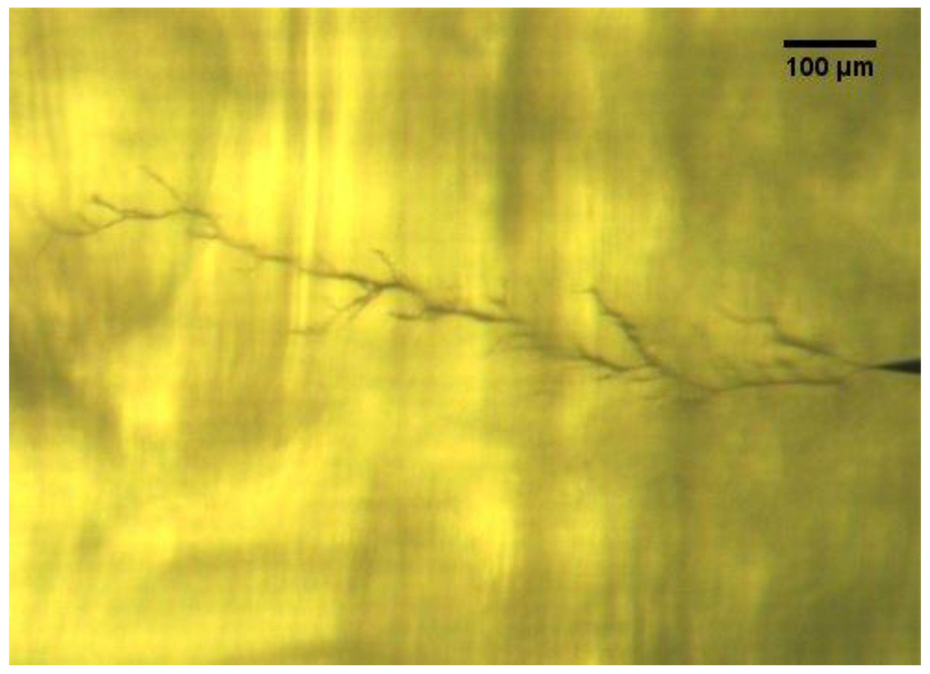
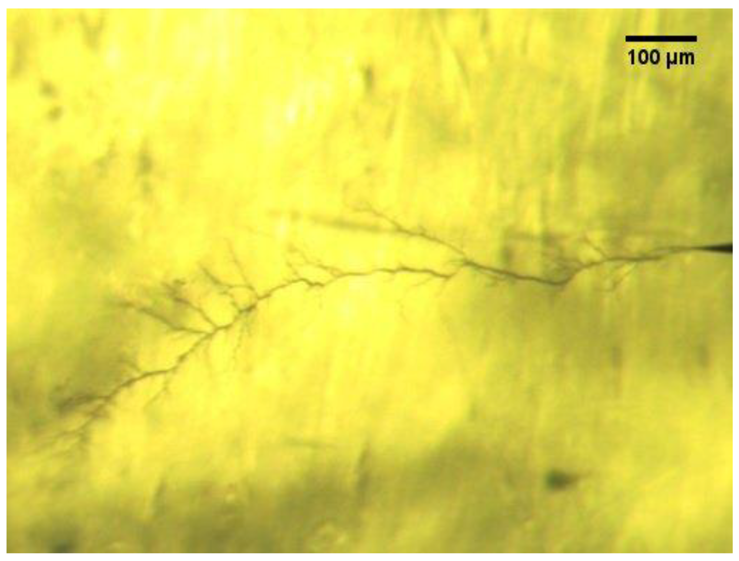
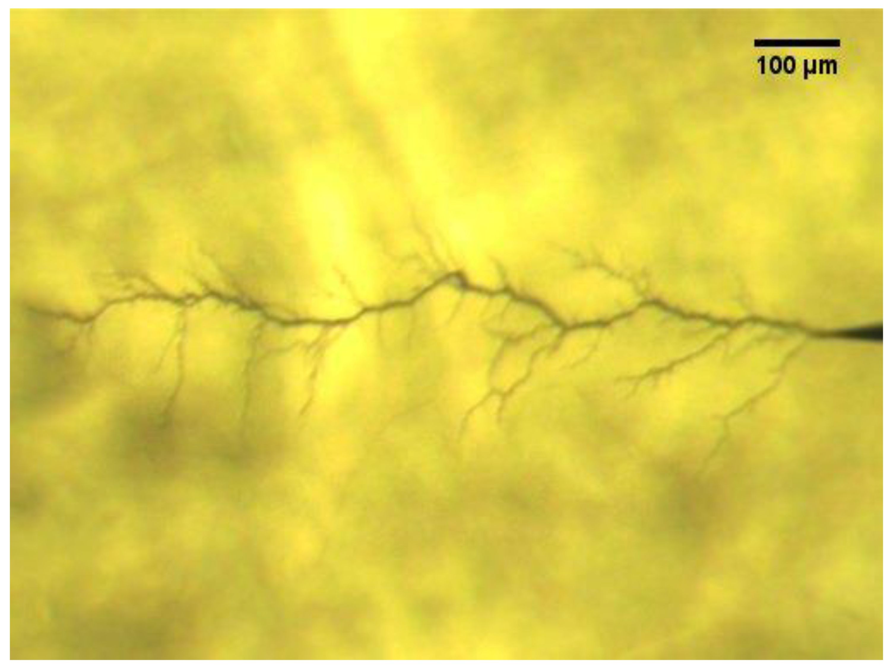
5.2. Electrical Tree under Direct Current (DC) with Harmonic Voltages

In order to study the effects of DC overlaid with harmonic voltages on the formation of electrical trees, two categories of positive and negative test voltages were considered. It is noteworthy to mention that the test voltages are unfiltered DC voltages. In other words, the voltages are without consideration of the effect of smoothing reactors. This would allow considering the worst case scenario of operation with harmonic contents that might happen due to malfunctioning of the DC side filter. Each category comprises four different voltage waveforms that were generated by varying the firing angle to 0°, 15°, 30°, and 60° using the six-pulse converter simulator. These waveshapes are shown in Figure 5a–d for positive voltages.
The samples were individually subjected to the test voltages and were monitored optically and electrically using the camera and the PD detection system, respectively. Table 2 shows the results of tree initiations within the samples for the four different test voltages at positive and negative polarities. There were no ET inceptions observed optically under the electric field of both positive and negative voltages for 0° and 15° firing delay angles. However, trees initiated at 30° and 60° firing angles at both polarities. The percentage of ET initiation is the same for the firing angle of 30° under both polarities. Nonetheless, as the firing delay angle increased to 60°, the number of test samples with ET initiation doubled compared to the case of 30° in positive polarity, but no increase was observed at negative polarity. This indicates that initiation of electrical treeing depends not only on the waveshape of the applied voltage, but the polarity of the electric field. This behavior of tree initiation could be due to the fact that under negative polarity voltages, the accumulated space charges reduce the electric field intensity at the tip of the needle, which leads to lowering the number of electrical tree inceptions compared to positive voltages [23].
Comparing the treeing results obtained for the ripple voltages with those obtained under the subjection of continuous pure DC voltages in Table 1, it can be observed that the frequency of ET formation under ripple voltages is higher than that of the continuous pure DC voltages. Under DC with ripple voltages (the superposition of DC and AC voltages) the electric field is of a fluctuating nature, which affects the dynamics of the space charge accumulation within the samples [28] and, hence, their distributions around the electrodes, which, altogether, can contribute to more tree ignitions at DC with ripple voltages.
Figure 6, Figure 7, Figure 8 and Figure 9 illustrate the ET growth for the four cases under the application of positive and negative voltages for firing delay angles of zero and sixty degrees respectively. Analysis of the results indicates that ET growth has a dependency on the waveshape and the polarity of the applied test voltages. As the fluctuation of the applied voltages elevates through increasing the firing delay angle, the complexity of the tree shape is augmented at both polarities; however, it is more pronounced under the negative polarity. Thusly, the physical structure of the trees and the visual property of the formed channels are being affected by the electric field at such voltages.
Generally, the trees that grew under negative polarity have a larger number of sprouts and fine branches compared to the tree structures that grew at positive voltages. Moreover, the ETs that developed under the lower firing angles, and lower levels of harmonics, tend to be of narrow structure; while at higher firing delay angles, which lead to sharper abruptions, the dimensions of trees are of wider structure and the number of minor branches are greater compared to the situation under lower firing delay angles. This indicates that the number of discharging sites increases at the subjection of negative voltage and there is higher activity of partial discharges.
Statistical analysis was conducted on the optically collected images of the developed trees under both polarities. Figure 10 and Figure 11 illustrate the treeing longitudinal growth against firing delay angle for positive and negative polarities, respectively. It can be observed that the average growth rate of ETs developed under the application of voltages of both polarities has an incremental trend as the firing angle increases. Furthermore, the values of growth rate reveal small differences under low firing delay angles; however, this difference is augmented as the firing delay increases. Visual inspection of the developed trees within the samples indicates that the waveshape and the polarity of the test voltages affect ET properties, which is an implication of destruction and abrasion level of the trees. The color of the tree channels and branches that were formed under lower ripples is lighter compared to that of those formed at voltages with higher ripples. Similarly, negative polarity voltages resulted in trees with channels of darker color, while the trees that have grown at positive voltages are of brownish color. This indicates that the tree channels that were developed under the subjection of negative polarity are more conductive due to carbonized tracking that PD activity leaves behind [29].

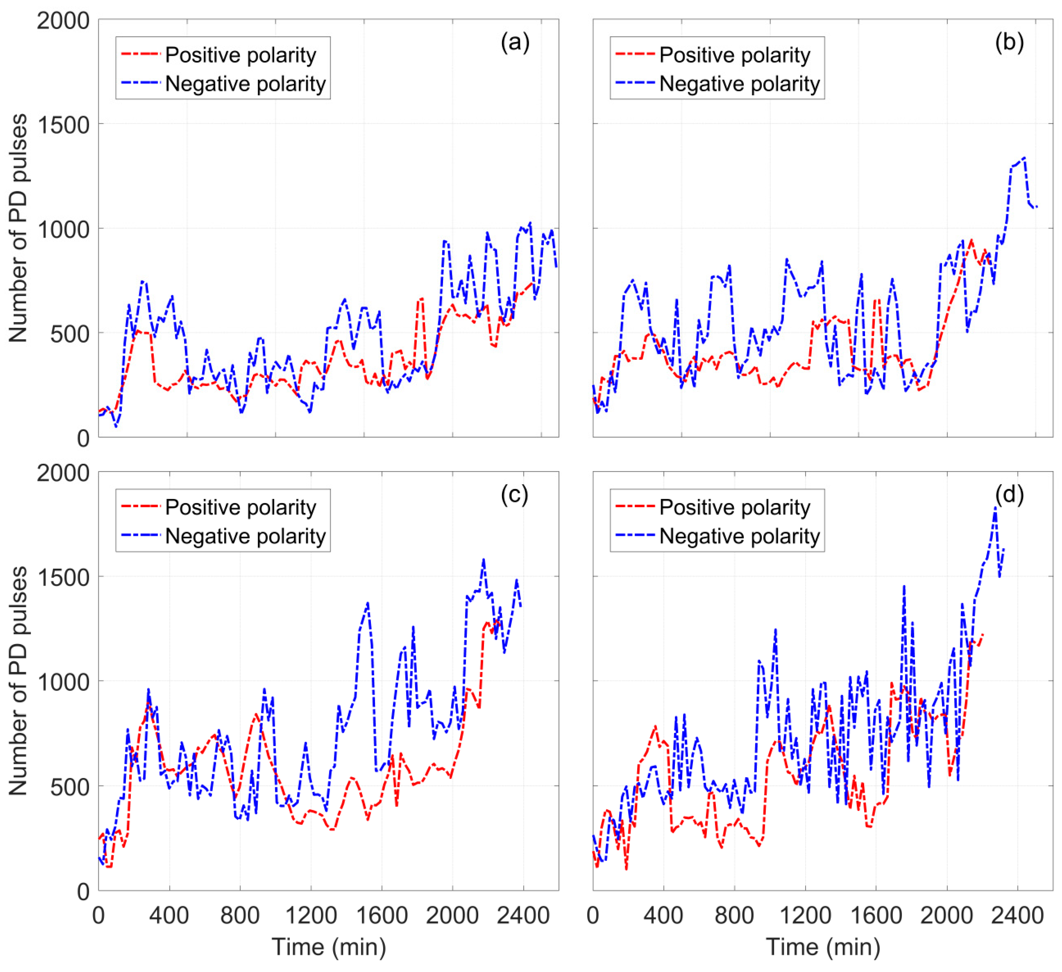
5.3. Partial Discharge (PD) Activities under Direct Current (DC) with Harmonic Voltages

Figure 12a–d illustrate the PD activities recorded during the growth of electrical trees within the samples under the subjection of positive and negative voltages for firing delay angles of 0° to 60°, respectively. Generally, all samples produce PD activities with a high dynamic behavior, where bursts, fluctuations, and stationary states can be observed. A low activity of PD pulses was observed at the early stage of the tree propagations. However, in the course of time this activity underwent a behavior comprising of various stages of pseudo-steady state and intermittent PD activities. The amount of PD pulses that occurred in all the samples shows an increasing trend in discharge recurrence, which is in correlation with the augmenting structure of the formed trees. The PD activity originating at negative polarity of applied voltages has shown some differences compared to those recorded under the positive voltages. Firstly, the average number of the partial discharges is higher in the former than the latter. Secondly, PD pulses occurring at negative polarity comprise dynamically sharp changes, which are particularly pronounced at higher firing delays. Thirdly, the time duration of PD activities at positive polarities is relatively short compared with the PD activities under negative polarity for the corresponding ET developments.

6. Discussion

In general, under the influence of unipolar electric fields, space charges accumulate in the vicinity of the sharp electrode and, depending on the magnitude and the polarity of the applied voltage, the amount of these charges varies [30]. At negative DC voltage, the homocharges that accumulate around the needle is of negative charge carriers. The depth that negative charge carriers can penetrate the insulation bulk is comparatively deeper than that of the positive charge carriers due to higher mobility of electrons [23]. The process of injection and extraction of highly energetic electrons into and from the regions where the electric field experiences fluctuations causes an accelerated deterioration of the insulation and can lead to formation of electrical trees.
Under the dynamical behavior of partial discharge activities, electrical trees exhibit a combination of steady and sudden changes. This might originate from the many factors and mechanisms that occur during the insulation degradation of the samples under ripple voltages. As a result of PDs that occur within the already formed channels or branches of a tree, the bulk of insulation deterioration results from the bombarded of highly energized electrons or ions; thusly, traces of graphite are left behind [31] which reduces PD activities within the carbonized channels. In addition, the gaseous byproducts being produced at the site of PDs contributes to increasing the gas pressure, which is also effective in the reduction of partial discharge activity. As the tree branches grow towards the opposing electrode, the intensity of the electric field increases at these locations, which leads to more discharges within the already formed micro-cavities. Furthermore, the overnight pauses that were introduced to the voltage application as a result of the test procedure, could also influence the fluctuation in PD activity, which provides enough time for the recovery of the insulation and redistribution of the already built up space charges. These phenomena in synergy with the environmental factors contribute to the dynamical PD activity during ET formation within the test samples. The physical structures of the trees that formed under DC waveforms were all categorized as branch type according to the definition given in Reference [5] while formation of various types of electrical trees such as bush, branch, and bush–branch have been reported in the literature for AC voltages [32,33]. Furthermore, in all the test samples, the trees initiated from the high voltage electrode and propagated towards the ground electrode, with no observable reverse trees detected. These features could signify another difference underlaying the mechanism of treeing phenomenon at AC and DC voltages.

7. Conclusions

The influence of DC voltages superimposed with characteristic harmonics on PD activity and ET developments within DC XLPE dielectric test samples were studied experimentally. Generally, the structure of the developed electrical trees and the activity of the associated partial discharges depend upon the waveshape and harmonic contents of the applied test voltages and the polarity of the voltages. The possibility of electrical tree inception is higher in the case of DC voltage with ripple, owing to the synergic effect of the accumulated space charges and the electric field exposed by the external voltage source compared to the conditions under pure DC voltages. This indicates that insulation degradation is a field-dynamics dependent phenomenon, i.e. ET and PD activities undergo dynamic changes in the regions of insulation anomalies where intensified stress is produced by the added harmonic voltages.
Partial discharges and electrical trees are among the major insulation degrading phenomena that can lead to power cable breakdown. Therefore, understating of such deteriorating mechanisms under deemed operational conditions of HVDC systems would help to adopt effective insulation condition monitoring and diagnostic techniques. This can help the network owner and operator to perform more effective asset management to reduce unscheduled downtime, hence, increase the availability and the reliability of the power systems; the research will also benefit manufacturers of HVDC cable in terms of understanding the properties and mechanisms of ETs in these systems, and design improvements.

Author Contributions

Methodology, M.A.F., M.E.F., and A.R.; Investigation, M.A.F.; Writing-Original Draft Preparation, M.A.F.; Writing-Review & Editing, all the authors.

Funding

This research received no external funding.

Conflicts of Interest

The authors declare no conflict of interest.

References

  1. Van Hertem, D.; Gomis-Bellmunt, O.; Liang, J. HVDC Grids: For Offshore and Supergrid of the Future, 1st ed.; John Wiley Sons Inc.: Hoboken, NJ, USA, 2016; ISBN 978-1-118-85915-5. [Google Scholar]
  2. Arrillaga, J. High Voltage Direct Current Transmission, 1st ed.; Institute of Electrical Engineering: London, UK, 1998; ISBN 13: 9780852969410. [Google Scholar]
  3. Fabiani, D.; Montanari, G. The Effect of Voltage Distortion on Ageing Acceleration of Insulation Systems under Partial Discharge Activity. IEEE Trans. Dielectr. Electr. Insul. 2001, 17, 24–33. [Google Scholar] [CrossRef]
  4. Liu, T.; Lv, Z.; Wang, Y.; Wu, K.; Dissado, L.; Peng, Z.; Li, R. A new method of estimating the inverse power law ageing parameter of XLPE based on step-stress tests. In Proceedings of the 2013 Annual Report Conference on Electrical Insulation and Dielectric Phenomena, Shenzhen, China, 20–23 Februery 2013; pp. 69–72. [Google Scholar]
  5. Dissado, L.A.; Fothergill, J.C. Electrical Degradation and Breakdown in Polymers, 1st ed.; Peter Peregrinus Ltd.: London, UK, 1992; ISBN 0863411967. [Google Scholar]
  6. Bozzo, R.; Gemme, C.; Guastavino, F.; Montanari, G.C. Investigation of aging rate in polymer films subjected to surface discharges under distorted voltage. In Proceedings of the IEEE 1997 Annual Report Conference on Electrical Insulation and Dielectric Phenomena, Minneapolis, MN, USA, 19–22 October 1997; Volume 2, pp. 435–438. [Google Scholar]
  7. Bahadoorsingh, S.; Rowland, S.M. Modeling of partial discharges in the presence of harmonics. In Proceedings of the 2009 IEEE Conference on Electrical Insulation and Dielectric Phenomena, Virginia Beach, VA, USA, 18–21 October 2009; pp. 384–387. [Google Scholar]
  8. Bodega, R.; Cavallini, A.; Morshuis, P.H.F.; Wester, F.J. The effect of voltage frequency on partial discharge activity. In Proceedings of the Annual Report Conference on Electrical Insulation and Dielectric Phenomena, Cancun, Mexico, 20–24 October 2002; pp. 685–689. [Google Scholar]
  9. Florkowski, M.; Florkowska, B.; Furga, J.; Zydron, P. Impact of high voltage harmonics on interpretation of partial discharge patterns. IEEE Trans. Dielectr. Electr. Insul. 2013, 20, 2009–2016. [Google Scholar] [CrossRef]
  10. Bahadoorsingh, S.; Rowland, S. Investigating the Impact of Harmonics on the Breakdown of Epoxy Resin through Electrical Tree Growth. IEEE Trans. Dielectr. Electr. Insul. 2010, 17, 1576–1584. [Google Scholar] [CrossRef]
  11. Xie, A.; Zheng, X.; Li, S.; Chen, G. Investigations of Electrical Trees in the Inner Layer of XLPE Cable Insulation Using Computer-Aided Image Recording Monitoring. IEEE Trans. Dielectr. Electr. Insul. 2010, 17, 685–693. [Google Scholar] [CrossRef]
  12. Sarathi, R.; Nandini, A.; Tanaka, T. Understanding electrical treeing phenomena in XLPE cable insulation under harmonic ac voltages adopting uhf technique. IEEE Trans. Dielectr. Electr. Insul. 2012, 19, 903–909. [Google Scholar] [CrossRef]
  13. Olsen, P.; Mauseth, F.; Ildstad, E. The Effect of DC Superimposed AC Voltage on Partial Discharges in Dielectric Bounded Cavities. In Proceedings of the International Conference on High Voltage Engineering and Application (ICHVE), Poznan, Poland, 8–11 September 2014; pp. 1–4. [Google Scholar]
  14. Klueter, T.; Wulff, J.; Jenau, F. Measurement and statistical analysis of partial discharges at DC voltage. In Proceedings of the 2013 48th International Universities’ Power Engineering Conference (UPEC), Dublin, Ireland, 2–5 September 2013; pp. 1–5. [Google Scholar]
  15. Cavallini, A.; Montanari, G.C.; Tozzi, M.; Chen, X. Diagnostic of HVDC systems using partial discharges. IEEE Trans. Dielectr. Electr. Insul. 2011, 18, 275–284. [Google Scholar] [CrossRef]
  16. British Standards Institution. IEC60270, High Voltage Test Techniques—Partial Discharge Measurements, 1st ed.; British Standards Institution: London, UK, 2000. [Google Scholar]
  17. Hamad, M.S.; Masoud, M.I.; Williams, B.W. Medium-voltage 12-pulse converter: Output voltage harmonic compensation using a series APF. IEEE Trans. Ind. Electron. 2014, 61, 43–52. [Google Scholar] [CrossRef]
  18. Kundur, P. Power System Stability and Control, 1st ed.; McGraw Hill: New York, NY, USA, 1994. [Google Scholar]
  19. Mircea, A.; Philip, M. HVDC Submarine Power Cables in the World. EUR 27527 EN, 1st ed.; Publications Office of the European Union: Luxembourg, 2015. [Google Scholar]
  20. Arrillaga, J.; Watson, N.R. Power System Harmonics, 2nd ed.; Wiley: Hoboken, NJ, USA, 2003. [Google Scholar]
  21. ASTM International. Standard Test Method for Evaluation of Resistance to Electrical Breakdown by Treeing in Solid Dielectric Materials Using Diverging Fields; ASTM D3756-97; ASTM International: West Conshohocken, PA, USA, 2010. [Google Scholar]
  22. Qi, X.; Boggs, S. Thermal and mechanical properties of EPR and XLPE cable compounds. IEEE Electr. Insul. Mag. 2006, 22, 19–24. [Google Scholar] [CrossRef]
  23. Fard, M.; Farrag, M.; McMeekin, S.; Reid, A. Electrical Treeing in Cable Insulation under Different HVDC Operational Conditions. Energies 2018, 11, 2406. [Google Scholar] [CrossRef]
  24. Azizian Fard, M.; Reid, A.J.; Hepburn, D.M.; Farrag, M.E. Partial discharge behavior under HVDC superimposed with transients. In Proceedings of the 51st International Universities Power Engineering Conference (UPEC), Coimbra, Portugal, 6–9 September 2016; pp. 1–5. [Google Scholar]
  25. Abramowitz, M.; Davidson, M.W. Microscope Objectives: Immersion Media. Olympus Microscopy Resource Center. Available online: http://www.olympusmicro.com/primer/anatomy/immersion.html (accessed on 10 January 2017).
  26. Babadi, S.; Ramirez-Iniguez, R.; Boutaleb, T.; Mallick, T. Performance comparison of a freeform lens and a CDTIRO when combined with an LED. IEEE Photonics J. 2017, 9, 1–8. [Google Scholar] [CrossRef]
  27. McMahon, E.J. A tutorial on treeing. IEEE Trans. Electr. Insul. 1978, 13, 277–288. [Google Scholar] [CrossRef]
  28. Ziyu, L.; Rongsheng, L.; Huiming, W.; Wenbin, L. Space charges and initiation of electrical trees. IEEE Trans. Electr. Insul. 1989, 24, 83–89. [Google Scholar] [CrossRef]
  29. Minoda, A.; Nagao, M.; Kosaki, M. Dc short-circuit treeing phenomenon and space charge effect in epr at cryogenic temperature. In Proceedings of the 5th International Conference on Properties and Applications of Dielectric Materials, Seoul, South Korea, 25–30 May 1997; Volume 1, pp. 426–429. [Google Scholar]
  30. Marzzanti, G.; Marzinotto, M. Extruded Cables for High Voltage Direct Current Transmission: Advance in Research and Development; Wiley-IEEE Press: Hoboken, NJ, USA, 2013; ISBN 978-1-118-09666-6. [Google Scholar]
  31. Mammeri, M.; Laurent, C.; Nedjar, M. Dynamics of voltage polarity reversal as the controlling factor in space-charge induced breakdown of insulating polymers. IEEE Trans. Dielectr. Electr. Insul. 1997, 4, 44–51. [Google Scholar] [CrossRef]
  32. Densley, R.J. An investigation into the growth of electrical trees in xlpe cable insulation. IEEE Trans. Electr. Insul. 1979, EI-14, 148–158. [Google Scholar] [CrossRef]
  33. Dissado, L.A.; Dodd, S.J.; Champion, J.V.; Williams, P.I.; Alison, J.M. Propagation of electrical tree structures in solid polymeric insulation. IEEE Trans. Dielectr. Electr. Insul. 1997, 4, 259–279. [Google Scholar] [CrossRef]
Figure 1. (a) Terminal voltage; (b) Sixth harmonic; (c) Twelfth harmonic; and (d) Eighteenth harmonic.
Energies 12 03113 g001
Figure 2. Test sample preparation: (a) samples; and (b) final test sample with electrodes.
Energies 12 03113 g002
Figure 3. Experimental setup for electrical treeing (ET) optical observation and partial discharge (PD) measurement.
Energies 12 03113 g003
Figure 4. Development of electrical treeing (ETs) at direct current (DC) voltage (a) +28 kV and (b) −28 kV [23].
Energies 12 03113 g004
Figure 5. Output voltages of the converter simulator for firing angles of (a) 0°, (b) 15°, (c) 30°, and (d) 60°.
Energies 12 03113 g005
Figure 6. Electrical tree developed at positive voltage with firing angle of 0 degrees.
Energies 12 03113 g006
Figure 7. Electrical tree developed at negative voltage with firing angle of 0 degrees.
Energies 12 03113 g007
Figure 8. Electrical tree developed at positive voltage with firing angle of 60 degrees.
Energies 12 03113 g008
Figure 9. Electrical tree developed at negative voltage with firing angle of 60 degrees.
Energies 12 03113 g009
Figure 10. Growth of tree length against the firing delay angle at positive voltage.
Energies 12 03113 g010
Figure 11. Growth of tree length against the firing delay angle at negative voltage.
Energies 12 03113 g011
Figure 12. Partial discharge (PD) activities associated with electrical trees at positive and negative voltage magnitude of 28 kV with firing delay angles of (a) 0, (b) 15, (c) 30, and (d) 60 degrees.
Energies 12 03113 g012
Table 1. Tree inception at continuous pure direct current (DC) voltages.
Voltage Level (kV)Positive DCNegative DC
Percentage of Samples in Which ET’s Initiated (%)Percentage of Samples in Which ET’s Initiated (%)
22.000
25.0200
28.0200
Table 2. Tree initiation at direct current (DC) with ripple voltages.
Firing Angle (α) in Degrees Positive DCNegative DC
Percentage of Samples in Which ET’s Initiated (%)Percentage of Samples in Which ET’s Initiated (%)
000
1500
302020
604020

