CALAJOULE: An Italian Research to Lessen Joule Power Losses in Overhead Lines by Means of Innovative Conductors

 ,
, 
 ,
,  , ,
, ,
Abstract
1. Introduction
2. Current Solutions for Overhead Lines Conductors
2.1. State-of-the-Art of OHL Conductors
2.2. Existing Conductors for Transmission OHLs
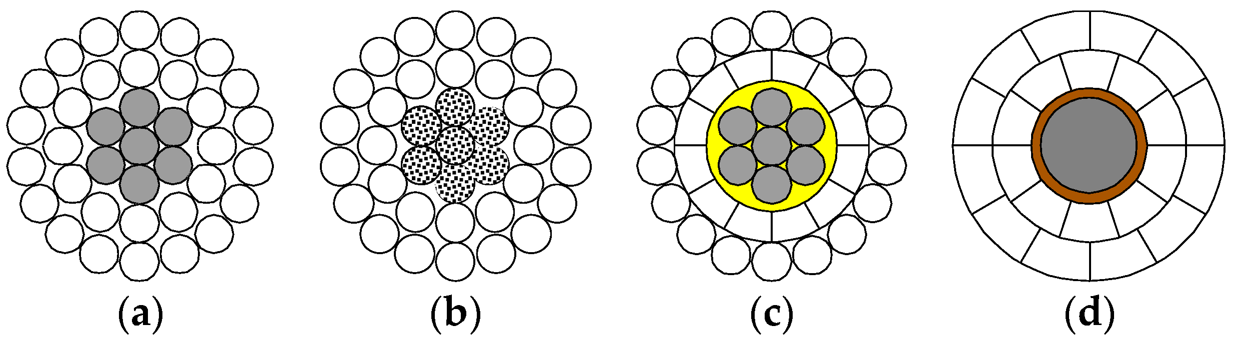
- Aluminium Conductor Steel Reinforced, ACSR, or Aluminium Conductor Steel Supported, ACSS, composed by annealed aluminium strands (or even trapezoidal wires, in the ACSS case) over a stranded steel core: this is the most commonly adopted solution for transmission OHLs;
- Aluminium Conductor Composite Reinforced, ACCR, typically composed by a high-temperature aluminium alloy over a composite core of aluminium fibers embedded in a pure aluminium matrix. The same structure is also used in (Z)TACIR conductors, in which the core is in INVAR (steel and nickel alloy with very low linear expansion coefficient);
- Gap-type Aluminium Conductor Steel Reinforced, G(Z)TACSR, consisting of an external thermal-resistant aluminium alloy (with a layer of trapezoidal wires), separated from the steel core by a gap filled with grease to allow the two layers to move independently. This ensures to apply the mechanical tension on the steel core only while increasing the aluminium cross-section for a reduced electrical resistance;
- Aluminium Conductor Composite Core, ACCC/TW, typically made of trapezoidal wires of thermal-resistant aluminium alloy over a core consisting of carbon fibers (in the inner part) surrounded by a coating of glass fibers. This configuration gathers the advantage of increased aluminium cross-section and weight lowering due to the use of a carbon fiber core.
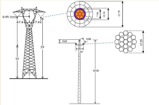
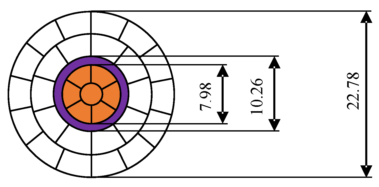
3. Innovative Conductor for Transmission OHLs
3.1. Conductor Characteristics
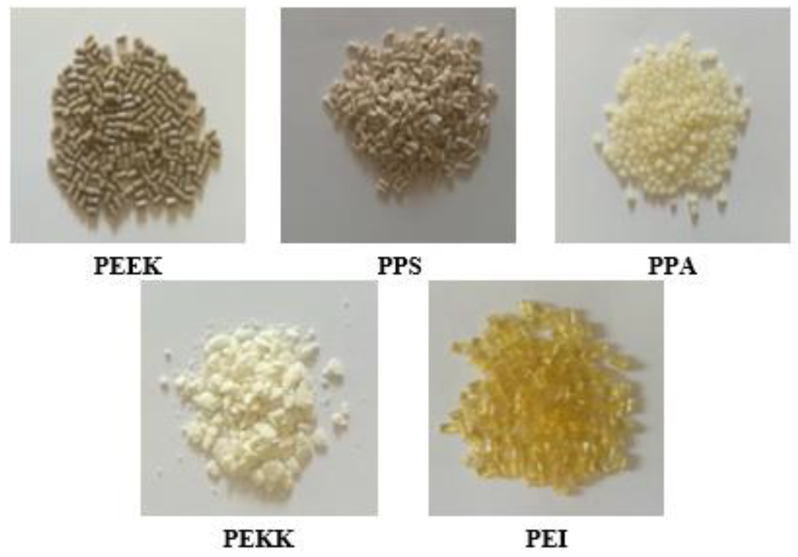
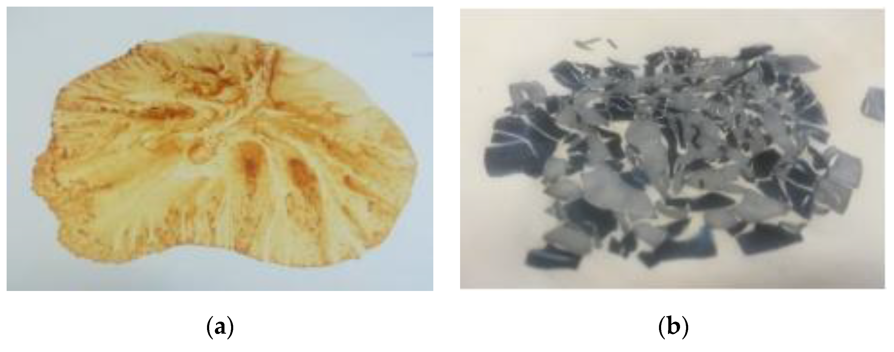
3.2. Experimental Research on Core-Coating Materials
- PEEK, polyetheretherketone, is a semicrystalline thermoplastic technopolymer that can be used at high temperatures. It has high mechanical and chemical resistance, is resistant to abrasion, is not flammable, resists to high energy radiation.
- PEKK, polyetherketoneketone, is a semicrystalline thermoplastic polymer with high heat resistance, significant mechanical strength and rigidity, combined with good chemical resistance. It is an intrinsically fireproof material with limited smoke generation and low toxicity in case of fire.
- PEI, polyetherimide, is an amorphous technopolymer that can be used continuously at high temperatures. Its properties also include high mechanical strength and rigidity even at high temperatures, dimensional stability for low moisture absorption, and good electrical properties. It is inherently flame retardant and chemically resistant and its electrical properties are stable even under varying temperature, humidity and frequency conditions.
- PPA, polyphthalamide, is a semicrystalline aromatic polyamide. Compared to polyamide 6.6 it is more mechanically resistant, more rigid, less sensitive to moisture, and has improved thermal properties, fatigue, and creep resistance factors that make it applicable in a wide range of sectors;
- PPS, polyphenylene sulfide, is a semicrystalline polymer with excellent thermal resistance. This material is characterized by inherent low flammability and good chemical resistance. It has very low moisture absorption, high mechanical strength, and dimensional stability.
3.3. Clamping Equipment for the Proposed ACCM/TW Conductor
- having an electrical conductivity at least equal to that of the conductor with a negligible contact resistance (to reduce heating of the terminal) and
- avoiding corrosion due to electrolytic torques deriving from contact between metals of different types.
4. Innovative Conductor for Distribution OHLs
5. Assessment of Benefits from the Installation of Innovative Conductors
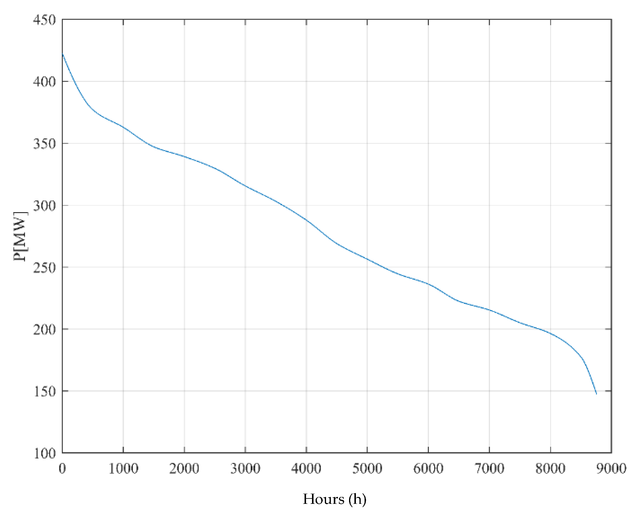
5.1. Benefit Assessment Methodology
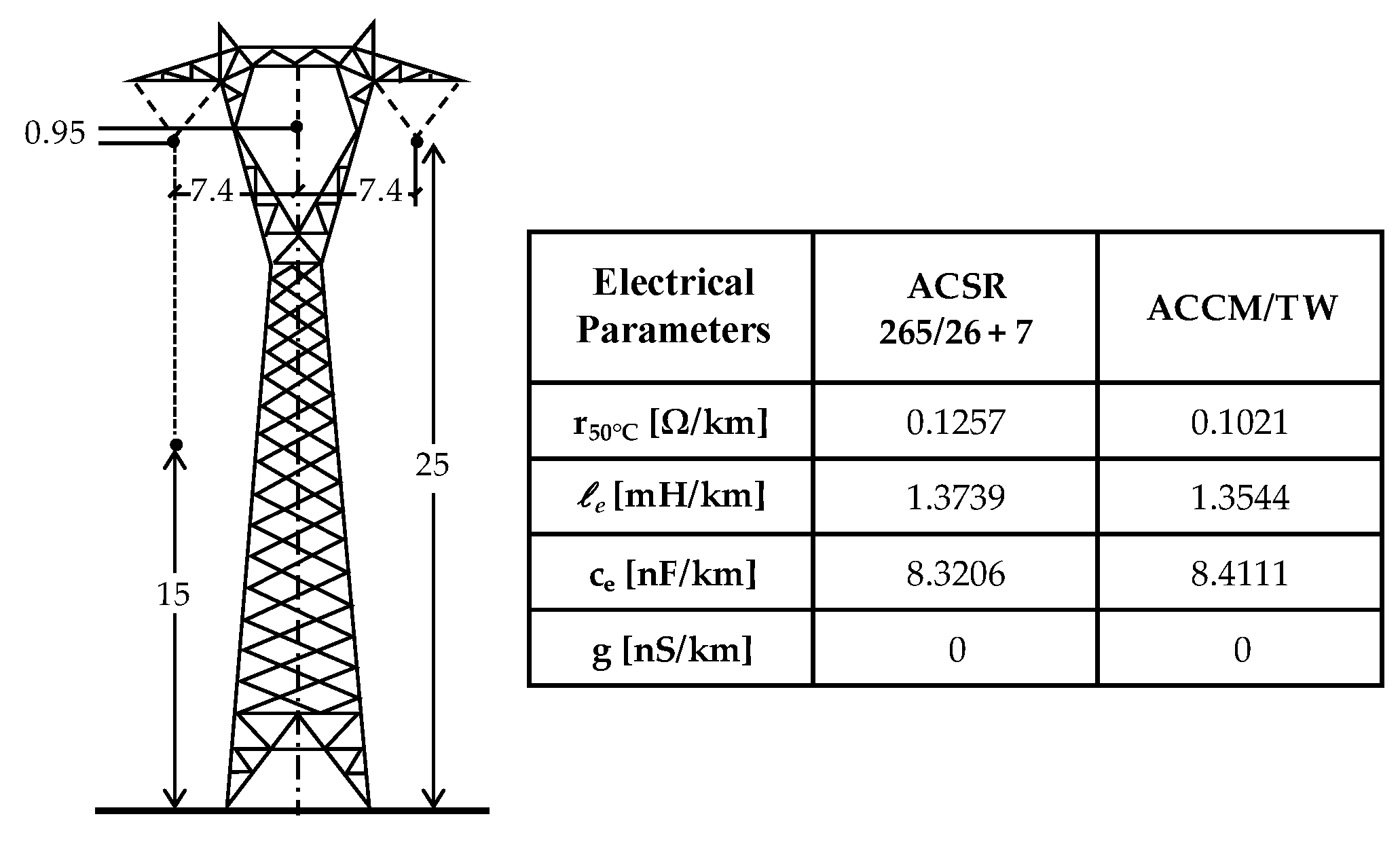
5.2. Transmission Grid OHLs
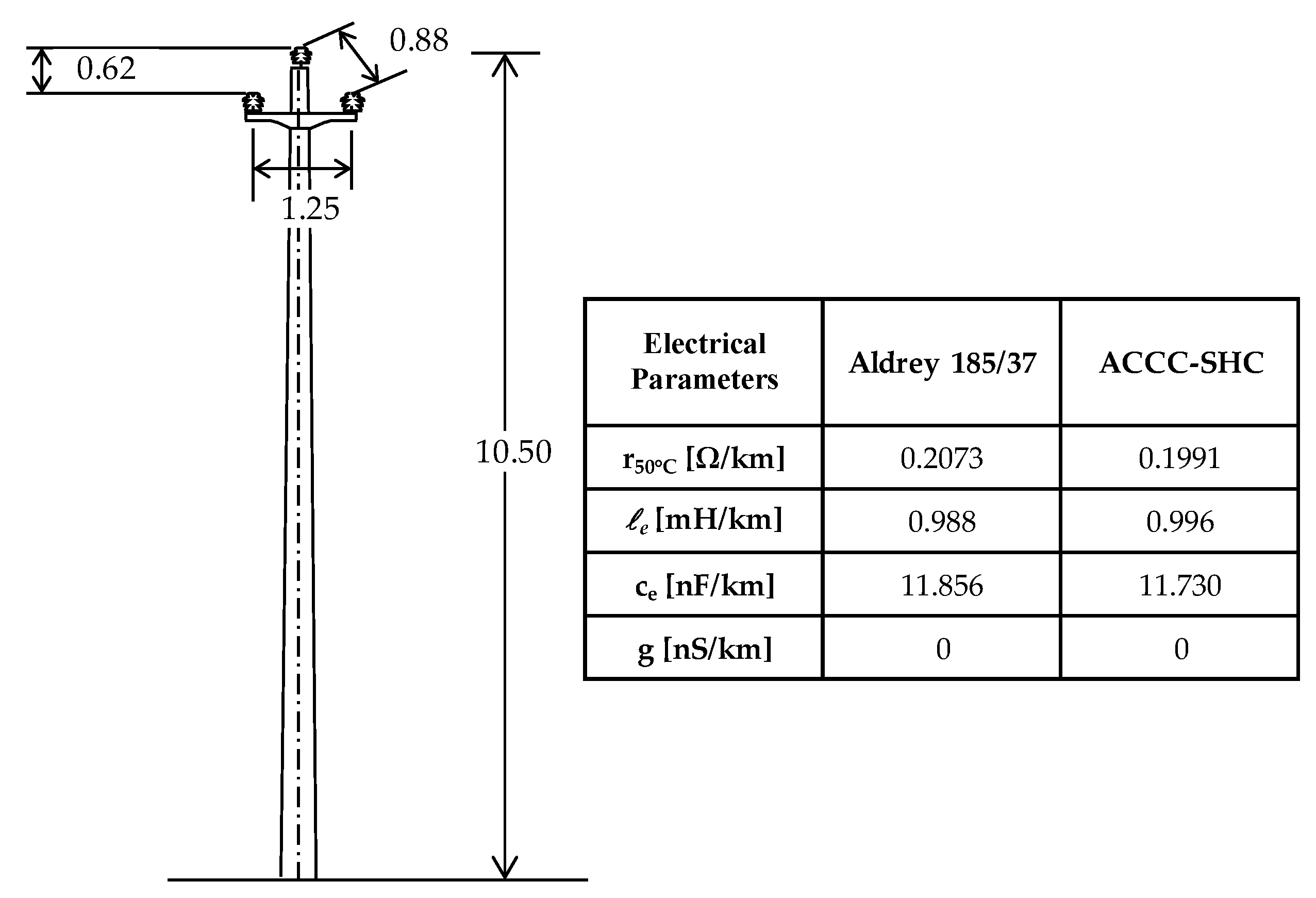
5.3. Distribution Network OHLs
6. Conclusions
Author Contributions
Funding
Conflicts of Interest
References
- Eurostat. Smarter, greener, more inclusive? Indicators to Support the Europe 2020 Strategy; Publications Office of the European Union: Brussels, Belgium, 2018. [Google Scholar]
- European Commision. Clean Energy for All Europeans. Available online: https://ec.europa.eu/energy/en/topics/energy-strategy-and-energy-union/clean-energy-all-europeans (accessed on 10 November 2018).
- ENTSO-E. Electricity Balancing in Europe. Available online: https://www.entsoe.eu/news/2018/12/12/electricity-balancing-in-europe-entso-e-releases-an-overview-of-the-european-electricity-balancing-market-and-guideline (accessed on 20 November 2018).
- Bracale, A.; Caldon, R.; Coppo, M.; Canto, D.D.; Langella, R.; Petretto, G.; Pilo, F.; Pisano, G.; Proto, D.; Ruggeri, S.; et al. Active management of distribution networks with the ATLANTIDE models. In Proceedings of the 8th Mediterranean Conference on Power Generation, Transmission, Distribution and Energy Conversion (MEDPOWER 2012), Cagliari, Italy, 1–3 October 2012. [Google Scholar]
- Petretto, G.; Cantù, M.; Gigliucci, G.; Pilo, F.; Pisano, G.; Natale, N.; Soma, G.G.; Coppo, M.; Turri, R. Representative Distribution Network Models for Assessing the Role of Active Distribution Systems in Bulk Ancillary Services Markets. In Proceedings of the 19th Power Systems Computation Conference, Genoa, Italy, 20–24 June 2016; pp. 1–7. [Google Scholar]
- Kiessling, F.; Nefzger, P.; Nolasco, J.F.; Kaintzyk, U. Overhead Power Lines-Planning, Design, Construction; (Springer, Series: Power Systems); Springer-Verlag Berlin Heidelberg: Heidelberg, Gemany, 2003. [Google Scholar]
- Benato, R.; Capra, D.; Conti, R.; Gatto, M.; Lorenzoni, A.; Marazzi, M.; Paris, G.; Sala, F. Methodologies to Assess the Interaction of Network, Environment and Territory in Planning Transmission Lines. In Proceedings of the 2006 CIGRÉ session, Paris, France, 27 August–1 September 2006. Paper C3-208. [Google Scholar]
- Benato, R.; Dambone, S.S.; Guglielmi, F. Determination of Steady-State and Faulty Regimes of Overhead Lines by Means of Multiconductor Cell Analysis (MCA). Energies 2012, 5, 2771–2793. [Google Scholar] [CrossRef]
- Usman, M.; Coppo, M.; Bignucolo, F.; Turri, R.; Cerretti, A. Multi-Phase Losses Allocation Method for Active Distribution Networks based on Branch Current Decomposition. IEEE Trans. Power Syst. 2019. [Google Scholar] [CrossRef]
- Cerretti, A.; Di Lembo, G.; Valtorta, G. Improvement in the continuity of supply due to a large introduction of Petersen coils in HV/MV substations. In Proceedings of the CIRED 2005-18th International Conference and Exhibition on Electricity Distribution, Turin, Italy, 6–9 June 2005. [Google Scholar]
- Benato, R.; Dambone, S.S.; Poli, M.; Quaciari, C.; Rinzo, G. An On-Line Travelling Wave Fault Location Method for Unearthed-Operated High Voltage Overhead Line Grids. IEEE Trans. Power Deliv. 2018, 33, 2776–2785. [Google Scholar] [CrossRef]
- Benato, R.; Caldon, R.; Coppo, M.; Dambone, S.S.; Mimo, D.; Peroni, D.; Previatello, M. Highly Efficient Overhead Line Innovative Conductors with Reduced Joule Power Losses. In Proceedings of the 2017 AEIT International Annual Conference, Cagliari, Italy, 20–22 September 2017. [Google Scholar]
- Benato, R.; Caldon, R.; Coppo, M.; Dambone, S.S.; Rinzo, G.; Mimo, D. Evaluation of Joule Power Losses Reduction in Overhead Lines with Innovative Conductors. In Proceedings of the 2018 AEIT International Annual Conference, Bari, Italy, 3–5 October 2018. [Google Scholar]
- Benato, R.; Paolucci, A. EHV AC Undergrounding Electrical Power. Performance and Planning; (Springer, Series: Power Systems); Springer-Verlag London: London, UK, 2010; Volume 47. [Google Scholar]
- Benato, R.; Napolitano, D. Overall Cost Comparison Between Cable and Overhead Lines Including the Costs for Repair After Random Failures. IEEE Trans. Power Deliv. 2012, 27, 1213–1222. [Google Scholar] [CrossRef]
- Benato, R.; Dambone, S.S.; Guglielmi, F.; Partal, E.; Tleis, N. Zero Sequence Behaviour of a Double-Circuit Overhead Line. In Proceedings of the 2014 IEEE PES T&D Conference and Exposition, Chicago, IL, USA, 14–17 April 2014. [Google Scholar]
- Benato, R.; Dambone, S.S.; Guglielmi, F.; Partal, E.; Tleis, N. Ground Return Current Behaviour in High Voltage Alternating Current Insulated Cables. Energies 2014, 7, 8116–8131. [Google Scholar] [CrossRef]
- Benato, R.; Colla, L.; Dambone, S.S.; Marelli, M. Review of High Current Rating Insulated Cable Solutions. Electr. Power Syst. Res. 2016, 133, 36–41. [Google Scholar] [CrossRef]
- Benato, R.; Dambone, S.S.; Guizzo, L.; Rebolini, M. The Synergy of the Future: High Voltage Insulated Power Cables and Railway-Highway Infrastructures. IET Gener. Transm. Distrib. 2017, 11, 2712–2720. [Google Scholar] [CrossRef]
- Benato, R.; Dambone, S.S. A New Multiconductor Cell Three-Dimension Matrix-Based Analysis Applied to a Three-Core Armoured Cable. IEEE Trans. Power Deliv. 2018, 33, 1636–1646. [Google Scholar] [CrossRef]
- Zecchino, A.; Hu, J.; Coppo, M.; Marinelli, M. Experimental Testing and Model Validation of A Decoupled-Phase on-Load Tap-Changer Transformer in An Active network. IET Gener.Transm. Distrib. 2016, 10, 3834–3843. [Google Scholar] [CrossRef]
- Cigré Technical brochure n°. Alternating Current (ac) Resistance of Helically Stranded Conductors. Ecigre, Posted 2008. Available online: https://nanopdf.com/download/alternating-current-ac-resistance-of-helically_pdf (accessed on 27 June 2009).
- Cigré Technical brochure n°. Guide for Qualifying High Temperature Conductors for Use on Overhead Transmission Lines. Ecigre, Posted 2010. Available online: https://e-cigre.org/publication/426-guide-for-qualifying-high-temperature-conductors-for-use-on-overhead-transmission-lines (accessed on 10 October 2011).
- Cigré Technical brochure n°. Conductors for the Uprating of Overhead Lines. Ecigre, Posted 2004. Available online: https://e-cigre.org/publication/244-conductors-for-the-uprating-of-overhead-lines (accessed on 18 April 2006).
- Landwehr, G.; Marais, P. Practical Comparison of Power line Upgrading and Upgrading Result. Cigré Sci. Eng. 2016, 5. (ISSN 1286-1146). [Google Scholar]
- IEEE. 738-1993-IEEE Standard for Calculating the Current-Temperature Relationship of Bare Overhead Conductors; IEEE: Piscataway, NJ, USA, 1993. [Google Scholar]
- EPRI. Demonstration of Advanced Conductors for Overhead Transmission Lines; Final Project Report; EPRI: Palo Alto, CA, USA, July 2008. [Google Scholar]
- Kumar, B.G.; Singh, R.P.; Nakamura, T. Degradation of Carbon Fiber-Reinforced Epoxy Composites by Ultraviolet Radiation and Condensation. J. Compos. Mater. 2012, 36, 2713–2733. [Google Scholar] [CrossRef]
- Fink, J.K. High Performance Polymers, 1st ed.; William Andrew: Norwich, NY, USA, 2008. [Google Scholar]
- Wright, D. Failure of Plastics and Rubber Products: Causes, Effects and Case Studies Involving Degradation; Smithers Rapra Press: Akron, OH, USA, 2001. [Google Scholar]
- CEI STANDARD 11-60. Portata al limite termico delle line elettriche aeree esterne con tensione maggiore di 100 kV; CEI: Trieste, Italy, 2002. [Google Scholar]
- ENEL; Rapporto Ambientale, 2013. Available online: https://www.enel.com/content/dam/enel-com/governance_pdf/reports/bilanci-annuali/2013/Enel_Rapporto_Ambientale_2013.pdf (accessed on 1 February 2014).
- Schurig, O.R.; Frick, C.U. Heating and Current Carrying Capacity of Bare Conductor for Outdoor Service. Gen. Electr. Rev. 1930, 33, 141–157. [Google Scholar]


| ACSR | CU | AAAC | ||||
|---|---|---|---|---|---|---|
| North | 9956 | (100.0%) | 0 | (0.0%) | 0 | (0.0%) |
| Central | 4821 | (88.2%) | 212 | (3.9%) | 435 | (8.0%) |
| South | 6198 | (94.7%) | 348 | (5.3%) | 32 | (0.5%) |
| Total | 20,975 | (95.5%) | 560 | (2.5%) | 467 | (2.1%) |
| Whole Cross-Section in (mm2) | 308 | 428 | 509 | 585 | 708 | 755 | 1865 | Total | |||
|---|---|---|---|---|---|---|---|---|---|---|---|
| Number of Subconductors per Phase | 1 | 1 | 2 | 1 | 1 | 2 | 3 | 1 | 1 | 1 | |
| North | 319 | 3147 | 483 | 957 | 1000 | 163 | 2843 | 205 | 0 | 838 | 9956 |
| 1.54% | 15.20% | 2.33% | 4.62% | 4.83% | 0.78% | 13.73% | 0.99% | 0.00% | 4.05% | 48.07% | |
| Central | 124 | 433 | 0 | 435 | 93 | 556 | 2987 | 0 | 0 | 153 | 4780 |
| 0.60% | 2.09% | 0.00% | 2.10% | 0.45% | 2.68% | 14.42% | 0.00% | 0.00% | 0.74% | 23.08% | |
| South | 0 | 11 | 0 | 620 | 96 | 311 | 2432 | 6 | 0 | 0 | 3475 |
| 0.00% | 0.05% | 0.00% | 2.99% | 0.46% | 1.50% | 11.74% | 0.03% | 0.00% | 0.00% | 16.78% | |
| Islands | 0 | 0 | 0 | 0 | 1480 | 177 | 526 | 0 | 315 | 0 | 2498 |
| 0.00% | 0.00% | 0.00% | 0.00% | 7.14% | 0.86% | 2.54% | 0.00% | 1.52% | 0.00% | 12.06% | |
| Network total | 444 | 3591 | 483 | 2012 | 2668 | 1207 | 8788 | 211 | 315 | 991 | 20,709 |
| 2.14% | 17.34% | 2.33% | 9.72% | 12.88% | 5.83% | 42.43% | 1.02% | 1.52% | 4.78% | 100.00% | |
| ACSR | AAC | CU | AAAC | |||||
|---|---|---|---|---|---|---|---|---|
| North | 8880 | (19.5%) | 356 | (0.8%) | 32,786 | (72.1%) | 2603 | (5.7%) |
| Central | 4788 | (7.3%) | 318 | (0.5%) | 59,969 | (91.9%) | 38 | (0.1%) |
| South | 16,420 | (20.2%) | 1331 | (1.6%) | 56,038 | (69.0%) | 6420 | (7.9%) |
| TOTAL | 30,090 | (15.7%) | 2005 | (1.0%) | 148,789 | (77.5%) | 9062 | (4.7%) |
| ACSR | AAC | CU | AAAC | TOT | ||||||||||
|---|---|---|---|---|---|---|---|---|---|---|---|---|---|---|
| Cross Section (mm2) | <100 | ≥100 | ≥150 | ≤25 | >25 | ≥35 | ≤16 | >16 | >25 | >35 | ≤35 | >35 | >70 | - |
| <150 | ≤35 | ≤25 | ≤35 | ≤70 | ||||||||||
| North | 305 | 264 | 8311 | 7 | 109 | 240 | 4249 | 14,364 | 4450 | 9723 | 1322 | 1077 | 204 | 45,480 |
| 0.16% | 0.14% | 4.33% | 0.00% | 0.06% | 0.13% | 2.21% | 7.49% | 2.32% | 5.07% | 0.69% | 0.56% | 0.11% | 23.70% | |
| Central | 271 | 213 | 4304 | 26 | 43 | 249 | 15,424 | 18,323 | 18,774 | 7448 | 10 | 7 | 21 | 65,236 |
| 0.14% | 0.11% | 2.24% | 0.01% | 0.02% | 0.13% | 8.04% | 9.55% | 9.78% | 3.88% | 0.01% | 0.00% | 0.01% | 34.00% | |
| South | 420 | 2542 | 5504 | 86 | 259 | 491 | 12,656 | 12,489 | 5263 | 487 | 3179 | 1458 | 55 | 45,365 |
| 0.22% | 1.32% | 2.87% | 0.04% | 0.13% | 0.26% | 6.60% | 6.51% | 2.74% | 0.25% | 1.66% | 0.76% | 0.03% | 23.64% | |
| Islands | 273 | 342 | 7339 | 1 | 172 | 322 | 5833 | 12,347 | 4935 | 2028 | 1554 | 161 | 13 | 35,809 |
| 0.14% | 0.18% | 3.82% | 0.00% | 0.09% | 0.17% | 3.04% | 6.43% | 2.57% | 1.06% | 0.81% | 0.08% | 0.01% | 18.66% | |
| Network total | 1269 | 3361 | 25,458 | 120 | 583 | 1302 | 38,162 | 57,523 | 33,422 | 19,686 | 6065 | 2703 | 293 | 191,890 |
| 0.66% | 1.75% | 13.27% | 0.06% | 0.30% | 0.68% | 19.89% | 29.98% | 17.42% | 10.26% | 3.16% | 1.41% | 0.15% | - | |
| ACSR | ACCR | G(Z)TACSR | ACCC/TW | |
|---|---|---|---|---|
| Diameter (mm) | 22.8 | 23.9 | 22.6 | 21.79 |
| Composition (mm) | 7 × 2.8 (Steel core) | 7 × 2.9 (Al core) | 7 × 2.8 (Steel core) | 7.11 (Core) |
| 26 × 3.6 (Al strands) | 26 × 3.8 (Al strands) | 10 × 3.94 (Al TW) | 16 × 4.95 (Al TW) | |
| 19 × 3.1 (Al strands) | ||||
| Cross-section (mm2) | 307.8 | 338 | 308.4 | 355.2 |
| Weight (kg/km) | 1068 | 966 | 1098 | 948 |
| Rdc20 °C (Ω/km) | 0.1063 | 0.0945 | 0.111 | 0.0887 |
| Rac20 °C (Ω/km) | 0.1065 | 0.0971 | 0.114 | 0.091 |
| Ampacity (A) | 745 | 1332 | 1128 | 1227 |
| Temperature (°C) | 75 | 210 | 210 | 180 |
| ACSR | ACCM/TW | |
|---|---|---|
| Diameter (mm) | 22.8 | 22.78 |
| Composition (mm) | 7 × 2.8 (Steel core) | 1 × 3/6 × 2.49 (Core) |
| 26 × 3.6 (Al strands) | 1 × 1 (Al shell) | |
| - | 24 × 3.13 (Al layers) | |
| Cross-section (mm) | 307.8 | 345.5 |
| Weight (kg/km) | 1068 | 989 |
| Breaking load (kN) | 97.52 | 117.39 |
| Rac20 °C (Ω/km) | 0.1065 | 0.0894 |
| Ampacity (A) | 745 | 994 |
| Temperature (°C) | 75 | 120 |
| Material Type | Permeability (cm·cm3/(m2 24 h bar)) |
|---|---|
| PEEK | 235 |
| PEKK | 796 |
| PPS | 4.2 |
| PEI | 2.3 |
| PPA | 9.7 |
| Material | Flexural Modulus (MPa) | Flexural Strength (MPa) | ||
|---|---|---|---|---|
| Before | After | Before | After | |
| PEI | 3258 | 2700 | 110 | 89 |
| PPS | 2055 | 2330 | 70 | 30 |
| Aldrey 185/37 | AAAC Al 3 | AAAC-AL-SHC | |
|---|---|---|---|
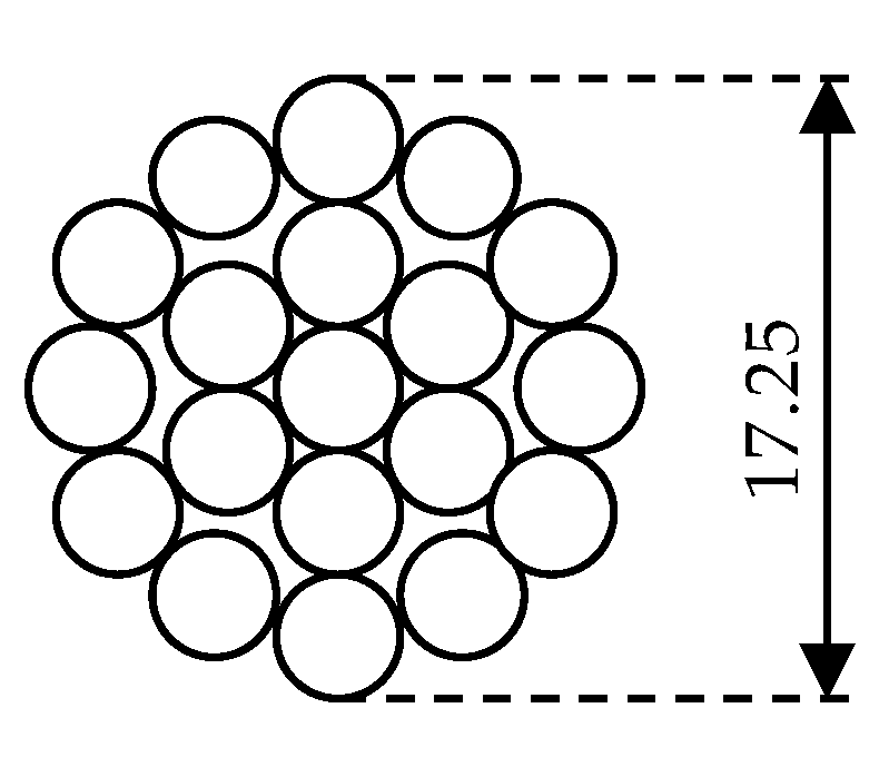
| Diameter (mm) | 17.64 | 15.25 | 17.25 |
| Composition (mm) | 37 × 2.52 | 19 × 3.45 | 19 × 3.45 |
| Cross-section (mm2) | 184.5 | 177.6 | 177.6 |
| Weight (kg/km) | 508.8 | 488 | 488 |
| Breaking load (kN) | 52.59 | 52.4 | 52.4 |
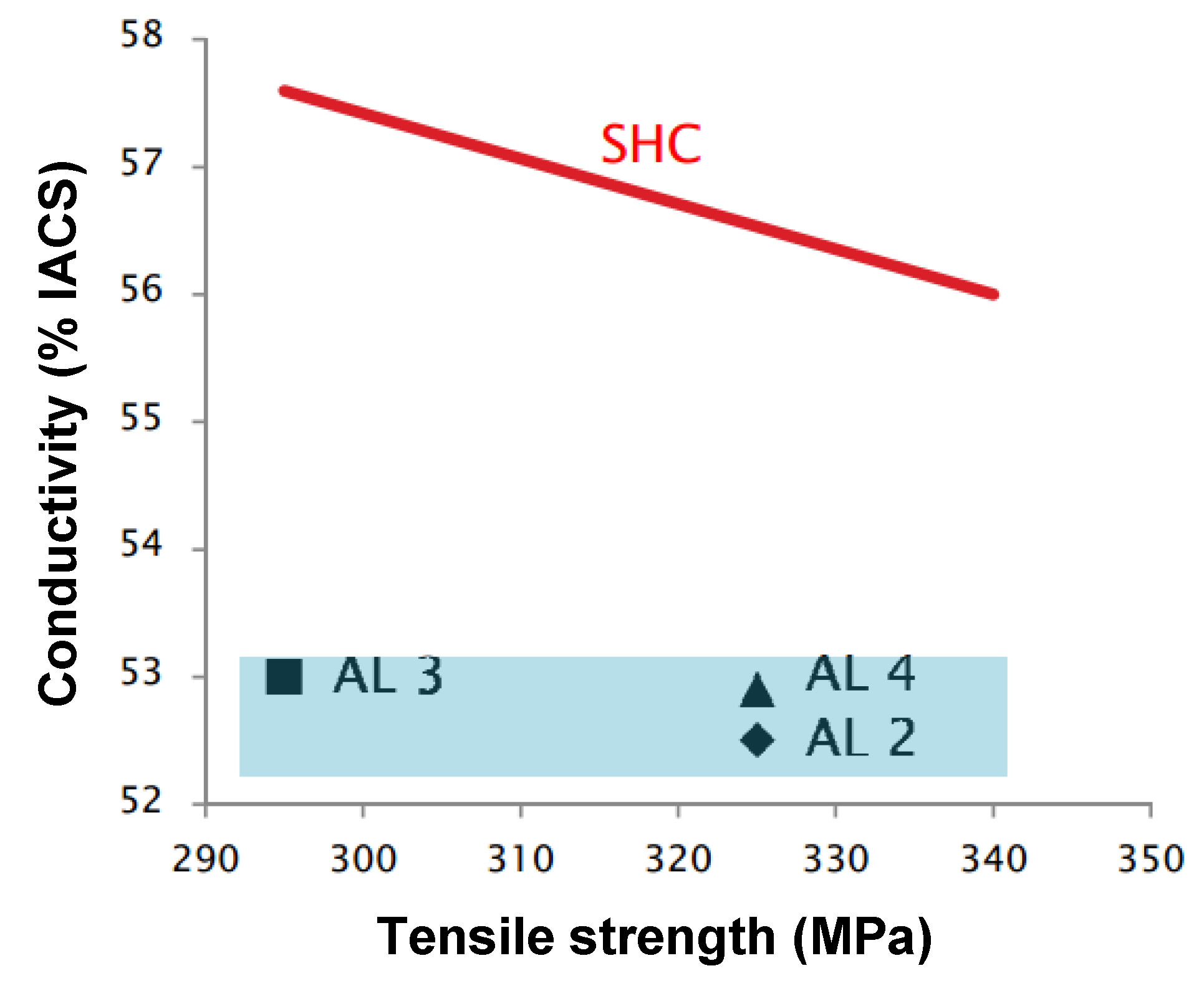
| Rac20 °C (Ω/km) | 0.1799 | 0.1862 | 0.1724 |
| IACS | 53% | 53% | 57.3% |
| Ampacity (A) | 398 | 433 | 450 |
| Temperature (°C) | 75 | 75 | 75 |
| Code | Cross-Section (mm2) | External Diameter (mm) | Breaking Load (daN) | Electrical Resistance at 20 °C (Ω/km) | Thermal Rating Current IR (A) | Thermal Rating Power PR (MW) |
|---|---|---|---|---|---|---|
| 42/6 + 1 | 42.41 | 9 | 1613 | 0.6766 | 175.9 | 113.4 |
| 68/12 + 7 | 67.69 | 13.4 | 6195 | 0.4266 | 322.9 | 208.3 |
| 128/26 + 7 | 127.6 | 15.85 | 4909 | 0.2261 | 407.1 | 262.6 |
| 191/26 + 7 | 191.2 | 19.38 | 7122 | 0.1509 | 531.4 | 342.8 |
| 212/30 + 7 | 212.0 | 21 | 9866 | 0.1362 | 589.6 | 380.3 |
| 265/26 + 7 | 264.6 | 22.8 | 9752 | 0.1090 | 655.0 | 422.5 |
| Line Voltage Rating (kV) | Thermal Limit Current of the Reference Conductor (A) | |||
|---|---|---|---|---|
| Zone A | Zone B | |||
| Period C | Period F | Period C | Period F | |
| 380 | 740 | 985 | 680 | 770 |
| 220 | 665 | 905 | 610 | 710 |
| 132 ÷ 150 | 620 | 870 | 575 | 675 |
| Losses | ACSR | ACMM/TW | ∆ | ∆% | |
|---|---|---|---|---|---|
| Annual Joule Losses (AJL) | (GWh) | 288.796 | 234.471 | 54.325 | –18.81% |
| Annual Cost of Losses (ACL) | (M€) | 11.55 | 9.379 | 2.17 | |
| Actualized Annual Cost of Losses (AACL) | (M€) | 198.22 | 160.932 | 37.288 |
| Material | Code | Cross-Section (mm2) | External Diameter (mm) | Breaking Load (daN) | Resistance at 20 °C (Ohm/km) | Thermal Rating Current IR (A) | Potential Losses Reduction (%) | Potential Losses Cost Savings (M€) | Potential CO2 Emissions Reduction (kt) |
|---|---|---|---|---|---|---|---|---|---|
| Copper | 70/19 | 68.34 | 10.7 | 27.33 | 0.2678 | 281 | 35.80 | 16.820 | 420.541 |
| 95/19 | 94.76 | 12.6 | 37.9 | 0.1831 | 357 | 5.81 | 3.000 | 75.191 | |
| Aluminium | 70/19 | 68.34 | 10.7 | 11.69 | 0.421 | 224 | 59.30 | 2.300 | 22.514 |
| 95/19 | 93.27 | 12.5 | 15.59 | 0.3085 | 274 | 44.40 | 1.890 | 18.436 | |
| 120/19 | 125.50 | 14.5 | 20.03 | 0.2292 | 332 | 24.91 | 1.157 | 11.282 | |
| Aldrey | 70/19 | 68.34 | 10.7 | 19.48 | 0.484 | 209 | 64.70 | 10.500 | 102.065 |
| 95/19 | 94.76 | 12.6 | 27.01 | 0.3491 | 258 | 50.90 | 0.490 | 4.758 | |
| 120/19 | 125.50 | 14.5 | 35.77 | 0.2636 | 310 | 34.80 | 0.360 | 3.544 | |
| 150/37 | 147.10 | 15.75 | 41.93 | 0.2253 | 344 | 23.60 | 0.260 | 2.5285 | |
| 185/37 | 184.50 | 17.64 | 52.59 | 0.1797 | 398 | 4.00 | 0.047 | 0.457 | |
| ACSR | 68/12 + 7 | 67.69 | 13.4 | 61.95 | 0.4266 | 238 | 59.90 | 5.200 | 50.771 |
| 128/26 + 7 | 127.60 | 15.85 | 49.09 | 0.2261 | 344 | 23.9 | 12.12 | 118.127 |
| Aldrey 185/37 | AAAC-SHC | ∆ | ∆% | ||
|---|---|---|---|---|---|
| Annual Joule Losses (AJL) | (GWh) | 29.316 | 28.146 | 1.170 | –4% |
| Annual Cost of Losses (ACL) | (M€) | 1.173 | 1.126 | 0.047 | |
| Actualized Annual Cost of Losses (AACL) | (M€) | 20.122 | 19.318 | 0.804 |
| Material | Code | AJL (GWh) | ACL (M€) | AACL (M€) | CO2 Emissions Saving (kt) | Joule Losses Potential Reduction (%) |
|---|---|---|---|---|---|---|
| Copper | 70/19 | 1174.173 | 46.967 | 805.900 | 420.541 | 35.8% |
| 95/19 | 1294.695 | 51.797 | 888.600 | 75.191 | 5.8% | |
| Aluminium | 70/19 | 97.283 | 3.891 | 66.785 | 22.514 | 59.3% |
| 95/19 | 106.552 | 4.262 | 73.133 | 18.436 | 44.4% | |
| 120/19 | 116.131 | 4.645 | 78.708 | 11.282 | 24.9% | |
| Aldrey | 70/19 | 404.604 | 16.184 | 277.705 | 102.065 | 64.7% |
| 95/19 | 23.973 | 0.959 | 16.454 | 4.758 | 50.9% | |
| 120/19 | 26.112 | 1.044 | 17.922 | 3.544 | 34.8% | |
| 150/37 | 27.472 | 1.099 | 18.855 | 2.5285 | 23.6% | |
| 185/37 | 29.316 | 1.173 | 20.122 | 0.457 | 4.0% | |
| ACSR | 68/12 + 7 | 217.335 | 8.693 | 149.171 | 50.771 | 59.9% |
| 128/26 + 7 | 1268.931 | 50.757 | 870.948 | 118.127 | 23.9% | |
| Total | 4786.577 | 191.471 | 3284.303 | 830.215 | 28.3% | |
© 2019 by the authors. Licensee MDPI, Basel, Switzerland. This article is an open access article distributed under the terms and conditions of the Creative Commons Attribution (CC BY) license (http://creativecommons.org/licenses/by/4.0/).
Share and Cite
Benato, R.; Caldon, R.; Chiarelli, A.; Coppo, M.; Garescì, C.; Dambone Sessa, S.; Mimo, D.; Modesti, M.; Mora, L.; Piovesan, F. CALAJOULE: An Italian Research to Lessen Joule Power Losses in Overhead Lines by Means of Innovative Conductors. Energies 2019, 12, 3107. https://doi.org/10.3390/en12163107
Benato R, Caldon R, Chiarelli A, Coppo M, Garescì C, Dambone Sessa S, Mimo D, Modesti M, Mora L, Piovesan F. CALAJOULE: An Italian Research to Lessen Joule Power Losses in Overhead Lines by Means of Innovative Conductors. Energies. 2019; 12(16):3107. https://doi.org/10.3390/en12163107
Chicago/Turabian StyleBenato, Roberto, Roberto Caldon, Antonio Chiarelli, Massimiliano Coppo, Claudio Garescì, Sebastian Dambone Sessa, Debora Mimo, Michele Modesti, Luca Mora, and Francesca Piovesan. 2019. "CALAJOULE: An Italian Research to Lessen Joule Power Losses in Overhead Lines by Means of Innovative Conductors" Energies 12, no. 16: 3107. https://doi.org/10.3390/en12163107
APA StyleBenato, R., Caldon, R., Chiarelli, A., Coppo, M., Garescì, C., Dambone Sessa, S., Mimo, D., Modesti, M., Mora, L., & Piovesan, F. (2019). CALAJOULE: An Italian Research to Lessen Joule Power Losses in Overhead Lines by Means of Innovative Conductors. Energies, 12(16), 3107. https://doi.org/10.3390/en12163107