Article

Influence of DC Electric Fields on Pollution of HVDC Composite Insulator Short Samples with Different Environmental Parameters

State Key Laboratory of Power Transmission Equipment & System Security and New Technology, Chongqing University, Chongqing 400044, China
*
Authors to whom correspondence should be addressed.
Energies 2019, 12(12), 2304; https://doi.org/10.3390/en12122304
Submission received: 6 May 2019 / Revised: 4 June 2019 / Accepted: 7 June 2019 / Published: 17 June 2019
(This article belongs to the Special Issue DC and AC Overhead Transmission Lines from Low to Extra-High Voltages)

Abstract

:
Pollution-induced flashover is a serious threat to the safe operation of power systems. With the development of High Voltage Direct Current (HVDC), it is necessary to study insulator contamination in DC electric fields. In this paper, the energized wind tunnel contamination test was conducted in order to systematically study the pollution ratio, k (ratio of non-soluble deposit density (NSDD) of a DC-energized condition to a non-energized condition), under different environmental parameters. Later, a two-dimensional contamination model of short samples of an HVDC composite insulator was established. The particle motion characteristics under different environmental parameters were then analyzed by the finite element method (FEM). The research results showed that—the DC electric field had an influence on particle motion but in different environments, the degree of influence was different. In addition, k was found to largely vary, with a variation in the environmental parameters. When the electrical stress (Es) increased from 0 to 70 kV/m, k increased gradually. However, when the wind speed (ws) increased, k experienced a decreasing trend. Finally, as the particle diameter (dp) decreased, k increased at first, followed by a decrease, and then again showed an increase. The results of the pollution ratio, k, for different environmental parameters are of great importance for guiding anti-pollution work in power systems.

1. Introduction

China has suffered increased levels of air pollution in the last three decades, due to a rapidly increasing economy, industry-dominated urbanization, and a lack of environmental protection [1]. Pollution not only affects people’s health but also harms the power system, thereby affecting social production safety. Insulator surfaces get wet under heavy pollution, fog, and rain, causing a continuous water film to form on the pollution layer, which increases the insulator surface’s conductivity. Under such conditions, the pollution flashover of insulator in transmission lines and transformer substations could easily occur [2,3,4]. Insulator pollution flashover is still a threat to the stable operation of power systems. It might cause power failure and negatively affect the social economic production [5,6,7,8]. DC electric fields have a positive impact on insulator pollution, as a result, DC electric field insulators are heavily polluted. Therefore, the operating High Voltage Direct Current (HVDC) converter station and transmission lines still experience high risks of pollution flashover [9]. Additionally, the composite insulator has been widely used in the HVDC transmission lines of China and other countries for decades, on the merits of its anti-pollution property, low weight, and good mechanical strength, compared to porcelain and glass insulators. Therefore, it is more and more necessary to study the contamination of composite insulators in the DC electric field.
A large number of research studies have been conducted recently, through simulation and contamination tests, to study the contamination mechanism of insulators. By simplifying the wind tunnel pollution test, a power law relationship between the pollution accumulation rate and wind speed was proposed in [10]. In [11], a rail insulator pollution deposition model was established by using gas–solid aerosol flow simulation, and the influence of wind speed on pollution deposition and distribution was revealed. Additionally, the relationship between particle diameter, wind speed, particle volume fraction, contamination degree, and contamination distribution were studied in [12], by establishing an Eulerian multiphase simulation model.
In addition to the above-mentioned studies, others have also reported on contamination in electric fields [9,13,14,15,16,17,18]. For example, the non-uniform distribution of composite insulators was studied in [9], then electric field force on contaminated particles was obtained by the coupling-physics model, and the mechanism of non-uniform distribution of contamination was further explained. Reference [13] proposed that the electric force between insulator sheds would change the particle’s tracks; their trajectories are determined by electric force when the particle diameter is within 1–10 μm. However, the trajectories are affected by air drag force when particle diameter is over 10 μm. The above-mentioned studies have shown that contamination is affected by electric fields, and have provided essential information for the performances of insulator contamination. However, few research studies have presented a quantitative and systematic analysis of pollution ratio k with different environmental parameters.
In this study, a wind tunnel contamination test was conducted, in order to carry out a systematic study on the pollution ratio k, under different environmental parameters. In order to explore the mechanism of the effect of DC electric fields on particle motion, force analysis of the polluted particles has been carried out in this paper. Then, the electric field and electric field force calculation methods have been introduced. Particle motion toward insulator strings in different environment parameters have further been presented through the FEM simulation method. The results of the pollution ratio k under different environmental parameters, provides a guidance for insulation selection and anti-pollution field work in power systems, which could help prevent pollution-induced flashover accidents and maintain social production safety.

2. Wind Tunnel Pollution Experiment

2.1. Samples

Samples in this paper were short samples of HVDC composite insulators. Structure and technical parameters of the sample are shown in Figure 1 and Table 1, where D1 is a big-shed diameter, D2 is small-shed diameter, and H is structure height.
The contaminated particles were simulated by SiO2 powder. SiO2 powder with particle sizes (Sp) of 250, 400, 800, and 2000 mesh were obtained after screening with different screen meshes. Of note, the average diameter of 250 mesh SiO2 powder was the largest, followed by 400, 800, and 2000 mesh. The relationship between dp and Sp has been presented in [9].

2.2. Experimental Devices

The experiments were conducted in a cyclic wind tunnel [9]; shown in Figure 2. The maximum wind speed could reach 7 m/s. In addition, a six angle cellular was installed to decrease the airflow turbulence. A deflector was also equipped to equalize the airflow. Other test devices included temperature hygrometer, scrubbing tools, electronic balance, anemometer, air particulate matter collection instrument, etc. The power supply in this test was provided by the test transformer (YDTW-50/50 kVA).

2.3. Methods of the Wind Tunnel Test

Test procedures were as follows. First, all surfaces of the short samples were washed thoroughly to further remove contamination. Then, the samples were put in a clean and dry place to dry them for the contamination test. After this, ws, particle concentration (pc), and the relative humidity (RH) were kept stable. Afterwards, one string composite insulator was suspended in the wind tunnel. Withstand voltage gradient of the insulation should have been over 70 kV/m, according to the 500 kV design experience of transmission lines [19]. Therefore, in this study, the short sample was energized with DC 35 kV voltage (70 kV/m). To study the effect of the electric field intensity on contamination, due to the limitation of wind tunnel size, the short samples were energized with a voltage of DC 35 kV (70 kV/m), 22 kV (44 kV/m), 11 kV (22 kV/m), and 0 (0 kV/m). The contamination particles were accumulated in 8 h.
When the test was completed, the samples were taken carefully out of the wind tunnel, and contamination on the tested insulator surface was subsequently measured to check the contamination mass (mg). The contamination measurement methods are shown in Figure 3. More concretely, the clean filtration membrane was first weighed. Then, the polluted liquid was filtered after cleaning the insulator. The SiO2 powder left on the filtration membranes were dried and weighed. Finally, non-soluble deposit density (NSDD) was calculated by referring to the weighing results and the surface area of the insulator. The standard IEC (IEC Standard 60507) measuring process was followed to obtain the NSDD.

3. Wind Tunnel Test Results

3.1. Contamination Degree of Short Samples

The ws was 6 m/s, the Sp was 400 mesh, and the RH was 60%. The contamination distribution of short samples under different electrical stress is shown in Figure 4.
As is shown in Figure 4, the influence of the DC electrical field on contamination was distinct. Contamination on the surface of the short samples in the DC energized condition was more serious than that in the non-energized condition. In addition, with the increment of electrical stress, pollution became more and more serious.

3.2. NSDD of Insulators under Different Environmental Parameters

Further, NSDD of the tested insulator under different environmental parameters could be obtained, as shown in Table 2, Table 3, Table 4 and Table 5.
As is shown in Table 2, Table 3, Table 4 and Table 5, the following conclusions could be drawn. First, electrical stress had a great influence on the NSDD of insulators in the wind tunnel test, especially in the case of high electrical stress. Under similar conditions of other environmental parameters (ws = 1 m/s, Sp = 250 mesh), NSDD under electrical stress of 70 kV/m was 2.3 times larger than that of the non-energized condition, which showed that the accumulation of contamination under the DC electric field was different from that under the non-energized condition.
In addition, NSDD varied greatly under different environmental parameters, specifically, NSDD was greatly influenced by ws, Sp, and Es. With the increase of ws and Es, NSDD increased gradually. By contrast, with the increase of Sp, NSDD decreased gradually because the particles with a smaller Sp tended to cluster more easily. The experimental results of NSDD in different environments are the same as those in previous literatures [9,12,20]. However, there has been no systematic study on the pollution ratio k. Therefore, the discussion section of this paper focuses on the pollution ratio k. Before the discussion of k, in order to explore the effect of DC electric fields on particle motion, force analysis of the polluted particles has been carried out in Section 4. Further, a two-dimensional contamination model of the short samples of HVDC composite insulator has been established. Then, particle motion characteristics under different environmental parameters have been analyzed through FEM.

4. Motion Process of the Particles under DC Electric Fields

4.1. Force Analysis of Particles

In order to study the movement process of contaminated particles, force analysis of the contaminated particles has been discussed first. The movement process of the charged contaminated particles is mainly determined through gravity (Fg), fluid drag force (Fd), electrical force (Fe), and polarization force (Fp) [21]. Fp, Fe (determined by the electrical field), Fd, and Fg can be expressed through Equations (1)–(4):
F p = 2 π ( d p 2 ) 3 ε 0 × ε p 1 ε p + 2 ( E 2 )
where dp is the particle diameter(m); E is the electrical field (V/m); ε 0 is the vacuum permittivity (8.85 × 10⁻¹² F/m); and ε p is particles relative dielectric constant.
F e = Q p E
Qp is the charge of the contaminated particles (C), which can be written as Equation (5).
F d = 3 π μ d p ( w s v p )
where vp is the contaminated particles speed and μ is air dynamic viscosity.
F g = 4 3 ρ p g π ( d p 2 ) 3
where g is the gravitational acceleration (9.8 m/s 2) and ρp is the density of particles (kg/m3).
Q p = 3 π ε 0 E d p 2 ( ε p ε p + 2 ) / e
where e is the elementary charge quantity (1.6022 × 10⁻¹⁹ C). Then, the dynamic equation of particles can be achieved as follows:
d ( m p v p ) d t = F p + F e + F d + F g
where mp is the particles quality (kg) and t is the time of movement (s).

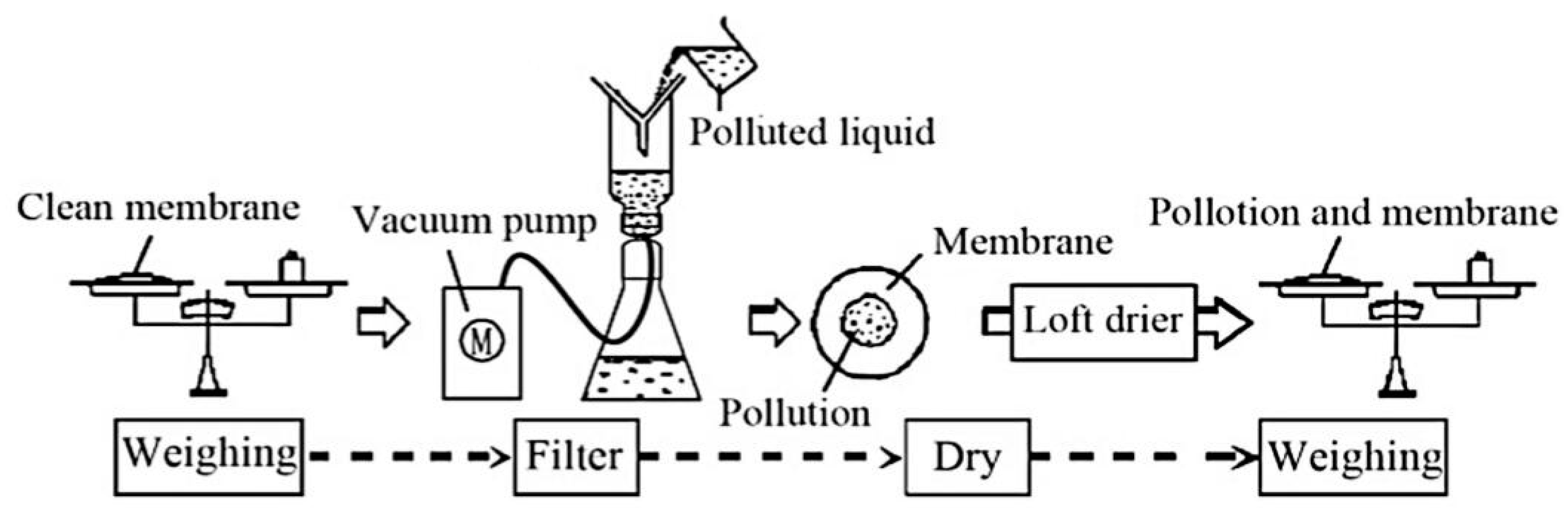
4.2. Electric Field Simulation

In this paper, a multi-physical field simulation software (Comsol) was used to calculate the electric field around the short sample of HVDC insulator strings, based on FEM. Under direct current, the electric field calculation domain governing the equations were as follows:
D = ρ ,   E = V ,   D = ε 0 ε 1 E
ρ is the charge density (C/m3); D is the electric flux density (C/m2); V is the electric potential (V); and ε 1 is the relative dielectric constant; which is 3.3 for silicon rubber. The 2D FEM simulation model was established by referring to the real-scale structure parameters of short samples.
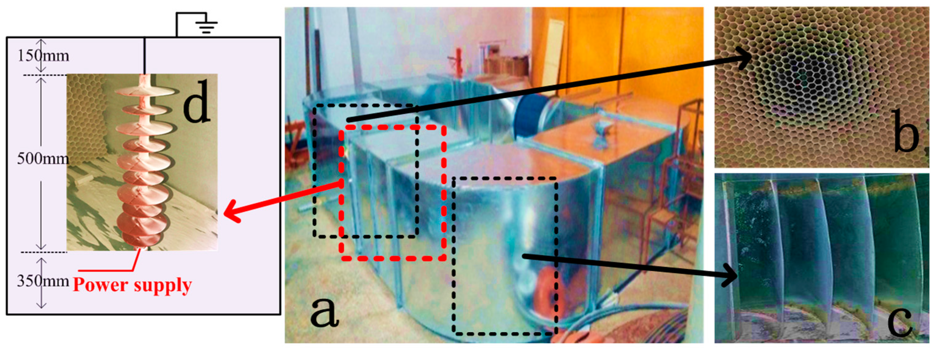
In the simulation model, the electrostatic field module and the fluid flow module were used for the coupling calculation, and a rectangular boundary was added around the insulator string, according to the dimensions of the wind tunnel. The boundary electric potential was set to 0, in the calculation region. Additionally, the short sample was defined with an Es of 70, 44, and 22 kV/m.

4.3. Effects of the Environment Parameters on Particles Motion Toward Insulator String

In [22], it was concluded by means of numerical calculations that Fp of contaminated particles in an electric field is much smaller than that of Fe, and the Fp can be neglected. Therefore, in order to reduce the computational load, only the main force (Fe, Fd, and Fg) of the contaminated particles were considered in the calculation model of this paper.
A multi-physical field simulation software was used to simulate the trajectory of particle motion and the trajectory of particles motion affected by Fe, Fd, and Fg. It should be mentioned that, first, the electric field around the insulator was calculated, where a steady-state model and a direct solver was used. The coupling effect between the electric field and the flow field was further calculated, where the transient model and an iterative solver was used. Supposing that when the particles reached the insulator surface they stopped moving, then by setting the wall boundary condition on the insulator surface to “freeze”, the end velocity and trajectory of particles from the outside air flow to the insulator surface could be recorded. For example, 
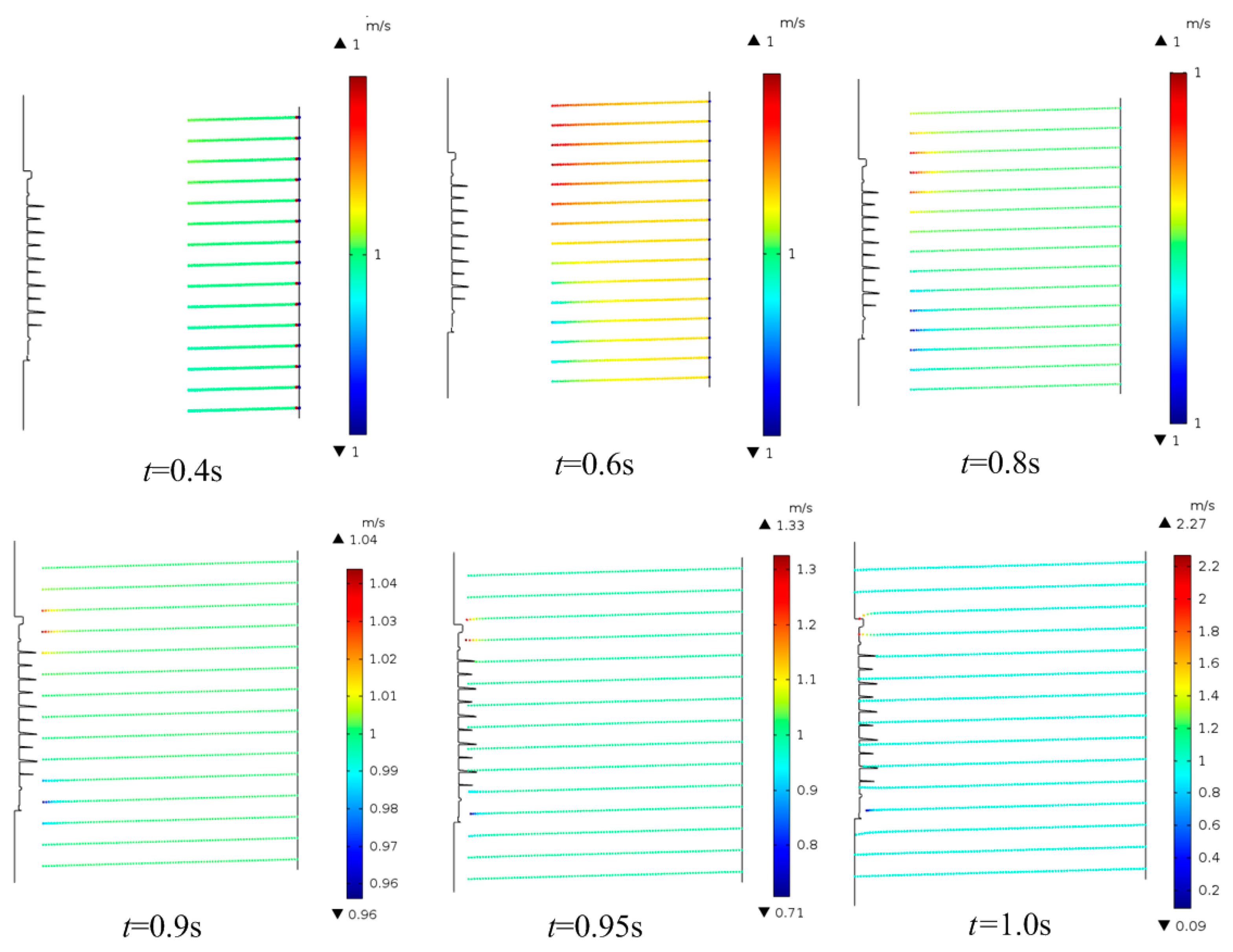
Figure 5 shows the simulation results of the particle movement process when ws = 1 m/s and dp = 20 μm energized the short sample with an Es of 70 kV/m.
Figure 5 shows that, initially, Fd played a major role in the particle movement, and the contaminated particles move to the insulator surface in a straight line, at a constant speed, under the action of air resistance and gravity balance force. However, when the contaminated particles were close to the insulator string, the motion speed of the contaminated particles changed due to the action of Fe. Specifically, the velocity of the particles had hardly changed before 0.4 s. When the motion time reached 0.6 s, a velocity change of particles (observed from color) was found in the picture, but the value was still about 1 m/s. At 0.9 s, the particle velocity changed numerically. The maximum velocity of particle motion was 1.04 m/s and the minimum velocity was 0.96 m/s. Finally, at 1 s, the particles had collided with the insulator surface and the terminal velocity (vt) had changed significantly. The maximum velocity of the particle motion could reach 2.27 m/s and the minimum velocity was 0.09 m/s. Therefore, it could be concluded that the DC electric field had a greater influence on the particle motion around the insulator. To study particle motion of different environmental parameters, particle motion under different wind speeds, particle diameters, and electrical stress, was calculated. The calculated results are shown in Figure 6, Figure 7 and Figure 8.
Reference [20] shows that pollution increased with the increment of ws, within a certain range of ws. In addition, the process of collision and adhesion between the contaminated particles and insulator surface was very complex, so in this work only the vt was studied under different environmental parameters, which was used to characterize the effect of the electric field on contamination.
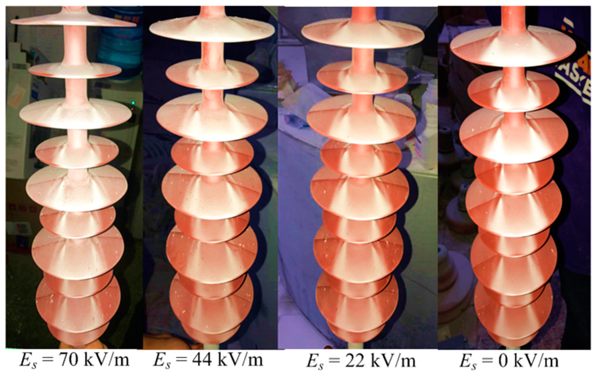
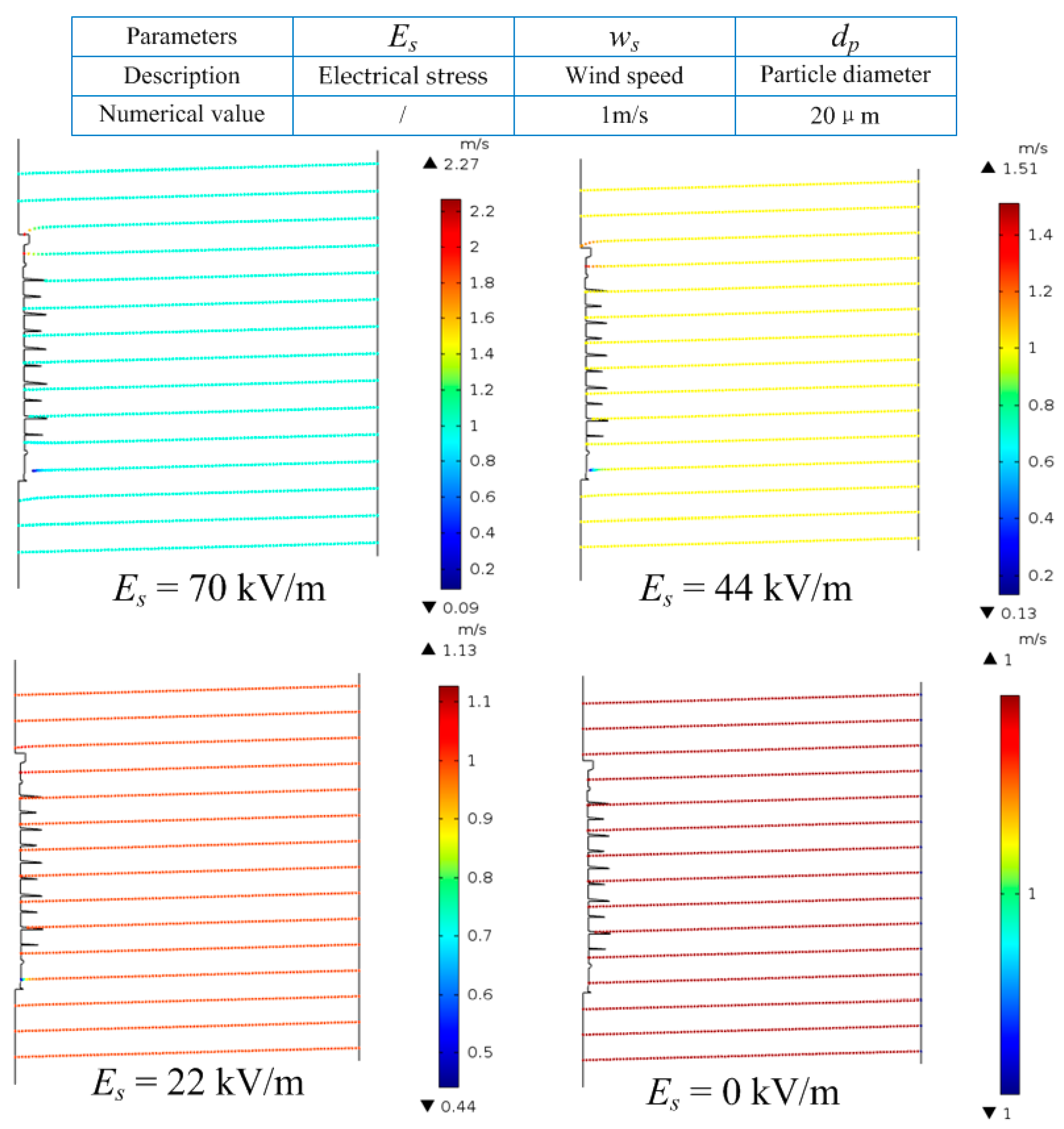
Figure 6 shows the obvious effect of electrical stress on particle motion. Specifically, when Es was 0, 22, 44, and 70 kV/m, the maximum speed of the particles reaching the insulator was 1, 1.13, 1.51, and 2.27 m/s, respectively. The particle velocities increased by 13% (22 kV/m), 51% (44 kV/m), and 127% (70 kV/m), respectively, compared to that without an electric field.
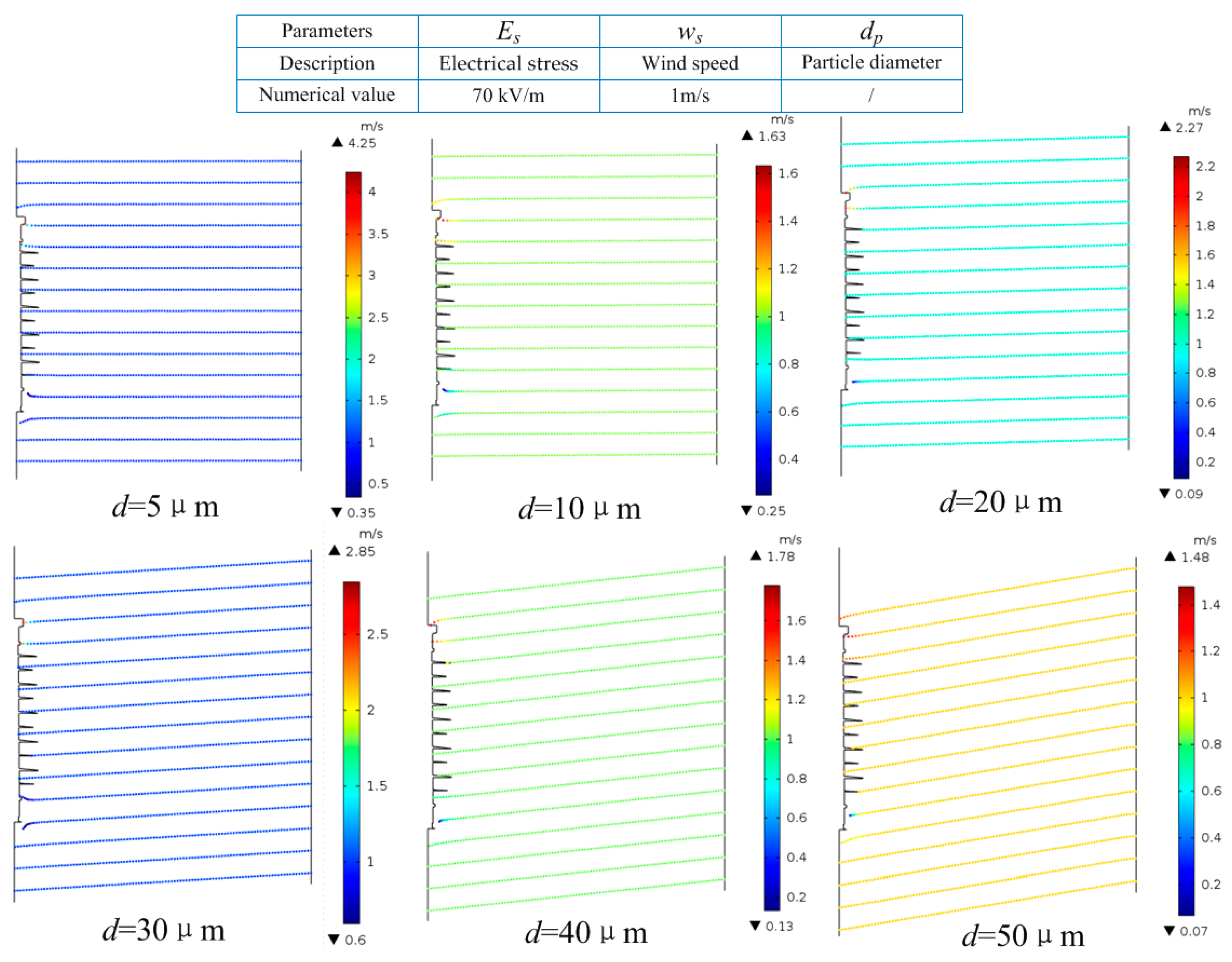
Figure 7 shows the effect of particle diameter on particle motion. When 70 kV/m electrical stress was applied and ws was 1 m/s, the motion of particles with diameters of 5, 10, 20, 30, 40, and 50 μm was calculated, as shown in Figure 7. vt of particles with diameters of 5 μm ranked at the top, standing at 4.25 m/s, by contrast, vt of particles with diameters of 50 μm was the minimal, with nearly 1.48 m/s. Of note, as the diameter increased, vt did not always decrease. vt increased by 325% (5 μm), 63% (10 μm), 127% (20 μm), 185% (30 μm), 78% (40 μm), and 48% (50 μm), respectively, compared to that without an electric field.
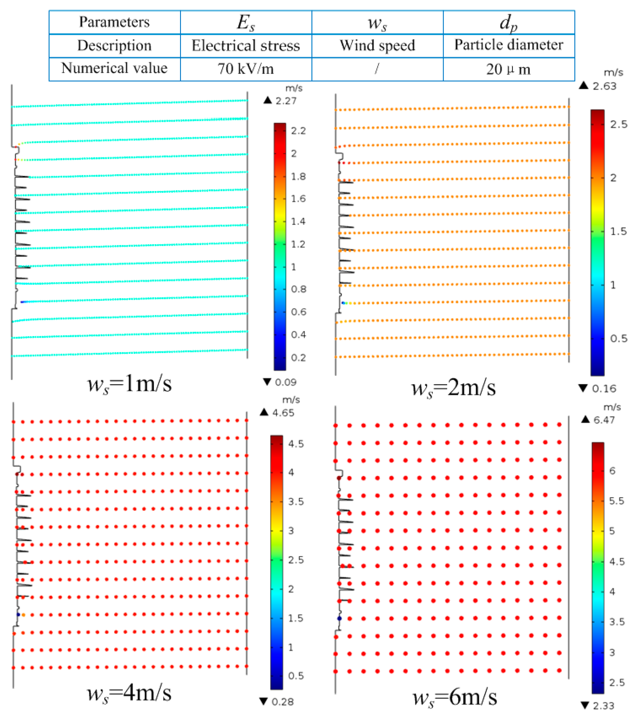
Figure 8 shows the effect of wind speed on particle motion. It can be seen that with the increment of ws, the influence of electric field on particle motion was gradually weakened. More concretely, vt increased by 127% (1 m/s), 31.5% (2 m/s), 16.25% (4 m/s), and 7.83% (6 m/s), compared to that without an electric field.
In this section, the effect of electric field on particle motion under different environmental parameters was preliminarily explored by means of simulation calculation. The effects of electrical stress, wind speed, and particle diameter on particle motion were obtained. In order to obtain the pollution ratio k under different environmental parameters, the results of the wind tunnel contamination experiment were further analyzed in this paper.

5. Discussion

5.1. Pollution Ratio k under Different Environmental Parameters

This paper presents the effect of electric fields on pollution of insulator surfaces, for which the movement characteristics of polluted particles was analyzed. Previous studies have mostly focused on the non-electrified contamination process, but electrified contamination results are needed as a guide for power system workers, for cleaning up contamination on insulator surfaces. There are also studies on the contamination of insulators in operating HVDC transmission lines, but there is yet no systematic study on the pollution ratio k under different environmental parameters. Therefore, this section will calculate and analyze the contamination coefficients of different environmental parameters, which would provide guidance for anti-pollution efforts in power systems. According to the results in Table 2, Table 3, Table 4 and Table 5, the pollution ratio k could be calculated as shown in Table 6, Table 7 and Table 8.
As shown in Table 6, Table 7 and Table 8, the following conclusions could be drawn. First, the value of k varied greatly under different environmental parameters. The maximum k value in this wind tunnel test was 3.118 (Es = 70 kV/m, ws = 1 m/s, and Sp = 2000 mesh) and the minimum k value was only 1.081 (Es = 22 kV/m, ws = 6 m/s, and d = 250 mesh). Even at the same Es, the value of k fluctuated greatly. Take Es = 70 kV/m as an example, k varied between 3.118 (ws = 1 m/s and d = 2000 mesh) and 1.807 (ws = 6 m/s and Sp = 250 mesh).
Second, with the increase of Es, k increased gradually. Taking ws = 1 m/s and Sp = 250 mesh as an example, when Es increased from 22 kV/m to 70 kV/m, k increased from 1.365 to 2.308 correspondingly.
In addition, with the increase of ws, k experienced a decreasing trend. Taking Es = 70 kV/m and Sp = 250 mesh as an example, when the ws increased from 1 m/s to 6 m/s, k decreased from 2.038 to 1.807. Finally, as the Sp decreased (From 250 to 2000 mesh), k increased first, then decreased, and then increased again. Taking ws = 1 m/s and Es = 70 kV/m as an example, the k value was 2.308, 2.935, 2.569, and 3.118, when Sp was 250, 400, 800, and 1000 mesh, respectively.
It is important to highlight that the test results of the pollution ratio k was consistent with the vt calculated above, which showed that the simulation method used in this paper could provide a reference for the study of k value when it is difficult to carry out an experiment.

5.2. Future Research Directions

This research work carried out an extensive study on the effect of DC electrical fields on contamination as well as the pollution ratio k. However, further work is needed to apply the research results to the operations of a power system. Due to the limitations of the size of the wind tunnel and the experimental conditions, in this work, only the variation of k at 35 kV and lower voltage levels was studied. Whether the variation of k in different environments at higher voltage levels is consistent with the results of this study is a problem that needs further investigation.

6. Conclusions

A wind tunnel contamination test was conducted, in order to carry out a systematic study on the pollution ratio k under different environmental parameters. After this, force analysis (electric field force, polarization force, air drag force, and gravity) of the polluted particles was carried out, then, the electric field and electric field force calculated method were further introduced, and particle motion toward insulator string, in different environment parameters, were presented. Finally, both NSDD and pollution ratio k was obtained. The following conclusions could be drawn:
(1) DC electric field had a great influence on particle motion but in different environments, the degree of influence was different. As the particle diameter increased, vt did not always decrease. vt increased by 325% (5 μm), 63% (10 μm), 127% (20 μm), 185% (30 μm), 78% (40 μm), and 48% (50 μm), respectively, compared to that without an electric field. With the increment of ws, the influence of the electric field on particle motion was gradually weakened.
(2) NSDD varied greatly under different environmental parameters, specifically, NSDD was greatly influenced by ws, Sp, and Es. With the increase of ws and Es, NSDD gradually increased. By contrast, with the increase of Sp, NSDD gradually decreased.
(3) First, the value of k varied greatly under different environmental parameters. Second, with the increment of Es, k increased gradually. In addition, with the increment of ws, k experienced a decreasing trend. Taking Es = 70 kV/m and Sp = 250 mesh as an example, when the ws increased from 1 m/s to 6 m/s, k decreased from 2.038 to 1.807. Finally, as the Sp decreased (from 250 mesh to 2000 mesh), k first increased, then decreased, and then increased again.
(4) The test results of pollution ratio k was consistent with the vt calculated above, which showed that the simulation method used in this paper could provide a reference for the study of k value, when the experiment was difficult to carry out.

Author Contributions

X.J. and Z.Z. conceived and designed the experiments; X.Q. performed the experiments and simulations; X.Q. and Z.Z. analyzed the data; T.L. contributed material tools; and X.Q. wrote the paper.

Funding

This research was funded by the National Key Research and Development Program of China under Grant [2016YFB0900900], the Graduate Research and Innovation Foundation of Chongqing, China [Grant No. CYB18010], and the Fundamental Research Funds for the Central Universities, Project No. 2019CDXYDQ0010.

Conflicts of Interest

The authors declare no conflict of interest.

References

  1. Zhao, D.; Chen, H.; Li, X. Air pollution and its influential factors in China’s hot spots. J. Clean. Prod. 2018, 185, 619–627. [Google Scholar] [CrossRef]
  2. Zhang, Z.; Qiao, X.; Zhang, Y. AC flashover performance of different shed configurations of composite insulators under fan-shaped non-uniform pollution. High Volt. 2018, 3, 199–206. [Google Scholar] [CrossRef]
  3. Sima, W.; Yuan, T.; Yang, Q.; Xu, K.; Sun, C. Effect of non-uniform pollution on the withstand characteristics of extra high voltage (EHV) suspension ceramic insulator string. IET Gener. Transm. Distrib. 2010, 4, 445–455. [Google Scholar] [CrossRef]
  4. Naito, K.; Hasegawa, Y.; Imakoma, T. Improvement of the DC voltage insulation efficiency of suspension insulators under contaminated conditions. IEEE Trans. Dielectr. Electr. Insul. 1988, 23, 1025–1032. [Google Scholar] [CrossRef]
  5. Baker, A.C.; Farzaneh, M.; Gorur, R.S. Insulator selection for overhead AC lines with respect to contamination. IEEE Trans. Power Deliv. 2009, 24, 1633–1641. [Google Scholar] [CrossRef]
  6. Zhang, Z.; Jiang, X.; Cao, Y. Influence of Low Atmospheric Pressure on AC Pollution Flashover Performance of Various Types Insulators. IEEE Trans. Dielectr. Electr. Insul. 2010, 17, 425–433. [Google Scholar] [CrossRef]
  7. Jiang, X.; Wang, S.; Zhang, Z. Investigation of Flashover Voltage and Non-uniform Pollution Correction Coefficient of Short Samples of Composite Insulator Intended for ±800kV UHVDC. IEEE Trans. Dielectr. Electr. Insul. 2010, 17, 71–79. [Google Scholar] [CrossRef]
  8. Gouda, O.E.; El Dein, A.Z. Laboratory simulation of naturally polluted high-voltage transmission line insulators. IET Gener. Transm. Distrib. 2014, 8, 321–327. [Google Scholar] [CrossRef]
  9. Zhang, Z.; Qiao, X.; Yang, S.; Jiang, X. Non-Uniform Distribution of Contamination on Composite Insulators in HVDC Transmission Lines. Appl. Sci. 2018, 8, 1962. [Google Scholar] [CrossRef]
  10. Ravelomanantsoa, N.; Farzaneh, M.; Chisholm, W.A. A Simulation Method for Winter Pollution Contamination of HV Insulator. In Proceedings of the 2011 EIC Annapolis, Annapolis, MD, USA, 5–8 June 2011; pp. 373–376. [Google Scholar]
  11. Sun, J.; Gao, G.; Zhou, L.; Wu, G. Pollution accumulation on rail insulator in high-speed aerosol. IEEE Trans. Dielectr. Electr. Insul. 2013, 20, 731–738. [Google Scholar]
  12. Zhang, Z.; Zhang, W.; You, J.; Jiang, X.; Zhan, D.; Bi, M.; Wu, B.; Wu, J. Influence factors in contamination process of XP-160 insulators based on computational fluid mechanics. IET Gener. Transm. Distrib. 2016, 10, 4140–4148. [Google Scholar] [CrossRef]
  13. Horenstein, M.N.; Melcher, J.R. Particle Contamination of High Voltage DC Insulators below Corona Threshold. IEEE Trans. Dielectr. Electr. Insul. 1979, 16, 297–305. [Google Scholar] [CrossRef]
  14. Lv, Y.; Li, J.; Zhan, X.; Pang, G. A simulation study on pollution accumulation characteristics of XP13-160 porcelain suspension disc insulator. IEEE Trans. Dielectr. Electr. Insul. 2016, 23, 2196–2206. [Google Scholar] [CrossRef]
  15. Wu, X.; Zhang, X.; Wu, G. Simulation and Analysis of Contamination Depositing Characteristic of Roof Insulator. In Proceedings of the 2016 IEEE International Conference on High Voltage Engineering and Application (ICHVE), Chengdu, China, 19–22 September 2016; pp. 1–4. [Google Scholar]
  16. Chao, Y.; Huang, F.; Zhao, S.; Wang, C.; Wang, F.; Yue, Y. Study on Natural Pollution Accumulating Characteristics of Cap and Pin Suspension Ceramic Insulator with Composite Shed of DC 500kV Transmission Line in Central China. In Proceedings of the 2016 IEEE International Conference on High. Voltage Engineering and Application (ICHVE), Chengdu, China, 19–22 September 2016; pp. 1–4. [Google Scholar]
  17. Liu, Q. Investigation on Natural Contamination Deposition of Insulators on ±500kV DC Transmission Lines in Different Environments. In Proceedings of the 2013 Annual Report Conference on Electrical Insulation and Dielectric Phenomena, Shenzhen, China, 20–23 October 2013; pp. 347–349. [Google Scholar]
  18. Zhang, D.; Zhang, Z.; Jiang, X. Simulation Study on the Effects of DC Electric Field on Insulator Surface Pollution Deposit. Energies 2018, 11, 626. [Google Scholar] [CrossRef]
  19. Jiang, X.; Shu, L.; Sun, C. Power System Pollution and Iced Insulation; Chinese Electric Power Press: Beijing, China, 2009. (In Chinese) [Google Scholar]
  20. Zhang, Z.; You, J.; Zhao, J. Contamination characteristics of disc-suspension insulator of transmission line in wind tunnel. IET Gener. Transm. Distrib. 2017, 11, 1453–1460. [Google Scholar] [CrossRef]
  21. Gao, B.; Yang, F.; Songyang, Z. The Movement Characteristics of Charged Haze Particles in Ionized Field and Its Influence on Contamination of Insulator. IEEE Trans. Magn. 2018, 54. [Google Scholar] [CrossRef]
  22. Zhang, D.; Zhang, Z.; Jiang, X. Wind Tunnel DC Contamination Performance of Typical Suspension Insulator and Its Analysis. Trans. Chin. Electrotech. Soc 2018, 30, 4636–4645. (In Chinese) [Google Scholar]
Figure 1. Short samples of High Voltage Direct Current (HVDC) composite insulators.
Energies 12 02304 g001
Figure 2. Wind tunnel test devices: (a) Wind tunnel; (b) six angle cellular; (c) deflector; and (d) the wind tunnel insulator.
Energies 12 02304 g002
Figure 3. The measuring method of contamination.
Energies 12 02304 g003
Figure 4. Contamination degree of short samples.
Energies 12 02304 g004
Figure 5. The particle movement process.
Energies 12 02304 g005
Figure 6. Particle movement under different electrical stress.
Energies 12 02304 g006
Figure 7. Particle movement with different particle diameter.
Energies 12 02304 g007
Figure 8. Particle movement with different wind speeds.
Energies 12 02304 g008
Table 1. Structure parameters of the tested insulators.
SampleMaterialParameters (mm)
D1D2H
Short sample of HVDC composite insulatorSilicon rubber135105500
Table 2. Non-soluble deposit density (NSDD) under electrical stress of 70 kV/m.
ws (m/s)NSDD (mg/cm2); 70 kV/m
Sp = 250 MeshSp = 400 MeshSp = 800 MeshSp = 2000 Mesh
10.120.1350.1670.212
20.1280.1470.2810.341
40.1650.1870.3650.426
60.2440.30.5620.613
Table 3. NSDD under electrical stress of 44 kV/m.
ws (m/s)NSDD (mg/cm2); 44 kV/m
Sp = 250 MeshSp = 400 MeshSp = 800 MeshSp = 2000 Mesh
10.0990.1140.1420.187
20.110.1280.2410.284
40.1370.1570.3120.359
60.2140.250.4720.523
Table 4. NSDD under electrical stress of 22 kV/m.
ws (m/s)NSDD (mg/cm2); 22 kV/m
Sp = 250 MeshSp = 400 MeshSp = 800 MeshSp = 2000 Mesh
10.0710.0850.1020.125
20.0780.0890.1730.219
40.1030.1210.230.236
60.1460.180.3390.365
Table 5. NSDD under Non-energized condition.
ws (m/s)NSDD (mg/cm2); Non-Energized Condition
Sp = 250 MeshSp = 400 MeshSp = 800 MeshSp = 2000 Mesh
10.0520.0460.0650.068
20.0630.0560.1270.12
40.0840.0750.1710.158
60.1350.140.2970.271
Table 6. Pollution ratio k under electrical stress of 70 kV/m.
ws (m/s)Pollution Ratio k; 70 kV/m
Sp = 250 MeshSp = 400 MeshSp = 800 MeshSp = 2000 Mesh
12.3082.9352.5693.118
22.0322.6252.2132.842
41.9642.4932.1352.696
61.8072.1431.8922.262
Table 7. Pollution ratio k under electrical stress of 44 kV/m.
ws (m/s)Pollution Ratio k; 44 kV/m
Sp = 250 MeshSp = 400 MeshSp = 800 MeshSp = 2000 Mesh
11.9042.4782.1852.750
21.7462.2861.8982.367
41.6312.0931.8252.272
61.5851.7861.5891.930
Table 8. Pollution ratio k under electrical stress of 22 kV/m.
ws (m/s)Pollution Ratio k; 22 kV/m
Sp = 250 MeshSp = 400 MeshSp = 800 MeshSp = 2000 Mesh
11.3651.8481.5691.838
21.2381.5891.3621.825
41.2261.6131.3451.494
61.0811.2861.1411.347

