Article

Modeling and Stability Analysis of Model Predictive Control Dual Active Bridge Converter

The State Key Laboratory of Electrical Insulation and Power Equipment, Shaanxi Key Laboratory of Smart Grid, School of Electrical Engineering, Xi’an Jiaotong University, Xi’an 710049, China
*
Author to whom correspondence should be addressed.
Energies 2019, 12(16), 3103; https://doi.org/10.3390/en12163103
Submission received: 1 July 2019 / Revised: 6 August 2019 / Accepted: 8 August 2019 / Published: 13 August 2019
(This article belongs to the Special Issue Advanced in Resonant Converter and Dual Active Bridge Converter)

Abstract

:
Digital control has been widely used in dual active bridge (DAB) converters, which are pivotal parts of electric vehicles and distributed generation systems. However, the time delays introduced by the digital control could affect the performance or even lead to the instability of the digitally controlled DAB converter. In order to reduce the effect of time delay on the dynamics and stability of the system, the model predictive control (MPC) of the DAB converter is proposed based on the discrete-time iteration in this paper to compensate for the digital control delay. According to the obtained discrete-time model, the instability mechanism of the MPC DAB converters with different parameters is revealed. The simulation and theoretical analysis indicate that this method could reduce the influence of the digital control delay and increase the stable range of the system compared with the conventional control strategy. The proposed method is also revealed to have a strong compatibility and portability. In addition, the accurately predicted stability boundaries can be applied to the practical parameter design and guarantee the stable operation of the system. The experimental results are consistent with the theoretical analysis and verify the proposed method.

1. Introduction

In recent years, bidirectional dc–dc converters are widely utilized in renewable energy storage systems [1,2,3], the distribution grid [4,5] and power electronic transformers [6]. Since the bidirectional dc–dc converter is the kernel part of these systems, it has gained more and more attention. Compared with other bidirectional dc–dc converters, dual active bridge (DAB) converters have been a research focus because of their advantages on the galvanic isolation, high power density, decreased number of devices, high efficiency, and the symmetric structure [7,8]. Thus, extensive research on DAB converters has been performed and concentrates mainly on control strategies [9,10], design methodology [11], and modulation strategies [12].
With the development of the digital processor, digital control has been widely applied to the power converters of the regenerative power systems [13,14,15,16]. However, the digital control systems will inevitably introduce the extra control delay compared with the original ones [17,18]. The existence of control delay and switching nonlinearity makes the digitally controlled power converter a strong nonlinear system. Thus, when the system parameters are not well designed, a complex bifurcation phenomenon may occur [19,20,21,22] and cause the system performance degradation or even lead to instability [20,21]. Because of the simplicity, flexibility, discrete nature, and inherent adaptation to the power electronic circuits, model predictive control (MPC) is also gradually utilized in the power converters [23,24,25,26]. The dynamic phasor model-based model predictive control DAB converter is obtained in Reference [27]. However, only the zeroth order coefficient of the output voltage and the first order coefficient of the inductor current were utilized because of the calculation limit of the digital controller, which is not conducive to the dynamic performance of the DAB converter. A non-linear model predictive control scheme with a phase-shift ratio compensation based on the general average model is proposed in Reference [28]. However, the inductor current is not chosen as the state variable for simplicity. In this paper, the model predictive control of the DAB converter is derived based on the discrete-time iteration of the state variables to eliminate the one-step delay effect. The salient features of the compatibility and portability of the proposed method are also revealed and therefore, can be applied to many other occasions.
The existing methods to analyze the stability of the DAB converters are largely based on simulation [29,30]. The trial and error method cannot give an overall and systematic guidance for the system design and stability analysis. Therefore, a theoretical method adopting the Lypunov function [31] was proposed to determine the stability of the nonlinear DAB converter. However, this method needs to find a proper Lyapunov function in advance, which is complicated and sometimes impossible to obtain. There is also the literature related to the stability problem of the digitally controlled DAB converter [32]. However, the mechanism and effects of the time delay on the stability of MPC DAB converters are not studied. In this paper, the discrete-time model of the MPC DAB converter was obtained to analyze the complex dynamics of the system. The Jacobian matrix and Floquet multipliers were employed to the stability analysis of the MPC DAB converter. Next, the effects of the system parameters on the stability of the whole system were analyzed. The parameter spaces and the stability margins of the model predictive control compared with the original control method were obtained, which can provide good guidance for the practical design and analysis.
In this paper, the system description and operating methods of the digitally controlled DAB converter are presented in Section 2. The discrete-time model of the model predictive control DAB converter is derived in Section 3. Then, in Section 4, the oscillation of the DAB converter is analyzed according to the proposed discrete-time model. In Section 5, the experimental results are shown to verify the theoretical analysis.

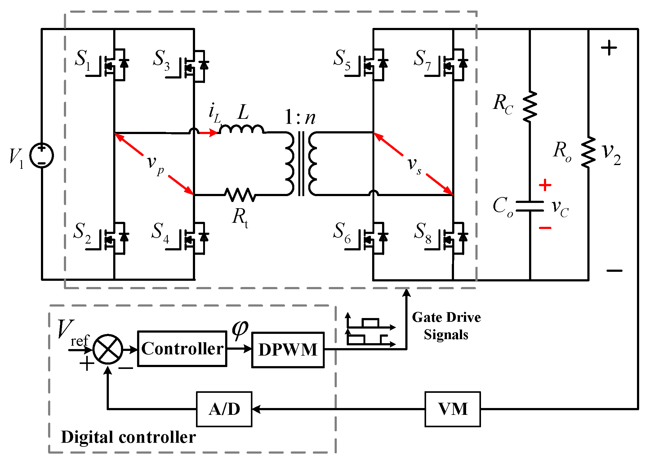
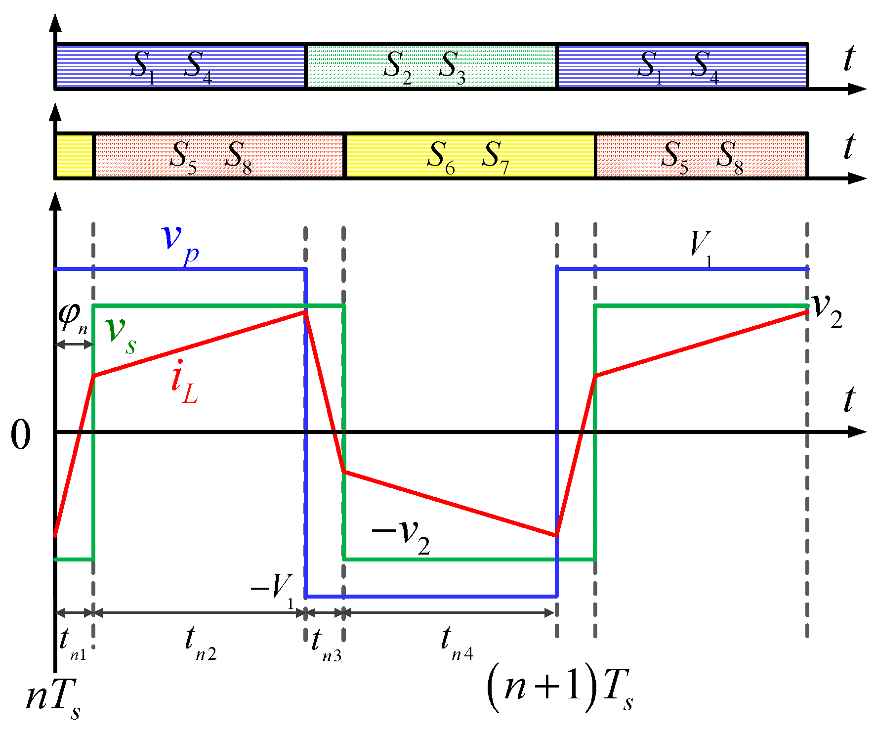
2. System Description

The digitally controlled DAB converter consists of the power stage and the digital controller, as shown in Figure 1. The power stage includes a high-frequency transformer and two H-bridges, enabling the bidirectional power flow. The two active bridges are interfaced through a high-frequency transformer operating at the fixed switching frequency fs, which provides the required galvanic isolation and the voltage matching between the two voltage buses with a turn ratio of 1:n. The transformer leakage inductance and the auxiliary inductance work as the main instantaneous energy transfer element. Rt is the sum of the line resistance, power switches on-resistance, and the transformer winding resistance. Co is the output capacitor and RC is the equivalent series resistance of the output capacitor. V1 and v 2 are the voltages of the two dc buses, respectively.
The single-phase-shift modulation method, which is suited for a higher power transfer and is easy to implement is applied in this paper. According to the operating principle of the single-phase-shift modulation, the cross-connected switch pairs in each bridge were controlled with the constant duty cycle (50%) to generate the high-frequency square-wave voltage v p and v s at the transformer terminals. Considering the leakage inductance of the transformer serves as an energy transfer element, the phase shift angle φ between v p and v s is selected as the control variable, which can be adjusted to ensure the two square waves appropriately phase-shifted to control the direction as well as the magnitude of the power flow. Since the power is delivered from the bridge, which generates the leading square wave, the positive phase shift angle φ is defined when the primary side v p is leading the secondary side v s . For example, the operating waveforms in the steady state when φ is positive are shown in Figure 2, with the power flowing from the V1-side to the v 2 -side accordingly. In addition, the converter exhibits four subintervals in one switching period, referred to by their corresponding timing labels from tn1 to tn4. Due to the symmetry of the power circuit, the state variables of the DAB converter are also symmetrical within a switching period.
The implementation of the corresponding digital controller is realized through the TMS320F28335 microcontroller of Texas Instruments. The output voltage v 2 and the current iL of the transformer leakage inductance are sampled and sent to the controller at the beginning of each switching period to calculate the phase shift angle φ . In addition, a saturator element controls the limit of the phase shift angle φ with the range from 0 to π/2. Accordingly, the two active bridges operate in a complementary way according to the phase shift angle φ .

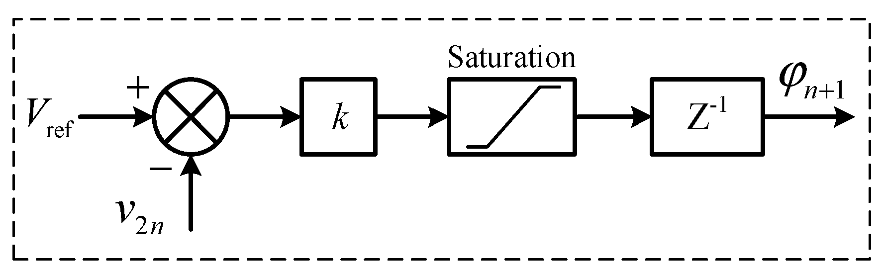
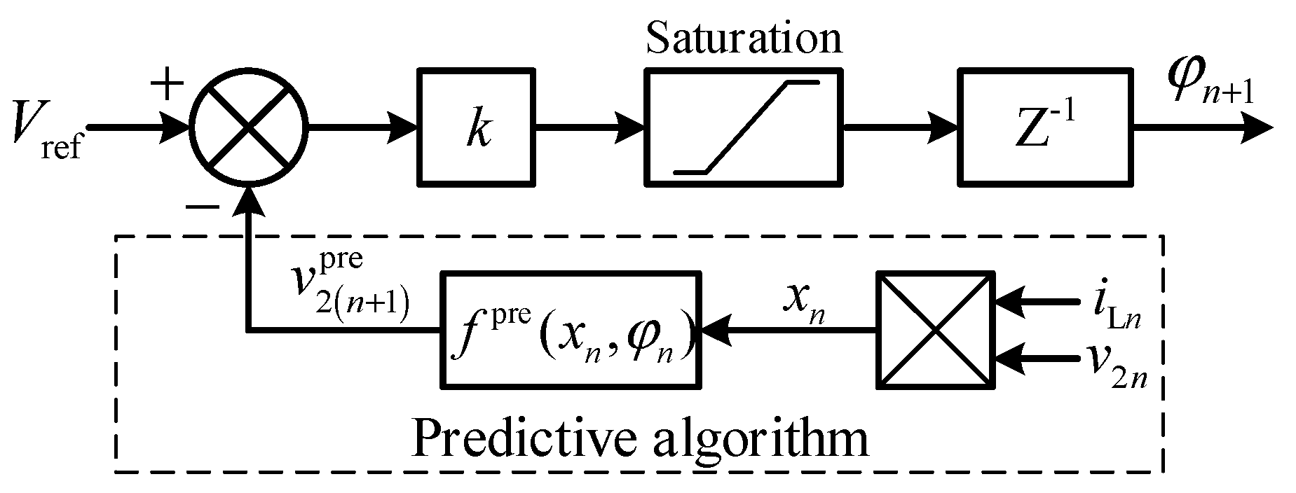
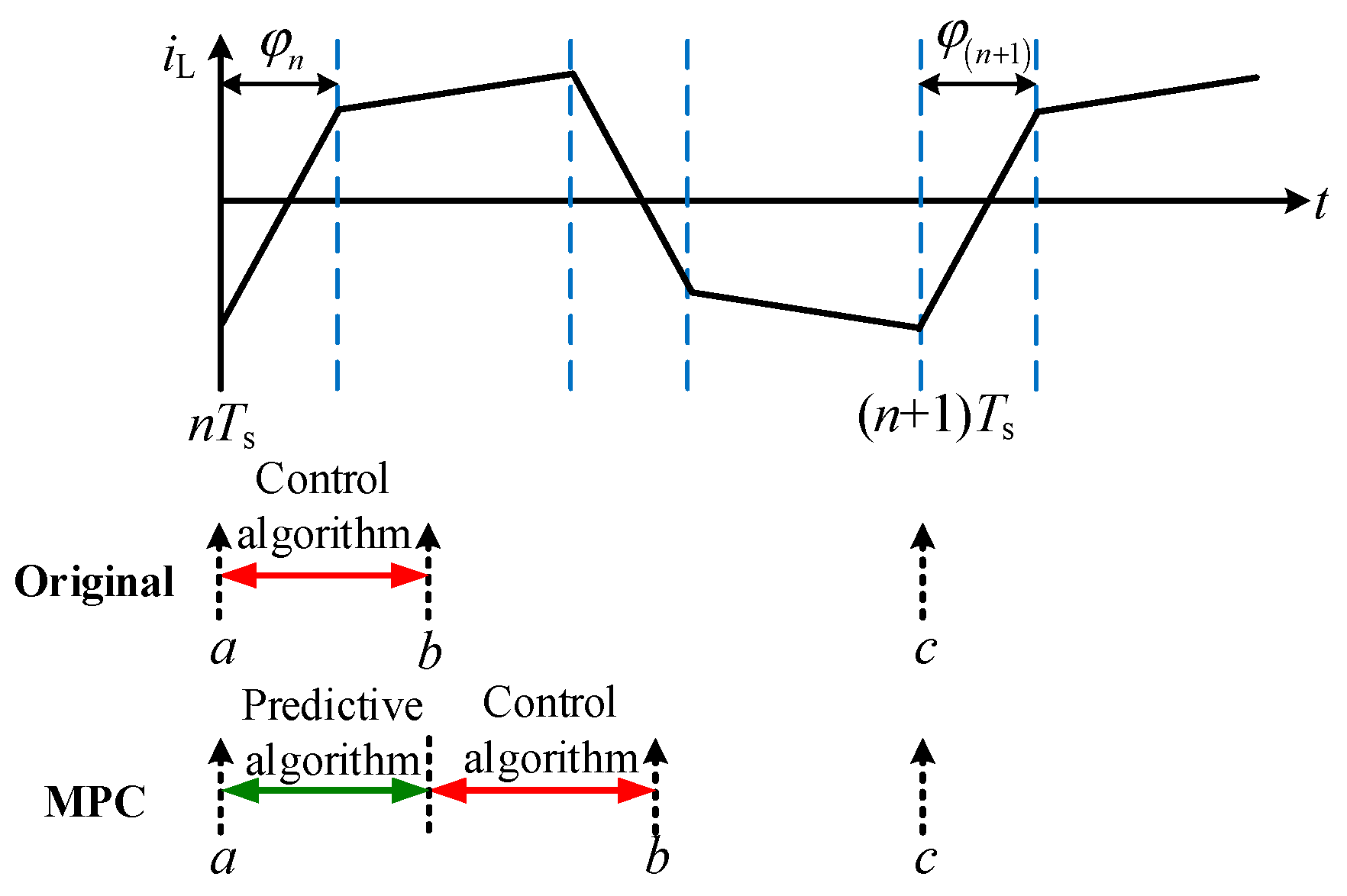
3. Model Predictive Control and Modeling

It is common that the one-step-delay control scheme is adopted in the digitally controlled power converters to avoid the minimum duty ratio limit caused by the digital control delay. However, the digital control delay could reduce the system performance and sometimes lead to the instability of the system. Therefore, the model predictive control based on the discrete-time iteration of the DAB converter is proposed in this section to deal with the effect of control delay on the digital control system.
The block diagram of the conventional one-step-delay digital controller is illustrated in Figure 3. The periodically sampled output voltage v 2 n at the starting moment t = nTs of the n th switching cycle is utilized to calculate the phase shift angle φ in the digital controller. However, the calculated phase shift angle of the nth period cannot been applied until the (n + 1)th period. In other words, the calculated phase shift angle of the nth switching period could only play a controlling role in the next switching period. Accordingly, the discrete-time model of the conventional digital controller of the DAB converter can be expressed as Equation (1), where the inevitable one-step control delay is embodied.
φ n + 1 = k ( V ref n v 2 n ) , φ n + 1 [ 0 , π / 2 ]
To eliminate the one-step delay effect, the discrete-time iteration-based model predictive control strategy of the DAB converter is proposed. The block diagram of the digital controller is shown as Figure 4, where the predictive algorithm is attached to the conventional controller to compensate the one-step delay effect. The state variables i L n and v C n as well as the phase shift angle φ n at the beginning of the nth switching cycle are utilized by the predictive algorithm to predict the state variables x n + 1 p r e at the beginning of the (n + 1)th switching cycle. Then, the predicted output voltage v 2 ( n + 1 ) pre can also be obtained. It is worth nothing that the output voltage v 2 n under the conventional one-step-delay control scheme is replaced by v 2 ( n + 1 ) pre under the model predictive control scheme, which means the digital control delay effect is compensated. Since the attached predictive algorithm is not related to the original control algorithm, the proposed method has a strong portability and can be applied to many digital controllers with the one-step delay.
In order to implement the model predictive algorithm, it is essential to obtain the discrete-time iteration relationship of the DAB converter. As shown in Figure 2, there are four subintervals within a switching cycle in the DAB converter under the single-phase-shift control. According to the power stage structure of the DAB converter as shown in Figure 1, the system matrices A i and vectors B i corresponding to the different subintervals are expressed as Equations (2) and (3), where represents the subinterval [33].
A 1 = A 4 = [ n 2 R t + R o R C / ( R o + R C ) n 2 L R o n L ( R o + R C ) R o n C o ( R o + R C ) 1 C o ( R o + R C ) ] A 2 = A 3 = [ n 2 R t + R o R C / ( R o + R C ) n 2 L R o n L ( R o + R C ) R o n C o ( R o + R C ) 1 C o ( R o + R C ) ]
B 1 = B 2 = [ 1 L 0 ] , B 3 = B 4 = [ 1 L 0 ]
Due to the existence of the equivalent series resistance R C of the output capacitor, the sampling output voltage v 2 n at the moment of t = n T s is relevant to both the capacitor voltage v C n and the inductor current i L n . When the turns ratio of the high-frequency transformer is 1 : 1 , the equivalent circuit of the power stage of the digitally controlled DAB converter at the time of t = n T s is shown as Figure 5. According to the KCL and KVL of the circuit, the relationship among the output voltage, inductance current, and the capacitor voltage can be expressed as Equations (4) and (5).
v 2 n = T r x n = [ R o R C R o + R C R o R o + R C ] [ i L n v C n ]
v C n = [ R C R o + R C R o ] [ i L n v 2 n ]
The process of the model predictive control strategy is illustrated in Figure 6. Arrow a represents the sampling moment and arrow b represents the calculation finishing moment when the predicted phase shift angle φ n + 1 of the next switching period is solved. Next, arrow c is the moment when the phase shift angle φ n + 1 is uploaded and controls the phase shift angle between the two H-bridges. Accordingly, the subsequent periods will repeat the same operating principle.
The states variables x = [ i L v C ] T and the output voltage v 2 at the beginning of the n th and ( n + 1 ) th switching cycles are denoted as x n = [ i L n v C n ] T , v 2 n , x ( n + 1 ) = [ i L ( n + 1 ) v C ( n + 1 ) ] T and v 2 ( n + 1 ) , respectively. At moment a of Figure 6, the inductor current i L n and the output voltage v 2 n are sampled to calculate the output capacitor voltage v C n according to Equation (5). Then, the predictive algorithm in Figure 6 can be obtained according to the discrete-time iteration relationship f t n i between the subintervals within a switching cycle [13]. Finally, the discrete-time iteration based model predictive algorithm is expressed as Equation (6), where the state variables v C n , i L n and the phase shift angle φ n of the nth switching period are utilized to express the predictive value x n + 1 pre . Besides, the kernel predictive functions G and H are shown in Equation (7).
x n + 1 pre = f ( x n , φ n ) = f t n 4 ( f t n 3 ( f t n 2 ( f t n 1 ( x n , φ n ) ) ) ) = G ( φ n ) x n + H ( φ n ) V 1
G ( φ n ) = e A 4 t n 4 e A 3 t n 3 e A 2 t n 2 e A 1 t n 1 , H ( φ n ) = e A 4 t n 4 e A 3 t n 3 e A 2 t n 2 ψ 1 + e A 4 t n 4 e A 3 t n 3 ψ 2 + e A 4 t n 4 ψ 3 + ψ 4 , t n 1 = t n 3 = φ n / ( 2 f s π ) , t n 2 = t n 4 = 1 / ( 2 f s ) φ n / ( 2 f s π ) , ψ i = 0 t n i e A i t B i d t = A i 1 ( e A i t n i I ) B i , i = 1 , 2 , 3 , 4
According to the predictive control algorithm of Figure 6, the predicted output voltage v 2 ( n + 1 ) pre can be expressed as Equation (8) based on the predicted state variable x n + 1 pre , where the matrix Tr is shown in Equation (4). The predicted value v 2 ( n + 1 ) pre is then used to calculate the phase shift angle φ n + 1 of the ( n + 1 ) th switching cycle, as shown in (9). Finally, the predicted phase shift angle φ n + 1 is uploaded at the moment of t = ( n + 1 ) T s and exerts its influence during the ( n + 1 ) th switching cycle. Therefore, the effect of the one-step digital control delay is correspondingly compensated.
v 2 ( n + 1 ) pre = T r ( G ( φ n ) x n + H ( φ n ) V 1 )
φ n + 1 = k ( v ref ( n + 1 ) v 2 ( n + 1 ) pre )

4. Stability Analysis of the MPC DAB Converter

Since the time delay of the digital controller could exert great influence on the system dynamics, the Jacobian matrix and Floquet multipliers [34] are employed in this section for the stability analysis of the digitally controlled DAB converter. The advantages of the proposed model predictive control compared with the original control method are verified and the instability mechanism of the DAB converter is also revealed. The sensitivity of the proposed model predictive control algorithm to the system parameters is analyzed. Besides, the system parameter spaces and the stability boundaries are obtained and compared.

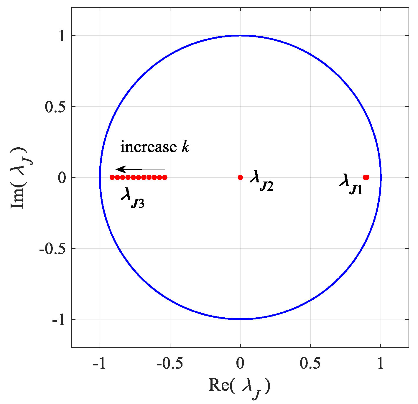
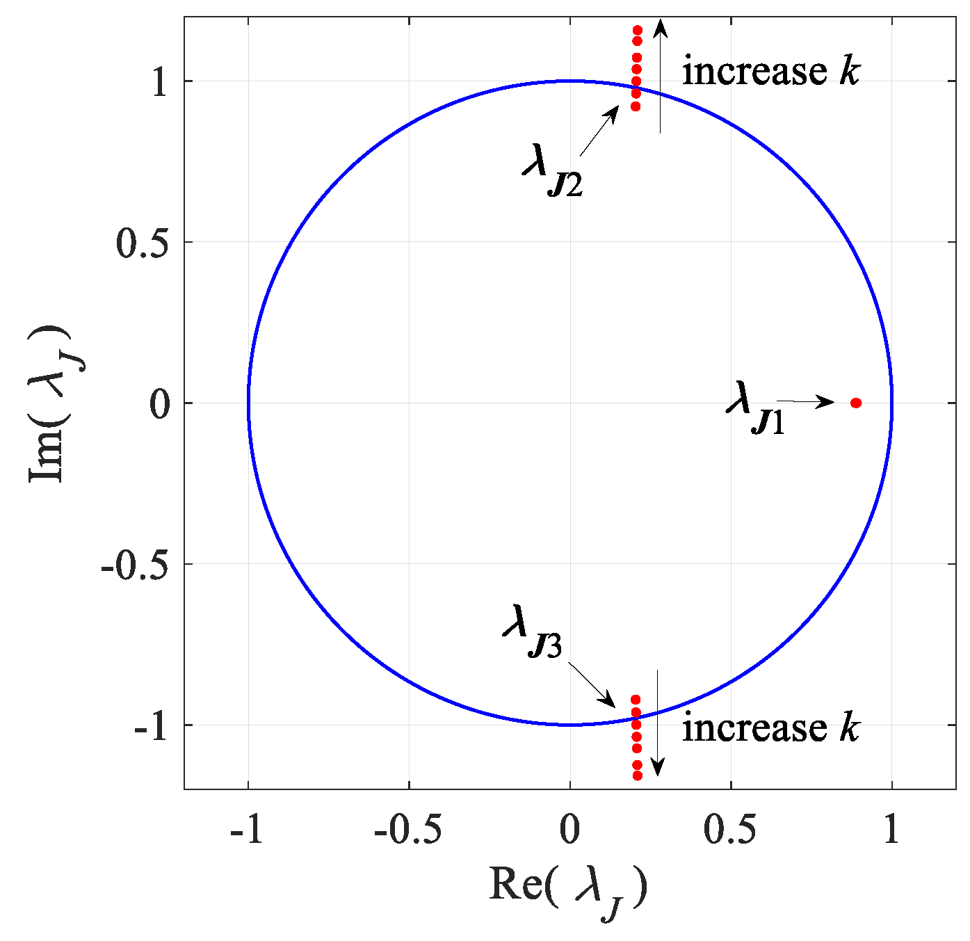
4.1. Calculation of Jacobian Matrix and Floquet Multipliers

The discrete-time model of the one-step delay controlled DAB converter is shown as Equation (10). The phase shift angle of the n th switching cycle is calculated according to the state variables of the n th switching cycle and can only play a controlling role in the ( n + 1 ) th switching cycle and therefore is rewritten as φ n + 1 .
{ i L ( n + 1 ) = [ 1 0 ] ( G ( φ n ) x n + H ( φ n ) V 1 ) v C ( n + 1 ) = [ 0 1 ] ( G ( φ n ) x n + H ( φ n ) V 1 ) φ n + 1 = k ( V ref n T r x n )
Compared with the discrete-time model of the conventional one-step delay controller described by Equation (1), the controller of the model predictive control DAB converter compensates for the digital control delay effect via the discrete-time iteration-based predictive algorithm as shown in Equation (9). Hence, the discrete-time model of the DAB converter based on the proposed model predictive control can be expressed as Equation (11), where x n + 1 pre = G ( φ n ) x n + H ( φ n ) V 1 .
{ i L ( n + 1 ) = [ 1 0 ] ( G ( φ n ) x n + H ( φ n ) V 1 ) v C ( n + 1 ) = [ 0 1 ] ( G ( φ n ) x n + H ( φ n ) V 1 ) φ n + 1 = k ( V ref ( n + 1 ) T r x n + 1 pre )
By taking the partial derivative of Equation (10) or (11), the Jacobian matrix of the digitally controlled DAB converter system can be calculated as shown in Equation (12). Then, the Floquet multipliers λ J 1 , λ J 2 and λ J 3 are obtained by solving the characteristic equation of Equation (13). The Floquet multipliers can be utilized to reveal the dynamic characteristics of the DAB converter. Besides, the different positions of the Floquet multipliers relative to the unit cycle correspond to the different dynamics of the DAB converter.
J ( I L , V C , Φ ) = [ i L ( n + 1 ) i L n i L ( n + 1 ) v C n i L ( n + 1 ) φ n v C ( n + 1 ) i L n v C ( n + 1 ) v C n v C ( n + 1 ) φ n φ ( n + 1 ) i L n φ ( n + 1 ) v C n φ ( n + 1 ) φ n ]
det ( λ I J ( I L , V C , Φ ) ) = 0
Since the stability analysis of the DAB converter requires the Jacobian matrix described in Equation (12) to be estimated at the steady state operating point ( X , Φ ) , it is essential to solve the steady state operating point first. Considering the symmetric characteristics of the state variables within a switching cycle, as shown in Figure 2, the steady state relationship between x n and x n 2 (the state variables at the end of the second subinterval) is expressed as Equation (14).
x n 2 = I Q x n = [ 1 0 0 1 ] x n
Meanwhile, the discrete-time iteration relationship between x n and x n 2 can be written as Equation (15) in light of the iterative process of the state variables within the first two subintervals of a switching cycle.
x n 2 = f t n 2 ( f t n 1 ( x n , φ n ) ) = e A 2 t n 2 ( e A 1 t n 1 x n + ψ 1 V 1 ) + ψ 2 V 1
The solution of the steady state operating point X = ( I L , V C ) can be obtained by considering Equations (14) and (15). Accordingly, the relationship between the steady steady X and phase shift angle Φ is expressed as Equation (16). Besides, we can also get the relationship between X and Φ as shown in Equation (17) according to the discrete-time model of the digital controller described by Equation (1). Finally, the steady state operating point ( I L , V C , Φ ) can be obtained by the simultaneous formulas (16) and (17), which are transcendental equations and can be solved by the Newton iteration method.
X = ( I Q e A 1 t n 1 e A 2 t n 2 ) 1 ( e A 2 t n 2 ψ 1 V 1 + ψ 2 V 1 )
Φ = k ( V ref T r X )

4.2. Stability Analysis via the Floquet Multipliers

The Floquet multipliers play an important role in the study of the dynamic characteristics of the DAB converter. Thus, the Floquet multipliers are employed for the stability analysis of the digitally controlled DAB converter in this part. After analyzing the Floquet multipliers of the corresponding periodic system, the stability and bifurcation types of the DAB converter system can be determined clearly. If there is at least one Floquet multiplier with the modulus greater than one, the system will enter the unstable state. The relative position of the unit cycle and the Floquet multipliers under the different system parameters has the deterministic influence on the system stability or on the way of losing stability. Then, the stable and unstable parameter spaces of the digitally controlled DAB converter can be obtained accordingly.
The system parameters of the DAB converter are shown in Table 1. Besides, the Floquet multipliers of the system can be solved according to Equation (13). When the conventional control strategy is adopted, the loci of the Floquet multipliers referred to the unit circle are shown in Figure 7 as the proportional coefficient k of controller increases from 0.3 to 0.7. It is obvious that the two conjugate Floquet multipliers vary with k, while the third one remains almost settled. When the two conjugate Floquet multipliers exceed the unit circle with the proportional coefficient k greater than 0.55, the system will exhibit a slow-frequency oscillation as shown in Figure 8b, which is also called the Hopf bifurcation. It is obvious that the inductor current with a much higher amplitude is not symmetrical within one switching period, which could result in the saturation of the transformer and a noise problem. The oscillation of the inductor current could also lead to an undesired voltage ripple of the DC bus. All of those will pose an extra impact on the devices’ stress, which is generally not wanted in practical applications.
Similarly, the loci of the Floquet multipliers are shown in Figure 9, when the proposed discrete-time iteration-based model predictive control is adopted with the same system parameters of Figure 7. It is remarkable that all the Floquet multipliers remain inside the unit cycle, which indicates the stable operation of the DAB converter. However, the inductor current already oscillates in the practical application under the conventional one-step delay control with the same control parameters, which indicates that the stable parameter spaces expand a lot when the proposed model predictive control is applied.

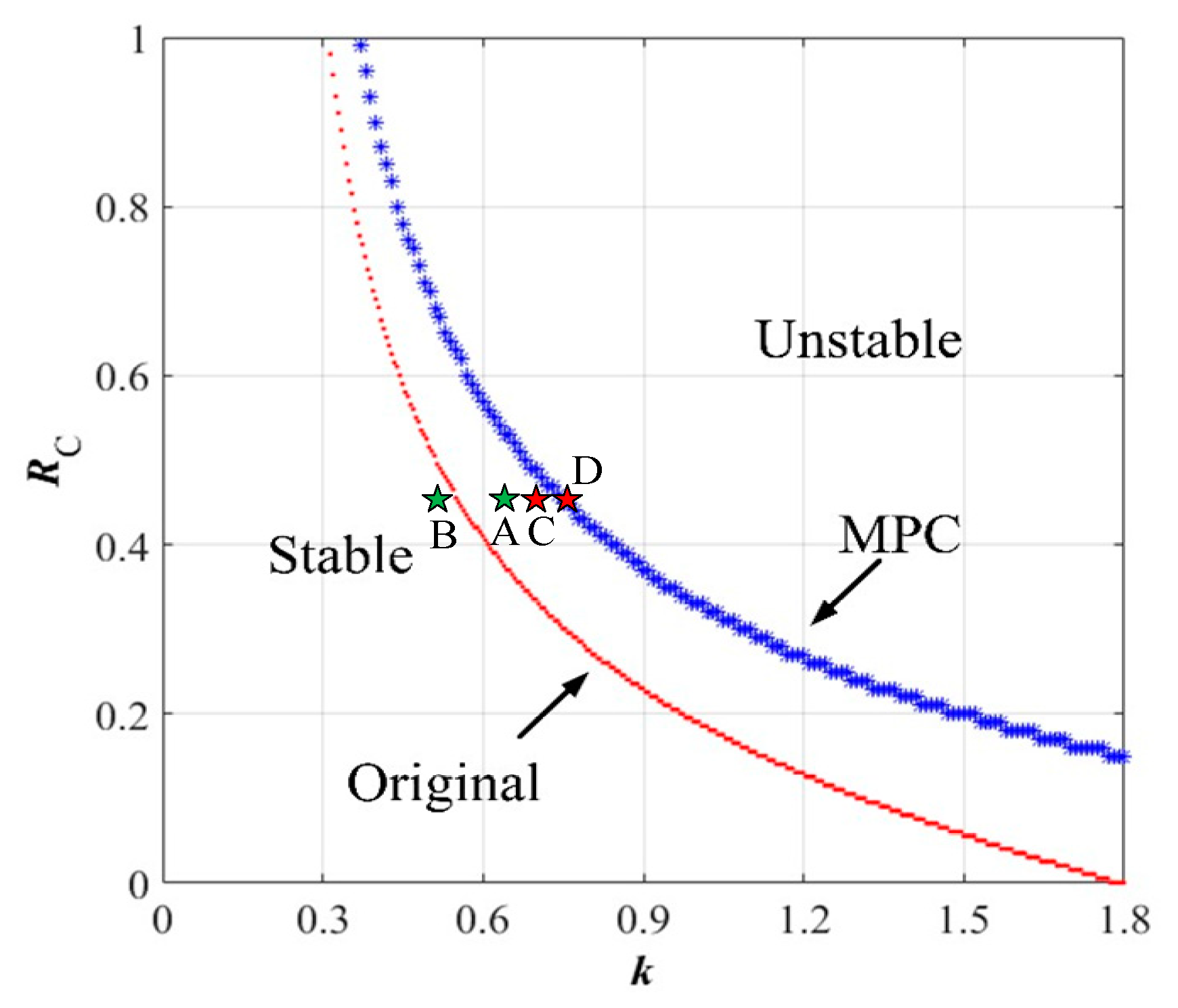
4.3. Stability Boundaries of the System

Since the equivalent series resistance RC of the output capacitor also has great influence on the stability of the digitally controlled DAB converter system [35], the RC and the proportional coefficient k of the controller are selected as the bifurcation parameters for the system stability boundaries’ analysis. The stability boundaries under the model predictive control and the original one-step delay control methods are illustrated in Figure 10. The red-dotted line represents the stability boundary of the original system and the blue star one is the stability boundary when the proposed model predictive control algorithm is employed. Besides, operating point A corresponds to the slow-frequency oscillation of Figure 8b and point B corresponds to the stable state of Figure 8a. Similarly, operating point C is related to the stable state of the DAB converter and point D corresponds to the stability boundary when the proposed model predictive control is applied. It can also be observed that if the proposed discrete-time iteration-based model predictive control method is adopted, the stable range of the system parameter space will extend significantly. In addition, the accurately predicted stability boundaries can be applied to the practical parameters design and guarantee the stable operation of the system.
In order to validate the effectiveness of the proposed discrete-time iteration-based model predictive control algorithm, simulation with and without the model predictive control is carried out. The proportional coefficient k = 0.65 and the original one-step delay controlled DAB converter system operate at point A according to Figure 10. As shown in Figure 11, when the predictive module is not working, the DAB converter is in the unstable state and the inductor current exhibits a low-frequency oscillation, which is consistent with the analysis of Figure 8b. After the predictive control module is activated at 0.2 s, the system converges to the stable state quickly, which is in accordance with the results of Figure 10.

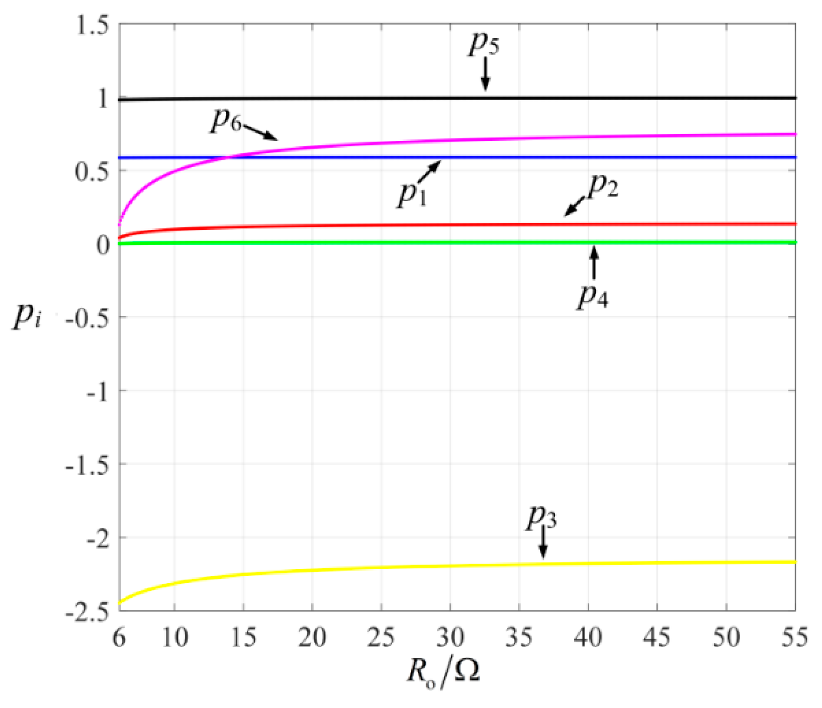
4.4. Sensitivity Analysis

In practical applications, the DAB converter is required to be applicable in a wide range of load changes. In order to indicate the sensitivity of the predictive algorithm to the different loads, the coefficients of the state variables in the predictive algorithm are extracted as p1p6 in Equation (18). The variation of p1p6 along with the variation of the load resistance is shown in Figure 12.
x n + 1 pre = G ( φ n ) x n + H ( φ n ) V 1   = [ p 1 p 2 p 3 p 4 p 5 p 6 ] [ i L n v C n φ n ]
It can be concluded from Figure 12 that the sensitivity of the coefficients to the variation of the load Ro is very low when Ro varies from 6 Ω to 55 Ω. The simulation results in Figure 13 also verify that the system remains in the stable state when the load Ro switches from 20 Ω to 6 Ω. It is obvious that the proposed model predictive control algorithm has a low sensitivity to the resistance of the load. In other words, the predictive algorithm in the digital controller does not need to be modified when the load changes, which is quite convenient in practical application, since the resistance of the load could frequently change in reality. Therefore, the proposed discrete-time iteration-based model predictive control method is compatible with a wide range of load conditions. The average or approximate value of the load can be utilized when the predictive algorithm is applied to practical applications.

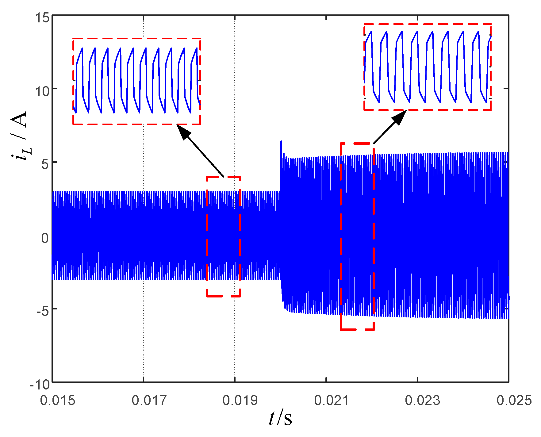
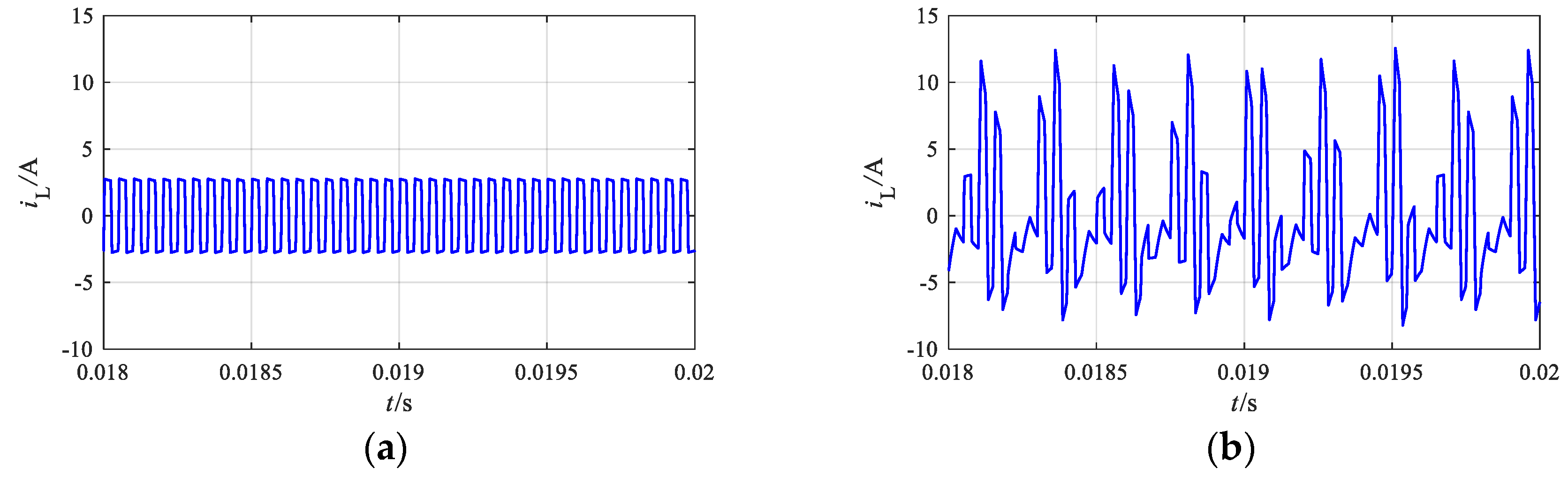
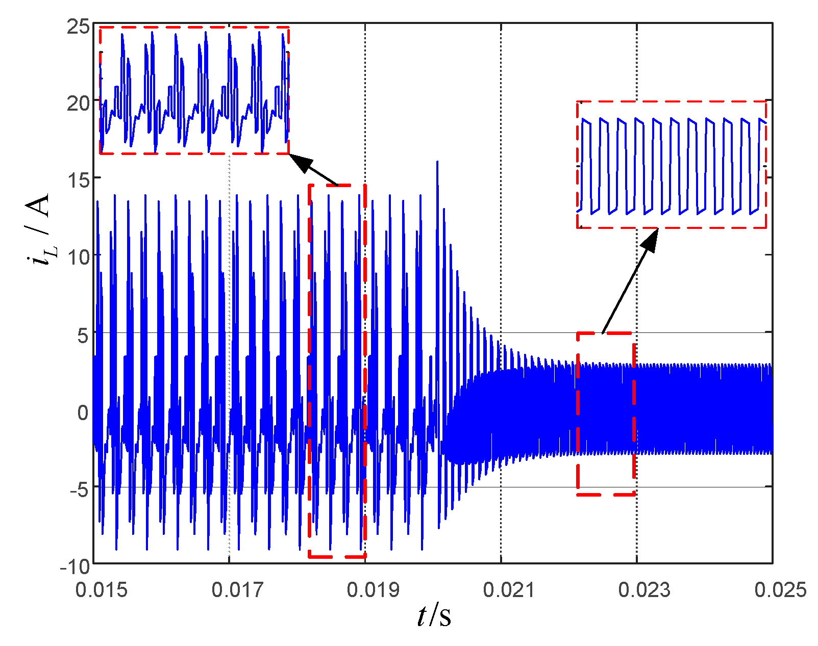
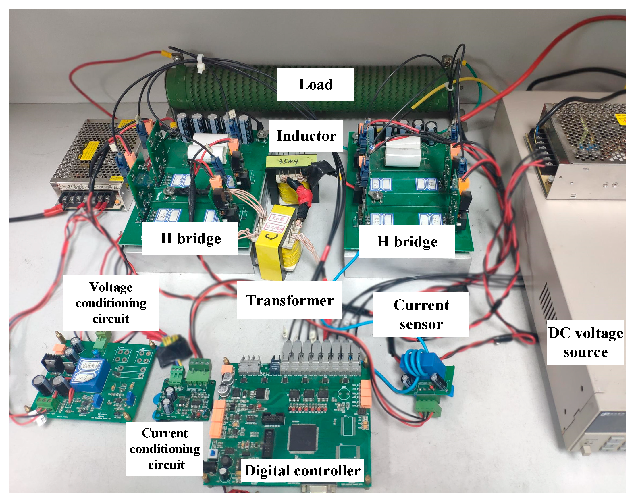
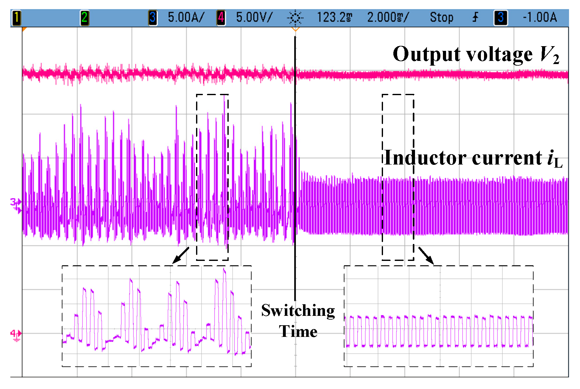
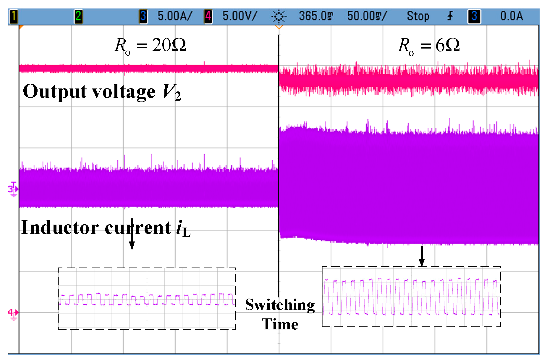
5. Experimental Verification

To verify the reliability and accuracy of the theoretical analysis, experiments were carried out. As shown in Figure 14, an experimental platform with the same design parameters as Table 1 was established to validate the numerical and simulation results. The inductor current of the DAB converter was measured by the current sensor and the current conditioning circuit. Besides, the output voltage was measured by the voltage conditioning circuit. Based on the measured state variable signals, the corresponding phase shift angle could be calculated in the TMS320F28335 microcontroller through the discrete-time model-based predictive algorithm.
When the proportional coefficient k is 0.65, the conventional one-step delay controlled DAB converter system will operate at the point A according to Figure 10. The waveforms of the state variables before and after enabling the predictive control module are shown in Figure 15. When the predictive module is not working, the DAB converter is unstable with the output voltage v2 and the inductor current iL exhibiting the low frequency oscillation, which is in accordance with the simulation results of Figure 8b and Figure 11. The asymmetrical inductor current with the high amplitude could saturate the transformer and pose undesirable impact on the power switches and other circuit components. Besides, the low frequency oscillation of the inductor current will inevitably lead to the noise of the transformer and the undesired ripple on the output DC bus. After the predictive control module is activated, the DAB converter quickly switches to the stable state, which is consistent with the simulation results of Figure 11.
In order to verify the previous sensitivity analysis, the experimental results with different load resistance are also shown in Figure 16, where the proportional coefficient is 0.65. It can be observed that when the load resistance Ro is switched from 20 Ω to 6 Ω, the system always remains in the stable state. Besides, the experimental waveforms of the state variables are in agreement with the simulation and analysis results of Figure 13.

6. Conclusions

In this paper, the modeling and stability analysis of the digitally controlled dual active bridge converter based on the model predictive control is investigated. The proposed discrete-time iteration-based model predictive control was utilized to eliminate the one-step delay effect of the digitally controlled DAB converter. Then, the discrete-time model of the MPC DAB converter system was obtained to conduct the stability analysis. Accordingly, the Jacobian matrix and Floquet multipliers were derived to reveal the mechanism of the complicated nonlinear dynamics of the MPC and conventional one-step delay controlled DAB converter for the first time. The phenomena and internal mechanism of the low-frequency Hopf oscillation were revealed. Besides, the analysis and the experimental results indicate that the proposed method is compatible with a wide range of load conditions and is able to increase the stable range of the system. Meanwhile, the obtained parameter space of the system can give good guidance for practical parameters’ design and guarantee the stable operation of the system.

Author Contributions

Conceptualization, G.G., L.S., and W.L.; methodology, G.G., L.S., and W.L.; software, G.G. and K.L.; validation, G.G., W.L., and Y.C.; data curation, Y.C.; writing—original draft preparation, Y.C. and S.Y.; supervision, W.L.; project administration, W.L.

Funding

This work was supported by the National Key Research & Development Plan, grant number 2018YFB0905800.

Conflicts of Interest

The authors declare no conflict of interest.

References

  1. Jang, S.-J.; Lee, T.-W.; Lee, W.-C.; Won, C.-Y. Bi-directional dc-dc converter for fuel cell generation system. In Proceedings of the 2004 IEEE 35th Annual Power Electronics Specialists Conference, Aachen, Germany, 20–25 June 2004; pp. 4722–4728. [Google Scholar]
  2. Profumo, F.; Tenconi, A.; Cerchio, M.; Bojoi, R.; Gianolio, G. Fuel cells for electric power generation: Peculiarities and dedicated solutions for power electronic conditioning systems. EPE J. 2006, 16, 44–51. [Google Scholar] [CrossRef]
  3. Samosir, A.S.; Yatim, A.H.M. Implementation of Dynamic Evolution Control of Bidirectional DC-DC Converter for Interfacing Ultracapacitor Energy Storage to Fuel-Cell System. IEEE Trans. Ind. Electron. 2010, 57, 3468–3473. [Google Scholar] [CrossRef]
  4. Engel, S.P.; Stieneker, M.; Soltau, N.; Rabiee, S.; Stagge, H.; De Doncker, R.W. Comparison of the Modular Multilevel DC Converter and the Dual-Active Bridge Converter for Power Conversion in HVDC and MVDC Grids. IEEE Trans. Power Electron. 2015, 30, 124–137. [Google Scholar] [CrossRef]
  5. Kim, J.; Kim, H.; Cho, J.; Cho, Y. High-Efficiency Bi-Directional Single-Phase AC/DC Converter Design and Field Application for LVDC Distribution. Energies 2019, 12, 2191. [Google Scholar] [CrossRef]
  6. Moonem, M.A.; Krishnaswami, H. Analysis of dual active bridge based power electronic transformer as a three-phase inverter. In Proceedings of the IECON 2012 38th Annual Conference on IEEE Industrial Electronics Society, Montreal, QC, Canada, 25–28 October 2012; pp. 238–243. [Google Scholar]
  7. Zhao, B.; Song, Q.; Liu, W.H.; Sun, Y.D. Overview of Dual-Active-Bridge Isolated Bidirectional DC-DC Converter for High-Frequency-Link Power-Conversion System. IEEE Trans. Power Electron. 2014, 29, 4091–4106. [Google Scholar] [CrossRef]
  8. Takagi, K.; Fujita, H. Dynamic Control and Performance of a Dual-Active-Bridge DC-DC Converter. IEEE Trans. Power Electron. 2018, 33, 7858–7866. [Google Scholar] [CrossRef]
  9. Feng, B.; Wang, Y.; Man, J. A novel dual-phase-shift control strategy for dual-active-bridge DC-DC converter. In Proceedings of the IECON 2014—40th Annual Conference of the IEEE Industrial Electronics SocietyIndustrial Electronics Society, Dallas, TX, USA, 29 October–1 Novmber 2014; pp. 4140–4145. [Google Scholar]
  10. Oggier, G.G.; Garcia, G.O.; Oliva, A.R. Switching Control Strategy to Minimize Dual Active Bridge Converter Losses. IEEE Trans. Power Electron. 2009, 24, 1826–1838. [Google Scholar] [CrossRef]
  11. Rodriguez, A.; Vazquez, A.; Lamar, D.G.; Hernando, M.M.; Sebastian, J. Different Purpose Design Strategies and Techniques to Improve the Performance of a Dual Active Bridge With Phase-Shift Control. IEEE Trans. Power Electron. 2015, 30, 790–804. [Google Scholar] [CrossRef]
  12. Oggier, G.G.; Garcia, G.O.; Oliva, A.R. Modulation Strategy to Operate the Dual Active Bridge DC-DC Converter Under Soft Switching in the Whole Operating Range. IEEE Trans. Power Electron. 2011, 26, 1228–1236. [Google Scholar] [CrossRef]
  13. Krismer, F.; Kolar, J.W. Accurate Small-Signal Model for the Digital Control of an Automotive Bidirectional Dual Active Bridge. IEEE Trans. Power Electron. 2009, 24, 2756–2768. [Google Scholar] [CrossRef]
  14. Buccella, C.; Cecati, C.; Latafat, H. Digital control of power converters—A survey. IEEE Trans. Ind. Inform. 2012, 8, 437–447. [Google Scholar] [CrossRef]
  15. Liu, Y.-F.; Meyer, E.; Liu, X. Recent developments in digital control strategies for DC/DC switching power converters. IEEE Trans. Power Electron. 2009, 24, 2567–2577. [Google Scholar]
  16. Aguilera, R.P.; Acuna, P.; Konstantinou, G.; Vazquez, S.; Leon, J.I. Basic Control Principles in Power Electronics: Analog and Digital Control Design. In Control of Power Electronic Converters and Systems; Elsevier: Amsterdam, The Netherlands, 2018; pp. 31–68. [Google Scholar]
  17. Maksimovic, D.; Zane, R.; Erickson, R. Impact of digital control in power electronics. In Proceedings of the the 16th International Symposium on Power Semiconductor Devices & Ics (ISPSD ’04), Kitakyushu, Japan, 24–27 May 2004; pp. 13–22. [Google Scholar]
  18. Lu, M.H.; Wang, X.F.; Loh, P.C.; Blaabjerg, F.; Dragicevic, T. Graphical Evaluation of Time-Delay Compensation Techniques for Digitally Controlled Converters. IEEE Trans. Power Electron. 2018, 33, 2601–2614. [Google Scholar] [CrossRef]
  19. Debbat, M.B.; El Aroudi, A.; Giral, R.; Martinez-Salamero, L. Stability analysis and bifurcations of SEPIC DC-DC converter using a discrete-time model. In Proceedings of the 2002 IEEE International Conference on Industrial Technology (ICIT’ 02), Vols I and Ii, Bankok, Thailand, 11–14 December 2002; pp. 1055–1060. [Google Scholar]
  20. Yu, D.S.; Iu, H.H.C.; Chen, H.; Rodriguez, E.; Alarcon, E.; El Aroudi, A. Instabilities in Digitally Controlled Voltage-Mode Synchronous Buck Converter. Int. J. Bifurc. Chaos 2012, 22, 1250012. [Google Scholar] [CrossRef]
  21. Shankar, D.P.; Govindarajan, U.; Karunakaran, K. Period-bubbling and mode-locking instabilities in a full-bridge DC-AC buck inverter. IET Power Electron. 2013, 6, 1956–1970. [Google Scholar] [CrossRef]
  22. Xiong, X.L.; Tse, C.K.; Ruan, X.B. Bifurcation Analysis of Standalone Photovoltaic-Battery Hybrid Power System. IEEE Trans. Circuits Syst. I 2013, 60, 1354–1365. [Google Scholar] [CrossRef]
  23. Vazquez, S.; Leon, J.I.; Franquelo, L.G.; Rodriguez, J.; Young, H.A.; Marquez, A.; Zanchetta, P. Model Predictive Control A Review of Its Applications in Power Electronics. IEEE Ind. Electron. Mag. 2014, 8, 16–31. [Google Scholar] [CrossRef]
  24. Kouro, S.; Perez, M.A.; Rodriguez, J.; Llor, A.M.; Young, H.A. Model Predictive Control MPC’s Role in the Evolution of Power Electronics. IEEE Ind. Electron. Mag. 2015, 9, 8–21. [Google Scholar] [CrossRef]
  25. Cortes, P.; Kazmierkowski, M.P.; Kennel, R.M.; Quevedo, D.E.; Rodriguez, J. Predictive Control in Power Electronics and Drives. IEEE Trans. Ind. Electron. 2008, 55, 4312–4324. [Google Scholar] [CrossRef]
  26. Bakeer, A.; Ismeil, M.A.; Orabi, M. Modified finite control set-model predictive controller (MFCS-MPC) for quasi Z-source inverters based on a current observer. J. Power Electron. 2017, 17, 610–620. [Google Scholar] [CrossRef]
  27. Pawar, D.N.; Singh, N.M. MPC based controller for dual active bidirectional DC-DC converter driving inverter using dynamic phasor approach. In Proceedings of the 2017 IEEE International Conference on Power, Control, Signals and Instrumentation Engineering (ICPCSI), Chennai, India, 21–22 September 2017; pp. 661–666. [Google Scholar]
  28. An, F.; Song, W.; Yang, K.; Hou, N.; Ma, J. Improved dynamic performance of dual active bridge dc–dc converters using MPC scheme. IET Power Electron. 2018, 11, 1756–1765. [Google Scholar] [CrossRef]
  29. Wen, H.Q. Determination of the Optimal Sub-mode for Bidirectional Dual-Active-Bridge DC-DC Converter with Multi-Phase-Shift Control. In Proceedings of the 2013 IEEE ECCE Asia Downunder (ECCE Asia), Melbourne, Australia, 3–6 June 2013; pp. 596–600. [Google Scholar]
  30. Tariq, M.; Maswood, A.I.; Gajanayake, C.J.; Gupta, A.K.; Sasongko, F. Battery Energy Storage System Integration to the More Electric Aircraft 270 V DC Power Distribution Bus using Peak Current Controlled Dual Active Bridge Converter. In Proceedings of the 2017 IEEE Energy Conversion Congress and Exposition (ECCE), Cincinnati, OH, USA, 1–5 October 2017; pp. 2068–2073. [Google Scholar]
  31. Wu, K.Y.; de Silva, C.W.; Dunford, W.G. Stability Analysis of Isolated Bidirectional Dual Active Full-Bridge DC-DC Converter With Triple Phase-Shift Control. IEEE Trans. Power Electron. 2012, 27, 2007–2017. [Google Scholar] [CrossRef]
  32. Shi, L.; Lei, W.J.; Li, Z.Q.; Huang, J.; Cui, Y.; Wang, Y. Bilinear Discrete-Time Modeling and Stability Analysis of the Digitally Controlled Dual Active Bridge Converter. IEEE Trans. Power Electron. 2017, 32, 8787–8799. [Google Scholar] [CrossRef]
  33. Costinett, D.; Zane, R.; Maksimović, D. Discrete-time small-signal modeling of a 1 MHz efficiency-optimized dual active bridge converter with varying load. In Proceedings of the 2012 IEEE 13th Workshop on Control and Modeling for Power Electronics (COMPEL), Kyoto, Japan, 10–13 June 2012; pp. 1–7. [Google Scholar]
  34. Mazumder, S.; Alfayyoummi, M.; Nayfeh, A.H.; Borojevic, D. A theoretical and experimental investigation of the nonlinear dynamics of DC-DC converters. In Proceedings of the 2000 IEEE 31st Annual Power Electronics Specialists Conference. Conference Proceedings (Cat. No.00CH37018), Galway, Ireland, 23 June 2000; Volume 2, pp. 729–734. [Google Scholar]
  35. Shi, L.; Lei, W.J.; Huang, J.; Li, Z.Q.; Cui, Y.; Wang, Y. Full Discrete-Time Modeling and Stability Analysis of the Digital Controlled Dual Active Bridge Converter. In Proceedings of the 2016 IEEE 8th International Power Electronics and Motion Control Conference (IPEMC-ECCE Asia), Hefei, China, 22–26 May 2016. [Google Scholar]
Figure 1. Diagram of the digitally controlled DAB converter.
Energies 12 03103 g001
Figure 2. Operation waveforms in the steady state.
Energies 12 03103 g002
Figure 3. Block diagram of the one-step delay digital controller.
Energies 12 03103 g003
Figure 4. Block diagram of the model predictive control digital controller.
Energies 12 03103 g004
Figure 5. Equivalent circuit of the power stage of the DAB converter at the moment of t = nTs.
Energies 12 03103 g005
Figure 6. Model predictive control strategy of the DAB converter.
Energies 12 03103 g006
Figure 7. The loci of the Floquet multipliers under the conventional one-step delay control.
Energies 12 03103 g007
Figure 8. Waveforms of the inductor current. (a) Before the Hopf bifurcation (k = 0.5); (b) after the Hopf bifurcation (k = 0.65).
Energies 12 03103 g008
Figure 9. The loci of the Floquet multipliers under the model predictive control.
Energies 12 03103 g009
Figure 10. The parameter space under the different control schemes.
Energies 12 03103 g010
Figure 11. Inductor current before and after activating the predictive module.
Energies 12 03103 g011
Figure 12. Sensitivity of the predictive algorithm coefficients to the load change.
Energies 12 03103 g012
Figure 13. The inductor current under different load resistance.
Energies 12 03103 g013
Figure 14. Experimental platform.
Energies 12 03103 g014
Figure 15. The state variables before and after activating the predictive algorithm.
Energies 12 03103 g015
Figure 16. State variables under the model predictive control with the load change when k = 0.65.
Energies 12 03103 g016
Table 1. System parameters of the DAB converter.
ParametersValueParametersValue
V130 VRo12.5 Ω
L35.49 μHfs20 kHz
Rt0.38 Ωn1
Co455 μFVref30 V
RC0.45 Ωk0.1–0.65

