Article

On the Melting Process of the Phase Change Material in Horizontal Rectangular Enclosures

1
Department of Mechanics, Huazhong University of Science and Technology, Wuhan 430074, China
2
Hubei Key Laboratory of Engineering Structural Analysis and Safety Assessment, Luoyu Road 1037, Wuhan 430074, China
3
School of Naval Architecture and Ocean Engineering, Huazhong University of Science and Technology, Wuhan 430074, China
*
Author to whom correspondence should be addressed.
Energies 2019, 12(16), 3100; https://doi.org/10.3390/en12163100
Submission received: 10 July 2019 / Revised: 9 August 2019 / Accepted: 10 August 2019 / Published: 12 August 2019
(This article belongs to the Section J: Thermal Management)

Abstract

:
Phase change material (PCM) is one of the most important ways to store and manage energy. The melting process of PCM in a rectangular enclosure with the different aspect ratio is frequently related to some thermal energy storage devices. In this work, the melting of PCM in the horizontal rectangular enclosures heated from the different sides and the influence of aspect ratio of the rectangle are carefully studied. The enthalpy porosity technique and the finite volume method (FVM) are used to simulate the melting process numerically. The results show that the melting process of PCM can be dominated by conduction or natural convection due to the different heated sides. The melting of PCM in the enclosure heated from the bottom side is firstly affected by conduction and then mostly influenced by convection. In addition, the aspect ratio of the rectangular enclosure is found to play an important role in the melting process. Finally, a series of fitting correlations of the liquid fraction, Nusselt number and the energy storage are presented with the influence of aspect ratios in order to provide the reference for designing the rectangular container of PCM. This study is helpful for the selection of an appropriate aspect ratio and heating method to achieve the desired energy storage performance of encapsulated PCM.

1. Introduction

Phase change material (PCM) can absorb and release a large amount of latent heat during the melting or solidification process. It is therefore widely used in energy storage devices, such as the photovoltaic (PV) devices [1,2], domestic buildings [3], waste heat recovery [4], and the thermal management of battery [5], as well as the garment [6]. In these applications, it is crucial to fulfilling the energy storage and management in a short time because PCM is widely applied in time-dependent environments, such as the harvest of intermittent solar and wind energy, the charging and discharging processes of lithium-ion batteries of electric vehicles, and so on. Therefore, there is a persistent demand on the understanding of heat transfer and melting rate for the PCM to improve its thermal management ability and satisfy its diversity application.
The rectangular enclosure is the most common container of thermal energy storage devices. For instance, the rectangular heatsink was used for PV [7,8], the rectangular collector device was used for solar power [9], and PCM filled in the rectangular containers integrated into the building constructs was used to store or release the thermal energy [10,11]. Due to the low heat conductivity of PCMs especially for nonmetallic PCM, many researchers presented useful technologies to improve the melting rate when the PCMs were melting in the rectangular cavities. For instance, an inverted technique to change the direction of gravitational acceleration [12] and lots of pin fins to expand the heat transfer area of the cavity [13] are proposed to enhance the melting rate of PCM in a rectangular enclosure. Indeed, among these methods of enhancing the melting rate of PCM, increasing the heat transfer area is an effective method [14,15,16]. Beyond that, adding the nanoparticle into phase change material in the rectangular cavities can also improve the melting rate of PCM effectively [17,18].
Most researchers focus on improving the low thermal conductivity of PCM to enhance melting rates. On the other hand, the geometrical characteristic of containers also influences the melting rate of pure PCM [19]. In Kamkari et al. [20] and Zhao et al. [21], a series of experiments and simulations were performed to study the influence of tilt angle of PCM enclosures on melting by heating different sides. It can be found that the inclined angle of containers could affect the melting rate of PCM greatly. Moreover, the aspect ratio of the rectangular enclosure also has a contribution to the melting rate of PCM [22,23,24]. Besides the influence of orientation and aspect ratio of containers, heating the different sides of the rectangular enclosure also plays an important role in the melting process of PCM. For instance, by using a heat flow meter apparatus, Fantucci et al. [25] have measured a significant change of equivalent thermal conductivity of the PCM between the upper and the below-heated samples. The difference was mainly attributed to the convection occurring in the below-heated sample. Therefore, it is necessary to study the influence of heated side for PCM melting in the rectangular containers. Because of the influence of natural convection, different heated sides could acquire different melting rate of PCM [26,27,28,29]. Konig-Haagen et al. numerically studied the melting of PCM with the influence of natural convection in a rectangular cavity with five different solvers by heating the lateral side [30]. They had shown that the approach formulated in terms of enthalpy appear to be more robust than the other using temperature formulations. Hence, the enthalpy-porosity method is adopted in this study.
Although the influence of the aspect ratio of the rectangular enclosure and the heated sides on melting rate are well identified in the previous studies, these influence factors are more emphasized on the qualitative behavior. How to guide the engineer to design a suitable enclosure is still indistinct. Therefore, the first part of this paper is devoted to answering: How to design the rectangular cavity to achieve the highest melting rate of pure PCM with same thermal storage capacity through heating one side of the cavity. Therefore, heating from the top, right, and bottom side and the setting of different aspect ratios are discussed in detail. The second part of this paper is devoted to achieving the dimensionless scaling law or empirical relation for such a melting process in a rectangular enclosure with different aspect ratios. The proposed fitting correlations could predict the liquid fraction, Nusselt number, and the dimensionless specific enthalpy versus dimensionless time with the influence of aspect ratio and heated side. This study provides a fundamental understanding of the melting process of PCM with heating the different sides, and significant references for designing the rectangular container of PCM.
This paper is organized as follows. In Section 2, the mathematical formulations and numerical methods, as well as numerical validations, are presented. In Section 3, the numerical results of three different aspect ratios heated by different sides are reported to illustrate the influence of aspect ratio for the different heated side. Then the results with more different aspect ratios are presented in the original unit to exhibit the melting rate with different settings. The analysis and correlation fitting in the non-dimensional form are presented in Section 4, followed by a concluding remark in Section 5.

2. Mathematical Formulation and Numerical Validation

2.1. Problem Statement

In this study, a rectangular thermal storage enclosure, as shown in Figure 1 with the same cross-sectional area A = H·W was considered, which suggests the thermal storage capacity is fixed. When only one side is allowed to be heated, then the width (W) and the height (H) or the aspect ratio (AR = H/W) of the cavity would be crucial to the melting rate of PCM inside. At the beginning (t = 0), the temperature of PCM is supposed to be ambient temperature T0, which is assumed to less than the melting temperature of PCM (T0 < Tm). Consequently, PCM is solid inside the enclosure at the beginning. To study the geometrical influence on the melting behavior in the cavity, one side of the cavity was set as a hot wall with Tw > Tm. The direction of gravitational acceleration is supposed to be along the opposite direction of the y-axis.
In this work, the two-dimensional simulations are performed by the assumption flow, is the same in a long enough cavity. The cross-sectional area is set as 100 mm2, which is suitable for many applications for the thermal management of electrical devices, special garments, and so on.

2.2. Mathematical Formulation

In order to predict phase-change behavior and track the motion of solid-liquid front, the well-known enthalpy-porosity method [31] is adopted. The enthalpy-porosity method is one of the most widely applied to simulate the present mixture solid-liquid problem. In this method, the volume modification arisen by the phase change is ignored. In every controlled volume, the porosity is dependent on its liquid fraction. One of the advantages of this method is that the tracking of the PCM melting front is avoided. In the present two-dimensional system, the continuity and the momentum equations can be written as follow:
u x + v y = 0
ρ u t + ρ u u x + ρ v u y = p x + μ 2 u x 2 + μ 2 u y 2 + S u
ρ v t + ρ u v x + ρ v v y = p y + μ 2 v x 2 + μ 2 v y 2 + ρ g + S v
In Equation (3), the density in the buoyancy force term conforms to the Boussinesq approximation, which can be considered to be a function of the temperature. The reference density of this paper is the density of liquid PCM. The parameter S in Equations (2) and (3) is the porosity function defined by Brent et al. [31]. The terms are added to the momentum equations due to the effect of phase change on convection.
S = C ( 1 γ ) 2 γ 3 + ε
where C is the mushy zone constant. In the very limited mushy zone, the mushy zone constant is important to specific PCM, which is desirably in the range of 105–108 in most of the studies on the phase change of PCM [32]. In this paper, the C is set to 105. Different mushy zone constants have been tested (C = 105–107) and the results were almost identical. In Equation (4), ε is a small number used to avoid division by zero, whose value is 0.001; and γ is the liquid fraction of a cell, which is expressed as follows:
γ = { 0 i f T T s T T s T l T s i f T l < T < T s 1 i f T T l
The energy equation of PCM can be expressed as follows [31]:
ρ h t + ρ ( u h ) x + ρ ( v h ) y = x ( k T x ) + y ( k T y )
The above problem allows us to define the non-dimensional parameters related to the present study. Except for the above-defined aspect ratio, there is Rayleigh number (Ra), Prandtl number (Pr) and Nusselt number (Nu), as well as the dimensionless time (θ) obtained by the product of Stefan number (Ste) and Fourier number (Fo), could be related. And the dimensionless specific enthalpy (E) is also defined. They are well defined as the following forms [33]:
Ra = g ρ β H 3 ( T w T s ) α μ
Pr = μ ρ α
θ = S t e Fo = c p ( T w T s ) h s f α t H 2
Nu = Q k ( T w T m )
E = e h s f
where α = k c p ρ is the thermal diffusivity coefficient, Q is the instantaneous total heat transfer rate per unit length through the isothermal wall, and e represents the specific enthalpy per unit mass of PCM. It is noted that the real height of the cavity (H) is not necessary, then an effective Rayleigh number, which is the average heights of the melting of PCM for the bottom heated case could be defined by replacing H. In this study, Rayleigh numbers are less than 7 × 10⁵ and the Prandtl number is set to 6.722.

2.3. Initial and Boundary Conditions

To make the above partial differential system well-posed, the initial and boundary conditions should be well-defined. At the beginning (t = 0), the fluid velocity is set to zero and the initial temperature of PCM is 270 K. All of the boundary walls are no-slip i.e., u = v = 0. Except for the temperature of the heated wall being 343.15 K, the rest walls adopt the adiabatic condition. Furthermore, the liquid is supposed to be Newtonian and incompressible. The flow is laminar flow.

2.4. Numerical Method

In this work, the finite volume method (FVM) is used to solve the above governing equations by the commercial CFD package, ANSYS Fluent 17.1. The discrete form of above conservational equations is solved by the SIMPLE (semi-implicit method for pressure-linked equations) algorithm in order to couple the velocity and pressure field. The convective terms of momentum and energy equations are discretized by the second-order upwind scheme. The under-relaxation factors for pressure, density, momentum, and liquid fraction update are 0.3, 1.0, 0.2, and 0.9, respectively. The convergence of the solution is checked at each time step with the criterion that the scaled residuals are less than 10−3 for the continuity equation, 10−4 for the momentum equation, and 10−8 for the energy equation.

2.5. Numerical Verification and Validation

In fact, the porosity enthalpy technology will only exhibit the first-order accuracy near the interface of the solid and liquid zone even though the second-order is adopted [34]. Then the cell number of the computational domain is quite important to obtain a grid-independent solution. In this work, non-uniform quadrilateral cells are generated for all cases. Figure 2 and Figure 3 show the verification of convergence by using different cell numbers and time-step sizes for AR = 1 when the bottom side, right side, and the top side are heated, respectively. The tested cell number including 10,000, 12,321, and 15,625. In Figure 2, it can be seen that further refinement of the grid size only changed the solution a little. Therefore, the cell number of 12,321 and the time step size of 0.1 s could satisfy the calculation accuracy for such a low Rayleigh number problem.
Furthermore, the present results are compared to other previous studies to verify the present results were reliable. The parameters of PCMs adopted for numerical validation and simulation are shown in Table 1. Their thermophysical properties listed are based on the references [35,36,37]. The numerical validation is based on the comparison with both the numerical [35] and experimental results [36,37]. The gravitational acceleration is 9.81 m/s2 and vertically downward for all of the comparing cases.
In Figure 4, the comparison is made with the previous numerical study on the PCM of pure tin with the initial temperature of 505 K [35]. The temperatures of the left and right wall are 508 K and 505 K, respectively. The horizontal walls are thermally insulated. Figure 4a shows the trace of the melting front and Figure 4b shows the evolution of the liquid fraction in the cavity. The simulation results are in a good agreement with the results in reference. In Figure 5, the PCM in experiments is pure n-octadecane with the initial temperature 298.15 K. The horizontal walls are adiabatic. The temperatures of the left and right walls are 301.15 K and 298.15 K, respectively. The simulation results of the melting front in Figure 5a also show a consistent trend with the experimental observation. Furthermore, the liquid fraction is also in good agreement with previous experimental results (Figure 5b). The trivial discrepancy of the melting front from 2 h may arise possibly by the difference between the three-dimensional experiment and present a two-dimensional simulation. In the three-dimensional experiment, the melting front would not be consistent because the ending wall of the cavity may produce the secondary flow phenomenon by the effect of fluid viscosity. As the melting front advances, the secondary flow would exhibit different influences between the top and bottom because the liquid near the top is much more than the liquid near the bottom. To ensure the numerical results are reliable, an extra comparison with experimental data is made, as shown in Figure 6. In this figure, the instantaneous temperature of PCM is also plotted for comparison. Considering they are instantaneous results for an evolutional problem, it suggests that the numerical results are convincing. The above comparisons of different physical quantities suggest that the present model and numerical method are capable of studying the melting of PCM. In this paper, the phase change material used for simulation is ice due to its extensive application as PCM as it is low-cost and eco-friendly. It is pointed out that the numerical method for the ice in the parametrical study is exactly the same as the previous validation. The selected PCM generates nothing new involving physical behavior compared to our validated cases except for different coefficient of properties.

3. Results and Discussion

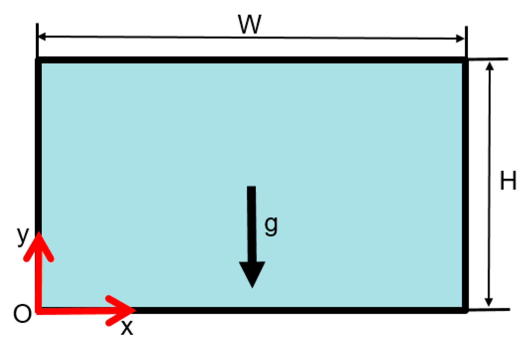
In this section, a parametric study on the aspect ratio of enclosure heated by different walls for a given cross-sectional area, i.e., the same thermal storage capacity, is presented to compare their melting rates. Considering the dimensionless melting time is related to the height of the enclosure, then for the cases with different aspect ratios, the unit of dimensionless melting time corresponds to different real-time. In order to make the comparison clear enough, the results are presented in a real physical unit in this section. Firstly, the three typical enclosures of different aspect ratios of 0.5, 1.0, and 2.0 are selected to illustrate the influence of aspect ratio and a different heated side.
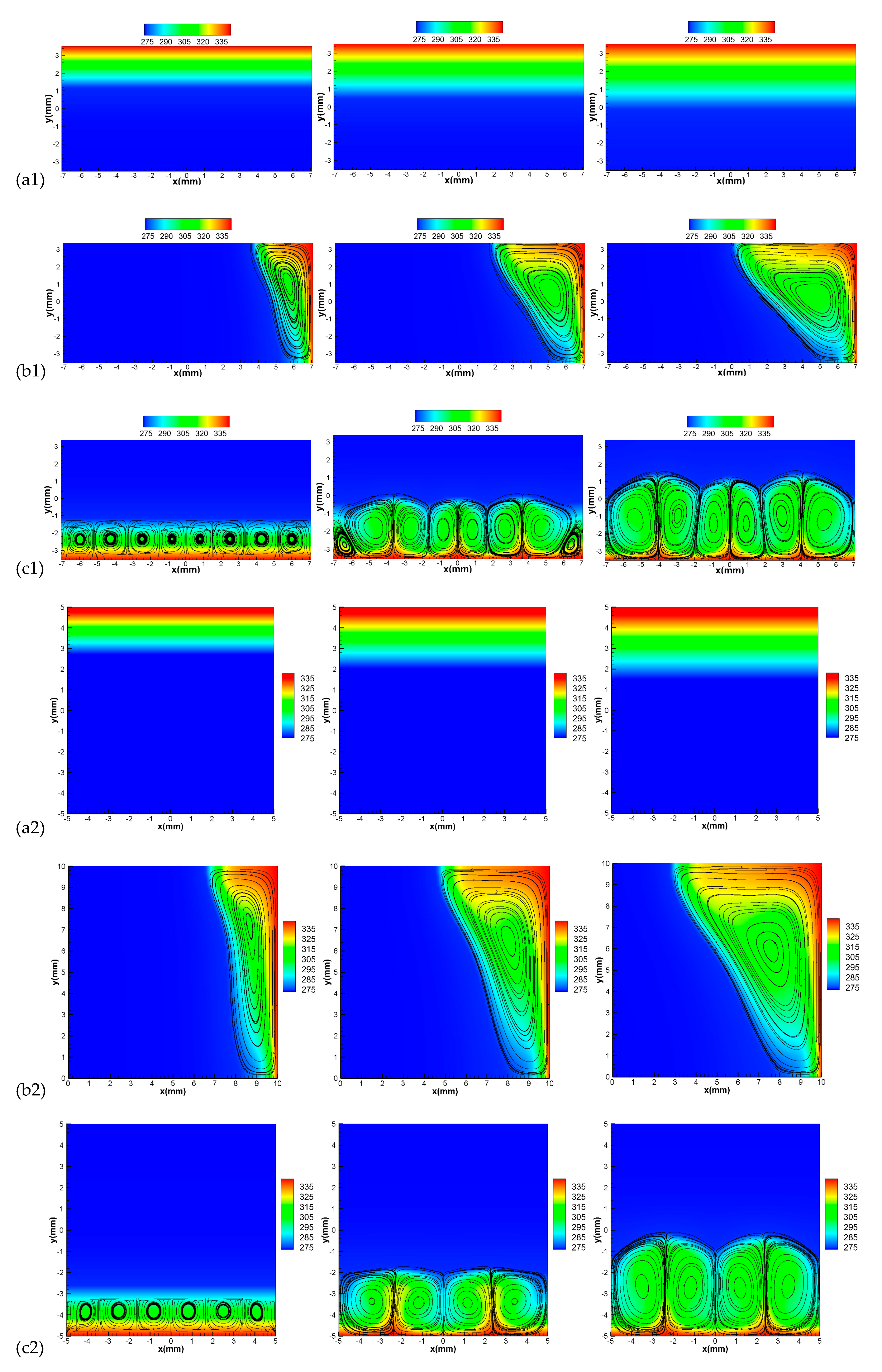
Figure 7 shows the temperature contours and streamlines of the PCM melting in the three different horizontal enclosures heated from the top, right, and bottom sides to illustrate the influence of aspect ratio and different heated sides. It is noted that the heat transfer for the top heated case is obviously only dependent on conduction. The heat flux is doubtless the minimum among the three different heated walls and could even be calculated without simulation. However, this study still made the simulation in order to extract the critical time on the transition from conductive to the convective regime for the bottom heated case as it includes the both effective after a critical transitional time. It is clear that even though the mass of the PCM in these three different enclosures is the same, the melting front, as well as the melting of PCM at given instants, exhibit non-trivial differences.
At the time of 30 s, the interfaces of PCM in these enclosures heated from the top or bottom side is approximately planar and has equivalent distance to the heated wall, which suggests that the heat transfer is dominative in conductive regime, although there are even number of rolls at the bottom of enclosures when heated from below, as shown in Figure 7. The rolls are approximately square which suggests that the influence of buoyancy is working but weak so that the width of the roll is as large as the height of rolls. However, when the right side is heated, the buoyancy of PCM plays a more important role since the effective height is much larger than the other two cases. Consequently, the influence of natural convection is dominative, and the fluid with the higher temperature near the top of the enclosure facilitates the melting of PCM and vice versa. Ultimately, an approximately triangle liquid cavity is produced. As the melting goes on, the height of the fluid zone increases for the bottom heated cases. Consequently, the corresponding effective Rayleigh number increases, which is defined based on the real averaged height of liquid instead of the height of the enclosure (H). Then the bottom heated case switch to convective regimes. Meanwhile, the rolls deform to irregular shapes to facilitate heat transfer, as shown in Figure 7.
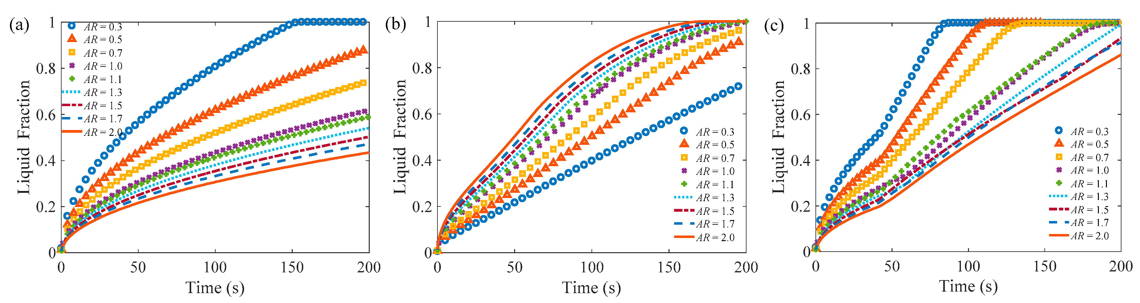
Figure 8 displays the evolutional liquid fraction in the three different enclosures by heating the different sides. In Figure 8a,b, the melting of PCM in the enclosure heated from below is faster than the other two situations. However, this rule can be not applied to the enclosure with AR = 2.0, where the melting rate of PCM in the enclosure heated from the right side is the fastest (see Figure 8c). It indicates that increasing the aspect ratio can be converted from bottom heating dominant to right heating dominant. Because not only the size of the right side becomes larger but also the effective Rayleigh number becomes larger, to enhance the heat transfer of the unit area. Then, it can be known that the right heated case has a higher melting rate as AR = 2.0 and the higher melting rate of the bottom heated case occurs in the range of 0.5 ≤ AR ≤ 1.
When the melting process is dominated by the conductive regime, the corresponding Nusselt number has the scaling law as follow [38]:
Nu θ 1 2
For the melting process in the quasi-steady convection regime, there is also a corresponding boundary layer convective scaling law [38]. It well agrees with the 1/4 law of Rayleigh number as below:
Nu Ra 1 4
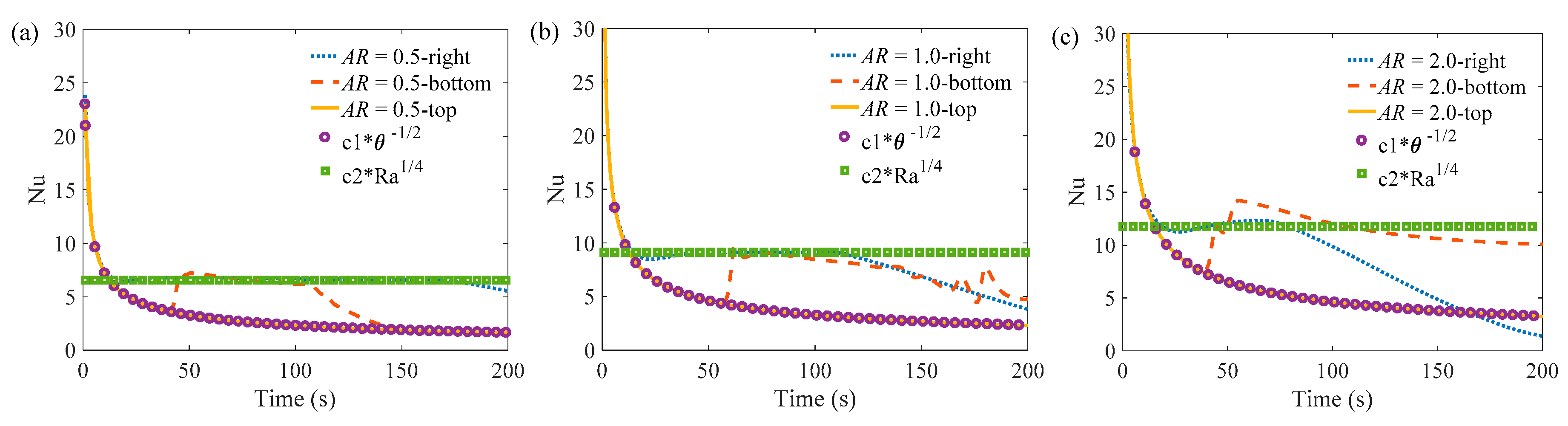
Figure 9 shows the evolution of Nusselt numbers on the heated sides as well as a comparison to theoretical prediction [38]. The best coefficients for the above-mentioned scaling law are fitted and listed in Table 2 for these three enclosures. It is clear that the invariant coefficient 1.155 is satisfied for the conductive regime and the coefficients for the convective regime are a litter bit affected by the increased Rayleigh number range from 0.397 to 0.411. The reason could be explained by the comparable trivial contribution of conduction in these convection regimes. To simplify the analysis, an invariant coefficient of 0.4 as an acceptable value is proposed for these cases.
In Figure 9, it can be observed that the Nusselt numbers are in a good agreement with the scaling law as stated in Equations (12) and (13) when the enclosures are heated from the top and right sides. It is also demonstrated that convection is the main factor during the late stage of the melting of PCM in enclosures heated from the right side. The melting of PCM in rectangular enclosures heated from below is affected by conduction first and then by convection through a clear transition.
Since the aspect ratio plays an important role in the melting of PCM in the rectangular enclosures, its influence on melting is checked in detail. Figure 10 shows the evolutional liquid fraction for the PCM melting process in rectangular enclosures with many different aspect ratios by heating the different sides. The evolutional liquid fraction monotonously varies with the influence of aspect ratio. It is indicated that the higher melting rate is supported by a larger heated surface for all cases. From Figure 10b, it is observed that there is a transition of the curves at a larger aspect ratio for the right heated case. It could be explained by the fact that the top side of the cavity is melted into the liquid so that the area of the melting front reduces. Furthermore, the transition comes early as the increase of aspect ratio.
Nusselt number of the PCM in the cavity is plotted in Figure 11. For the right heated side (Figure 11b), it is observed that the Nusselt number slightly decreases at the end of the melting process, and the drop in the Nusselt number increases as the aspect ratio increases. In fact, the melting front does not advance at the same pace so that there is also a residual solid zone as part of the top is liquid. In Figure 11c, an interesting phenomenon is that there are two obvious peaks of Nusselt number during the melting process, especially for the small aspect ratio cases. One of the peaks could be explained by the transition from conduction to convection. The other peak of Nusselt number could be the reason due to the influence of the decreasing number of rolls in flow fields.
Figure 12 plots the variation of enthalpy along the melting periods. The curves of enthalpy have similar behavior as that of the liquid fraction of PCM. It is noted that the initial value of the enthalpy is negative because the PCM is undercooled initially. Although the trend of these curves is not affected by different aspect ratios, it is obvious that the melting rate is highly dependent on it. How to evaluate the influence of aspect ratio on the melting rate of PCM is essential to the design of some energy storage devices. The foremost works are to describe the problem in a non-dimensional way and identify the possible critical time from the conductive regime to the existing convective regime under the influence of the aspect ratio.

4. Analysis and Correlation

Considering that the melting of PCM is widely used in many significant industrial fields, its physical mechanism attracts many pioneer researchers. However, it is widely admitted that the melting phenomenon is quite complicated so that Viskanta thought that no unified theoretical treatment was achieved [33]. The instantaneous shape of the solid-liquid interface of PCM is the results of the strong coupling between the complicated flows of liquid and the melting rate of solid. Therefore, this work does not aim to study the theoretical solution on a present problem but to present the semi-empirical mathematical expression based on the basic fundamental understanding of this problem as well as the correlation of present numerical simulations. The purpose is to guide the design of the rectangular enclosure with the right aspect ratio and heated wall.
One of the fundamental understandings of the melting of PCM is that it contains at least conductive and convective regimes for the bottom or lateral heated cases. In fact, more heat transfer regimes on the melting of PCM are proposed in the literature but their influence is comparatively slight and ignores here to simplify the analysis. Based on the comparison between top and bottom heated cases, one could extract a critical time on the transition of the heat transfer regime and it is supposed to be related to aspect ratio. For the bottom side heated cases, it is essential to achieve the critical time when natural convection takes over conduction in the melting process. Then the influence of aspect ratio on these critical time are plotted, as shown in Figure 13. It is clear that the dimensionless critical time θc is inversely proportional to the aspect ratio of rectangular enclosures, approximately.
By introducing the critical dimensionless time, it is reasonable to divide the melting process into two parts for the bottom heated cases. Another issue is to unify the influence of aspect ratio as shown by the scattering curves in Figure 10, Figure 11 and Figure 12 in a dimensionless way. In fact, for the top heated case, the unified non-dimensional relation is immediately available when the physical parameter is non-dimensional. For the lateral and bottom heated cases, the non-dimensional melting time should be implemented to separate the influence between conduction and convection. By fitting the results above, the liquid fraction and Nusselt number are plotted, as well as dimensionless specific enthalpy in a consistent way, as shown in Figure 14, Figure 15 and Figure 16.
Figure 14 shows the fitted correlations of the liquid fraction compared with the numerical results. And these correlations are proposed in Equations (14)–(18). When the top side is heated, the liquid fraction with different AR collapse to a single curve as expected when these data are plotted versus dimensionless time θ. The problem is essentially independent on the AR, as shown in Figure 14a. The liquid fraction (LF) in this case can be calculated as follows:
L F = 1.263 θ 0.5167
When the right side is heated, the aspect ratio plays an important role. By using nonlinear regression analysis, the correlation of liquid fraction (LF) could be approximated as follows:
L F = 0.388 X 3 + 0.388 X 2 + 0.921 X
where,
X = A R [ ( ( 1.571 θ ) 0.5167 ) 3.5 + ( 0.22 θ Ra 0.25 ) 3.5 ] 1 3.5
In the above equation, the influence of conduction and convection is distinguished with different exponential relation to non-dimensional melting time. Then the liquid fraction with different AR is approximately convergent to the approximate correlation, as shown in Figure 14b. When the bottom side is heated, the fitted correlation should be divided into two parts by critical dimensionless time θc, which could be calculated as follows:
θ c = c A R 0.9812
where c is a coefficient dependent on the variation of the cross-sectional area ((A/Aref)1.5), in order to consider the geometrical contribution on Rayleigh number, in this study, it is 0.05436. By separating the different regimes, the correlation of liquid fraction (LF) can be approached by following expressions according to the dimensionless melting time:
L F = { 1.263 θ 0.5167 θ θ c 0.165 θ Ra 0.25 A R 0.1 θ > θ c
It is found that the liquid fraction has an exponential relation to AR in the convective regime. The above mathematical expressions on the melting process provide the ability to compare and quantify the melting rate by heating different sides of the rectangular enclosure with different aspect ratios. Especially, in the range of aspect ratio that could provide a higher melting rate by heating the bottom side than that by heating the right side. The answer is given in the last part of this paper by plotting the neutral curve, which provides the critical aspect ratios in the Rayleigh number versus aspect ratio diagram when the bottom and lateral heated wall need the same melting time.
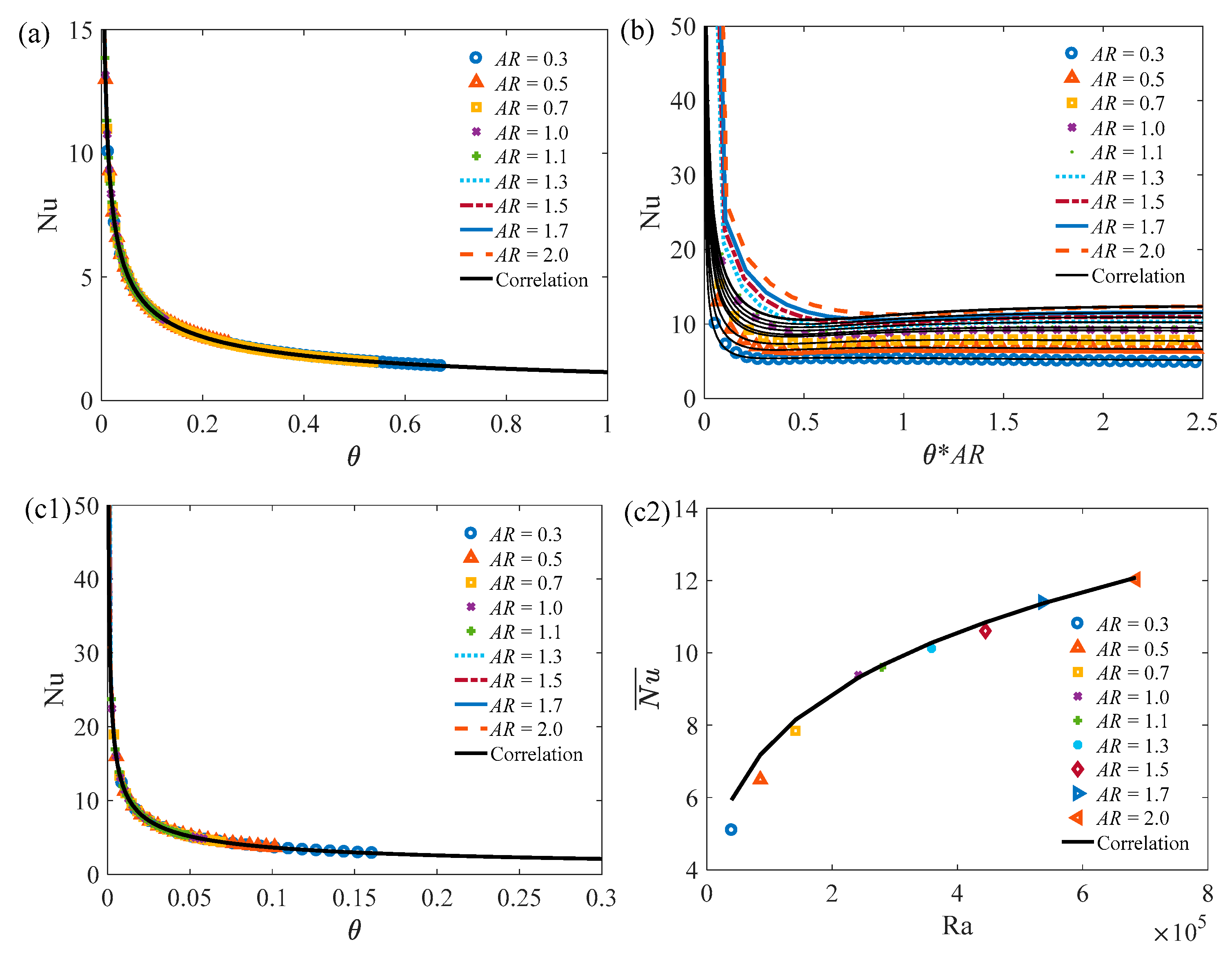
In the same way, the correlation of Nusselt number for the melting process is also proposed based on different heated side. Figure 15 shows the fitted correlations of Nusselt number compared with the numerical results. And these correlations are shown in Equations (19)–(21). In Figure 15a, when the top side is heated, the fitted correlation is as follows:
Nu = 1.155 θ 0.5
When the right side is heated, Jany and Bejan [38] proposed a unified mathematical expression for the Nusselt number based on conduction, convection, and mixing regimes of heat transfer. They also presented the necessary empirical constants based on their numerical simulation. In this work, the influence of the aspect ratio is also considered. When the aspect ratio is implemented in their expression and the empirical constant is slightly adjusted, it can be found that the Nusselt number can be calculated as follows:
Nu = 3.7851 θ 0.502 + 0.3465 A R 0.1 Ra 0.25 1.2617 θ 0.502 1 + ( 0.0175 A R 0.1 Ra 0.35 θ 1.2 ) 2
For the bottom heated cases, it is noticed that the evolutional Nusselt number is irregular by the influence of irregular solid-liquid interface. It is, therefore, unnecessary to fit this irregular curve because it is sensitive to any random process. However, the whole process corresponds to a useful averaged Nusselt number. Hence, here is the above-mentioned correlation as follows:
N u ¯ = { 1.155 θ 0.5 θ θ c 0.4 Ra 0 . 25 θ > θ c
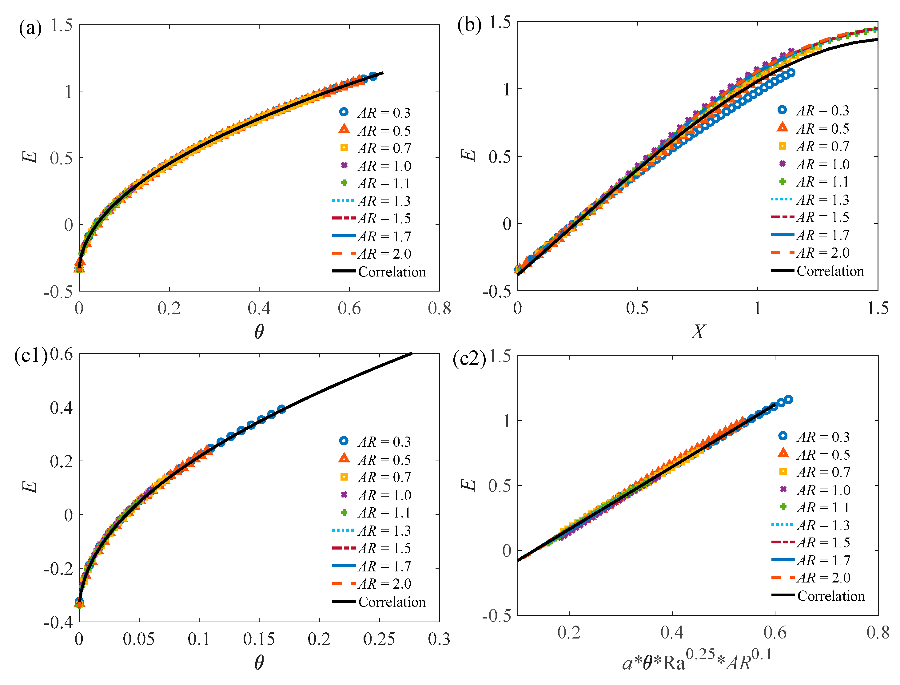
Figure 16 shows the proposed correlations of dimensionless specific enthalpy (normal to latent heat) and its comparison with numerical results. And these proposed correlations, are shown in Equations (22)–(24). In Figure 16a, when the top side is heated, the fitted correlation is as follows:
E = 1.824 θ 0.498 + Q i h s f
In Figure 16b, when the right side is heated, the fitted correlation is as follows:
E = 0.2877 X 3 + 0.1706 X 2 + 1.558 X + Q i h s f
In Figure 16(c1,c2), when the bottom side is heated, the fitted correlation is as follows:
E = { 1.824 θ 0.498 + Q i h s f θ θ c 0.325 θ Ra 0.25 A R 0.1 + Q i h s f θ > θ c
It is obvious that the aspect ratio plays an important role in the convective regime. With above-mentioned correlations, these results could collapse to almost one line.
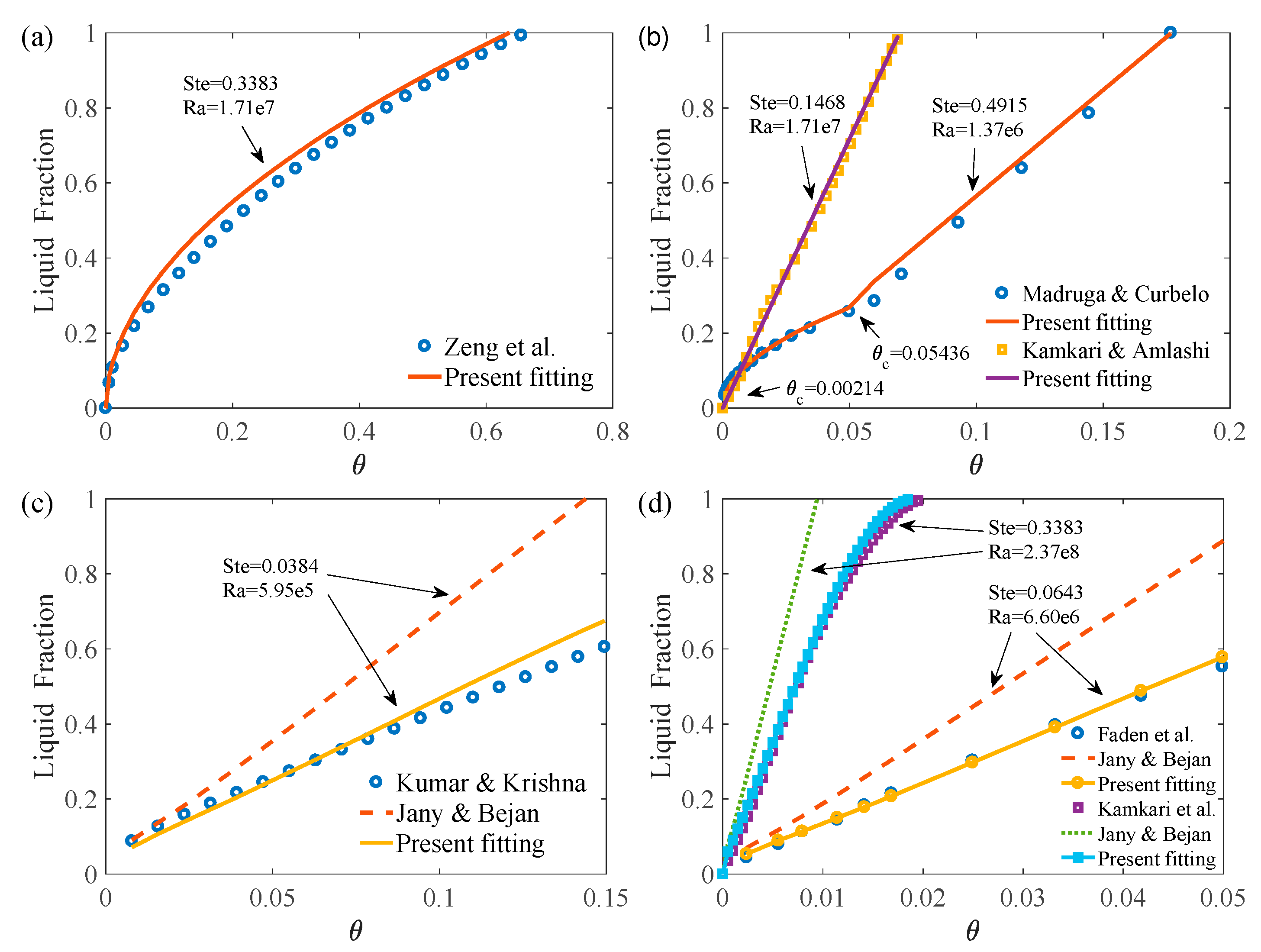
In order to validate the above-mentioned correlations, further evaluation is necessary. Here several independent experimental data are selected by heating a different side [20,28,36,39,40,41] and the available correlation in reference [38] as a comparison is shown in Figure 17. It seems that our proposed correlations are in good agreement with several different independent experimental results. Compare to the previous prediction, the present correlation exhibits a fidelity accuracy. Furthermore, the Rayleigh number in these experiments are in a wide range from 105 to 108 as shown in Table 3, it suggests that our proposed correlation could extend as high Rayleigh number as 108. Hence, these correlations could be used to predict the melting of PCM in different rectangular enclosures by heating the different sides.
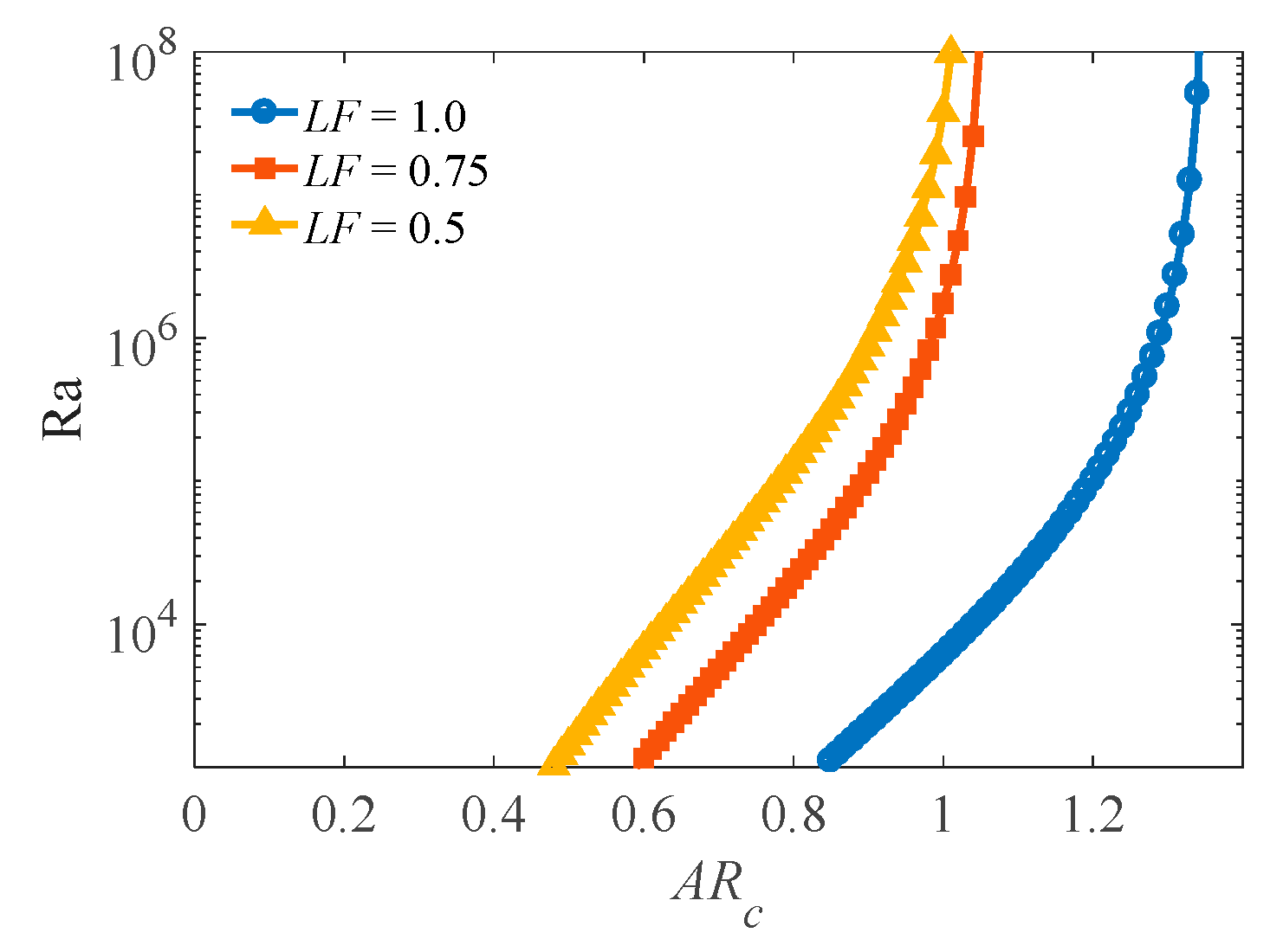
At last, it comes to the theme of this work about how to design a rectangular enclosure of PCM with the same heat storage capacity (the same cross-sectional area) by heating one sole side to achieve higher melting rate. It is clear that the top heated scheme is never possible to be the optimum option. The melting rate of PCM could be enhanced by a small aspect ratio for the bottom heated case or a large one for the lateral wall heated situation. However, the melting rate of PCM could be at the same level by choosing a suitable aspect ratio. By setting the same liquid fraction and non-dimensional melting time in Equations (18) and (21), the neutral curves of critical aspect ratio and its relationship to Rayleigh number can be plotted, as shown in Figure 18.
From the Rayleigh number adopted in the present simulation, the critical aspect ratio is 1.25 when all of the PCM is changed to liquid, i.e., LF = 1.0. In fact, PCMs are not always expected to be melted out in their designing condition of many applications. Therefore, the neutral curves of the critical aspect ratio for LF = 0.5 and LF = 0.75 are also plotted in the same way. For the present numerical work, the corresponding critical aspect ratios are 0.82 and 0.93. It is noted that as the aiming liquid fraction reduces, the critical aspect ratio decreases. Based on the previous numerical results, it is clear that the melting rate is low at the beginning and increases in the evolutional process for the bottom heated cases. On the contrary, the melting rate reduces at the last stage of phase-changing for the lateral heated case. Consequently, the critical aspect ratio reduces as the aiming liquid fraction decreases.
It should be pointed out that the mushy zone constant in the numerical simulations is set to 105, which is the most selected constant, may not be suitable for all kinds of PCM. The reference density is set to the density of liquid PCM. Consequently, the empirical constants of correlation are supposed to be slightly changed based on the variation of mushy zone constant, different PCM, or variable density. The influences of the mushy zone constant and the variable density on the critical aspect ratio are not the scope of this study but would be the future work.

5. Conclusions

Considering the rectangular enclosure is frequently adopted in phase change energy storage, the melting process in the rectangular enclosures with different aspect ratios heated from the different sides are numerically studied in this work. The Rayleigh numbers in these cases are in the order of 105. This study compared the melting rate for the enclosure with the same sectional area but a different aspect ratio with different heated sides. It is clear that the top heated enclosure only affected by the conductive regime, while the other heated sides could also benefit from the convective regime. For the bottom heated side case, the difference to the top heated side is compared to the extract time transition from conductive to the convective regime at a critical time. This transitional time is observed as inversely proportional to the aspect ratio of the rectangular enclosure.
As the aspect ratio increases, the lateral heated side provides a more obvious advantage. On the contrary, the bottom heated side may result in the best melting rate for the small aspect ratio cases. However, the choice of aspect ratio is sometimes limited by many complex factors, such as the cost, the area of the heated surface, available space, and so on. It is obscured to know which one is better between the bottom and laterally heated schemes by their competitive melting rate of PCM as the rectangular enclosure close to be a square. Therefore, it is desirable to know a critical aspect ratio for one scheme better than the other for the design of the phase change energy storage.
In order to recommend the best aspect ratio of rectangular enclosure quantitatively for energy storage, a series of correlations in dimensionless style for the liquid fraction and Nusselt number, as well as the specific enthalpy, are proposed. These correlations are fitted from numerous numerical results and validated for several independent experimental results in a broad range of Rayleigh numbers. It is found that the proposed correlation could also predict the melting process much better than the other available correlation in reference to the rectangular enclosure with different heated sides. The present correlation could also be used for a higher Rayleigh number as large as 108. Base on the comparison of different schemes on the heated side by using the proposed correlation expression, the neutral curves of critical aspect ratio versus Rayleigh number is obtained in a diagram. The diagram shows that when AR < 1.25, the total melting time of PCM in the cavity heated from below is the smallest (LF = 1.0). The critical aspect ratios for LF = 0.5 and LF = 0.75 are respectively, 0.82 and 0.93. This study is helpful for the selection of the appropriate aspect ratio and heating method to achieve excellent comprehensive energy storage performance of PCM.

Author Contributions

J.D. and Y.X. planned the study. J.D. performed all of the numerical simulations. All of the authors validated numerical results. J.D. proposed the paper organization, prepared the original paper. All of the authors revised and edited the final paper.

Funding

This work was funded by the National Natural Science Foundation of China grant number 11872187, 51779097, and the National Nature Science Foundation of Hubei province grant number 2018CFB461. The APC was funded by the National Natural Science Foundation of China.

Acknowledgments

Thanks to SCTS/CGCL HPCC of HUST for providing computing resources and technical support.

Conflicts of Interest

The authors declare no conflict of interest.

Nomenclature

H, Wheight and width of the enclosure [m]
Asection-cross area of enclosure [m2]
Cmush zone constant [kg/m3·s]
Qtotal heat transfer rate [J/kg]
cpspecific heat [J/kg·K]
ppressure [N/m2]
ttime [s]
hsflatent heat [J/kg]
Ttemperature [K]
kthermal conductivity [W/m·K]
especific enthalpy of PCM [J/kg]
u, vvelocity in x and y-direction respectively [m/s]
ggravitational acceleration [m/s2]
acoefficient
ccorrection factor
Edimensionless specific enthalpy
RaRayleigh number
PrPrandtl number
NuNusselt number
SteStefan number
FoFourier number
ARaspect ratio of the rectangular enclosure
Greek symbols
ρdensity [kg/m3]
μdynamic viscosity [kg/m·s]
αthermal diffusivity [m2/s]
βthermal expansion coefficient [K−1]
γliquid fraction
εa small number, typically around 10−3
θthe dimensionless time
Subscripts
refreference point
ssolid
lliquid
mmelting
whot side
iinitial state
ccritical point

References

  1. Ma, T.; Yang, H.; Zhang, Y.; Lu, L.; Wang, X. Using phase change materials in photovoltaic systems for thermal regulation and electrical efficiency improvement: A review and outlook. Renew. Sustain. Energy Rev. 2015, 43, 1273–1284. [Google Scholar] [CrossRef]
  2. Zhou, F.; Ji, J.; Yuan, W.; Zhao, X.; Huang, S. Study on the PCM flat-plate solar collector system with antifreeze characteristics. Int. J. Heat Mass Transf. 2019, 129, 357–366. [Google Scholar] [CrossRef]
  3. Karthick, A.; Murugavel, K.K.; Ramanan, P. Performance enhancement of a building-integrated photovoltaic module using phase change material. Energy 2018, 142, 803–812. [Google Scholar] [CrossRef]
  4. Fang, G.; Tang, F.; Cao, L. Preparation, thermal properties and applications of shapestabilized thermal energy storage materials. Renew. Sustain. Energy Rev. 2014, 40, 237–259. [Google Scholar] [CrossRef]
  5. Al-Zareer, M.; Dincer, I.; Rosen, M.A. Heat transfer modeling of a novel battery thermal management system. Numer. Heat Transf. Part A 2018, 73, 277–290. [Google Scholar] [CrossRef]
  6. Wan, X.F.; Wang, F.; Udayraj. Numerical analysis of cooling effect of hybrid cooling clothing incorporated with phase change material (PCM) packs and air ventilation fans. Int. J. Heat Mass Transf. 2018, 126, 636–648. [Google Scholar] [CrossRef]
  7. Stropnik, R.; Stritih, U. Increasing the efficiency of PV panel with the use of PCM. Renew. Energy 2016, 97, 671–679. [Google Scholar] [CrossRef]
  8. Emam, M.; Ahmed, M. Cooling concentrator photovoltaic systems using various configurations of phase-change material heat sink. Energy Convers. Manag. 2018, 158, 298–314. [Google Scholar] [CrossRef]
  9. Liu, M.; Tay, N.H.S.; Bell, S.; Belusko, M.; Jacob, R.; Will, G.; Saman, W.; Bruno, F. Review on concentrating solar power plants and new developments in high temperature thermal energy storage technologies. Renew. Sustain. Energy Rev. 2016, 53, 1411–1432. [Google Scholar] [CrossRef]
  10. Elarga, H.; Fantucci, S.; Serra, V.; Zecchin, R.; Benini, E. Experimental and numerical analyses on thermal performance of different typologies of PCMs integrated in the roof space. Energy Build. 2017, 150, 546–557. [Google Scholar] [CrossRef] [Green Version]
  11. Komerska, A.; Bianco, L.; Serra, V.; Fantucci, S.; Rosinski, M. Experimental analysis of external dynamic solar shading integrating PCMs: First results. Energy Procedia 2015, 78, 3452–3457. [Google Scholar] [CrossRef]
  12. Hong, Y.X.; Ye, W.B.; Huang, S.M.; Du, J. Can the melting behaviors of solid-liquid phase change be improved by inverting the partially thermal-active rectangular cavity. Int. J. Heat Mass Transf. 2018, 126, 571–578. [Google Scholar] [CrossRef]
  13. Wu, Z.G.; Sheng, W.C.; Tao, W.Q.; Li, Z. A novel experimental-numerical method for studying the thermal behaviors of phase change material in a porous cavity. Sol. Energy 2018, 169, 325–334. [Google Scholar] [CrossRef]
  14. Biwole, P.H.; Groulx, D.; Souayfane, F.; Chiu, T. Influence of fin size and distribution on solid-liquid phase change in a rectangular enclosure. Int. J. Therm. Sci. 2018, 124, 433–446. [Google Scholar] [CrossRef]
  15. Yilbas, B.S.; Shuja, S.Z.; Shaukat, M.M. Thermal Characteristics of Latent Heat Thermal Storage: Comparison of Aluminum Foam and Mesh Configurations. Numer. Heat Transf. Part A 2015, 68, 99–116. [Google Scholar] [CrossRef]
  16. Al-Maghalseh, M.M. Investigate the Natural Convection Heat Transfer in A PCM Thermal Storage System Using ANSYS/FLUENT. Jordan J. Mech. Ind. Eng. 2017, 11, 217–223. [Google Scholar]
  17. Elbahjaoui, R.; Qarnia, H.E. Thermal analysis of nanoparticle-enhanced phase change material solidification in a rectangular latent heat storage unit including natural convection. Energy Build. 2017, 153, 1–17. [Google Scholar] [CrossRef]
  18. Zhang, J.J.; Qu, Z.G.; Liu, Y. Numerical study on the melting thermal characteristics of a microencapsulated phase change plate. Numer. Heat Transf. Part A 2016, 70, 99–419. [Google Scholar] [CrossRef]
  19. Duan, J.; Xiong, Y.L.; Yang, D. Melting Behavior of Phase Change Material in Honeycomb Structures with Different Geometrical Cores. Energies 2019, 12, 2920. [Google Scholar] [CrossRef]
  20. Kamkari, B.; Amlashi, H.J. Numerical simulation and experimental verification of constrained melting of phase change material in inclined rectangular enclosures. Int. Commun. Heat Mass Transf. 2017, 88, 211–219. [Google Scholar] [CrossRef]
  21. Zhao, J.D.; Zhai, J.; Lu, Y.H.; Liu, N. Theory and experiment of contact melting of phase change materials in a rectangular cavity at different tilt angles. Int. J. Heat Mass Transf. 2018, 120, 241–249. [Google Scholar] [CrossRef]
  22. Saeed, K.M.; Aikkara, R.; Kadengal, A. Analysis and Optimisation of Melting Rate of Solids PCM for Various Shapes and Configurations. Int. J. Emerg. Eng. Res. Technol. 2014, 2, 173–183. [Google Scholar]
  23. Jourabian, M.; Farhadi, M.; Darzi, A.A.R. Heat transfer enhancement of PCM melting in 2D horizontal elliptical tube using metallic porous matrix. Theor. Comput. Fluid Dyn. 2016, 30, 579–603. [Google Scholar] [CrossRef]
  24. Hong, Y.X.; Ye, W.B.; Huang, S.M.; Yang, M.L.; Du, J. Thermal storage characteristics for rectangular cavity with partially active walls. Int. J. Heat Mass Transf. 2018, 126, 683–702. [Google Scholar] [CrossRef]
  25. Fantucci, S.; Goia, F.; Perino, M.; Serra, V. Sinusoidal response measurement procedure for the thermal performance assessment of PCM by means of dynamic heat flow meter apparatus. Energy Build. 2019, 183, 297–310. [Google Scholar] [CrossRef]
  26. Shokouhmand, H.; Kamkari, B. Experimental investigation on melting heat transfer characteristics of lauric acid in a rectangular thermal storage unit. Exp. Therm. Fluid Sci. 2013, 50, 201–212. [Google Scholar] [CrossRef]
  27. Gong, Z.X.; Devahastin, S.; Mujumdar, A.S. Enhanced heat transfer in free convection-dominated melting in a rectangular cavity with an isothermal vertical wall. Appl. Therm. Eng. 1999, 19, 1237–1251. [Google Scholar] [CrossRef]
  28. Madruga, S.; Curbelo, J. Dynamic of plumes and scaling during the melting of a Phase Change Material heated from below. Int. J. Heat Mass Transf. 2018, 126, 206–220. [Google Scholar] [CrossRef] [Green Version]
  29. Kousksou, T.; Mahdaoui, M.; Ahmed, A.; Msaad, A.A. Melting over a wavy surface in a rectangular cavity heated from below. Energy 2014, 64, 212–219. [Google Scholar] [CrossRef]
  30. Konig-Haagen, A.; Franquet, E.; Pernot, E.; Brüggemann, D. A comprehensive benchmark of fixed-grid methods for the modeling of melting. Int. J. Therm. Sci. 2017, 118, 69–103. [Google Scholar] [CrossRef]
  31. Brent, A.D.; Voller, V.R.; Reid, K.J. Enthalpy-porosity technique for modeling convection-diffusion phase change: Application to the melting of a pure metal. Numer. Heat Transf. Part A Appl. 1988, 13, 297–318. [Google Scholar]
  32. Hong, Y.X.; Ye, W.B.; Du, J.; Huang, S.M. Solid-liquid phase-change thermal storage and release behaviors in a rectangular cavity under the impacts of mushy region and low gravity. Int. J. Heat Mass Transf. 2019, 130, 1120–1132. [Google Scholar] [CrossRef]
  33. Kakac, S.; Aung, W.; Viskanta, R. Natural Convection: Fundamentals and Applications; Hemisphere: Washington, DC, USA, 1985. [Google Scholar]
  34. Xiong, Y.L.; Bruneau, C.H.; Yang, D. Numerical study on viscoelastic fluid flow past a rigid body. Appl. Math. Model. 2017, 42, 188–208. [Google Scholar] [CrossRef]
  35. Hannoun, N.; Alexiades, V.; Mai, T.Z. A reference solution for phase change with convection. Int. J. Numer. Methods Fluids 2005, 48, 1283–1308. [Google Scholar] [CrossRef]
  36. Faden, M.; Linhardt, C.; Höhlein, S.; König-Haagen, A.; Brüggemann, D. Velocity field and phase boundary measurements during melting of n-octadecane in a cubical test cell. Int. J. Heat Mass Transf. 2019, 135, 104–114. [Google Scholar] [CrossRef]
  37. Kahraman, R. Numerical and experimental investigation of melting of ice involving natural convection. Int. J. Energy Res. 2002, 26, 347–354. [Google Scholar] [CrossRef]
  38. Jany, P.; Bejan, A. Scaling theory of melting with natural convection in an enclosure. Int. J. Heat Mass Transf. 1988, 31, 1221–1235. [Google Scholar] [CrossRef]
  39. Zeng, L.Y.; Lu, J.; Li, Y.C.; Li, W.Y.; Liu, S.L.; Zhu, J. Numerical study of the influences of geometry orientation on phase change material’s melting process. Adv. Mech. Eng. 2017, 9. [Google Scholar] [CrossRef]
  40. Kamkari, B.; Shokouhmand, H.; Bruno, F. Experimental investigation of the effect of inclination angle on convection-driven melting of phase change material in a rectangular enclosure. Int. J. Heat Mass Transf. 2014, 72, 186–200. [Google Scholar] [CrossRef]
  41. Kumar, M.; Krishna, D.J. Influence of Mushy Zone Constant on Thermohydraulics of a PCM. Energy Procedia 2017, 109, 314–321. [Google Scholar] [CrossRef]
Figure 1. The schematic of rectangular section.
Energies 12 03100 g001
Figure 2. The verification of grid independence at the time step 0.1 s for AR = 1. (a) Heating the top side; (b) heating the right side; (c) heating the bottom side.
Energies 12 03100 g002
Figure 3. Independence analysis of time step size for AR = 1 with the grid number 12,321. (a) Heating the top side; (b) heating the right side; (c) heating the bottom side.
Energies 12 03100 g003
Figure 4. Numerical validation with reference [35]. (a) Melting front; (b) liquid fraction.
Energies 12 03100 g004
Figure 5. Validation of the present numerical model with the experimental data reported by Faden et al. [36]. (a) Melting front; (b) liquid fraction.
Energies 12 03100 g005
Figure 6. Validation of the present numerical model with the experimental data reported by Kahraman [37]. (a) Liquid fraction; (b) temperature profile of centerline (x = 0.1 m, 0 ≤ y ≤ 0.2 m) at time = 1.7 h.
Energies 12 03100 g006
Figure 7. Temperature contours with streamlines at t = 30 s, 50 s, 70 s. (a1)–(a3) Heating the top side; (b1)–(b3) heating the right side; (c1)–(c3) heating the bottom side.
Energies 12 03100 g007aEnergies 12 03100 g007b
Figure 8. The evolutional liquid fraction in three enclosures by heating the different sides. The evolutional liquid fraction in three enclosures by heating the different sides. (a) AR = 0.5; (b) AR = 1.0; (c) AR = 2.0.
Energies 12 03100 g008
Figure 9. The Nusselt number of three different enclosures with different hot sides. (a) AR = 0.5; (b) AR = 1.0; (c) AR = 2.0.
Energies 12 03100 g009
Figure 10. Evolution of the liquid fraction of the phase change material (PCM) in rectangular enclosures with different aspect ratios by heating the different sides. (a) Heating the top side; (b) heating the right side; (c) heating the bottom side.
Energies 12 03100 g010
Figure 11. Nusselt numbers of the PCM in rectangular enclosures with different aspect ratios by heating the different sides. (a) Heating the top side; (b) heating the right side; (c) heating the bottom side.
Energies 12 03100 g011
Figure 12. Enthalpy of the PCM in rectangular enclosures with different aspect ratios by heating the different sides. (a) Heating the top side; (b) heating the right side; (c) heating the bottom side.
Energies 12 03100 g012
Figure 13. Dimensionless time θc corresponding to the critical point when the bottom side is heated.
Energies 12 03100 g013
Figure 14. Unified results for the liquid fraction of PCM in rectangular enclosures with different aspect ratios. (a) Heating the top side; (b) heating the right side; (c1) heating the bottom side (θθc); (c2) heating the bottom side (θ > θc).
Energies 12 03100 g014
Figure 15. Unified results for the Nusselt number of PCM in rectangular enclosures with different aspect ratios. (a) Heating the top side; (b) heating the right side; (c1) heating the bottom side (θθc); (c2) heating the bottom side (θ > θc).
Energies 12 03100 g015
Figure 16. Unified results for dimensionless enthalpy of PCM in rectangular enclosures with different aspect ratios. (a) Heating the top side; (b) heating the right side; (c1) heating the bottom side (θθc); (c2) heating the bottom side (θ > θc).
Energies 12 03100 g016
Figure 17. Validation of the results of the references by using the proposed fitted correlations. (a) Heating the top side [39]; (b) heating the bottom side [20,28]; (c) heating the lateral side [41]; (d) heating the lateral side [36,40].
Energies 12 03100 g017
Figure 18. The neutral curves of the critical aspect ratio when the bottom heated wall and lateral heated wall need the same melting time.
Energies 12 03100 g018
Table 1. Thermophysical properties of pure tin [35], n-octadecane [36], and ice [37].
ParameterSymbolTin (505–508 K)N-Octadecane (298–301 K)Ice/Water (270–343.15 K)
Density [kg/m3]ρsl7500/7500867/775.60903/998
Specific heat capacity [J/kg·K]cps/cpl200/2001900/22402091/4182
Thermal conductivity [W/m·K]ks/kl60/600.32/0.152.367/0.624
Dynamic viscosity [kg/m·s]μ6 × 10−33.75 × 10−31.003 × 10⁻³
Thermal expansion coefficient [1/K]β2.67 × 10−48.36 × 10−45.1 × 10⁻⁵
Latent heat [J/kg]hsf60,000243,680333,790
Melting temperature [K]Tm505.04301.15273.15
Prandtl numberPr0.0256.06.722
Table 2. The corresponding parameters and coefficients in Figure 10.
EnclosuresHeight [mm]RaPrc1c2
AR = 0.57.07185,6116.7221.1550.397
AR = 1.010.0242,1526.7221.1550.411
AR = 2.014.142684,9086.7221.1550.409
Table 3. The parameters from the references.
CaseZeng et al. [39] (Lauric Acid)Madruga et al. [28] (N-Octadecane)Kamkari et al. [20] (Lauric Acid)Kumar et al. [41] (Gallium)Kamkari et al. [40] (Lauric Acid)Faden et al. [36] (N-Octadecane)
Ste0.33830.49150.14680.03840.33830.0643
Ra1.7119 × 1071.3747 × 1061.7119 × 1075.9480 × 1052.3666 × 1086.6011 × 106
Pr88.571960.812388.57190.021688.571956.0
α7.5645 × 10−87.6287 × 10−87.5645 × 10−81.3767 × 10−57.5645 × 10−81.1512 × 10−7
H/W0.05/0.120.01/0.010.05/0.120.0635/0.08890.12/0.050.04/0.04

