Article

An Optimal Energy Management System for Real-Time Operation of Multiagent-Based Microgrids Using a T-Cell Algorithm

by
Fatima Zahra Harmouch
1,2,
Ahmed F. Ebrahim
2,
Mohammad Mahmoudian Esfahani
2,
Nissrine Krami
1,
Nabil Hmina
1 and
Osama A. Mohammed
2,*
1
Laboratory Systems Engineering (LGS) ENSA, Ibn Tofail University, Kenitra, B.P 241, Morocco
2
Energy Systems Research Laboratory, Department of Electrical and Computer Engineering, Florida International University, Miami, FL 33174, USA
*
Author to whom correspondence should be addressed.
Energies 2019, 12(15), 3004; https://doi.org/10.3390/en12153004
Submission received: 25 June 2019 / Revised: 26 July 2019 / Accepted: 30 July 2019 / Published: 3 August 2019
(This article belongs to the Special Issue Multi-Agent Energy Systems Simulation)

Abstract

:
The real-time operation of the energy management system (RT-EMS) is one of the vital functions of Microgrids (MG). In this context, the reliability and smooth operation should be maintained in real time regardless of load and generation variations and without losing the optimum operation cost. This paper presents a design and implementation of a RT-EMS based on Multiagent system (MAS) and the fast converging T-Cell algorithm to minimize the MG operational cost and maximize the real-time response in grid-connected MG. The RT-EMS has the main function to ensure the energy dispatch between the distributed generation (DG) units that consist in this work on a wind generator, solar energy, energy storage units, controllable loads and the main grid. A modular multi-agent platform is proposed to implement the RT-EMS. The MAS has features such as peer-to-peer communication capability, a fault-tolerance structure, and high flexibility, which make it convenient for MG context. Each component of the MG has its own managing agent. While, the MG optimizer (MGO) is the agent responsible for running the optimization and ensuring the seamless operation of the MG in real time, the MG supervisor (MGS) is the agent that intercepts sudden high load variations and computes the new optimum operating point. In addition, the proposed RT-EMS develops an integration of the MAS platform with the Data Distribution Service (DDS) as a middleware to communicate with the physical units. In this work, the proposed algorithm minimizes the cost function of the MG as well as maximizes the use of renewable energy generation; Then, it assigns the power reference to each DG of the MG. The total time delay of the optimization and the communication between the EMS components were reduced. To verify the performance of our proposed system, an experimental validation in a MG testbed were conducted. Results show the reliability and the effectiveness of the proposed multiagent based RT-EMS. Various scenarios were tested such as normal operation as well as sudden load variation. The optimum values were obtained faster in terms of computation time as compared to existing techniques. The latency from the proposed system was 43% faster than other heuristic or deterministic methods in the literature. This significant improvement makes this proposed system more competitive for RT applications.

1. Introduction

Technology has shaped our modern life in many aspects: starting by smart TV, passing by smart phones and ending by Smart Grid. The power system which is conventionally structured as generation, transmission and distribution is reshaped as an agglomeration of Microgrids (MGs). The idea behind such a new structure is the increasing distributed energy resource (DER) mainly renewable energy that has been installed in the low voltage (LV) networks. Injecting power into the distribution power system is a new phenomenon which must be dealt with. This is where the smart cyber systems interfere. Information technologies has been integrated with the power system enabling, as consequence, the smart control of DG and make it possible for the MG to operable autonomously without being connected to the grid. Besides, such structure favorizes the interaction of the costumer to become an active player in the system and control its load depending on the distribution network operator.
The information system responsible for the control and economical optimization of MG is known as the energy management system (EMS). The EMS comprises three parts. The primary, secondary and tertiary control. More details on the primary, secondary could be found in [1,2]. This work focuses on the tertiary control. One of the most crucial tasks of a real-time EMS in grid-connected MG is to satisfy the minimum total operation cost while meeting the energy balance between different DER, storage units, controllable loads and the power exchanged with the main grid under their specific constraints. This is called in the literature review as the economic dispatch problem or the economic load dispatch problem. To solve this issue, several optimization methods have been used in the past decades. All of them can be categorized into two main categories: Classical and evolutionary algorithms.
In the conventional power system, the problem is modeled as a quadratic cost function which is solved by classical methods such as Lagrange multiplier method, base point participation factor, lambda iteration, Newton’s method, gradient method, mixed integer linear programming, and linear programming [3]. Most of previous works presented a power dispatch of thermal generators which makes the cost function considered not suitable for MG optimization [4,5]. Besides, some of those used technics suffer from some limitations such as the assumption that the incremental cost curves of the generation units are monotonically increasing piecewise linear functions and the high dependency on the specific mathematical model. Even if dynamic programming could be used to solve the economic dispatch, it presents a complex solutions that is not appropriate for real time application [6]. Furthermore, it is not possible to apply such methods in real time specially with a MG containing a large number of components.
In this respect, evolutionary algorithms were introduced to overcome those limitations. The heuristic evolutionary algorithms are inspired from the natural and social behavior of animals and organisms [3]. For instance, genetic algorithm, improved genetic algorithm were based on genes behavior, while evolutionary programming, ant colony metaheuristic, artificial bee colony, particle swarm optimization and artificial neural network are based on swarm behavior of insects and micro-organisms. However, even if some of these methods present competitive results, still some of them suffer from the curse of local optimality in some cases [7]. The literature review reveals that most of previous work were considering a day ahead optimization and not taking the real time constraint into consideration [8]. More recent works present the real time operation of energy management in MG [9,10]. However, some of the work were based on simulations and did not experiment the RT operation in real testbed, while other work did not consider the point of single failure of the system. A RT framework for EMS of MG using MAS were considered in [11], however there was no cost optimization in the system.
Since deterministic optimization methods are time consuming to reach the optimal solution for problems with large dimensions, evolutionary algorithms were introduced to overcome this limitation. The main advantage of these solutions is that they solve complex problems with non-deterministic polynomial problem. Furthermore, in the MG context, while the EMS is running in real time, solving the ED optimization time is also a crucial parameter. Thus, looking for a fast optimization technique is essential.
In this work, the T-Cell algorithm is presented as a heuristic method inspired by immunobiology to solve ED in RT. The algorithm was first introduced in [12]. The T-Cell algorithm is inspired by the mediated immune cells in the human body. The T-Cell or as known in the immunobiology, helper T-Cells play a key role in the adaptative immune response. During their life, helper T-cells experience three phases. During the first phase of their life, they develop in the Thymus, then they immigrate and start circulating between the bloodstream and lymphoid tissue. At this stage, they are known as a naïve helper T-cells. Then in the second phase, the naïve T-cells encounter an antigen-presenting cell. This latter binds to the peptide and protein receptors at the cell surface which results in the T-Cell activation. Once activated, the cell starts proliferating and differentiating. This is the third phase. Helper T-Cell differentiate into either T helper 1 or T helper 2 effector cells, depending on their environment’s composition. Each type of effector cell helps to eliminate the antigen presented in the activation process [13]. Therefore, during an antibody intrusion, the T-Cells proliferate by generating other clones of themselves; then, each clone differentiates by acquiring new proprieties to destroy the intrusion [14]. The authors in [15] tested the performance of T-Cell algorithm compared to other optimization heuristics. The algorithm presents a competitive result in term of convergence and execution time.
However, the optimization is just one part of an EMS. The EMS in the context of MGs deals with all management aspects of MG. It must coordinate between different DERs, supervise the network in case of load or generation fluctuation and make sure that energy balance is satisfied all time. A multi-agent system (MAS) is well suited in this context. MAS knew lot of improvement during last years. The nature of the modular and decentralized structure increase researchers’ interest to apply them in power system context [16]. An agent is nothing but a cyber or cyber physical entity that can act autonomously according to its environment, take decisions and achieve its goals and interacts with its peers [17].
The distributed nature of MAS makes it suitable for MG environment. Furthermore, their flexibility, extensibility, and fault tolerance have pertinently justified their adoption. Flexibility refers to the agent’s ability to choose the most appropriate action; extensibility means the system can be extended easily; fault tolerance refers to the inherent redundancy mechanism build in MAS [18]. The central management of MG has been criticized for a long time by its drawback the single point of failure. However, using a multiagent platform that implements fault tolerance capabilities would resolve this issue. For these reasons, MAS was adopted in many areas of the power system. The classic bidding mechanism of electricity, for instance, used the MAS as an efficient negotiation tool [19,20,21,22]. Finally, MAS was also implemented as a fundamental MG and smart building management platform [10,23,24,25,26].
For these reasons, this work harvests the advantage of using heuristic algorithm that is inspired from the immune system, to optimize the ED and reaches the optimum in less time even in complex system with large dimensions. Besides, the use of MAS makes the system overcome the drawback of single point of failure and adds fault tolerance feature in addition to the ability of easy extensibility in case of future system growth.

1.1. Target

The present work’s target is to implement the T-Cell algorithm as optimization methods for DED within MG based on agents’ paradigm, and interoperability capabilities. The main contributions of this work are as follows:
  • The implementation of an enhanced version of the T-Cell algorithm for RT-EMS within MG;
  • The integration of the Multiagent EMS with the testbed lab using DDS;
  • Fault tolerance implementation of the multiagent EMS;
  • The experimental validation and implementation of this architecture into a real MG;
  • Competitive time delay optimization for real-time application.
This work presents a new optimization algorithm in the MG context. Although, some heuristic optimizations were used in the EMS in MG, other system’s features were not taken into consideration such as the central aspect of the EMS or the failure case management. Excluding the fault case scenario makes the system vulnerable and suffers from the single point of failure. Moreover, the authors objective is to design a comprehensive system that tackles several aspects of the MG EMS: Optimization and communication as a cyber physical system.

1.2. Materials

The present work uses different materials to implement the proposed system. The MAS was adopted for the EMS within the MG. The multiagent platform comprises three main agent’s categories. Management agent, backup agent, and interoperability agents. The management agent comprises the MG optimizer (MGO) and the MG supervisor (MGS). The backup agent is the MGO backup agent. The communication agents correspond to MG unit agents that manage communication between the RT-EMS and the real components of the MG. Presentation of each agent will be explained in section four with more details.
The Data Distribution Service (DDS) middleware was also proposed as interoperability solution between the agent part and the hardware part is assured by the. The DDS is a middleware protocol and standard for data-centric communication for distributed real-time applications. It facilitates the development and integration of a distributed system and data exchange. The RT-EMS integrates the DDS components to communicate the computed references to the hardware part.

1.3. Method

The optimization of the DED in this work is solved by using the T-Cell heuristic algorithm inspired by the body immune system. This algorithm mimics the human body defense mechanism. The heuristic technics based on biological process has several advantages compared to classical deterministic methods. One of the main advantages of these solutions is that they solve complex problems with non-deterministic polynomial problem. The execution time of the optimization is improved and the same time an optimal solution is reached. These reasons are behind the motivation of using the T-Cell as techniques to solve our DED. Besides, the comparison of our algorithm to other existing ones shows better results in term of optimum computation and time delay which makes it competitive for RT applications.
Section 2 will cover the problem statement that includes the mathematical implementation of dynamic economic dispatch (DED). Section 3 describes the T-Cell algorithm that is implemented in the energy management system (EMS). Section 4 of this paper discusses the proposed multiagent platform that was designed in this study. Lastly, Section 5 and Section 6 present and address the findings and concluding remarks on applicability, reliability, and time delay.

2. Problem Formulation

As mentioned before, the EMS is the information system responsible for the economical optimization and the steady operation of the MG. Its main function at a single MG is to ensure the dynamic economic dispatch (DED) between generators of the system. The DED problem consists of allocating the total demand among generating units so that the production cost is minimized [27]. However, it is important to stress that the DED in MG context is more straightforward than the DED in a conventional power system. Indeed, the MG has much fewer units than the whole system. Also, the DED in MG does not have a wide variety of conventional fuel generators and at the same time, tries to integrate more renewable energy RE resources. The hypotheses considered in this work are as follows:
  • The distribution of power losses neglected;
  • The electric water heater is considered a controllable load;
  • The reactive power flow is neglected;
  • The MG is operating in connected mode.
The objective function of the DED optimization problem is defined as:
min t = 1 m ( F t p v + F t w + F t E S + F t G F t G + F t E S + F t l F t c l ) · Δ t
m represents the optimization period. F t p v and F t w represent the cost function of the PV panels and the wind turbine respectively; F t E S and F t E S + represent the cost function of the battery storage in discharging and charging mode respectively; F t G and F t G + represent the cost function of the power imported from the grid and exported to the grid respectively; F t l and F t c l represent the cost function of the of non-controllable loads and controllable load of the EWH respectively. The generation cost function of each unit is determined by:
F t p v = k = 1 n p v π t k , p v P t k , p v
F t w = k = 1 n w π t k , w P t k , w
F t E S = k = 1 n E S π t k , E S · ( 1 θ E S ) · P t k , E S
F t E S + = k = 1 n E S π t k , E S + · θ E S · P t k , E S +
F t G = π t G · ( 1 θ G ) · P t G
F t G + = π t G + ·   θ G · P t G +
F t l = k = 1 n l π t k , l P t k , l
F t c l = k = 1 n c l π t k , c l P t k , c l
where π t k , p v , π t k , w depict the offer prices by the kth PV panel and the wind turbine respectively; n p v , n w , n E S   indicate the number of PV panel, wind turbines and ES installed in the MG;   π t k , E S , π t k , E S + represent the electricity cost of the kth storage unit during discharging and charging mode respectively;   θ E S   is a binary number equal to 1 if the battery is charging and 0 otherwise; π t G ,   π t G + depict the power price of the power imported from the grid and exported to the grid respectively;   θ G is a binary number equal to 1 if the MG is exporting to the grid and 0 otherwise; π t k , l ,   π t k , c l represent the power cost of the of non-controllable loads and controllable load of the EWH respectively.   n l , n c l indicate the number of the of non-controllable loads and controllable load; P t k , p v is the power generated by the kth PV panel during time period t; P t k , w is the power generated by the kth wind turbine during time period t; P t k , E S , P t k , E S + are the power generated and consumed of the kth storage unit during discharging and charging mode respectively; P t k , l and P t k , c l are the power generated and consumed by non-controllable loads and controllable load of the EWH respectively.
The objective function must be minimized subject to the following constraints:
● Power balance
k = 1 n p v P t k , p v + k = 1 n w P t k , w + k = 1 n E S θ k , E S · P t k , E S +   θ G   · P t G = k = 1 n E S ( 1 θ k , E S ) · P t k , E S + +   ( 1 θ G ) · P t G + + k = 1 n l P t k , l +   k = 1 n c l ( 1 θ k , c l ) ·   P t k , c l + k = 1 n c l θ k , c l ·   P t k , c l
● The renewable energy resources
0 k = 1 n p v P t k , p v P t m a x , p v
0 k = 1 n w P t k , w P t m a x , w
where P t m a x , p v ,   P t m a x , w are the maximum available power from PV panels and wind generators during the period t.
● ES unit [28]:
Maximum discharge limit:
θ E S · P t E S P m a x E S ,   P t E S 0
Maximum charge limit:
( 1 θ E S ) · P t E S + P m a x E S + ,     P t E S + 0
When the battery is in discharging mode θ E S = 1 , the power discharged cannot go beyond the maximum discharging power of the battery P m a x E S ; similarly, the power charging the battery cannot go beyond the maximum power that could be consumed by the battery P m a x E S + .
Maximum discharge limit considering the total stored energy:
( θ E S · P t E S · Δ t ) E t 1 E S
● Maximum charge limit considering the total stored energy:
( ( 1 θ E S ) · P t E S +   · Δ t ) +   E t 1 E S E m a x E S
● Energy balance in ESS:
  E t E S = E t 1 E S + ( P t E S +   P t E S ) · Δ t
The inequality (16) formulates the energy constraint for the battery in a way that the discharged should not exceed the available power. Similarly, the energy charging the battery should not exceed the upper battery limit. During the battery operation, the available energy   E t E S should always be between the upper and lower limits E m i n E S ,   E m a x E S respectively as showed in Equation (18) [29].
E m i n E S   E t E S E m a x E S
● State of charge of the battery:
S O C t   =   E t E S   E t o t E S
● The interconnection with the grid [30]:
( 1 θ G ) · P t G + P m a x G + ,   P t G + 0
θ G ·     P t G P m a x G , P t G 0
  P m a x G   is the maximum power that could be injected in the grid; P m a x G + is the maximum power that could be imported from the grid.

3. Proposed Algorithm for the Real-Time Optimization

Among classical techniques to solve the DED are the dynamic programming [31,32] or the Lagrangian relaxation [4,33,34]. However, most deterministic optimization techniques are not suited for real-time optimization since they need more time to reach the optimum. Heuristic techniques, on the other hand, may reach a sub-optimum solution, but their computational time is very competitive, which make them adequate for real-time application. Much progress was made in heuristic techniques that have proven their efficiency as competitive optimization methods in power system [3,5,7,35,36,37]. The artificial immune algorithm is inspired from the biological process of immune cells defense mechanism. The search process of this optimization approach is fast and robust, which, not like the particle swarm and the genetic algorithm, search for potential solutions in the overall shape space and don’t fall into the trap of sub-optimality convergence [38]. This work proposes the T-Cell algorithm as a variant of immune system algorithm to solve the DED in real time MG operation.
The T-Cell algorithm is inspired by the mediated immune cells in the human body. These cells are called lymphocytes and develop in the Thymus as group of white blood cells [14]. They play a central role in cell-mediated immunity. They have receptors called T-Cell Receptors (TCR) that interact with proteins in their environment. Through this interaction, the T-Cells suffer two stages to get activated: proliferation then differentiation. In the first process, T-Cells proliferate by generating other clones of themselves; then, in the second process, each clone cell acquires new propriety; this is the so-called activation process [15]. This algorithm implements this process:
Each cell has nine characteristic values:
  • P t represents the decision variables of the dispatch problem;
    P t =   [ P t 1 , p v P t n p v , p v P t 1 , w P t n w , w P t 1 , E S P t n E S , E S P t 1 , E S + P t n E S + , E S + P t G P t G + P t 1 , c l P t n c l , c l ]
  • The objective function value for P t ;
  • The proliferation is the number of clones that the cell will generate;
  • The differentiation is the number of decision variables that will be changed when the differentiation process takes place;
  • The power generated by P t ;
  • The equality constraint violation (ECV) for P t ( | P P l | );
  • The inequality constraints violation (ICV) sum;
  • The feasible propriety indicates if the cell is feasible or not. A cell is considered as feasible if: ECV = 0 and ICV = 0. This means that if a solution generates less than the demanded power (ECV < 0) or more than needed (ECV > 0), or the decision variable are in a prohibited zone (ICV < 0) or (ICV > 0) then it is considered as infeasible.
The required parameters for the T-Cell algorithm are: Number of objective function evaluations, population size and probability of the redistribution operators. The appropriate values of each parameter were chosen from the analysis result of this study [15].
Figure 1 describes the T-Cell algorithm execution steps.

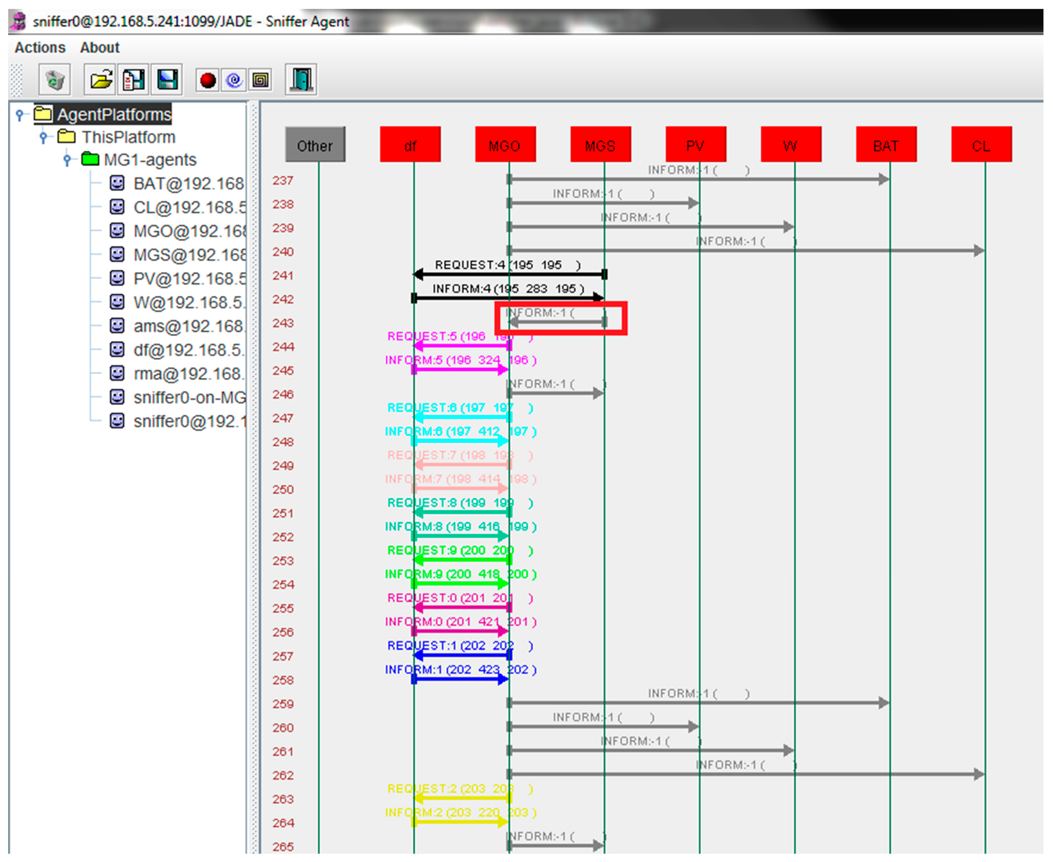
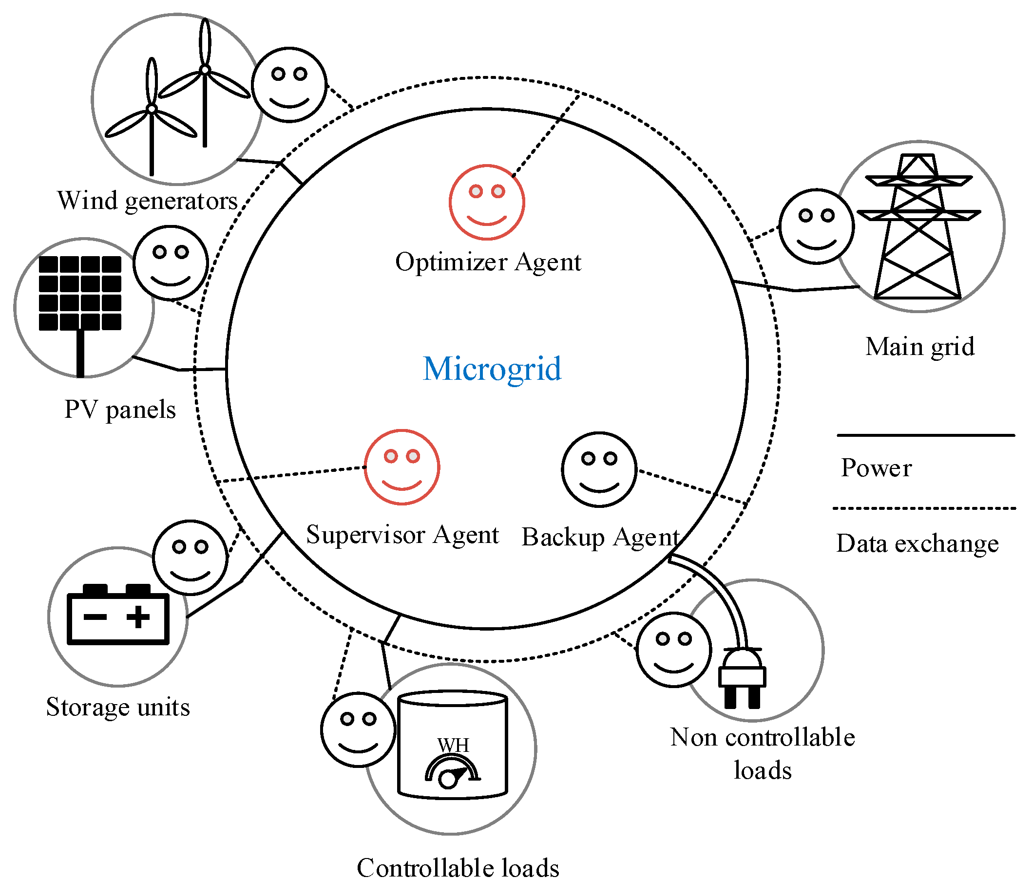
4. Proposed Multiagent EMS Platform

This section presents the MAS implemented for MG management and will present the developed agents and the proposed management strategy.
The agents are implemented in the Java Agent Development framework (JADE) platform. This platform respects the Foundation for Intelligent Physical Agents’ (FIPA) standards that are considered as the reference for MAS standards used by computer science developers’ community. JADE platform has the default Agent Management System (AMS) that controls the platform, creates and destroys other agents. The default Directory Facilitator (DF) is the agent responsible for registering all connected agents of the platform. Thus, if another agent wants to communicate with his peer, he has to ask the DF who will provide him with the name of the connected agent. In addition to these agents, the Agent Communication Channel also called the Message Transport System, is the agent in charge of transferring messages between agents of the platform [39]. JADE also provides graphical management service for platform management and control through the remote management agent (RMA). Any agent created in JADE is hosted in a container. This latter has all services for executing and hosting agents. Figure 2 presents the structure of the JADE platform, according to the FIPA agent management reference model.
The MG considered in this work is composed of wind generators, PV panels, storage units, controllable load, and non-controllable load. The MG is operating in grid-connected mode. Each one of these components has a specific agent. There are three agent categories: The management agents, backup agent, and communication agents.
The MAS implemented is illustrated in Figure 3.

4.1. Management Agents

The first category comprises agents that ensure the proper operation of the MG. The MG optimizer (MGO) is the agent responsible for running the optimization and ensuring the seamless operation of the MG in real time. The T-Cell algorithm is implemented in this agent. This agent gets the forecast data of the wind, PV, and load power and computes the references of each generation unit and controllable load at each time step 15 min. However, during this period, an unpredictable load variation can occur, which can jeopardize the MG operation. So, instead of running the optimization every few seconds which is resource consuming, this work presents a solution to implement a specific agent that checks continually if the load power has gone beyond permissible limits during the time step.
The MG supervisor (MGS) is the load supervisor agent. When the MGS intercepts sudden high load variations, it contacts the MGO that launches a new optimization cycle and computes the new optimum operating points of the generators and controllable loads.

4.2. Backup Agent

The Main Container (MC) is the special node which the agent platform relies on. It coordinates between the other nodes and hosts the AMS and the DF. Since this node is very critical, if it terminates or fails to connect to other containers, some vital operational features can become unavailable, and this severely hampers the platform [40]. In order to strengthen the agent platform and make it more reliable, a fault tolerant structure is implemented. It can be observed from Figure 4 that there are two MC in the agent platform. Replication support for MC has been introduced. Using this support, it is also possible to duplicate as many as MC in the system. These MC arrange themselves in a logical ring so that whenever one of them fails, the others will notice and act accordingly [18].

4.3. Interoperability Agents

The main function of interoperability agents is to ensure the communication between the MAS platform and the physical hardware. The communication is based on the data-centric publish-subscribe (DCPS) model.
There are two main distributed communication models that could be implemented in MG context: Data-centric communications and object-centric communication model. In data-centric communications, data distribution between communicating entities is the fundamental concept. This model is based on data publishers and data subscribers. Publishers pass data of known types to subscribers through a common channel. In the opposite, in object oriented communications, instead of focusing on the data, the main concern is the interface between entities. An interface comprises of a list of predefined methods ready to be used. An object oriented system is based on server and client interface communication. The client interface invokes methods on a named server interface, which the server responds accordingly [41]. Even though the two approaches are complementary, middleware built on data-centric communication are more competitive in the RT applications.
RTI DDS Connect was implemented as middleware for RT interoperability between the agent context and the hardware of the testbed. As explained earlier, data-centric communication is based on data sharing between publishers and subscribers. The RTI DDS Connext allows to user to create publishers and subscribers independently of the programming language. Publishers and subscribers are connected by ‘Topics.’ A Topic corresponds to a single data type that allows identifying which data is being to be shared between which publishers and subscribers [42]. For instance, if publisher A is publishing value ‘x’ in Topic 1, subscribers who want to get the ‘x’ value should connect to the same Topic 1.
In this work, a publisher for each generation units and controllable load were implemented in the MAS context. The MGO computes the references and sends them to the corresponding publisher agents. Once the data is published, the subscribers implemented in the SCADA system of the testbed read the data and operate accordingly. Figure 5 illustrates how the agents implemented in the agent context publish data in RTI DDS topics, and how each generation unit reads the published data through subscribers.

5. Results

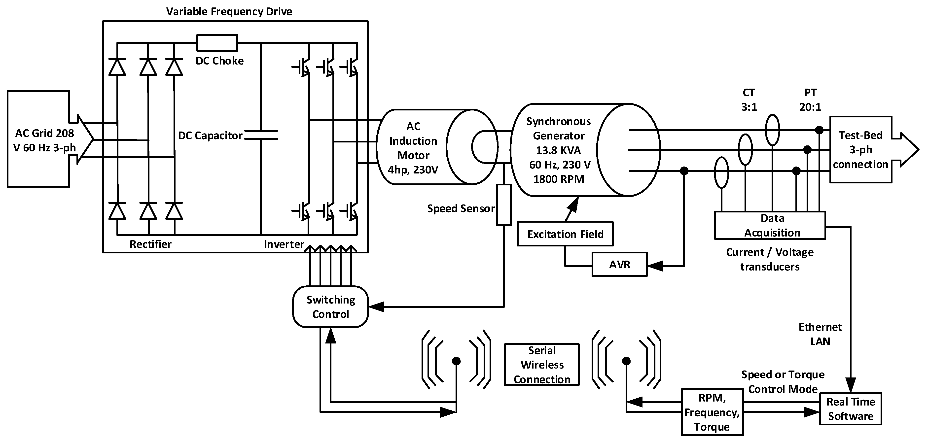
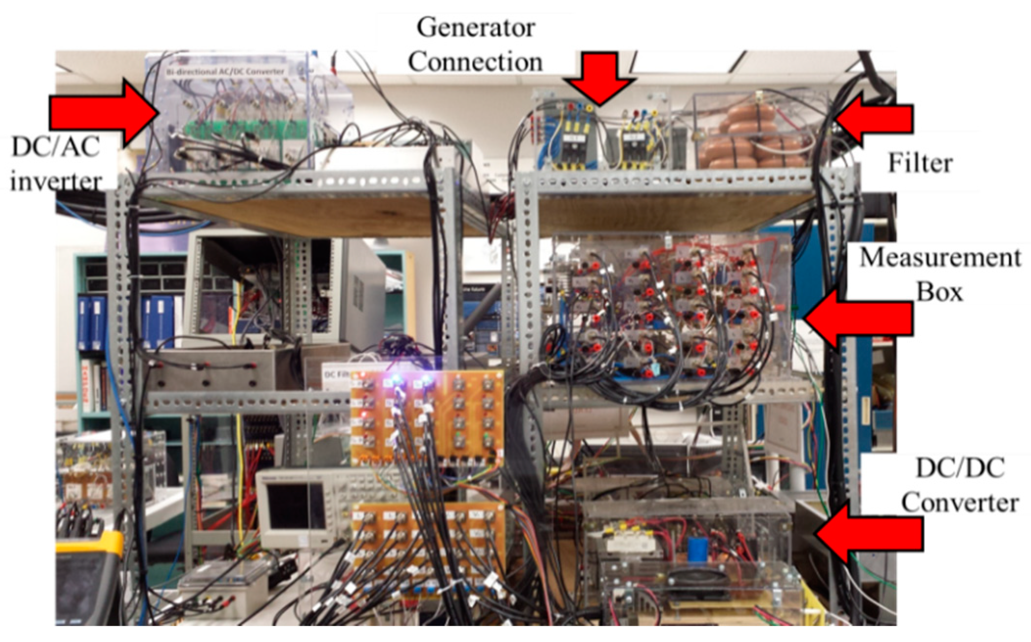
5.1. Description of the Cyber-Physical Setup

This section describes the implemented configuration of the testbed for the multi-agent RT-EMS experimentation in the Energy Systems Research Laboratory (ESRL), Florida International University.
The MG considered in this study is composed of a wind generator and PV system, each one is emulated by a synchronous generator, a storage unit emulated by a DC power supply, a controllable load, load, and connection to the grid.
Each generating station has five different types of motor drives, acting as five different prime movers to enable the implementation of various generation control strategies. These generators are equipped with frequency drives, Automatic Voltage Regulator (AVR) and synchronizer systems to control these different prime movers. The voltage regulators and automatic power control module controllers enable the system to operate as real-time generators. An automatic synchronizer connects each generator and controls the switching and measurement busses. The control and setup of each generation station are described in Figure 6.
The DC zone that emulates the DC storage unit is represented by a DC bus, where its voltage was set to 380 V and XR SERIES DC power supply offered by the MAGNA-POWER ELECTRONICS, which emulates the charging/discharging battery characteristics. It is interfaced with the DC bus through the DC-DC boost converter. The converter controllers are implemented in SIMULINK environment and executed in the DSpace 1104 real time interface. The system topology can be changed by using eight controlled switches. The switches have two states on and off. A control signal is sent to these switches to change their state which changes the equivalent circuit. The control is initiated from a virtual instrument (VI) program implemented in LabVIEW environment. The card PCI 6025E sends the control command to the circuit. This circuit is an inverting buffer module sn7406n of TEXAS INSTRUMENT. This module contains six inverters with open collector output. The RMS values for the voltage in the AC zone is set to 208 V. The AC bus is connected to the utility grid at PCC. Also, different load models were designed to represent the AC load pattern. Figure 7 shows the control of the power supply.
The testbed is controlled and monitored through the LabVIEW SCADA interface, as shown in Figure 8. The connected components for this experiment have switches with light green color.

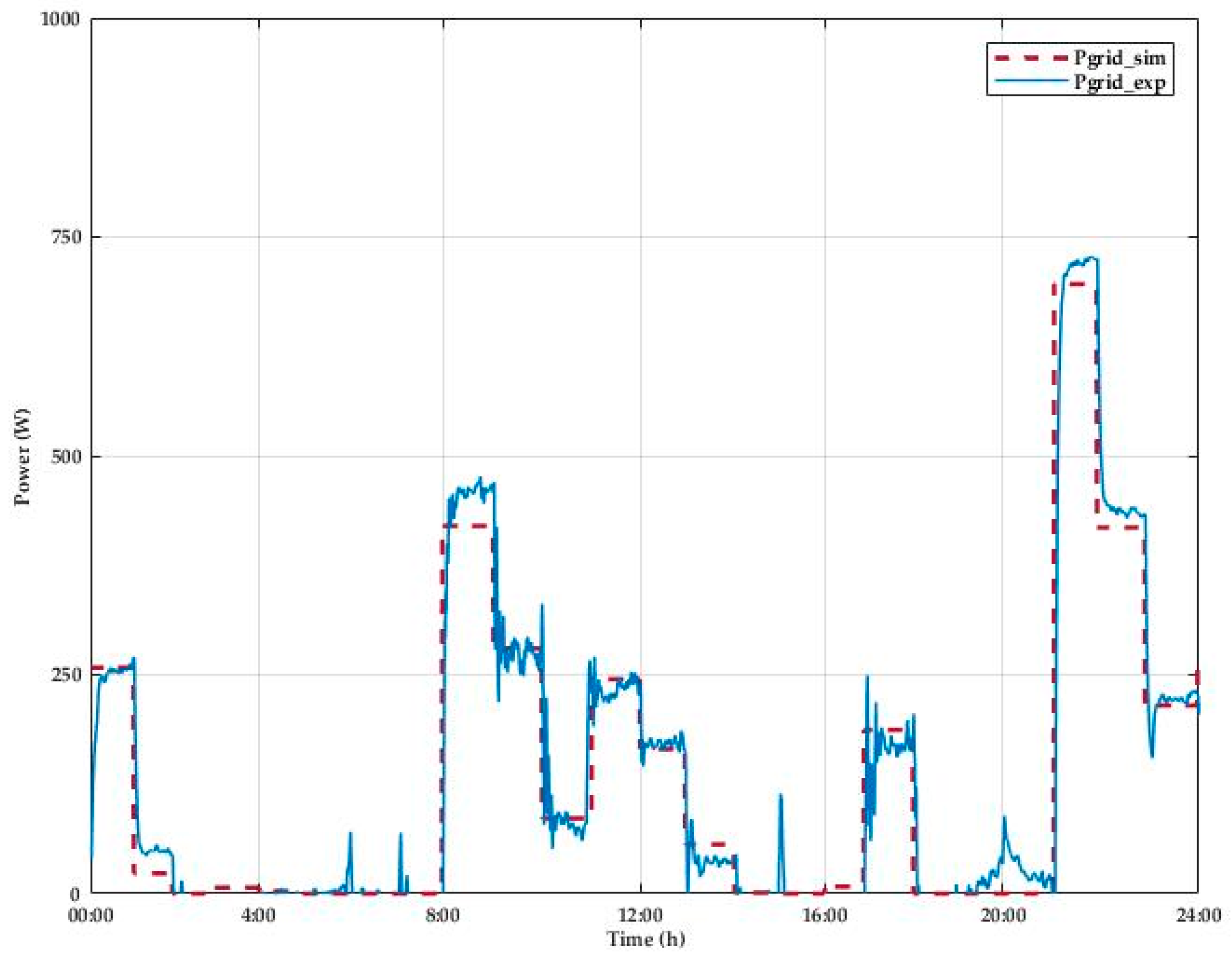
5.2. Experiment Results

This section presents the results obtained from simulation and experimentation of the multi-agent RT-EMS. Three case studies are considered. The first case study presents the implemented load supervision mechanism of the MAS. The second case study describes the operation of the fault tolerance mechanism in the MAS. The third case study compares the results of the experimentation and the simulation and presents the competitivity of the implemented RT-EMS in terms of time delay.

5.2.1. Case Study 1

This case study presents the implemented RT load supervision mechanism. The MGO conducts the optimization every 15 min based on the forecasted PV, wind, and load data. However, due to some exceptional event, the load value can occasionally make a high variation from the forecast value, which affects the stability of the MG operation. For this reason, the MGS was conceived to supervise the high load variation in RT. The MGS is a cyclic agent that executes every 2 s. It computes the variation between the RT load and the forecast values. When the computed difference exceeds 30%, the MGS sends a signal to the MGO to start another optimization cycle based on the new sensed load value.
Figure 9 shows the communication mechanism implemented in Jade platform between the MGO, MGS, and other publisher agents.
At line 241, the MGS detects a high variation of the load. Then, the MGS sends a request to DF agent to send him references of connected MGO. Once credentials are delivered, the MGS send to the MGO the signal to start a new optimization cycle in line 243. An optimization communication cycle starts from line 244 to line 262. The MGO at the beginning of each cycle sends the parameters of the current cycle to the MGS. Then, the MGO launches the optimization based on the T-Cell algorithm. At the end of the optimization, the computed references are sent to the publisher agents.

5.2.2. Case Study 2

This case study describes the implemented operation of the fault tolerance mechanism in the MAS. As explained in Section 3, the Main Container (MC) is a special node in the JADE platform that coordinates between other containers and agents hosted in these containers. In order to implement a fault-tolerant mechanism, a backup agent of the MC was created. The two main-containers are arranged in a unidirectional ring. The MC is considered as the master MC while the backup agent is considered as the slave. Once the master MC fails, the slave MC detects the failure and takes the appropriate recovery actions. Three containers were created in this case study. By default, the AMS and DF agents are affected to the master MC, which is the ‘Main-Container’ in our case. The ‘BackupContainer’ is created, and ‘Container-1’ hosts the MG agents. ‘Mg1’ is the MGO while other agents are the interoperability agents of each MG components. Figure 10 illustrates the MAS platform before and after the fault test. A manual failure event was introduced while the RT-EMS was running. Through the Jade user interface, the MC was terminated. Automatically and instantaneously, the backup agent detects the event, changes its status to the new master MC and transfers the AMS and DF from the faulty MC to its container. As a consequence, the list of all alive agents and containers in the multi-agent platform remain updated and the RT-EMS continues its normal operation.

5.2.3. Case Study 3

This case study compares the results of the conducted experimentation and the simulation of the RT-EMS and presents the performance of this system compared to previous work.
The experimental validation of the implemented T-Cell based RT-EMS developed in a MAS environment was tested in the Energy Systems Research Laboratory at Florida International University. Three different scenarios were taken into consideration to validate the efficiency and performance of the proposed algorithm:
  • Scenario 1: Normal operation of the MG. In this case, the system is running without sudden event. The MGO is computing and sending references of the generation units according to forecast data without any incident;
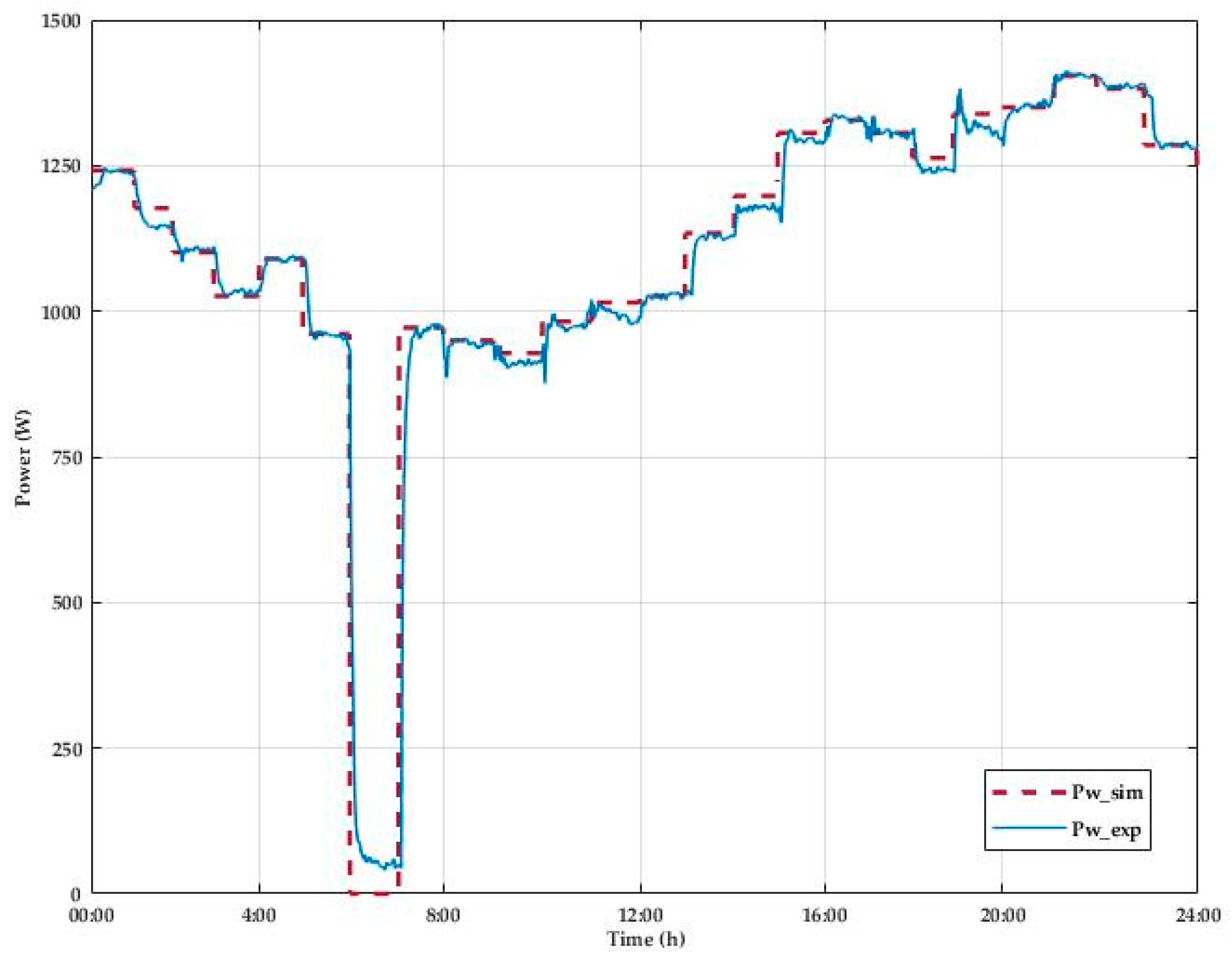
  • Scenario 2: Generation drop. This case tests the ability of the system to operate after a significant shift in power generation. For this matter, the wind generator has been shut down during the period 6:00–7:00;
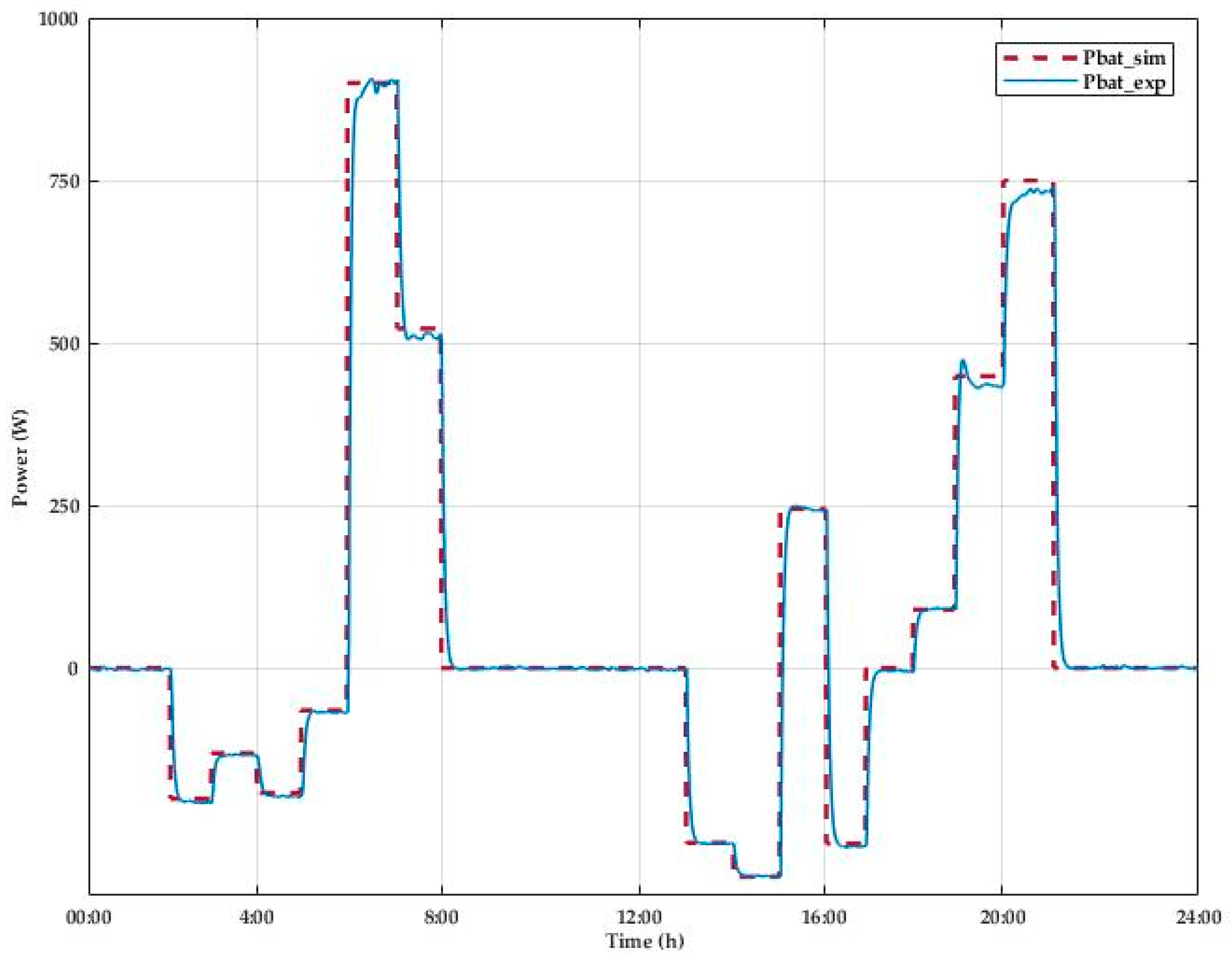
  • Scenario 3: Sudden load variation. This scenario challenges MG operation when there is a sudden load increase. It is reflected in the period 15:00–16:00, where the load increases from 1500 to 2400 W.
Table 1 presents the parameters of the considered system. It presents the interval values of each system variable. The energy storage is considered operating between 0.4 and 0.9 to protect the battery from the deep discharging and overcharging.
Figure 11 and Figure 12 illustrate the power profile of the wind and PV systems. As explained in Section 4.1, both wind and PV were emulated by two synchronous generators. It is noticeable from the two profiles that at the beginning of each period, there is a power fluctuation due to system transients. The power measured during the experiment is also slightly below simulated values because of the system losses. The wind generator was supposed shut down during the period 6:00–7:00 and the PV power profile was also assumed to be null before 7:00 and after 20:00; yet due to experimental constraints the generators were kept running at the minimum level. However, in Figure 13, Figure 14 and Figure 15, the experimental profile of the energy storage, the load and the controllable load matches the simulated values. The wind and PV profiles data used in this experiment are available in [43] and [44], respectively.
Figure 16 describes the power exchange with the grid. Unlike the PV and the wind emulators that receive the reference from EMS, the power exchange with the grid is automatically imported or injected depending on the system consumption and generation. For this reason, all system errors are compensated by the grid power which creates, in some cases, a mismatch between the experiment and simulation values. It also should be mentioned that the simulation shows the RMS value without any transient, but the experimental result demonstrates the actual values along with transient of the power system which includes the compensation within the generators, reactions and power grid losses.
Figure 17 illustrates the MG dynamic during a day of operation going through the three scenarios. From 00:00 to 2:00, the MG is supplying the load from the wind and the grid. As soon as the load decreases from 2:00 to 6:00, the proposed algorithm allows charging of the energy storage with the excess power. During the shutdown of the wind generator from 6:00 to 7:00, reflected by a drop of the wind power (scenario 2), the needed power was supported by the energy storage and the controllable load. The following day’s hours match more load increase, which is supplied by the grid, wind, controllable load, and the increasing PV power. From 13:00 to 15:00, the PV power is at the top generation, which allows charging the energy storage with excess power. Scenario 3 is tested from 15:00 to 16:00 in which the load suddenly raises from 1500 to 2400 W. The algorithm compensates the deficit power using the energy storage and controllable load. The MG continues its normal operation and uses the available power from the energy storage until it reaches its minimum value; then, the power needed is imported from the grid and the available wind power.
Through the 24 h of operation in different scenarios, the proposed T-cell based RT-EMS has proven his effectiveness and capability of maintaining the stability and balance of the MG.
The proposed T-Cell algorithm that has been implemented for the EMS optimization is coded in Java language using the Eclipse programming environment. The environment integrates the JADE tool kit and the DDS interoperability agents. Before implementing those agents, it is important to define the data model for the MG. In our case, the data model consists of four variables of type double that represents the reference computed by the MGO. These four variables are published through the DDS agents into four topics, as illustrated in Figure 18. In the other side, the LabVIEW SCADA system implements the subscribers for these topics. Once the new data is published, it is automatically intercepted by the subscribers and sent to the appropriate generator or controllable load.
The RT-EMS has been tested using a computer with the following specifications: 4GB of RAM and 2 GHz of CPU. In this configuration, the average execution time of the T-Cell algorithm is 231 ms. However, when executed in a computer of 6G of RAM, the average execution time is 60 ms. In both cases, the T-Cell algorithm presented better performance than mixed integer nonlinear programming (MINLP) and multi-period artificial bee colony algorithm (MABC) that have 8.23 s and 1.14 s respectively [10].
The execution time is very crucial for RT-EMS in MG context and not as important as in day ahead management where the optimization is run a day before. The notion of real time that has been reported in different papers is between 3 to 5 min. The reason behind choosing this time is because it is less than the time needed for the adjustment of protective relay such as over/under voltage relay. Besides, PV systems and wind generators usually need more than 5 s to be affected by atmospheric variations. Although the implemented RT-EMS could be executed every 5 min and still presents better results than previous works, it is executed every 15 min. The main reason is that the system has the MGS, which is continually checking for high load variation and in this case, launches a new optimization cycle. This way, system resources are used optimally. The MG under study has an RS232 serial connection network for the control of the testbed components and the SCADA system, as illustrated in Figure 5. The latency time for sending data from the LabVIEW SCADA system to the generators and controllable loads in the testbed is 1 s [45].
Furthermore, for a measurement message size of 32 bytes and message rate of 1000 Msg/s, the average latency for DDS middleware is 243 µs with 90% below 269 µs [46]. The T-Cell optimization algorithm executed in a computer of 4GB of RAM and 2 GHz of CPU has an average latency of 231 ms. Therefore, the total latency of the RT-EMS is 1.3 s on average, which is way less than the 3 min presented in [10].
Another positive point could be stated. As the MG size increases and additional components are connected, the system variables will increase. This would be reflected in the execution time that would increase too. However, the proposed immune algorithm was tested along with fast, chaotic particle swarm optimization (PSO) and independent component analysis based PSO in the case of the small and medium power network, and the T-Cell algorithm reached a better optimum in minimum time [15].

5.3. Discussion

The proposed RT-EMS has several features that make it easy to implement in MGs as well as in smart buildings. The MAS makes it easier to extend the system and add other components. New agents can be designed for new components and integrated in the agent platform and then added in the optimization system. In addition, the DDS makes it very easy to integrate any type of hardware to the existing MG. For instance, a new PV system in a smart building, can interfaced to the SCADA using a new publisher and a new topic for this new PV system. Thus, the RT-EMS is modular and easy to extend for larger MGs.
Nevertheless, the system can be improved by considering the distribution losses and constraints in the optimization. Since the present work focuses on small scale MGs e.g., smart home, where all generations and consumption units are in the same location, the losses are not significant; for this reason, this assumption was made. However, one of the future improvements of the present work is to take it into consideration. The authors considered the water heater as a controllable load as it can be easily turn on and off without affecting costumer comfort. Besides, the relatively small size of the controllable power used in this work make it comparable to a water heater. However, in a large Mg, the controllable loads could be considered as the centralized air conditioner, the washing machine or dishwasher which present a bigger power to control. A second optimization layer between MGOs that negotiate the best option for buying or selling the power depending on the market prices could be added. Besides, the grid connected mode was considered in this study. Future works can consider the islanded mode of operation that updates the RT-EMS parameters accordingly.

6. Conclusions

Smart cities are no longer a future vision but a reality. Technologies are not only shaping our modern life but also helping us to preserve the environment and adopt a more sustainable life. Several cities around the world launch programs aiming to preserve the environment. While some cities choose to promote the use of applications to ease the city traffic and therefore reduce gas emissions, others present incentives to its citizens to produce renewable energy and reduce their consumption during peak hours; In this context, developing a comprehensive EMS that would enhance cities sustainability agenda is a hot topic. Our proposed solution that incorporate fast real time optimization would be a good asset for sustainable cities. A multiagent RT-EMS based on T-Cell algorithm was implemented and successfully experimented in the smart grid testbed at Florida International University for optimally managing a MG. Three scenarios were tested to show the effectiveness and optimal operation of the MG using the proposed technique. Comparison of simulations and experimental results show the ability of the proposed multiagent T-Cell based RT-EMS in maintaining the stability and smooth operation of the MG. In addition, the modularity and fault tolerance features were easier to implement through the MAS JADE platform. The DDS middleware also allows the interoperability between different components of the system. The results obtained by the multiagent RT-EMS highlight the effectiveness of the proposed algorithm and demonstrate a faster convergence time compared to previous works. The optimum values were obtained faster in terms of computation time as compared to existing techniques. The latency from the proposed system was 43% faster than other heuristic or deterministic methods in the literature. This significant improvement makes this proposed system more competitive for RT applications. Therefore, our proposed EMS could be envisioned as a real solution for future RT operating MG. Furthermore, this EMS could also be implemented in smart homes or smart buildings that integrate RE and need RT EMS. Through the use of RT-EMS, the MG operator not only guaranties reduction of energy consumption cost, but also, assure the maximum utilization of available RE. As a consequence, the system is more resilient and participate in reducing the negative environmental impact. The RT-EMS also apply DR when needed, which have a positive impact on the distribution system during peak hours.

Author Contributions

F.Z.H. conceived, implemented the software and wrote the original draft. A.F.E. and M.M.E. contributed to the experimental, review and editing work. N.K. is the responsible for funding acquisition and contributed to work investigation and supervision. N.H. contributed with materials tools and supervision. O.A.M. is the supervisor who leads the project and edits the manuscript and he is the corresponding author.

Funding

This research was funded by IRESEN in the framework of the Inno-PV research project “SECRETS—Sustainable Energy Clusters Realized Through Smart Grids” and the Fulbright Join Supervision program.

Acknowledgments

This work was supported by Energy Systems Research Laboratory, Department of Electrical and Computer Engineering, Florida International University, Miami, Florida USA.

Conflicts of Interest

The authors declare no conflict of interest.

References

  1. Margoum, E.H.; Krami, N.; Harmouch, F.Z.; Al montaser, H.; Seca, L.; Moreira, C. Design and Control of Single Phase Photovoltaic Systems for AC MicroGrid. In Proceedings of the 2016 International Renewable and Sustainable Energy Conference (IRSEC), Marrakech, Morocco, 14–17 November 2016; pp. 1188–1193. [Google Scholar] [CrossRef]
  2. Margoum, E.H.; Krami, N.; Seca, L.; Moreira, C.; Mharzi, H. Design and Control of Parallel Three Phase Voltage Source Inverters in Low Voltage AC Microgrid. Adv. Electr. Electron. Eng. 2017, 15, 120–129. [Google Scholar] [CrossRef]
  3. Jebaraj, L.; Venkatesan, C.; Soubache, I.; Rajan, C.C.A. Application of Differential Evolution Algorithm in Static and Dynamic Economic or Emission Dispatch Problem: A Review. Renew. Sustain. Energy Rev. 2017, 77, 1206–1220. [Google Scholar] [CrossRef]
  4. Dieu, V.N.; Ongsakul, W.; Polprasert, J. The Augmented Lagrange Hopfield Network for Economic Dispatch with Multiple Fuel Options. Math. Comput. Model. 2013, 57, 30–39. [Google Scholar] [CrossRef]
  5. Secui, D.C. Large-Scale Multi-Area Economic/Emission Dispatch Based on a New Symbiotic Organisms Search Algorithm. Energy Convers. Manag. 2017, 154, 203–223. [Google Scholar] [CrossRef]
  6. Tade, S.V.; Ghate, V.N.; Mulla, S.Q.; Kalgunde, M.N. Application of Dynamic Programming Algorithm for Thermal Unit Commitment with Wind Power. In Proceedings of the 2018 IEEE Global Conference on Wireless Computing and Networking, GCWCN, Lonavala, India, 23–24 November 2018; pp. 182–186. [Google Scholar] [CrossRef]
  7. Mohsen, N.; Braun, M.; Tenbohlen, S. Optimization of Unit Commitment and Economic Dispatch in Microgrids Based on Genetic Algorithm and Mixed Integer Linear Programming. Appl. Energy 2018, 210, 944–963. [Google Scholar]
  8. Moghaddam, M.M.; Marzband, M.; Azarinejadian, F. Optimal Energy Management for a Home Microgrid Based on Multi-Period Artificial Bee Colony. In Proceedings of the 25th Iranian Conference on Electrical Engineering (lCEE2017), Tehran, Iran, 2–4 May 2017; pp. 1446–1451. [Google Scholar]
  9. Shi, W.; Li, N.; Chu, C.-C.; Gadh, R. Real-Time Energy Management in Microgrids. IEEE Trans. Smart Grid 2017, 8, 228–238. [Google Scholar] [CrossRef]
  10. Marzband, M.; Ghazimirsaeid, S.S.; Uppal, H.; Fernando, T. A Real-Time Evaluation of Energy Management Systems for Smart Hybrid Home Microgrids. Electr. Power Syst. Res. 2017, 143, 624–633. [Google Scholar] [CrossRef]
  11. Netto, R.S.; Ramalho, G.R.; Bonatto, B.D.; Carpinteiro, O.A.S.; Zambroni De Souza, A.C.; Oliveira, D.Q.; Braga, R.A.S. Real-Time Framework for Energy Management System of a Smart Microgrid Using Multiagent Systems. Energies 2018, 11, 656. [Google Scholar] [CrossRef]
  12. Aragon, V.S.; Esquivel, S.C.; Coello Coello, C.A. Optimizing Constrained Problems through a T-Cell Artificial Immune System. J. Comput. Sci. Technol. 2008, 8, 158–165. [Google Scholar]
  13. Alberts, B.; Johnson, A.; Lewis, J.; Raff, M.; Roberts, K.; Walter, P. Helper T Cells and Lymphocyte Activation. In Molecular Biology of the Cell; Garland Science: New York, NY, USA, 2002. [Google Scholar]
  14. Aragon, V.S.; Esquivel, S.C.; Coello Coello, C.A. A T-Cell Algorithm for Solving Dynamic Optimization Problems. Inf. Sci. 2011, 181, 3614–3637. [Google Scholar] [CrossRef]
  15. Aragón, V.S.; Esquivel, S.C.; Coello Coello, C.A. An Immune Algorithm with Power Redistribution for Solving Economic Dispatch Problems. Inf. Sci. 2015, 295, 609–632. [Google Scholar] [CrossRef]
  16. Harmouch, F.Z.; Krami, N.; Benhaddou, D.; Hmina, N.; Zayer, E.; Margoum, E.H. Survey of Multiagents Systems Application in Microgrids. In Proceedings of the 2nd International Conference on Electrical and Information Technologies ICEIT’2016, Tangier, Morocco, 4–7 May 2016; pp. 270–275. [Google Scholar]
  17. Mcarthur, S.D.J.; Davidson, E.M.; Catterson, V.M.; Dimeas, A.L.; Hatziargyriou, N.D.; Ponci, F.; Funabashi, T. Multi-Agent Systems for Power Engineering Applications—Part I : Concepts, Approaches, and Technical Challenges. IEEE Trans. Power Syst. 2007, 22, 1743–1752. [Google Scholar] [CrossRef]
  18. Harmouch, F.Z.; Krami, N.; Hmina, N. A Multiagent Based Decentralized Energy Management System for Power Exchange Minimization in Microgrid Cluster. Sustain. Cities Soc. 2018, 40, 416–427. [Google Scholar] [CrossRef]
  19. Pinto, T.; Ghazvini, M.A.F.; Soares, J.; Faia, R.; Corchado, J.M.; Castro, R.; Vale, Z. Decision Support for Negotiations among Microgrids Using a Multiagent Architecture. Energies 2018, 11, 2526. [Google Scholar] [CrossRef]
  20. Cintuglu, M.H.; Martin, H.; Mohammed, O.A. Real-Time Implementation of Multiagent-Based Game Theory Reverse Auction Model for Microgrid Market Operation. IEEE Trans. Smart Grid 2015, 6, 1064–1072. [Google Scholar] [CrossRef]
  21. Mahmoudian Esfahani, M.; Hariri, A.; Mohammed, O.A. A Multiagent-Based Game-Theoretic and Optimization Approach for Market Operation of Multi-Microgrid Systems. IEEE Trans. Ind. Inform. 2018, 3203, 1–12. [Google Scholar] [CrossRef]
  22. Logenthiran, T.; Srinivasan, D.; Khambadkone, A.M. Multi-Agent System for Energy Resource Scheduling of Integrated Microgrids in a Distributed System. Electr. Power Syst. Res. 2011, 81, 138–148. [Google Scholar] [CrossRef]
  23. Pinto, T.; Faia, R.; Navarro-Caceres, M.; Santos, G.; Corchado, J.M.; Vale, Z. Multi-Agent-Based CBR Recommender System for Intelligent Energy Management in Buildings. IEEE Syst. J. 2019, 13, 1084–1095. [Google Scholar] [CrossRef]
  24. Anvari-Moghaddam, A.; Rahimi-Kian, A.; Mirian, M.S.; Guerrero, J.M. A Multi-Agent Based Energy Management Solution for Integrated Buildings and Microgrid System. Appl. Energy 2017, 203, 41–56. [Google Scholar] [CrossRef]
  25. Bui, V.; Hussain, A.; Kim, H. Optimal Operation of Microgrids Considering Auto-Configuration Function Using Multiagent System. Energies 2017, 10, 1484. [Google Scholar] [CrossRef]
  26. Choi, I.S.; Hussain, A.; Bui, V.H.; Kim, H.M. A Multi-Agent System-Based Approach for Optimal Operation of Building Microgrids with Rooftop Greenhouse. Energies 2018, 11, 1876. [Google Scholar] [CrossRef]
  27. Gómez-Expósito, A.; Conejo, J.A.; Cañizares, C. Electric Energy Systems Analysis and Operation; CRC Press: Boca Raton, FL, USA, 2009. [Google Scholar]
  28. Marzband, M.; Ghadimi, M.; Sumper, A.; Domínguez-garcía, J.L. Experimental Validation of a Real-Time Energy Management System Using Multi-Period Gravitational Search Algorithm for Microgrids in Islanded Mode. Appl. Energy 2014, 128, 164–174. [Google Scholar] [CrossRef]
  29. Xiaoping, L.; Ming, D.; Jianghong, H.; Pingping, H.; Yali, P. Dynamic Economic Dispatch for Microgrids Including Battery Energy Storage. IEEE Int. Symp. Power Electron. Distrib. Gener. Syst. 2010, 2, 914–917. [Google Scholar] [CrossRef]
  30. Marzband, M.; Parhizi, N.; Savaghebi, M.; Guerrero, J.M. Distributed Smart Decision-Making for a Multimicrogrid System Based on a Hierarchical Interactive Architecture. IEEE Trans. Energy Convers. 2016, 31, 637–648. [Google Scholar] [CrossRef]
  31. Ross, D.; Kim, S. Dynamic Economic Dispatch of Generation. IEEE Trans. Power Appar. Syst. 1980, 99, 2060–2068. [Google Scholar] [CrossRef]
  32. Liang, Z.X.; Glover, J.D. A Zoom Feature for a Dynamic Programming Solution to Economic Dispatch Including Transmission Losses. IEEE Trans. Power Syst. 1992, 7, 544–550. [Google Scholar] [CrossRef]
  33. Hemamalini, S.; Simon, S.P. Dynamic Economic Dispatch Using Maclaurin Series Based Lagrangian Method. Energy Convers. Manag. 2010, 51, 2212–2219. [Google Scholar] [CrossRef]
  34. Li, Z.; Wu, W.; Zhang, B.; Sun, H.; Guo, Q. Dynamic Economic Dispatch Using Lagrangian Relaxation With Multiplier Updates Based on a Quasi-Newton Method. IEEE Trans. Power Syst. 2013, 28, 4516–4527. [Google Scholar] [CrossRef]
  35. Shilaja, C.; Ravi, K. Optimization of Emission/Economic Dispatch Using Euclidean Affine Flower Pollination Algorithm (EFPA) and Binary FPA (BFPA) in Solar Photo Voltaic Generation. Renew. Energy 2017, 107, 550–566. [Google Scholar] [CrossRef]
  36. Chen, C.; Duan, S.; Cai, T.; Liu, B.; Hu, G. Smart Energy Management System for Optimal Microgrid Economic Operation. IET Renew. Power Gener. 2011, 5, 258. [Google Scholar] [CrossRef]
  37. Faia, R.; Pinto, T.; Vale, Z.; Corchado, J.M.; Soares, J.; Lezama, F. Genetic Algorithms for Portfolio Optimization with Weighted Sum Approach. In Proceedings of the 2018 IEEE Symposium Series on Computational Intelligence, Bangalore, India, 18–21 Novermber 2018; pp. 1823–1829. [Google Scholar] [CrossRef]
  38. Oliveira, D.Q.; Zambroni de Souza, A.C.; Almeida, A.B.; Lima, I. An Artificial Immune Approach for Service Restoration in Smart Distribution Systems. In Proceedings of the 2015 IEEE PES Innovative Smart Grid Technologies Latin America (ISGT LATAM), Montevideo, Uruguay, 5–7 October 2015; pp. 1–6. [Google Scholar]
  39. Bellifemine, F.; Caire, G.; Greenwood, D. Developing Multi-Agent with JADE Systems; Wooldridge, M., Ed.; John Wiley & Sons: London, UK, 2007. [Google Scholar] [CrossRef]
  40. Bellifemine, F.; Caire, G.; Trucco, T.; Rimassa, G.; Mungenast, R. JADE Administrator’s Guide; TILab: Turin, Italy, 2010. [Google Scholar]
  41. RTI DDS. What Is DCPS? Available online: https://community.rti.com/static/documentation/connext-dds/5.2.0/doc/manuals/connext_dds/html_files/RTI_ConnextDDS_CoreLibraries_UsersManual/Content/UsersManual/What_is_DCPS_.htm (accessed on 15 June 2019).
  42. RTI DDS. Data Topics—What Is the Data Called? Available online: https://community.rti.com/static/documentation/connext-dds/5.2.0/doc/manuals/connext_dds/html_files/RTI_ConnextDDS_CoreLibraries_UsersManual/index.htm#UsersManual/Data_Topics___What_is_the_Data_Called_.htm%3FTocPath%3DPart%25201%253A%2520Introduction%7CDa (accessed on 15 June 2019).
  43. The Pennsylvania State Climatologist. 2018. Available online: http://climate.psu.edu/ (accessed on 22 June 2019).
  44. National Solar Radiation Data Base. 1991. Available online: https://rredc.nrel.gov/solar/old_data/nsrdb/1991-2010/hourly/siteonthefly.cgi?id=722020 (accessed on 22 June 2019).
  45. Salehi, V.; Mohamed, A.; Member, S.; Mazloomzadeh, A.; Mohammed, O.A. Laboratory-Based Smart Power System, Part I : Design and System Development. IEEE Trans. Smart Grid 2012, 3, 1394–1404. [Google Scholar] [CrossRef]
  46. Youssef, T.A.; Elsayed, A.T.; Mohammed, O.A. Data Distribution Service-Based Interoperability Framework for Smart Grid Testbed Infrastructure. Energies 2016, 9, 150. [Google Scholar] [CrossRef]
Figure 1. T-Cell algorithm process.
Energies 12 03004 g001
Figure 2. Jade platform architecture.
Energies 12 03004 g002
Figure 3. MAS architecture.
Energies 12 03004 g003
Figure 4. The fault tolerance mechanism in MAS platform.
Energies 12 03004 g004
Figure 5. Interoperability Communication Setup.
Energies 12 03004 g005
Figure 6. Generation station hardware and control.
Energies 12 03004 g006
Figure 7. Control of DC power supply.
Energies 12 03004 g007
Figure 8. SCADA interface in ESRL.
Energies 12 03004 g008
Figure 9. Communication between MGO, MGS and other agents.
Energies 12 03004 g009
Figure 10. Fault tolerance mechanism in the JADE platform.
Energies 12 03004 g010
Figure 11. Comparison between simulated output and testbed measured values of wind power.
Energies 12 03004 g011
Figure 12. Comparison between simulated output and testbed measured values of PV power.
Energies 12 03004 g012
Figure 13. Comparison between simulated output and testbed measured values of energy storage power.
Energies 12 03004 g013
Figure 14. Comparison between simulated output and testbed measured values of load power.
Energies 12 03004 g014
Figure 15. Comparison between simulated output and testbed measured values of controllable load.
Energies 12 03004 g015
Figure 16. Comparison between simulated output and testbed measured values of grid power.
Energies 12 03004 g016
Figure 17. Experimental results of the MG powers during 24 h operation.
Energies 12 03004 g017
Figure 18. DDS Connext view.
Energies 12 03004 g018
Table 1. Microgrid parameters.
VariableMeaning of the VariableLimit Values
PpvThe predicted power generation of the PV system0 W ≤ Ppv ≤ 700 W
PwThe predicted power generation of the wind turbine0 W ≤ Pw ≤ 1500 W
PbatThe predicted charging or discharging power of the battery−1500 W ≤ Pbat ≤ 1500 W
SOCState of charge of the battery0.2 ≤ SOC ≤ 0.9
PlActive power load0 W ≤ Pl ≤ 2700 W
PclControllable loadPcl = 0.2 Pl

