Article

Current Control of the Permanent-Magnet Synchronous Generator Using Interval Type-2 T-S Fuzzy Systems

Department of Electrical Engineering and Advanced Institute of Manufacturing with High-tech Innovations, National Chung Cheng University, Chiayi 62102, Taiwan
*
Author to whom correspondence should be addressed.
Energies 2019, 12(15), 2953; https://doi.org/10.3390/en12152953
Submission received: 10 July 2019 / Revised: 25 July 2019 / Accepted: 29 July 2019 / Published: 31 July 2019
(This article belongs to the Special Issue Selected Papers from IEEE ICKII 2019)

Abstract

:
The current control of the permanent-magnet synchronous generator (PMSG) using an interval type-2 (IT2) Takagi-Sugeno (T-S) fuzzy systems is designed and implemented. PMSG is an energy conversion unit widely used in wind energy generation systems and energy storage systems. Its performance is determined by the current control approach. IT2 T-S fuzzy systems are implemented to deal with the nonlinearity of a PMSG system in this paper. First, the IT2 T-S fuzzy model of a PMSG is obtained. Second, the IT2 T-S fuzzy controller is designed based on the concept of parallel distributed compensation (PDC). Next, the stability analysis can be conducted through the Lyapunov theorem. Accordingly, the stability conditions of the closed-loop system are expressed in Linear Matrix Inequality (LMI) form. The AC power from a PMSG is converted to DC power via a three-phase six-switch full bridge converter. The six-switch full bridge converter is controlled by the proposed IT2 T-S fuzzy controller. The analog-to-digital (ADC) conversion, rotor position calculation and duty ratio determination are digitally accomplished by the microcontroller. Finally, simulation and experimental results verify the performance of the proposed current control.

1. Introduction

A permanent-magnet synchronous generator (PMSG) [1] is an essential unit implemented to convert energy. Its power density and power conversion efficiency is high and its maintenance cost is low. Consequently, PMSG can be implemented in various utilizations like electric vehicles (EV) and hybrid electric vehicles (HEV) [2,3], home appliances [4], wind generation systems [5], flywheel energy storage systems (FESS) [6] and ultrahigh-speed elevators [7]. The embedded type of the permanent magnet will affect the characteristics of a PMSG. The interior-type [8,9,10] has high inductance saliency and generates higher torque. However, its torque ripple is also higher. On the contrary, the torque ripple of the surface-mounted type [10,11] is lower and its reluctance torque is nearly absent [12]. In motor design concept, magnet design methods [13,14] are presented to optimize the performance and minimize the torque ripple.
If the d-axis current is controlled at zero, then the electromagnetic torque of a PMSG is proportional to the q-axis current. This characteristic enhances the importance of current controls [15,16,17,18,19,20] for the PMSG. Since the power generating performance of a PMSG is affected by its winding current, the torque ripple can be eliminated by reducing winding current harmonics [16]. Moreover, the generating capability of a PMSG can be improved via adopting proper and good current control algorithms. The traditionally implemented current control schemes include fixed-frequency control [17,18], hysteresis control [19] and predictive control [20]. The state space equation of a PMSG is nonlinear. Therefore, the Takagi-Sugeno fuzzy [21,22] (T-S fuzzy) system is implemented to design a speed controller for the permanent-magnet synchronous motor (PMSM) and a current controller for the PMSG. System uncertainty [23] generally exists in nonlinear systems. Therefore, the interval type-2 (IT2) fuzzy logic system [24,25] is proposed to deal with this problem. In this paper, IT2 T-S fuzzy models are implemented in the design of a current controller for the PMSG.
In this study, system configuration of the PMSG is first introduced. Then the dynamic model of a PMSG is conducted. Next, IT2 T-S fuzzy models of a PMSG are established for the design of an IT2 T-S fuzzy current controller. The stability of the IT2 T-S fuzzy control system for PMSG is analyzed using the Lyapunov theorem. The stability conditions of the proposed current controller are expressed in Linear Matrix Inequality (LMI) form. Experimental results, including constant current command tracking, variable current command tracking and computation time of the microcontroller, are demonstrated to verify the performance of the designed IT2 T-S fuzzy current controller.

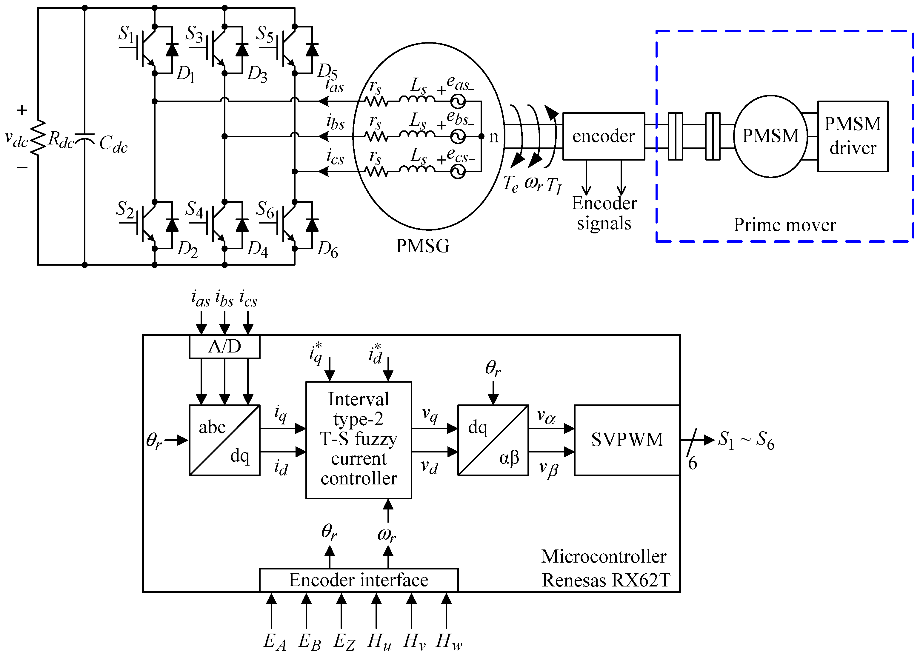
2. System Configuration and Dynamic Model

Figure 1 introduces the system configuration of the PMSG based on the IT2 T-S fuzzy control systems. The prime mover of the PMSG consists of a PMSM with a PMSM driver. The input torque of PMSG is provided by the prime mover. The encoder signals on the shaft are utilized to calculate rotor speed and rotor position. Three-phase winding currents are sensed through the analog-to-digital converter (ADC). Then the abc-frame currents are transformed to dq-frame currents. The current commands and dq-frame currents are implemented in the IT2 T-S fuzzy current controller to calculate the dq-frame voltage commands. The corresponding duty ratio of six switches is determined via space-vector pulse-width modulation (SVPWM). All the control and transformation schemes are digitally realized using the microcontroller Renesas RX62T (Renesas Electronics Corp., Tokyo, Japan).
For convenience, voltage equations of the PMSG are expressed in dq-frame [1]:
v q = r s i q L q i ˙ q ω r L d i d + ω r λ m v d = r s i d L d i ˙ d + ω r L q i q
where vd and vq are dq-frame voltages, id and iq are dq-frame currents, rs is winding resistance, Ld and Lq are dq-frame inductances, ω r is electrical rotor speed and λ m is the flux linkage established by the permanent magnet.
A PMSG can produce electromagnetic torque as follows:
T e = ( 3 2 ) ( P 2 ) [ λ m i q + ( L q L d ) i q i d ] .
The electromagnetic torque is related to electrical rotor speed in the mechanical equation:
T e = J ( 2 P ) ω ˙ r B ( 2 P ) ω r + T I
where J is the inertia of a PMSG, B is the damping coefficient of a PMSG, T I is the input torque and P is magnetic pole number.
If i d = 0 is satisfied in Equation (2), then the state equations of a PMSG are obtained:
i ˙ q = 1 L s ( v q r s i q ω r L s i d + ω r λ m ) i ˙ d = 1 L s ( v d r s i d + ω r L s i q ) ω ˙ r = 1 J [ ( P 2 ) ( T I T e ) B ω r ] = ( 3 P 2 8 J λ m i q B J ω r + P 2 J T I )

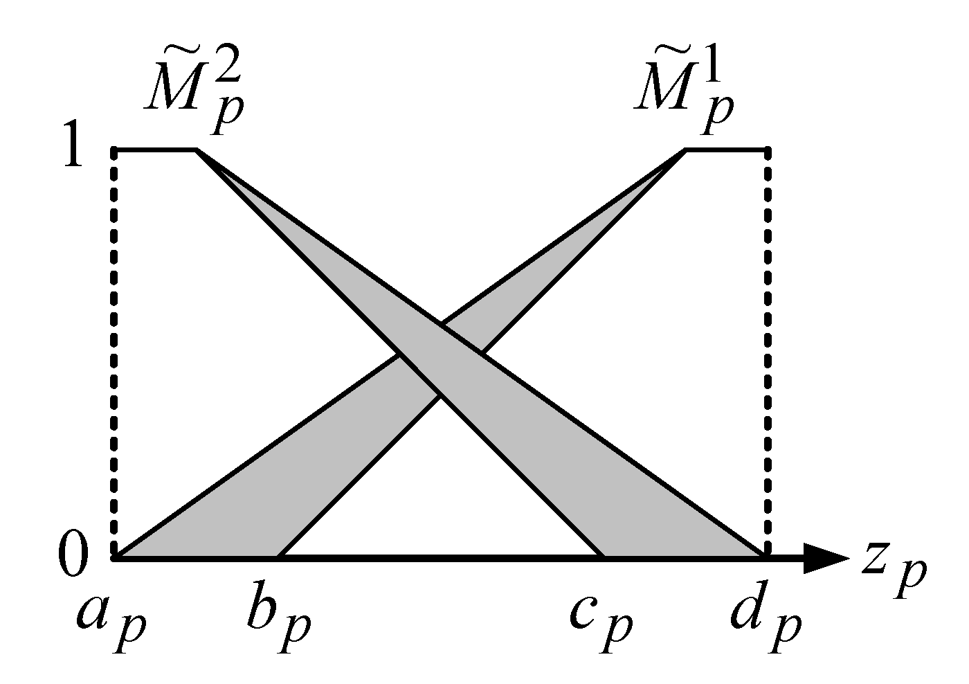
3. Design of the IT2 T-S Fuzzy Current Controller

Two new state variables are defined to guarantee current tracking capability:
s 1 = [ r 1 i q ] d t s 2 = [ r 2 i d ] d t s ˙ 1 = r 1 i q s ˙ 2 = r 2 i d
where r 1 is the target value of i q and r 2 is target value of i d .
Extended state equations of the PMSG are obtained by combing Equations (4) and (5):
[ ω ˙ r i ˙ q i ˙ d s ˙ 1 s ˙ 1 ] = [ B J 3 P 2 λ m 8 J 0 0 0 λ m L q r s L q L d L q ω r 0 0 L q L d i q 0 r s L d 0 0 0 1 0 0 0 0 0 1 0 0 ] [ ω r i q i d s 1 s 2 ] + [ 0 1 L q 0 0 0 0 0 1 L d 0 0 ] [ v q v d ] + [ P T I 2 J 0 0 r 1 r 2 ]
x ˙ ( t ) = A x ( t ) + B u ( t ) + E v ( t )
where v ( t ) represent disturbances in PMSG systems.
The required output function is:
y ( t ) = [ 0 1 0 0 0 0 0 1 0 0 ] [ ω r i q i d s 1 s 2 ] = C x ( t ) .
The IT2 T-S fuzzy models and IT2 T-S fuzzy controller are combined to form the IT2 T-S fuzzy control systems. The characteristics of IT2 T-S fuzzy control systems employ the upper membership function and lower membership function to represent the model uncertainty of a nonlinear system. In the nonlinear system matrix of the PMSG, state variables i q and ω r are found. Therefore, i q and ω r are selected as Antecedent z 1 and z 2 , respectively. The membership function of the IT2 T-S fuzzy is shown in Figure 2. z p is the Antecedent variable. a p , b p , c p and d p are the boundaries of the upper and lower membership functions. In the developed PMSG system, the rating of i q is 18A and the rating of ω r is 754 rad/sec. In order to represent the model uncertainty of the PMSG system, 5% variation of the Antecedent variable is selected. Therefore, the Antecedent variables and boundaries of the PMSG are summarized in Table 1.
In the design of the IT2 T-S fuzzy current controller, the nonlinear PMSG system is represented via linear sub-systems according to the model rules of the IT2 T-S fuzzy models:
Model   rules   i : If   z 1 ( t )   is   M ˜ 1 i and     and   z p ( t )   is   M ˜ p i , then   x ˙ ( t ) = A i x ( t ) + B i u ( t ) + E i v ( t ) ,   y = C i x ( t ) ,   i = 1 , 2 , , r
where M ˜ p i are IT2 fuzzy sets, x ( t ) are state variables, u ( t ) are control inputs, A i , B i are state and input matrices of the sub-system, E i is a constant matrix and r = 4 is the number of rules. The firing strength of the i-th rule is represented as follows:
w ˜ i ( z ( t ) ) = [ w _ i ( z ( t ) ) , w ¯ i ( z ( t ) ) ] , i = 1 , 2 , , r
and
w ¯ i ( z ( t ) ) = j = 1 p μ ¯ M ˜ j i ( z j ( t ) )
w _ i ( z ( t ) ) = j = 1 p μ _ M ˜ j i ( z j ( t ) )
w ¯ i ( z ( t ) ) w _ i ( z ( t ) ) 0 , i
where w ¯ i ( z ( t ) ) is the upper grade of membership, w _ i ( z ( t ) ) 0 is the lower grade of membership, μ ¯ M ˜ j i ( z j ( t ) ) is the upper membership function and μ _ M ˜ j i ( z j ( t ) ) is the lower membership function. Then, the inferred IT2 T-S fuzzy model can be described as:
x ˙ ( t ) = m i = 1 r w ¯ i ( z ( t ) ) ( A i x ( t ) + B i u ( t ) + E i v ( t ) ) i = 1 r w ¯ i ( z ( t ) ) + n i = 1 r w _ i ( z ( t ) ) ( A i x ( t ) + B i u ( t ) + E i v ( t ) ) i = 1 r w _ i ( z ( t ) )
y ( t ) = m i = 1 r w ¯ i ( z ( t ) ) ( C i x ( t ) ) i = 1 r w ¯ i ( z ( t ) ) + n i = 1 r w _ i ( z ( t ) ) ( C i x ( t ) ) i = 1 r w _ i ( z ( t ) )
where m and n are tuning parameters.
The parallel distributed compensation (PDC) of the IT2 T-S fuzzy controllers corresponding to the model rules are:
Control   rules   i : If z 1 ( t )   is   M ˜ 1 i and ... and   z p ( t ) is   M ˜ p i , then   u ( t ) = K i x ( t ) ,   i = 1 , 2 , , r
where K i is the controller gain. The inferred IT2 T-S fuzzy controller can be expressed as:
u ( t ) = m i = 1 r w ¯ i ( z ( t ) ) ( K i x ( t ) ) i = 1 r w ¯ i ( z ( t ) ) + n i = 1 r w _ i ( z ( t ) ) ( K i x ( t ) ) i = 1 r w _ i ( z ( t ) ) .
The close loop IT2 T-S fuzzy control system can be obtained by substituting Equation (17) into Equation (14).

4. Stability Analysis

Define the H performance index:
sup v ( t ) 2 0 y ( t ) 2 v ( t ) 2 γ ,   0 γ 1
where γ represents disturbance suppression ability of the IT2 T-S fuzzy control system.
Lemma 
[26]: Assume there exists a positive definite matrix X n × n and matrix M i m × n , which makes the following LMI condition feasible:
[ Φ i i i ( m E i + n E i ) T γ 2 I 0 ( m + n ) C i X 0 I ] 0 ,
[ Φ i j j + Φ j i i ( ( m + n ) ( E i + E j ) T 2 γ 2 I 0 ( ( m + n ) ( C i + C j ) ) X 0 2 I ] 0 , i < j
[ Φ i j k + Φ i k j ( 2 m E i + n ( E j + E k ) ) T 2 γ 2 I 0 ( 2 m C i + n ( C j + C k ) ) X 0 2 I ] 0 , j < k
where
X = P 1 ,   M i = K i X
Φ i j k = m ( A i X + X A i T ) n ( A j X + X A j T ) + m ( B i M k + M k T B i T ) + n ( B j M k + M k T B j T ) .
Then, the designed current controller in Equation (17) will guarantee the current tracking capability, which means the current tracking error will converge to zero. The detailed proof procedure can be referred in [26]. The controller gain can be found through using K i = M i X 1 .
Let γ = 0.86 , m = 0.4 and n = 0.5 ; the following controller gains are obtained from the LMI conditions listed in Equations (19) to (21):
K 1 = [ 1.47332 0.28632 0.7274 893.16 0.18312 0.0222 0.7851 0.315 0.002 72.6 ] K 2 = [ 1.3759 0.28656 0.2424 796.401 0.0618 0.0208 0.2617 0.31524 0.001 72.6 ] K 3 = [ 1.5066 0.28668 0.7274 1414.17 0.18312 0.0021 0.7851 0.31536 0.002 72.6 ] K 4 = [ 1.3759 0.2391 0.2425 796.401 0.0618 0.0007 0.2617 0.3156 0.001 69.3 ]

5. Results and Discussions

The parameters of the PMSG are listed in Table 2. Table 3 shows the specifications of the PMSG drive. Figure 3 demonstrates the experimental equipment of the PMSG system based on the IT2 T-S fuzzy systems. The adopted PMSG is the model YBL17B-200L manufactured by YELI electric & machinery Co., LTD, Taiwan. The oscilloscope is KEYSIGHT DSO-X 3014T (Keysight Technologies, Santa Rosa, CA, USA). The current measurement system includes current probe Tektronix TCP303 and amplifier Tektronix TCPA300. Constant and variable current commend experimental results are given as follows.

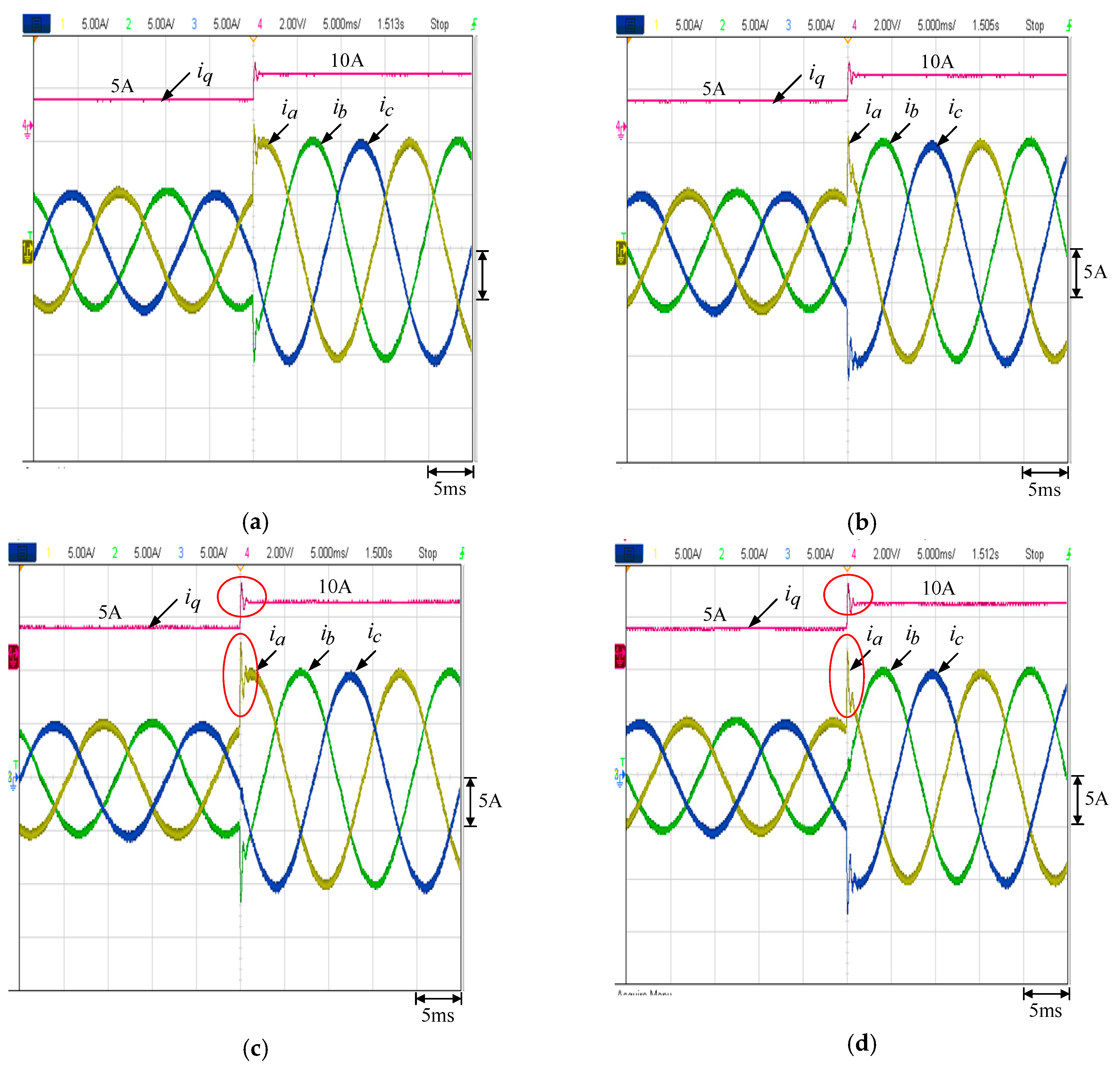
5.1. Constant Current Command

Let the current command be i q = 15 A , i d = 0 A . In this case, the three-phase winding current will be balanced with peak value 15 A. Figure 4a–c show the winding current waveforms measured at different generator speeds. Table 4 summarizes the error and total harmonic distortion (THD) of the measured waveforms. It can be found that the current command tracking error is less than 2.5% in all conditions. The winding current can exactly track the current command. Moreover, the THD is less than 2%, and this means winding currents are nearly sinusoidal.
To improve the scientific merit of this paper, the simulation is performed by PSIM Ver. 10. The same conditions with Figure 4a–c are simulated and shown in Figure 5a–c, respectively. From the simulation results, it can be found that the three-phase winding currents are balanced with peak value 15 A. Moreover, the THD is less than 2%; this means winding currents are nearly sinusoidal.

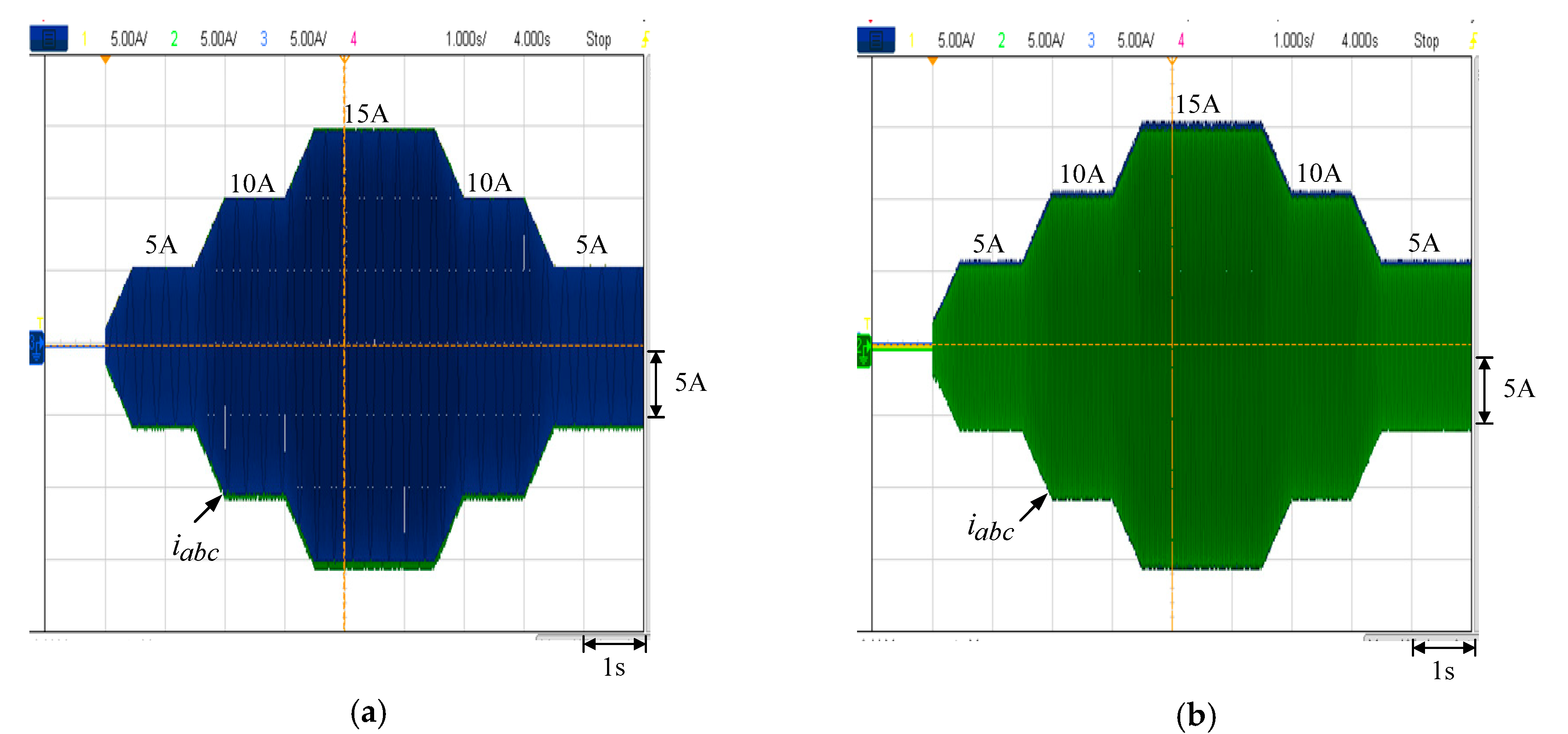
5.2. Variable Current Command

First, the current command i q is stepped from 5 A to 10 A ( i d = 0 ) at 900 rpm. Figure 6a is the step occurring at 60° and Figure 6b is the step occurring at 120°. The results using the IT1 T-S fuzzy system are compared in Figure 6c,d, respectively. The overshoot and settling time of the IT1 and IT2 T-S fuzzy systems are summarized in Table 5. It can be found that the winding currents can achieve the step current command faster by using the proposed IT2 T-S fuzzy control. The overshoot of the IT2 T-S fuzzy system is also less than the IT1 T-S fuzzy system, which makes the developed system more reliable and flexible.
Second, the speed is 1200 rpm and the current command is going from zero to a constant value. Figure 7a,b show the winding current waveforms of the current command that goes from zero to a constant value. The current tracking capability is verified.
Finally, the speed is 900 rpm and 1500 rpm, respectively, and the current command is varying as 0 A→5 A→10 A→15 A→10 A→5 A. Figure 8a,b show the winding current waveforms, respectively. It is obvious that the winding current can track the variable current command very well. The output power of the PMSG can be adjusted by changing the current command in this situation.

5.3. Calculation Time

The calculation time of the IT2 T-S fuzzy and the IT1 T-S fuzzy systems is compared in Figure 9a,b. The calculation time of the IT2 T-S fuzzy is 32.6 μs and the calculation time of the IT1 T-S fuzzy is 30 μs. The IT2 T-S fuzzy system requires 2.6 μs more than the IT1 T-S fuzzy system to process the control algorithm. The switching period of the developed system is 50 μs. Therefore, the proposed algorithm is acceptable in implementation.

6. Conclusions

The current control of the PMSG was designed and implemented based on the IT2 T-S fuzzy systems. First, the system configuration and the dynamic model were introduced. Next, the current controller was designed based on the IT2 T-S fuzzy models. The IT2 T-S fuzzy control system was implemented to consider the uncertainty of nonlinear systems. The stability analysis and detailed design process were also demonstrated. The controller gain could be found by using the LMI conditions. Furthermore, the experimental equipment of the PMSG was illustrated. Experimental results, including constant current command, variable current command and calculation time, were demonstrated to verify the performance of the proposed current control. Simulation results were also performed in constant current command to improve the scientific merit of this paper. The IT2 T-S fuzzy system is more complex than the IT1 T-S fuzzy system. However, its calculation time is acceptable. Furthermore, its overshoot and settling time under the current command variation is better than the IT1 T-S fuzzy system. The output power of a PMSG can be adjusted by changing the peak value of three-phase balanced winding currents. In the future, the sensorless control combined with the IT2 T-S fuzzy systems may be adopted to increase the practicability of the PMSG system.

Author Contributions

The authors contributed equally to this work.

Funding

This research was supported by the Ministry of Science and Technology, Taiwan, under the Grant of MOST 108-2623-E-194-001-D.

Conflicts of Interest

The authors declare no conflict of interest.

References

  1. Krause, P.; Wasynczuk, O.; Sudhoff, S.; Pekarek, S. Analysis of Electric Machinery and Drive Systems, 3rd ed.; IEEE Press: Piscataway, NJ, USA, 2013; pp. 121–141. ISBN 9781118024294. [Google Scholar]
  2. Hong, J.; Lee, H.; Nam, K. Charging method for the secondary battery in dual-inverter drive systems for electric vehicles. IEEE Trans. Power Electron. 2015, 30, 909–921. [Google Scholar] [CrossRef]
  3. Lai, Y.S.; Lee, W.T.; Lin, Y.K.; Tsai, J.F. Integrated inverter/converter circuit and control technique of motor drives with dual-mode control for EV/HEV Applications. IEEE Trans. Power Electron. 2014, 29, 1358–1365. [Google Scholar] [CrossRef]
  4. Lee, K.W.; Park, S.; Jeong, S. A seamless transition control of sensorless PMSM compressor drives for improving efficiency based on a dual-mode operation. IEEE Trans. Power Electron. 2015, 30, 1446–1456. [Google Scholar] [CrossRef]
  5. Yaramasu, V.; Wu, B. Predictive control of a three-level boost converter and an NPC inverter for high-power PMSG-based medium voltage wind energy conversion systems. IEEE Trans. Power Electron. 2014, 29, 5308–5322. [Google Scholar] [CrossRef]
  6. García-Gracia, M.; Cova, M.A.; Villen, M.T.; Uson, A. Novel modular and retractable permanent magnet motor/generator for flywheel applications with reduced iron losses in stand-by mode. IET Renew. Power Gener. 2014, 8, 551–557. [Google Scholar] [CrossRef]
  7. Jung, E.; Yoo, H.; Sul, S.K.; Choi, H.S.; Choi, Y.Y. A nine-phase permanent-magnet motor drive system for an ultrahigh-speed elevator. IEEE Trans. Ind. Appl. 2016, 48, 987–995. [Google Scholar] [CrossRef]
  8. Reddy, P.B.; El-Refaie, A.M.; Huh, K.K. Effect of number of layers on performance of fractional-slot concentrated-windings interior permanent magnet machines. IEEE Trans. Power Electron. 2015, 30, 2205–2218. [Google Scholar] [CrossRef]
  9. Do, T.D.; Kwak, S.; Choi, H.H.; Jung, J.-W. Suboptimal control scheme design for interior permanent-magnet synchronous motors: An SDRE-Based approach. IEEE Trans. Power Electron. 2014, 29, 3020–3031. [Google Scholar] [CrossRef]
  10. Pellegrino, G.; Vagati, A.; Guglielmi, P.; Boazzo, B. Performance comparison between surface-mounted and interior PM motor drives for electric vehicle applications. IEEE Trans. Ind. Electron. 2012, 59, 803–811. [Google Scholar] [CrossRef]
  11. Wang, Z.; Lu, K.; Blaabjerg, F. A simple startup strategy based on current regulation for back-EMF-based sensorless control of PMSM. IEEE Trans. Power Electron. 2012, 27, 3817–3825. [Google Scholar] [CrossRef]
  12. Jahns, T.M.; Soong, W.L. Pulsating torque minimization techniques for permanent magnet AC motor drives—A review. IEEE Trans. Ind. Electron. 1996, 43, 321–330. [Google Scholar] [CrossRef]
  13. Kim, K.C.; Lee, J.; Kim, H.J.; Koo, D.H. Multiobjective optimal design for interior permanent magnet synchronous motor. IEEE Trans. Magn. 2009, 45, 1780–1783. [Google Scholar] [CrossRef]
  14. Islam, R.; Husain, I.; Fardoun, A.; McLaughlin, K. Permanent-magnet synchronous motor magnet designs with skewing for torque tipple and cogging torque reduction. IEEE Trans. Ind. Appl. 2009, 45, 152–160. [Google Scholar] [CrossRef]
  15. Chang, Y.C.; Wang, S.Y.; Dai, W.F.; Chang, H.F. Division-summation current control and one-cycle voltage regulation of the surface-mounted permanent-magnet synchronous generator. IEEE Trans. Power Electron. 2016, 31, 1391–1400. [Google Scholar] [CrossRef]
  16. Hwang, J.-C.; Wei, H.-T. The current harmonics elimination control strategy for six-leg three-phase permanent magnet synchronous motor drives. IEEE Trans. Power Electron. 2014, 29, 3032–3040. [Google Scholar] [CrossRef]
  17. Chou, M.C.; Liaw, C.M. Development of robust current 2-DOF controllers for a permanent magnet synchronous motor drive with reaction wheel load. IEEE Trans. Power Electron. 2009, 24, 1304–1320. [Google Scholar] [CrossRef]
  18. Uddin, M.N.; Radwan, T.S.; George, G.H.; Rahman, M.A. Performance of current controllers for VSI-fed IPMSM drive. IEEE Trans. Ind. Appl. 2000, 36, 1531–1538. [Google Scholar]
  19. Liaw, C.M.; Kang, B.J. A robust hysteresis current-controlled PWM inverter for linear PMSM driven magnetic suspended positioning system. IEEE Trans. Ind. Electron. 2001, 48, 956–967. [Google Scholar] [CrossRef]
  20. Weigold, J.; Braun, M. Predictive current control using identification of current ripple. IEEE Trans. Ind. Electron. 2008, 55, 4346–4353. [Google Scholar] [CrossRef]
  21. Chang, Y.C.; Chen, C.H.; Zhu, Z.C.; Huang, Y.W. Speed control of the surface-mounted permanent-magnet synchronous motor based on Takagi-Sugeno fuzzy models. IEEE Trans. Power Electron. 2016, 31, 6504–6510. [Google Scholar] [CrossRef]
  22. Chang, Y.C.; Chang, H.C.; Huang, C.Y. Design and implementation of the permanent-magnet synchronous generator drive in wind generation systems. Energies 2018, 11, 1634. [Google Scholar] [CrossRef]
  23. Kamiński, M.; Corigliano, A. Numerical solution of the Duffing equation with random coefficients. Meccanica 2015, 50, 1841–1853. [Google Scholar] [CrossRef] [Green Version]
  24. Karnik, N.N.; Mendel, J.M.; Liang, Q. Type-2 fuzzy logic systems. IEEE Trans. Fuzzy Syst. 1999, 7, 643–658. [Google Scholar] [CrossRef]
  25. Mendel, J.M.; John, R.I.; Liu, F. Interval type-2 fuzzy logic systems made simple. IEEE Trans. Fuzzy Syst. 2006, 14, 808–821. [Google Scholar] [CrossRef]
  26. Lai, C.C. Design and Implementation of a Single-Phase Bidirectional Inverter Using Interval Type-2 T-S Fuzzy Control Systems. Master’s Thesis, National Chung Cheng University, Chiayi, Taiwan, 2016. [Google Scholar]
Figure 1. System configuration of the PMSG based on theIT2 T-S fuzzy control systems.
Energies 12 02953 g001
Figure 2. Membership function of the IT2 T-S fuzzy control systems.
Energies 12 02953 g002
Figure 3. Experimental equipment for the PMSG system based on the IT2 T-S fuzzy systems.
Energies 12 02953 g003
Figure 4. Winding current waveforms by letting i q = 15 A and i d = 0 A at different generator speeds: (a) 600 rpm, (b) 900 rpm and (c) 1200 rpm.
Energies 12 02953 g004
Figure 5. Simulation winding current waveforms by letting i q = 15 A and i d = 0 A at different generator speeds: (a) 600 rpm, (b) 900 rpm and (c) 1200 rpm.
Energies 12 02953 g005
Figure 6. Winding current waveforms of the current command stepped from 5 A to 10 A at 900 rpm: (a) step occurs at 60° with IT2 T-S fuzzy, (b) step occurs at 120° with IT2 T-S fuzzy, (c) step occurs at 60° with IT1 T-S fuzzy and (d) step occurs at 120° with IT1 T-S fuzzy.
Energies 12 02953 g006
Figure 7. Winding current waveforms of the current command goes from zero to a constant value at 1200 rpm: (a) 10 A; (b) 15 A.
Energies 12 02953 g007
Figure 8. Winding current waveforms of the current command is varying as 0 A→5 A→10 A→15 A→10 A→5 A: (a) 900 rpm; (b) 1500 rpm.
Energies 12 02953 g008
Figure 9. Calculation time of the IT2 T-S fuzzy and the IT1 T-S fuzzy systems: (a) IT2 T-S fuzzy; (b) IT1 T-S fuzzy.
Energies 12 02953 g009
Table 1. Antecedent variables and boundaries of the PMSG.
Boundariesapbpcpdp
Antecedent
z10 A1.8 A17.1 A18.9 A
z20 rad/sec76 rad/sec716 rad/sec792 rad/sec
Table 2. Parameters of the PMSG.
PolesrsLdLq
80.24 Ω1.896 mH2.131 mH
Rated SpeedRated TorqueRated CurrentRated Power
1800 rpm23 N·m11.8 Arms4.5 kW
Table 3. Specifications of the PMSG Drive.
Rated power5 kWDC-link voltage380 Vdc
Rated voltage220 VrmsDC-link capacitance5600 µF
Rated current13.1 ArmsSwitching frequency20 kHz
Table 4. Error and THD of the measured waveforms.
Generator SpeedMeasured Current (A)Error (%)THD (%)
600 rpm14.8491.011.35
900 rpm15.1791.191.20
1200 rpm15.3682.451.50
Note: error(%) = | measured current current command current command | × 100 % , THD(%) = ( THD a + THD b + THD c 3 ) .
Table 5. Overshoot and settling time of the IT1 and IT2 T-S fuzzy systems.
Step PositionControl SystemOvershootSettling Time
Step occurs at 120°IT1 T-S fuzzy2.375 A1.03 ms
IT2 T-S fuzzy2.25 A0.92 ms
Step occurs at 60°IT1 T-S fuzzy2.125 A1.12 ms
IT2 T-S fuzzy2.03 A1.03 ms
Note: overshoot = ( maximum current desired current ) settling time: the required time when current tracking error is less than 5%.

