Abstract
An improved direct torque control with space-vector modulation (DTC-SVM) scheme is presented in this paper. In the conventional DTC-SVM scheme, torque control performance is affected by the load conditions, due to the inappropriate linearization of the relationship between the flux angle and electromagnetic torque. Different from the conventional method, a torque controller with load angle estimation (TC-LAE) is proposed and the change rate of torque is regulated according to the variation of the load conditions, which could ensure the rapidity and consistency of torque performance at different load conditions. Meanwhile, an online permanent magnet synchronous motor and maximum torque per ampere (PMSM-MTPA) operation strategy based on the fitting solving method is proposed instead of the traditional two-dimensional look-up table, and the reference value of flux amplitude is calculated online to meet the MTPA requirement with the proposed method. The improved strategy is applied on a 6 kW PMSM, and the simulation and experimental results verified the effectiveness and the feasibility of the proposed strategy.
1. Introduction
A lot of work has been done to improve dynamic torque performance and to optimize the output efficiency of the torque of permanent magnet synchronous motors (PMSMs) in recent years [1,2,3,4,5,6,7,8]. Additionally, various optimal torque control strategies have been proposed, such as direct torque control (DTC) [4,5], predictive torque control [6,7] and nonlinear control strategies [8], etc. The DTC strategy combined with space vector pulse width modulation (PWM) [9], which used continuous rotated voltage vector to regulate the flux of the motor. The torque control performance was improved compared with conventional DTC [10,11,12,13].
The DTC-SVM scheme usually consists of two parts [14]: one is the selection of the flux reference based on the two-dimensional look-up table offline. In this part, the reference value of the current is achieved using the torque–current table based on the maximum torque per ampere (MTPA) criterion, and then, the reference value of flux is calculated according to the relationship between flux and current of the motor. Hence, the MTPA operation of the DTC-SVM scheme could be achieved [15]. The other is the calculation of the reference flux angle based on the proportional integral (PI) controller. The relationship between the electromagnetic torque and the flux angle is linearized approximately, which resulted in excellent torque performance which could be maintained at different load conditions.
The research of DTC-SVM scheme always focuses on two aspects: one is to reduce the impact on the MTPA operation brought about by the change of parameters of the motor. The other is to improve the control/precision of the torque against variations in the load conditions.
The validity of the data in the torque–current two-dimensional table depends on the accuracy of the motor’s parameters in the selection mechanism of the reference flux amplitude. Slow variation of the parameters is inevitable because of copper loss and magnetic saturation. Hence, the operation’s conditions might deviate from the MTPA [16]. Therefore, the online MTPA control is an ideal solution to these problems. At present, the online solution of MTPA could be classified into the direct solving method [17] and engineering optimization method [18,19]. The MTPA criterion is a fourth-order equation about the stator current. The direct solving method is to solve this fourth-order equation online using the Ferrari method. Then, the reference value of the current could be obtained. The engineering optimization method is to change the fourth-order equation to an online optimization problem. The direct solving relationship between the torque and MTPA criterion is established. The voltage limitations of the inverter, the extreme current of the motor and the operational conditions are used as the boundary criterions. The stator current, which meets the MTPA criterion, is the optimization object. Then, the solving of the current reference value is realized. After that, the reference value of the stator flux amplitude for the DTC-SVM scheme could be obtained with this reference value of the current [20]. It is worth illustrating that the impacts of parameter variation on the online MTPA operation can be eliminated using certain parameter identification or self-adaptive methods.
The linearization of the relationship between the flux angle and electromagnetic torque is used as the control object for the torque control of the conventional DTC-SVM scheme, thus, the torque loop can be regarded as a second-order system with a PI controller. However, the dampening of this torque loop will be affected by the load conditions, which could lead to different torque adjustable performances of the conventional DTC-SVM scheme. There are three kinds of control strategies to improve the performance of torque control caused by inappropriate linearization:
- Variable parameter PI control. A third-order characteristic curve of the relationship between the parameters of the PI controller and the load torque is established by the interpolation fitting method. The parameters of the PI controller will be adjusted according to the curve mentioned before to eliminate the impact of load torque on the performance of PI control [21].
- Nonlinear control. Back-stepping control [22], variable structure control [23], sliding mode control [24,25] and other nonlinear controllers are utilized to realize torque control. The nonlinear controller has the advantages of a rapid dynamic response and good adaptability against external disturbances and nonlinearity of the parameters. The dynamic performance of the motor is rapid and consistent under different load conditions.
- Deadbeat torque control [26,27,28] and predictive torque control [29,30,31]. The deviation of the torque is used as the input, and the required stator voltage for torque control can be obtained by the predictive mechanism. In these kinds of strategies, the stator voltage is adjusted online to eliminate the impact of load on the performance of torque by the predictive/deadbeat controller according to the mathematical model and load condition of the motor.
To improve the performance of the conventional DTC-SVM, a novel online MTPA method based on Lagrange interpolation and an improved torque controller with load angle estimation (TC-LAE) are proposed in this paper. Different from the existing MTPA scheme, the proposed MTPA scheme takes the stator flux linkage as a variable instead of the stator current. Furthermore, the direct selection of the reference flux amplitude satisfied with the MTPA criterion could be realized on-line by Lagrange interpolation. Besides, a P-type torque controller with load angle estimation is adopted instead of the inappropriate linearization PI controller, so that the parameters of torque controller could be adjusted online according to the actual load angle to improve the control performance of torque under different load conditions.
2. Examination of Conventional DTC-SVM Scheme
The structure diagram of the conventional DTC-SVM scheme is shown in Figure 1.
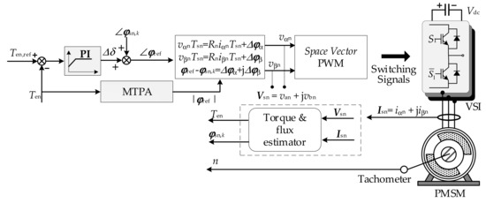
Figure 1.
The conventional direct torque control with space-vector modulation (DTC-SVM) scheme.
2.1. Selection of Reference Flux Amplitude Based on the MTPA Criterion
When operating below the rated speed of a PMSM, the MTPA operation should be satisfied for high-efficiency operation, which means the relationship between the electromagnetic torque and the stator current might meet the requirements of the following equations [15].
During mathematical derivation of this paper, the per-unit value is employed for generality. The base value is selected as follows: ib = iN; Lb = φb/ib; φb = φr; Teb = 1.5pφbib; Tsb = 1/ωN.
The reference value of idn and iqn that meet the requirement of the MTPA criterion are obtained using look-up table, and the equation of the flux linkage after normalization can be obtained by:
where, φ’dn = Ldnidn. Furthermore, the reference value of stator flux amplitude is:
It can seen from Equations (1)–(3) that the MTPA operation of the PMSM depends on the accuracy of the motor’s parameters. Hence, the online MTPA operation method could be used to reduce the impact of the parameters on the operation of the MTPA. The essence is changing the offline look-up table which meets the requirement of Equation (1) to solve the fourth-order equation online, which takes id as the independent variable and Ten as the parameter. Finally, the reference amplitude could be obtained using the square root operation, as shown in Equation (3).
2.2. Torque Control Based on the PI Controller
The electromagnetic torque can be written as the expression of the flux amplitude and load angle, which is [14]:
where, ρ = Lqn/Ldn, ρ > 1. δ represents the load angle, which is the angle between the stator voltage vector and the flux vector. The incremental quantity of the load angle ∆δ is related to the phase angle of the motor’s stator flux vector.
The approximate linearization processing of Equation (4) is taken when the load angle is δ0
where,
The PI controller is used to realize torque control for the conventional DTC-SVM scheme, according to Equation (6). The structure block diagram of the torque loop is shown in Figure 2. The close-loop transfer function of the torque control link could be obtained from this figure, and the damping ζ and natural characteristic frequency ωn can be derived as:
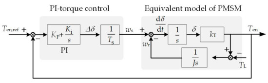
Figure 2.
The control block of the torque loop.
In the block diagram, as shown in Figure 2, the tuning processing of the parameters of the PI controller is as follows: firstly, the expectation value of ζ is 0.707 in engineering practice. Secondly, considering the regulation performance and the disturbance immunity of the control system, Ti can usually be chosen as 15 Ts to 25 Ts in the digital control system, where Ti = Kp/Ki [32]. At last, the change rate of torque kT corresponding certain load conditions is selected to calculate the parameters of the PI controller generally.
However, kT varies for different parameters, stator flux amplitudes and load angles of the motor, and because of the nonlinear characteristic of Equation (7), it is hard to select a particular kT to tune the PI parameters. For example, the change curve of kT is calculated according to (7), where the stator flux amplitude changes from 0.6 to 1.0 (per-unit value) and the load angle changes from 0.0 to 1.5 (per-unit value), as shown in Figure 3.
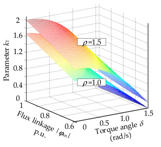
Figure 3.
The relationship of the torque change rate kT with the flux amplitude and load angle.
As shown in Figure 3, kT is mainly affected by the load angle of the motor. The heavier the load is, the smaller the value of kT is, inversely. So if kT under the rated load condition is used to calculate the PI parameters, the kT would be increased under light load conditions. Thus, it can be known from equation (9), ζ will be larger than 0.707 for light load operations, so the adjustment time of the transiente torque will be longer. Conversely, if kT under the no-load condition is used, kT will be decreased when operating under rated load conditions. Then, ζ is smaller than 0.707, which is possible to cause an oscillation process of the torque regulation.
3. An Improved DTC-SVM Scheme
The block diagram of the proposed improved DTC-SVM scheme is presented in Figure 4. For the reference calculation of the flux amplitude, a novel MTPA criterion expressed by the stator flux linkage is constructed, and the reference value of flux amplitude can be obtained with Lagrange interpolation online directly. For the reference calculation of flux phase angle, this section puts forward a novel P-type torque controller with load angle estimation (TC-LTE), which could regulate the flux phase angle as load angle variation. Moreover, by adding the relevant correction, compensation and limitation blocks for the incremental quantity of the load angle ∆δ, the impact of the voltage limitation circle, rotation of the permanent magnet and load angle stability on the torque control performance could be depressed.
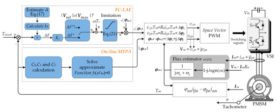
Figure 4.
The schematic diagram of the proposed DTC-SVM scheme.
3.1. Novel Online MPTA Scheme
By substituting (2) into (1), the following equation can be derived:
where, a = (1 − ρ)3ρ2; b = 3ρ2(1 − ρ)2; c = 3ρ2(1 − ρ); d = ρ2; e = −(1 − ρ).
Equation (10) is a novel MTPA criterion expressed by flux linkage; it can determine the reference flux amplitude that satisfied MTPA criterion under different load conditions directly.
In order to solve (10), Lagrange interpolation is adopted to fit the left polynomial of (10). Then, the feasible solution of (10) is equivalent to the zero point of the fitting polynomial. At last, the reference value of the flux amplitude can be determined with simple calculation. Assuming:
According to the theory of Lagrange interpolation [33], there are two necessary steps to fit the above polynomial. The first step is to confirm the solution region of (10). The second step is to select the samples and calculate the remainder of the interpolation.
Calculating the derivative of φ′dn in (11), and making this derivation equal to zero, that is:
The above equation has a single real root and a double real root . Taking the second order derivative at these two points, we can get and . Obviously, and are the maximum points of f1. Besides, considering the intercept of the φ′dn − f1 plot, f1(0) = eTen2Lqn2 > 0, it can be concluded that (10) has one positive solution and one negative solution. Furthermore, as shown in (1), idn < 0. Hence, the negative solution could be the unique feasible solution of (10). The schematic diagram of the interpolation trajectory and its remainder are drawn in Figure 5.
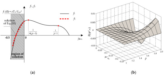
Figure 5.
The schematic diagram of the interpolation trajectory and remainder. (a) Interpolation; (b) remainder of interpolation.
To avoid the irreversible demagnetization of the permanent magnet, always keep φ′dn > −0.5 [34]. Therefore, the solution region of (10) can be determined as (−0.5, 0).
In general, the value of φ′dn is always small under the MTPA operation, then the interplotion samples could be selected in [−0.25, 0]. This section adopted Lagrange parabolic interpolation to fit the curve of f1, and the interplotion samples are chosen as (0, C0), (−0.15, C1) and (−0.25, C2), where , and , respectively. Based on the interpolation formula [33], The final interpolation polynomial can be expressed as follows:
and the interpolation remainder for (13) is:
For φ′dn ∈ [−0.25, 0] and ρ ∈ [1.0, 2.0], the numerical analysis results of Rn(φ′dn) is shown in Figure 5b. It can be seen from this figure that −0.01 < Rn(φ′dn) < 0.01, thus the solution of f2(φ′dn) = 0 could be regarded as the solution of (10), approximately. This means that we can determine the reference flux amplitude with the solution of f2(φ′dn) = 0 online, and the complex process for solving (10) directly can be avoided. Particularly, the following extra conditions must be satisfied during the determination of the reference flux amplitude.
- To ensure stable operation of the PMSM, the reference value of the flux amplitude [20],
- 2.
- If the PMSM works under no-load conditions, the electromagnetic torque and stator current are almost zero. According to (3),
3.2. Torque Controller with Load Angle Estimation (TC-LAE)
The control block of the proposed TC-LAE is shown Figure 4. The estimation equation of the load angle can be expressed with stator current and flux, which is:
by substituting the estimated load angle into (7), we can predict the value of kT in real-time. Furthermore, the incremental quantity of the load angle at the next control instant, which is denoted as ∆δ, can be obtained by taking the difference operation on both sides of (4), that is:
In addition, a P-type controller is employed in the TC-LAE for ∆δ trimming, to depress the impact of several disturbance factors, such as sampling error and parameter mismatches, on torque performance. The control parameter of this P-type controller is Kc, and Kc > 0.
The conventional DTC-SVM takes a constant kT for the parameter tuning of the PI controller. Differening from the conventional method, the proposed TC-LAE adjusts ∆δ with the appropriate kT, which is calculated based on the actual load angle. With the aid of TC-LAE, the improved DTC-SVM can achieve a fast and consistent torque response under different load conditions.
3.3. Correction, Compensation and Limitations of ∆δ
3.3.1. Correction
In DTC-SVM strategies, during large torque demands, the torque controller will give an output that demands the selection of voltage vectors to increase the torque. However, once the reference voltage vector tip point lies outside the hexagon, the space-vector PWM yields a negative time length, resulting in an inevitable volt-seconds error [35,36]. A voltage vector on the hexagon boundary (the modified reference voltage vector) must be selected and at least one back step has to be taken to recalculate the vector time lengths that generate the modified reference voltage vector. Shown in Figure 6, the two popular modified reference vector choices are the minimum magnitude error PWM (MMEPWM) method (also called the one-step-optimal method), and the minimum phase error PWM (MPEPWM) method. However, the MMEPWM and MPEPWM could not ensure the stable output of the load angle and flux amplitude simultaneously at the transient instant [37]. Hence, a special voltage vector correction algorithm is proposed in this section, which is shown in Figure 6.
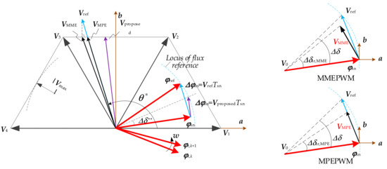
Figure 6.
The correction algorithm of the incremental value of the load angle.
Assuming the reference torque is increased at the instant kTs, and φsn,k donotes the current stator flux vector; φref denotes the reference stator flux vector; Vref denotes the reference vetor of the stator voltage obtained by (17), which hopes to make the stator flux vector (φsn,k+1) equal to φref at the instant (k + 1)Ts. However, it can be seen from Figure 6 that the actual voltage vector is Vact due to the existance of the voltage limitation circle. Consequently, φsn,k+1 could not follow φref under the effects of Vact, it will lead to an ampltide error for flux control. To make sure |φsn,k+1| = |φref |, and fullly ulitize the voltage capablity of the VSI at the same time, we should revise ∆δ when the amplitude of Vref is beyond the voltage limitation circle. On the basis of the vector raltionship in Figure 6, and with the help of cosine theorem, the revised ∆δ** can be derived as:
where, Tsn denotes the per-unit value of the control period, and the base value of time is selected as 1/ωN, ωN is the rated electrical angular frequency of the PMSM; Vref denotes the voltage vector with the ∆δ revising algorithm, its amplitude equals the maximum value of the output voltage of the VSI.
3.3.2. Compensation
The rotor permanent magnet of the PMSM keeps rotating during normal operation. Assuming the rotor rotates counterclockwise, and ω denotes the rotor electrical angular frequency, it can be seen from Figure 6 that the value of ∆δ obtained by controller is ωTs less than the actual required value because of the rotation of the permanent magnet. This angular deviation will result in offsets for torque control during high speed operations, hence it is necessary to compensate the angular deviation, that is:
3.3.3. Limitation
Load angle stability must be ensured when the PMSM is operating under heavy load conditions, hence, the limitation block should be utilized for ∆δ adjustment. Taking the derivative of δ in (7), and making this derivation equal to zero, the maximum load angle δm can be obtained:
Therefore, the maximum allowable vaule of ∆δ (denoted as ∆δm) can be obtained:
4. Simulation Results
In order to study the control performance of the proposed TC-LAE, numerical simulations have been carried out using Matlab/Simulink. The parameters of the control system are presented in Table 1. It should be illustrated that the speed loop consisting of a PI controller is added out of the torque loop. The maximum value of the output torque, which is restricted by the PI controller of the speed loop, is 1.2TN, which is 230 Nm.

Table 1.
Parameters of the control system.
4.1. The Correction and Compensation for ∆δ
The simulation waveforms with/without the correction algorithm for ∆δ are shown in Figure 7. The motor operates at 100 r/min with no load. When t = 1.5 s, the reference value of speed nref is set to 200 r/min, the speed PI controller reaches the positive limitation. Without the correction algorithm, ∆δ increased rapidly, resulting from the sudden increase of Tref. The amplitude of the stator voltage vector is increased correspondingly according to the analysis in Section 3.3. As can be seen from Figure 7, taking the voltage amplitude limitation of the SVM into consideration, when the reference voltage (vα, vβ)is beyond the range of the voltage limitation circle, the amplitude of the stator flux linkage |φs| slides for a short time and a dynamic deviation will appear between the reference value and the actual value of the stator flux linkage. So, the stator current will increase rapidly(imax = 23 A). With the correction algorithm, the tracking ability of the flux control is improved, and the dynamic current is reduced effectively when the reference torque is changed suddenly(ia,max = 21 A).
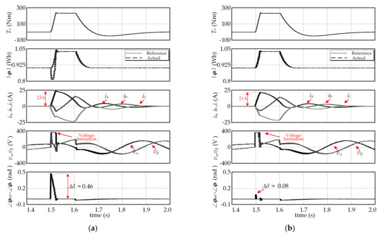
Figure 7.
The simulation waveforms for the proposed DTC-SVM Scheme. (a) Waveforms with ∆δ correction; (b) waveforms with ∆δ correction.
4.2. Selection of the Torque Controller Parameter, Kc
The impact of the selection of Kc on the static and dynamic performance is analyzed in this section. The standard deviation is used to evaluate the extent of the torque ripple in the anaylsis process. That is:
where, , n is the number of samples and n = 1000.
In the simulation, the motor is operated stably at 100 r/min with 50 Nm. When t = 0.1 s, nref is set to 200 r/min. When Kc is between 0.2 and 2.5, the variation rules of the static torque ripple σT and the regulating time of electromagnetic torque td are shown in Figure 8:
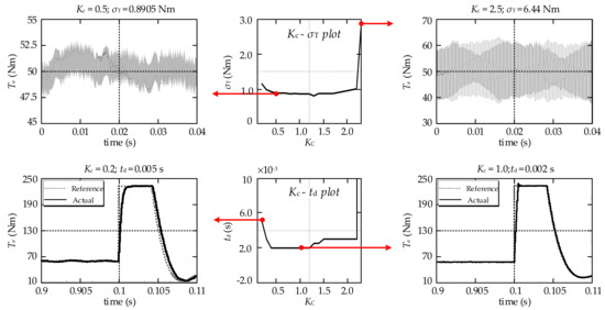
Figure 8.
Steady and transient torque performance of the proposed DTC-SVM scheme under different values of Kc.
- When the value of Kc is less than 2.0, the torque ripple of the motor is small. When the value of Kc is greater than 2.0, the static oscillation of the electromagnetic torque appears.
- When the value of Kc is between 0.5 and 2.0, the dynamic performance of the electromagnetic torque is basically consistent. When the value of Kc is less than 0.5, the regulating time of the torque becomes longer. So, the dynamic performance of the system is degraded.
4.3. Dynamic Characteristic of the Motor Control System
The dynamic simulation waveforms of the improved DTC-SVM scheme and the conventional DTC-SVM scheme are shown in Figure 9. In the simulation, for the conventional DTC-SVM scheme, the parameters of the speed PI controller are consistent with Table 1, the torque PI controller are Kp = 6.25 × 10⁻⁴ and Ti = 20 Ts. The motor is operated at a steady-state of 100 r/min with 50 Nm. When t = 0.1 s, nref is set to −100 r/min and the motor is rotating in reverse. When t = 0.2 s, nref is set to 100 r/min again and the motor rotates normally. When t = 0.3 s, the load is suddenly increased to 150 Nm.
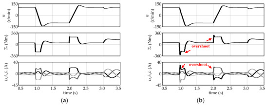
Figure 9.
Speed dynamic simulation waveforms. (a) The improved DTC-SVM scheme; (b) the conventional DTC-SVM scheme.
As can be seen from Figure 9, the improved DTC-SVM scheme inherits the advantages of the conventional scheme, which has a rapid torque response and excellent stator currents. Meanwhile, because the torque loop of the conventional DTC-SVM is a second-order system, overshoot during torque regulation will inevitably occur. However, the improved DTC-SVM regulates the electromagnetic torque using kT varied with the current load condition, so overshoots of the electromagnetic torque has been restrained to some extent.
5. Experimental Results
To verify the feasibility and effectiveness of the improved DTC-SVM scheme, experiments have been carried out on a 6 kW PMSM. The parameters of the experimental setup is consistant with the simulation, which is shown in Table 1. In the experimental setup, which is shown in Figure 10, a TMS320F28335 digital signal processor (DSP) is employed for the control strategy; the stator currents are measured by a LA-50P Hall sensor produced by LEM® (Geneva, Switzerland), and the DC-side voltage is measured by the VSM025A Hall sensor, and the sampling tasks of the stator currents and DC-side voltage are accomplished by the DSP; the angular velocity is obtained from the incremental mode optical shaft angle encoder; the electromagnetic torque is estimated with the mathematical model of the PMSM. Besides, the sampling and control period of the DSP is 200 μs.
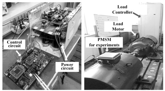
Figure 10.
Photograph of the experimental setup.
5.1. MTPA Operation
In the simulations and experiments, the motor operated at 100 r/min. At first, the motor is operated at 20 Nm, and the load is added at 20 Nm per time, until the load reaches 200 Nm. The actual electromagnetic torque, amplitude of stator flux linkage, average value of d-/q-axis currents and RMS value of the phase current under each load condition are measured, and the experimental data are plotted in Figure 11.
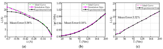
Figure 11.
The performance of proposed on-line maximum torque per ampere (MTPA) method. (a) id – iq plot; (b) Te − |s| plot; (c) Te – IA plot.
It can be seen from Figure 11 that the MTPA trajectory obtained by simulation and experiments with the proposed online MTPA method almost coincide with the theoretical MTPA trajectory based on Equation (1).
5.2. Torque Control Performance
Figure 12 and Figure 13 give the experimental waveforms with the conventional DTC-SVM scheme using two different parameters of torque PI controllers, which are calculated with kT under no-load and rated load conditions, respectively. Figure 14 gives the experimental waveforms with the improved DTC-SVM scheme. In the experiments, firstly, the motor is operated at 100 r/min with no load and 50 Nm load, respetively. Next, the reference speed is increased to 200 r/min. Besides, to assure the incremental quantities of electromagnetic torque are consistent for different load conditions, the limitation of the speed PI controller is set to 100 Nm when the motor is operating under the no load condition, and 150 Nm for the 50 Nm load, correspondingly.
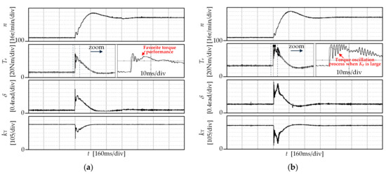
Figure 12.
Experimental waveforms of the conventional DTC-SVM scheme during transient operation at Kp = 6.25 × 10⁻⁴; Ti = 20 Ts. (a) No load; (b) 50 Nm load.
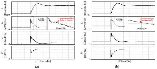
Figure 13.
Experimental waveforms of the conventional DTC-SVM scheme during transient operation at Kp = 2.0 × 10⁻⁴; Ti = 20 Ts. (a) No load; (b) 50 Nm load.
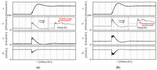
Figure 14.
Experimental waveforms of the improved and conventional DTC-SVM scheme during transient operation. (a) No load; (b) 50 Nm load.
In Figure 12, the parameters of the torque controller of the conventional DTC-SVM scheme are calculated by the constant kT corresponding to the no load condition. Then, it can be obtained that Kp = 6.25 × 10⁻⁴ and Ti = 20 Ts. It can be seen from Figure 12 that the motor has favorable torque performance when operating under the no load condition. However, the dampening of the torque loop will be decreased on account of the decreased kT when the motor operates with a 50 Nm load, and this will cause na oscillation process during the transiente torque.
In Figure 13, the parameters of the torque controller of the conventional DTC-SVM scheme are calculated by the constant kT corresponding to the rated load condition. Then, it can be obtained Kp = 2.0 × 10⁻⁴ and Ti = 20 Ts. It can be seen from Figure 13 that the torque response is favorable when the motor is operated with a 50 Nm load. However, the damping of the torque loop will be increased because of the increment of kT when the motor is operating under the no load condition, resulting in a longer regualtion time of the eletromagnetic torque than the no load condition.
It can be seen from Figure 14 that the motor has a rapid and consistent torque response when operated under different load conditions for the proposed DTC-SVM scheme.
5.3. Characteristics of the Torque Controller
Figure 15 gives experimental waveforms with/without the compensation algorithm mentioned in Section 3.3. In the experiment, the motor is operated at 200 r/min with no load steadily. As shown in Figure 15, with the compensation algorithm, the electromagnetic torque could track its reference value without static error. While without the compensation algorithm, there are deviations between the electromagnetic torque and reference torque.
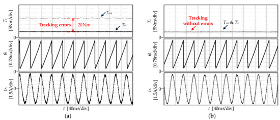
Figure 15.
Experimental waveforms with/without compensation for the proposed DTC-SVM. (a) Without compensation; (b) with compensation.
Figure 16 gives the experimental waveforms of torque response for the value of Kc equal to 0.2, 1.0 and 2.0, respectively. In the experiments, firstly, the motor is operated at 100 r/min with no load. Next, the load is increased to 50 Nm. As can be seen from Figure 16, with the increase of Kc, the ripple amplitude of the static torque is also increased, but the motor has a faster torque dynamic response; with the decrease of Kc, although the ripple amplitude of the static torque is decreased, the dynamic performance of the motor deteriorated. Obviously, the above experimental results are consistent with the simulation.
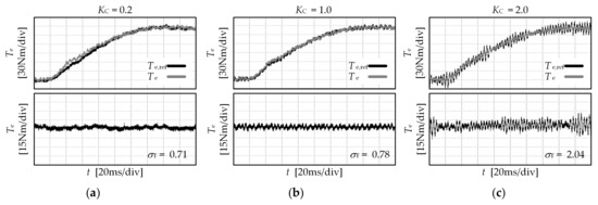
Figure 16.
Transient and steady torque performance of the proposed DTC-SVM scheme with different values of Kc. (a) Kc = 0.2; (b) Kc = 1.0; (c) Kc = 2.0.
6. Conclusions
The constant torque change rate is used to regulate the electromagnetic torque in the conventional DTC-SVM, and the variation of the torque change rate has not been taken into consideration. Therefore, this kind of control mode will lead to a phenomenon where dampening of the torque control changes with the variation of the output torques. So, the dynamic performances of the electromagnetic torque are different under different output torque conditions. In order to solve this problem, this paper puts forward an improved DTC-SVM scheme. Compared with the conventional scheme, the proposed scheme adopts a torque controller with torque angle estimation (TC-LAE). With this torque controller, the torque change rate is adjusted in real-time according to the variation of the output electromagnetic torques. The dynamic performance of the torque control is improved. Meanwhile, for the determination of the reference flux amplitude, the MTPA criterion expressed by the flux linkage is established and the Lagrange interpolation fitting method is used to realize the on-line MTPA operation of the PMSM. With the proposed online MTPA method, we can determine the reference flux amplitude directly that could ensure the PMSM-MTPA operation, instead of utilizing the traditional two-dimensional look-up table. The simulation and experimental results of the improved and conventional scheme were researched using a 6 kW PMSM. The conclusions are as follows:
- The improved scheme inherits the advantages of the conventional DTC-SVM scheme. The torque control ability under different load conditions has been improved; the impact of load variation on torque performance has been eliminated.
- The reference value of the stator voltage given by the torque controller maybe exceed the range of the voltage limitation circle when the electromagnetic torque is changed suddenly. Then, the tracking deviation of the flux occurs and causes an impulse of the current. With the corresponding correction algorithm, the impact of the voltage limitation circle on the performance of torque control is eliminated.
- To eliminate the deviation of torque control resulting from the rotation of the permanent magnet; a compensation term was added to the reference value of the flux phase angle in the improved scheme, and a no-error control of the electromagnetic torque was realized.
- The selection of the torque control parameter Kc will impact the torque control performance in the improved scheme. The selection of Kc is analyzed by the simulation and experiment. The analysis results show that the torque ripple becomes greater when the Kc is large; the dynamic performance of the torque is degraded when the Kc is small.
Author Contributions
Conceptualization, Z.Z. and Z.W.; methodology, Z.Z.; software, Z.Z.; validation, X.G. and G.Z.; formal analysis, Z.Z. and Q.G.; writing—original draft preparation, Z.Z.; writing—review and editing, Z.Z. and G.Z., and; funding acquisition, Z.Z.
Funding
This research was funded by “The Science & Technology Development Fund of Tianjin Education Commission for Higher Education, grant number 2018KJ207”.
Conflicts of Interest
The authors declare no conflict of interest.
Nomenclature
| v, i, φs, φr | Stator voltage, current and flux, permanent magnet flux |
| φs, Vs, Is | Stator flux, voltage and current vector |
| ωm, ω | Mechanical and electrical angular velocity |
| Te, δ, ρ | Electromagnetic torque, load angle and salient rate of the motor |
| p, L, R | Number of pole pairs, stator inductance, stator resistance |
| kT, Kc | Change rate of torque, control parameter of load angle controller |
| Kp, Ki, Ts | Proportionality coefficient, integral coefficient and control period |
| ABC, αβ, dq | Three-phase, two-phase stationary frame and rotating reference frame |
| |·|, ∠, ∆ | Amplitude and phase angle of vector, Incremental quantity of variables |
| b, n, N (subscript) | Base value, per-unit value and rated value |
| k, (subscript) | Variables at the instant kTs |
| ref, 0 (subscript) | Reference value and balance point value |
References
- Wang, D.; Yuan, T.; Wang, X.; Wang, X.; Ni, Y. Performance improvement of servo control system driven by dovel PMSM-DTC based on fixed sector division criterion. Energies 2019, 12, 2154. [Google Scholar] [CrossRef]
- Wang, F.; Zhang, Z.; Mei, X.; Rodríguez, J.; Kennel, R. Advanced control strategies of induction machine: Field oriented control direct torque control and model predictive control. Energies 2018, 11, 120. [Google Scholar] [CrossRef]
- Pavel, K.; Jiri, L. Induction motor drive direct torque control and predictive torque control comparison based on switching pattern analysis. Energies 2018, 11, 1793. [Google Scholar]
- Wang, D.; Yuan, T.; Wang, X.; Wang, X.; Li, W. A Composite vectors modulation strategy for PMSM DTC systems. Energies 2018, 11, 2729. [Google Scholar] [CrossRef]
- Milutin, P.; Nebojša, M.; Vojkan, K.; Bojan, B. An improved scheme for voltage sag override in direct torque controlled induction motor drives. Energies 2017, 10, 663. [Google Scholar] [CrossRef]
- Li, H.; Lin, J.; Lu, Z. Three vectors model predictive torque control without weighting factor based on electromagnetic torque feedback compensation. Energies 2019, 12, 1393. [Google Scholar] [CrossRef]
- Xu, Y.; Shi, T.; Yan, Y.; Gu, X. Dual-vector predictive torque control of permanent magnet synchronous motors based on a candidate vector table. Energies 2019, 12, 163. [Google Scholar] [CrossRef]
- Song, Q.; Li, Y.; Jia, C. A novel direct torque control method based on asymmetric boundary layer sliding mode control for PMSM. Energies 2018, 11, 657. [Google Scholar] [CrossRef]
- Hoang, K.D.; Ren, Y.; Zhu, Z.Q.; Foster, M. Modified switching-table strategy for reduction of current harmonics in direct torque controlled dual-three phase permanent magnet synchronous machine drives. IET Electr. Power Appl. 2015, 9, 10–19. [Google Scholar] [CrossRef]
- Xia, C.; Zhao, J.; Yan, Y.; Shi, T. A novel direct torque control of matrix converter-fed PMSM drives using duty cycle control for torque ripple reduction. IEEE Trans. Ind. Electron. 2014, 61, 2700–2713. [Google Scholar] [CrossRef]
- Yan, Y.; Zhao, J.; Xia, C.; Shi, T. Direct torque control of matrix converter-fed permanent magnet synchronous motor drives based on master and slave vectors. IEEE Trans. Power Electron. 2015, 8, 288–296. [Google Scholar] [CrossRef]
- Zhu, Z.Q.; Ren, Y.; Liu, J. Improved torque regulator to reduce steady-state error of torque response for direct torque control of permanent magnet synchronous machine drives. IET Trans. Electr. Power Appl. 2014, 8, 108–116. [Google Scholar] [CrossRef]
- Buja, G.S.; Kazmierkowski, M.P. Direct torque control of PWM inverter-fed AC motors-a survey. IEEE Trans. Ind. Electron. 2004, 51, 744–757. [Google Scholar] [CrossRef]
- Tang, L.; Zhong, L.; Rahman, M.F.; Hu, Y. Novel direct torque controlled interior permanent magnet synchronous machine drive with low ripple in flux and torque and fixed switching frequency. IEEE Trans. Power Electron. 2004, 19, 346–354. [Google Scholar] [CrossRef]
- Inoue, Y.; Morimoto, S.; Sanada, M. Control method suitable for direct-torque-control-based motor drive system satisfying voltage and current limitations. IEEE Trans. Ind. Appl. 2012, 48, 970–976. [Google Scholar] [CrossRef]
- Krishnan, B. Permanent Magnet Synchronous and Brushless DC Motor Drives; CRC Press: Boca Raton, FL, USA, 2009; Chapter 7. [Google Scholar]
- Jung, S.Y.; Hong, J.; Nam, K. Current minimizing torque control of the IPMSM using Ferrari’s method. IEEE Trans. Power Electron. 2014, 28, 5603–5617. [Google Scholar] [CrossRef]
- Preindl, M.; Bolognani, S. Optimal state reference computation with constrained MTPA criterion for PM motor drives. IEEE Trans. Power Electron. 2015, 30, 4524–4535. [Google Scholar] [CrossRef]
- Lemmens, J.; Vanassche, P.; Driesen, J. PMSM drive current and voltage limiting as a constraint optimal control problem. IEEE J. Emerg. Sel. Top. Power Electron. 2015, 3, 326–338. [Google Scholar] [CrossRef]
- Rahman, M.F.; Zhang, L.; Lim, K.W. A direct torque-controlled interior permanent magnet synchronous motor drive incorporating field weakening. IEEE Trans. Ind. Appl. 1998, 34, 1246–1253. [Google Scholar] [CrossRef]
- Inoue, Y.; Morimoto, S.; Sanada, M. Examination and linearization of torque control system for direct torque controlled IPMSM. IEEE Trans. Ind. Appl. 2010, 46, 159–166. [Google Scholar] [CrossRef]
- Foo, G.; Rahman, M.F. Direct torque and flux control of an IPM synchronous motor drive using a backstepping approach. IET Trans. Electr. Power Appl. 2009, 3, 413–421. [Google Scholar] [CrossRef]
- Chen, S.Z.; Cheung, N.C.; Wong, K.C.; Wu, J. Integral variable structure direct torque control of doubly fed induction generator. IET Trans. Electr. Power Appl. 2011, 5, 18–25. [Google Scholar] [CrossRef]
- Liu, Y. Suppressing stick-slip oscillation in underactuated multibody dril-strings with parametric uncertainties using sliding-mode control. IET Trans. Control Theory Appl. 2015, 9, 91–102. [Google Scholar] [CrossRef]
- Lascu, C.; Trzynadlowski, A.M. Combining the principles of sliding mode, direct torque control, and space-vector modulation in a high-performance sensorless AC drive. IEEE Trans. Ind. Appl. 2004, 40, 170–177. [Google Scholar] [CrossRef]
- Xu, W.; Lorenz, R.D. Dynamic loss minimization using improved deadbeat-direct torque and flux control for interior permanent magnet synchronous machines. IEEE Trans. Ind. Appl. 2014, 50, 1053–1065. [Google Scholar] [CrossRef]
- Zhu, H.; Xiao, X.; Li, Y. Torque ripple reduction of the torque predictive control scheme for permanent-magnet synchronous motors. IEEE Trans. Ind. Electron. 2012, 59, 871–877. [Google Scholar] [CrossRef]
- Song, W.; Ma, J.; Zhou, L.; Feng, X. Deadbeat predictive power control of single phase three level neutral-point-clamped converters using space-vector modulation for electric railway traction. IEEE Trans. Power Electron. 2015, 31, 721–732. [Google Scholar] [CrossRef]
- Cho, Y.; Lee, K.; Song, J.; Lee, Y. Torque-ripple minimization and fast dynamic scheme for torque predictive control of permanent-magnet synchronous motors. IEEE Trans. Power Electron. 2015, 30, 2182–2190. [Google Scholar] [CrossRef]
- Lee, J.S.; Choi, C.H.; Seok, J.K.; Lorenz, R.D. Deadbeat direct torque and flux control of interior permanent magnet machines with discrete time stator current and stator flux linkage observer. IEEE Trans. Ind. Appl. 2011, 47, 1749–1758. [Google Scholar] [CrossRef]
- Preindl, M.; Bolognani, S. Model predictive direct torque control with finite control set for PMSM drive systems, part 1: Maximum torque per ampere operation. IEEE Trans. Ind. Inform. 2013, 9, 1912–1921. [Google Scholar] [CrossRef]
- Doncker, R.; Pulle, D.; Veltman, A. Advanced Electrical Drives Analysis, Modeling, Control; Springer: New York, NY, USA, 2010; Chapter 4. [Google Scholar]
- Burden, R.; Faires, J. Numerical Analysis; Cengage Learning: Boston, MA, USA, 2010; Chapter 3. [Google Scholar]
- Tang, R. Modern Permanent Magnet Machines: Theory and Design; China Machine Press: Beijing, China, 2000; Chapters 3–4. [Google Scholar]
- Hinkkanen, M.; Luomi, J. Modified integrator for voltage model flux estimation of induction motors. IEEE Trans. Ind. Electron. 2003, 50, 818–820. [Google Scholar] [CrossRef]
- Luukko, J.; Pyrhonen, O.; Niemela, M.; Pyrhonen, J. Limitation of the load angle in a direct-torque-controlled synchronous machine drive. IEEE Trans. Ind. Electron. 2004, 51, 793–798. [Google Scholar] [CrossRef]
- Jidin, A.; Idris, N.; Yatim, A.; Sutikno, T.; Elbuluk, M. An optimized switching strategy for quick dynamic torque control in DTC-hysteresis-based induction machines. IEEE Trans. Ind. Electron. 2011, 58, 3391–3400. [Google Scholar] [CrossRef]
© 2019 by the authors. Licensee MDPI, Basel, Switzerland. This article is an open access article distributed under the terms and conditions of the Creative Commons Attribution (CC BY) license (http://creativecommons.org/licenses/by/4.0/).