Article

Performance Improvements of Induction Motor Drive Supplied by Hybrid Wind and Storage Generation System Based on Mine Blast Algorithm

by
Shiref A. Abdalla
* and
Shahrum S. Abdullah
Malaysia-Japan International Institute of Technology (MJIIT), Utm Kuala Lumpur, Jalan Sultan Yahya Petra, Kuala Lumpur 54100, Malaysia
*
Author to whom correspondence should be addressed.
Energies 2019, 12(15), 2947; https://doi.org/10.3390/en12152947
Submission received: 15 April 2019 / Revised: 12 July 2019 / Accepted: 15 July 2019 / Published: 31 July 2019

Abstract

:
This research investigates the performance improvements of induction motor (IM) drive supplied by a hybrid wind/battery storage system based on the optimal mine blast algorithm. This is done by using IM field-oriented speed control as an independent dynamic load and a battery as a storage power unit. To ensure the accuracy and quality of energy equilibrium in autonomous wind power systems, there is an urgent and necessary demand for battery storage units. So in principle, the overall system of the complete model is configured to be combined with an uncontrolled rectifier, a steady magnetic synchronous generator (PMSG), a buck converter, and a lead–acid battery (LAB) in addition to an induction motor. According to the imposed controller, the loads required power can be obtained effectively by the prescribed battery storage and the wind generation units. Considering the suggested vector control to adjust the induction motor velocity through a three-phase inverter, it will be obtained 220 V/50 Hz, which is the principal target of this research. Moreover, the system with the proposed optimal control is compared with the optimal control based on genetic algorithm (GA) and the classical PID control. It is, therefore, possible to conclude that the results of numerical calculations and simulations illustrate that the studied system has strong achievement and perfect predictor of the electric parameter waveforms.

1. Introduction

Recently, the spread of power generation using such energies in remote and isolated areas are becoming more prominent [1,2,3]. In the absence of main grid supply systems, the design and operation of renewable energy systems are challenging due to the inconsistencies of the energy source. Furthermore, the presence of networks with low inductive (X) and resistance (R) ratios and low levels of damping may cause a significant increase or decrease in frequencies beyond allowable limits [3]. To provide a consistent power supply, an isolated storage system is essential for this type of systems. Typical examples of newer systems use fuel cells for energy storage [4,5,6,7,8]. Other systems use lead–acid batteries (LABs) since they are high-voltage, have steady execution work and can work in different temperatures [9,10,11]. DC-link is usually used in renewable generation systems to convert the variable amplitude, variable frequency AC generated voltage into constant amplitude, constant frequency AC voltage. For example, applications of autonomous wind energy and a new bidirectional DC–DC converter have been studied by [12,13].
Controlling dynamic load from wind energy systems is challenging due to the fact that the wind is not constant, and depends on operating conditions. In this study, the optimal proportional-integral-derivative (PID) controller will be used to control the DC-link while the optimal vector control will be used to regulate the IM rotor speed.
The typical control algorithms used include direct torque control, neural network control and vector control. In this study, an optimal vector control is considered, where its parameters are obtained using the mine blast optimal algorithm.
The changing of frame control methodology utilizing the vector control is considered the center of numerous investigations and research for the directing of the wind production frameworks. The vector control may display numerous great characteristics; for example, great execution against un-demonstrated elements, heartlessness to parameter varieties, outside unsettling influence dismissal and quick unique reaction. These focal points of the vector control (VC) might be utilized in directing the velocity and torque of the induction motor (IM) [14,15,16,17,18,19].
The mine blast algorithm (MBA) is used to solve many of the restricted engineering problems and obtain more accurate and disciplined results. Singh and Kaur [20] illustrated the technique of the mine blast algorithm. It was found that in this method, the algorithm has fewer estimation functions and more accurate results may be obtained. Sadollah et al. [21] suggested a hybrid metaheuristic optimization technique using the characteristics of harmony search (HS) and mine blast algorithms. The amalgamation of HS and MBA has been established a hybrid optimization process with perfect exploration. In addition, many refinements to the standard MBA and HS were utilized.
The study of a wind energy conversion system (WECS) based on Permanent Magnet Synchronous Generator by using an appropriate control is considered in many papers described [22,23,24,25,26,27]. Most previous systems have proposed testing the system via step variations of normal or high induction motor rotor speed only [28,29]. To evaluate the system performance with the proposed controller, variations of low IM rotor speed test should be applied [30,31]. However, in the study, the system performance with the proposed controller is tested in case of low values of IM rotor speed.
In this investigation, the layout and the emulation controller design of isolated generation unit inclusive the changing wind speed-energy storage model feeding induction motor as a dynamic load dependent on vector control are proposed. The assumed generation framework and the provided dynamic load when the given controller have been applied during different modifications in velocity of the wind, variable torque and IM rotor velocity. An optimal controller is designed and applied based on MBA. Moreover, the obtained results is compared with the case using optimal control based on the genetic algorithm (GA) and the conventional PID controller. The obtained outcomes demonstrate that there exist perfect pursuing of the motor velocity and changing of the load torque especially in case of applying the proposed optimal control.

2. System Design

The wind energy change framework associated with autonomous load through DC-link is displayed in Figure 1. The system has a variable velocity of the wind turbines (WT), which drive the constant magnet synchronous generator (PMSG). PMSG provides a stand-alone load dependent on changing over the un-steady AC power to DC power and afterward changing over the DC power to a settled amplitude and frequency AC control. A storage unit (LAB) is associated with the DC-side of the DC-link. In this investigation, the DC-link incorporates two sections:
(a)
A buck DC–DC converter, an uncontrolled rectifier which can call a generator side converter.
(b)
A three-phase PWM inverter, which can call a load side DC–AC converter.
Generally, the wind turbine drives the PMSG, which feeds a separate load. Its terminal voltage depends predominantly on the rotor speed and load current.
There are three basic control circuits in this research, the first circuit controls the DC-link using the optimal PID controller based on the mine blast algorithm to preserve the produced voltage of the buck DC–DC converter at the required estimate. The second circuit, based on an optimal PID controller, controls the charging and discharging regulator of the battery. Thus, the battery will retain power if the wind power generated is greater than the desired power of the load, and conversely, the battery will emit power to feed the load when the wind produces less energy than desired. The third circuit is the vector control which it can use to meet the velocity of the desired induction motor by controlling the output DC–AC inverter voltage even after any change in wind speed or load variation.

3. Basic Equations and Mathematical Formulation

The frame of conversion of wind power may be subdivided into interrelated subsystem models as described in Figure 1.

3.1. Wind Turbine Power Generation Unit

Based on the following equations, wind turbine output power is expressed as [32]:
P m = 1 2 ρ A C p V w 3
where the definition of constants and parameters in this research has been put in a nomenclature at the end. The energy factor for velocity of the wind Cp is defined as [16]:
C p = ( 0.44 0.0167 β ) s i n π ( λ 3 ) 15 0.3 β ( λ 3 ) β
Also, the WT torque T m is given as:
T m = 1 2 ρ A R C T V w 2
where the wind turbine torque coefficient C T is expressed as C T = C p / λ and the aerodynamic torque T m is defined by [18]:
T m = 0.5 ρ A [ ( 0.44 0.0167 β ) sin { π ( ω t R V ω 3 ) 15 0.3 β } 0.00184 ( ω t R V ω 3 ) β ] V ω 3 ω t

3.2. PMSG Dynamical Model

The numerical model of the PMSM might be illustrated by the direct-quadrature (DQ) arrange system, which can be given as [18]:
d d t i s d = 1 L d ( R s i s d + p ω r L s q i s q V s d )
d d t i s q = 1 L q ( R s i s q + p ω r ( L s d i s d + λ p m ) V q )
The dynamical rate of the rotating velocity is given as [18]:
d d t ω r = 1 J ( T m T e )   with   T e = 3 2 P 2 λ m i q
where T e is the electromagnetic torque.

3.3. Model of Uncontrolled Rectifier

In this investigation, an uncontrolled bridge rectifier is utilized to change over factor alternating voltage of the terminal of the PMSG to a fluctuating DC voltage. The rectifier yield voltage and current can be given as [18]:
V D C ( r e c t . ) = 3 3 π V g ,   I D C ( r e c t . ) = π 2 3 I g ( r m s ) .

3.4. DC–DC Converter

In this work, the buck converter has been utilized as a DC–DC converter. A mono buck converter is connected to accomplish the interface between the inverter and the uncontrolled rectifier to guarantee a fast power change. The connection between the voltage and current of the two primary and secondary sides might be composed as [18]:
V r e c t V D C l i n k = D ,   I r e c t I D C l i n k = 1 D .

3.5. Energy Storage System

It is assumed that the energy storage unit contains a one-arm, single-phase, bidirectional inverter dependent on a protected gate bipolar transistor (IGBT) and a bank of LABs. The energy storage framework is displayed as a checked voltage source (Eb), associated in arrangement with the inside resistance and the LAB voltage (Vbat).

3.6. Induction Machine Model

The rotor and stator voltage conditions of an induction machine in a synchronous casing may be given by the following equation [18]:
d i d s d t = 1 σ l s [ ( r a + l m 2 r r l r 2 ) i d s + w s σ l s i q s + l m r r l r λ d r + l m l r w m λ q r + v d s ]
  d i q s d t = 1 σ l s [ w s σ l s i d s ( r s + l m 2 r r l r 2 ) i q s + l m r r l r λ q r l m l r w m λ d r + v q s ]  
  d λ d r d t = r r l r λ d r + ( w s w m ) λ q r + l m r r l r i d s  
  d λ q r d t = r r l r λ q r + ( w s w m ) λ d r + l m r r l r i q s  
  d λ d r d t = 1 j ( T e m T l f w m )  

4. Vector Control and DC–AC Converter

In this research, the velocity and load torque of the three-phase induction motor, which is provided by DC–AC inverter, is controlled by optimal vector control. Thus, the PWM of the DC–AC inverter will control the reference velocity and/or load torque of the induction motor. The vector control forms the two outermost loops.
The optimal PID controller controls the stator current and the flux of the rotor. Moreover, the rotor speed is controlled as well, dependent on an optimal PID control. Be that as it may, the vector control system can be abridged as [19]:
  • The created torque T e m * and flux λ * ought to be acquired, and after that, the relating reference stator currents in the d- and q-axis i d s * and i d s * are obtained.
  • The precise location θ is then acquired, and it is utilized to change among contemporary and constant reference casings to accomplish the coveted stator current in d- and q-axis parts.
  • At that point, the obtained d- and q-axis parts of the stator current in the constant reference outline are changed over to the desired three-phase currents, which are utilized for DC–AC inverter control.

5. Optimal Mine Blast Algorithm (MBA)

Recently, the mine blast algorithm has been utilized in many different areas, as it leads to accurate results and gives minimal function estimations, leading to achievements in the particular field [20]. Based on the idea of the mine algorithm to obtain the optimum control variables, the proposed objective function and the proposed methodology of the solution algorithm will be discussed in detail in the next subsections.

5.1. Objective Function

The problem of optimization includes an objective function to minimize or maximize a potential signal and the constraints that are either equality or inequality values. Therefore, one may write the following equation:
J ( X , U ) = I T A E = 0 t s ( ( | V d c | ) . t )   d t
Equation (14) presents what is called the applied objective function, which is considered to be integral with respect to time t for the absolute error (i.e., briefly, it may be written as: ITAE). Also, t s is the simulation time and X is required to be evaluated, where its components may be written as:
X = [Kp1, Ki1, Kd1, Kp2, Ki2, Kd2],
and U = [ u 1 , u 2 ] refers to the control variables vector. Also, the constraints are suggested as:
K i ( m i n ) K i < K i ( m a x )                   i = 1 ,   2 , ,   6
where Ki(max) and Ki(min) are the maximum and minimum limits of control parameters, which are chosen as 3000 and 0.05, respectively.

5.2. The Proposed MBA

To apply the mine blast algorithm, the algorithm must have a primary point at the beginning, where the first mine is blasted; this is known as the initial point or first shot point. Then, explosion of the mine bomb generates the thrown segments of shrapnel that are produced from the blast of the mine bomb; these pieces of shrapnel collide with others in the same landmine farm, assisting in exploring it. This leads to finding the optimal solution, which is achieved by finding the most fulminatory mine position. Firstly, the initial point, which is called the primary shot point, x o , is considered via on the lower L B and upper U B bound values, which can be given as the following:
x o = L B + { r a n d } { U B L B }
The shrapnel pieces are formulated by the primary shot point, and have the number Ns, which represents the population. Exploration and exploitation are considered as the two phases of the MBA; the first one examines the search space while the second phase approximates the optimum solution. During the subsequent repetitions of the MBA, the exploration coefficient (µ) is utilized to examine the different search areas with respect to the repetition number (n). Also, the examination period that occurs when the exploration coefficient has the largest number of recurrences may be defined as:
x e ( n ) = { d n 1 } ( | r a n d n | ) 2 × c o s φ           n = 1 , 2 , , μ
The calculation of the direction of the shrapnel pieces may be given as:
m ( n ) = F ( n ) F ( n 1 ) x e ( n ) x e ( n 1 )
The pieces of shrapnel are generated and their best positions are determined on the basis of the following equation:
x ( n ) = x e ( n ) + e x p ( m n d n ) x e ( n )
where d n 1 is a vector that includes the distance from shrapnel to exploded mines, φ = 360 / N s is the angle of the pieces of shrapnel, x B e s t = x ( n ) is the best solution for position, and F indicates the value of the fitness function at the position x.
Meanwhile, the exploitation phase is carried out when the checking coefficient is less than the frequency number, and may be given as:
d n = ( x e ( n ) x e ( n 1 ) ) 2 + ( F ( n ) F ( n 1 ) ) 2 ,               n = μ + 1 , , M a x _ i t e r a t i o n
  x e ( n ) = { d n 1 } { r a n d } × c o s φ           k = μ + 1 , , M a x _ i t e r a t i o n  
In the exploitation phase, the algorithm converges to the best solution by steadily decreasing the initial distance of shrapnel pieces via a decreasing constant α that is defined by the user, which may be calculated as follows:
d n = d n 1 e ( n α )         n = 1 , 2 , , M a x _ i t e r a t i o n
Figure 2 shows the main steps of mine blast algorithm and displays the proposed steps of the solution.
The proposed optimal controlling parameters of MBA are given in Table 1.

6. Simulation Results
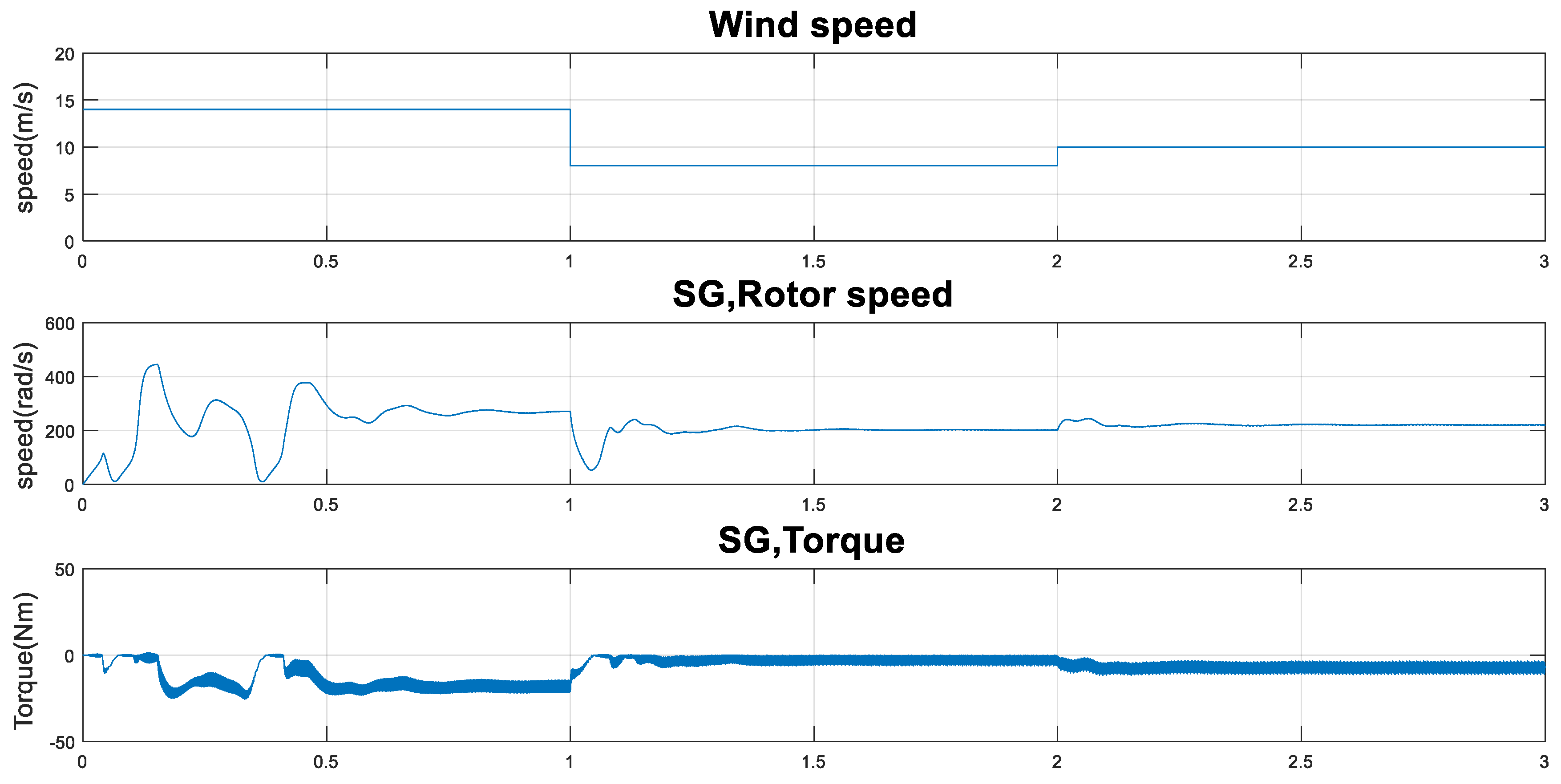
Taking into consideration IM rotor speed and IM load torque at different wind speed values, computer simulation outcomes have been illustrated to ensure the validity and effectiveness of our chosen system, which is considered for the purposes of research and study. The studied stand-alone wind/dynamic load with a battery store unit transformation frame and the suggested control technique is illustrated in Figure 3. The performance of the studied framework when the optimum PID control was considered as function of the three variables wind speed, IM load torque and IM rotor speed. Therefore, the optimal PID control based on MBA is depicted based on the simulation results as given in Figure 4, Figure 5 and Figure 6.
In detail, the following observations can be illustrated with the help of graphs.
Figure 4 presents that wind speed changes between the two different values 8.0 m/s and 14.0 m/s. It was observed that with higher velocity of the wind, the generator output torque of the WT gets larger; consequently, the value of the generator rotation speed increases, which leads to increasing values of generator stator current, voltage, and IM stator power.
Figure 5 illustrates that the desired velocity of IM increases from 20 rad/s to 30 rad/s at time 1.5 s. It was noticed that the actual velocity of IM tracks the reference velocity of IM using the vector control.
Also, Figure 6 shows that the IM reference load torque increases from zero Nm to 5.0 Nm at time 1.0 s. It was noticed that the actual IM load torque tracks the reference IM load torque based on the proposed vector control.
Therefore, the control procedure may be outlined as follows:
(a)
If Vdc tends to get larger because of the increase in the velocity of the wind:
The controller enters operation and differs from the operating cycle ratio of the load adapter to preserve Vdc at its reference value.
Simultaneously, the controller of the battery works to raise the charging current of the battery to keep any extra produced power and to maintain Vdc at their required value.
Accordingly, terminal voltage of the generator tends to be minimized and stabilized to the suitable value.
The field-oriented control adjusts the IM stator voltage in order for the IM velocity of the rotor to respond to the reference estimate.
If the DC-link voltage gets larger as a result of the increase in the velocity of the wind, the controllers will carry out an action that is opposite to those described above, as is clear from Figure 5.
(b)
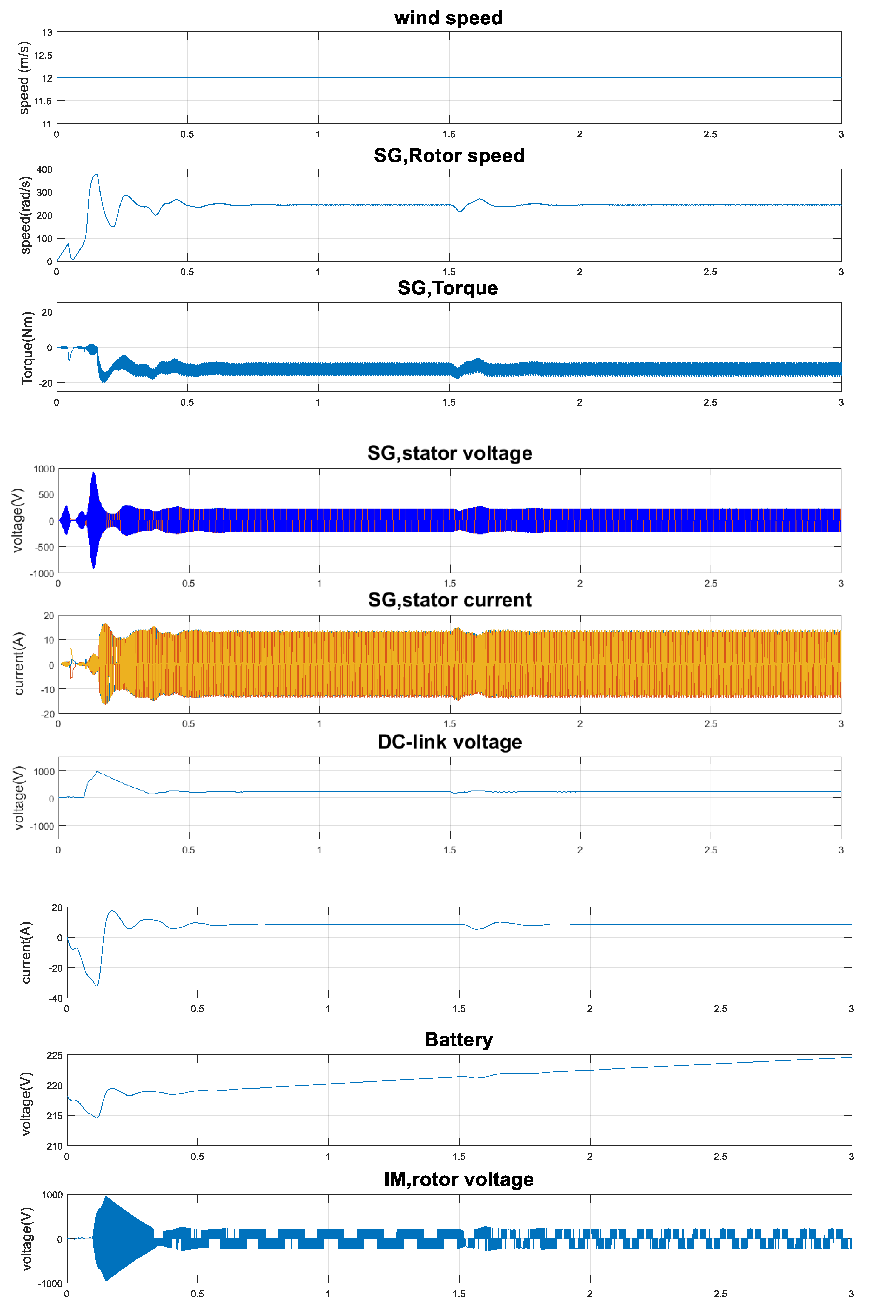
If the reference velocity of IM increases, the velocity of IM will get larger to be in line with the reference estimate when the motor stator frequency increases.
(c)
Similarly, if the IM reference load torque increases, the IM actual load torque will increase to a suitable level for the reference value.
The results obtained based on the proposed optimal PID control are compared with the obtained results using conventional PID control, as shown in Figure 7. From Figure 4 and Figure 7, one may notice that the system with the proposed optimal PID control has better performance than in the case of using classical PID control, as the high stator current harmonics and the IM rotor speed do not track the reference values. Also, it can be seen that the maximum overshoot is 8% and the steady state error in the rotor speed is zero when using the optimal control, while when using conventional PID, the maximum overshoot is 12% and the steady state error in the rotor speed is 7 rad/s.

7. Conclusions

This research proposes an optimum regulator on the basis of the mine blast algorithm for small-scale electrical power grid units. The given power network contains a hybrid wind-battery storage energy production system for feeding dynamic loads via an AC–DC–AC converter. Furthermore, this study assumes that the dynamic loads will be provided by a wind power output framework, and any decrease and/or additional electrical energy required by the loads will be made up for via the battery energy storage unit. In addition, it is expected that a portion of the wind-produced energy will be utilized when the wind speed is high in order to charge the battery. In this study, a self-excited induction generator is utilized and obtained using a wind turbine. The DC–AC converter is controlled dependent on an optimum PID controller as an external loop and a hysteresis current regulator as an internal loop for modifying the AC load voltage at its required level. Moreover, vector control is incorporated to modify the velocity and load torque of the induction motor. The numerical calculations are performed in Simulink/MATLAB programming, which is checked and established on dynamic load and wind speed varieties.-
In view of the obtained outcomes, one may make the following remarks:
-
The proposed hybrid generation wind/storage energy framework is qualified for feeding the dynamic loads taken into consideration.
-
The battery storage energy unit operates just to compensate the decrease in generated wind power and/or offer additional required energy using the load.
-
In addition, the considered controller is qualified for preserving load voltage at its reference estimate for dynamic loads with different parameters and/or variations in wind velocity.
-
The vector regulator of the induction motor is effective for following the velocity of the rotor speed in its desired value and load torque with 8% maximum overshoot, zero settling time and zero steady state error.
-
The system with the proposed optimal control has better performance than the case of applying conventional PID control.
-
As a future work, one could include the MPPT of wind power. In that case, all controllers would be changed, and more investigation and comparisons would be made.

Author Contributions

S.A.A. suggests the problem, modifies and designs the system, writes the basic equations and the mathematical formulation, carries out the computations after designing the software system. The whole work is corrected, improved and editing under the supervision of the S.S.A.

Funding

This research received no external funding.

Conflicts of Interest

The authors declare no conflict of interest.

Nomenclature

Aswept area
λtip speed ratio
ρair density
βblade pitch angle
RWT rotor radius
C p power coefficient
P t   wind turbine output power
T m   wind turbine output torque
V w   wind speed
ω t   the mechanical angular rotor speed of the wind turbine
Lstator inductance of PMSG
ω r   angular rotor speed of the PMSG
V s d   , V s q   d-q stator voltages of PMSG
i s d   , i s q   d-q stator currents of PMSG
λ m   flux linkage the PMSG
P g   pole pairs of the PMSG
T e g   electromagnetic torque of the PMSG
R s g   stator resistance of the PMSG
V b a t   battery output voltage
I D C ( r e c t . ) rectifier output current
V D C ( r e c t . ) rectifier output voltage
Dduty cycle ratio
I g   rms phase current of the PMSG
V g   rms phase voltage of the PMSG terminal
ffriction coefficient of the IM
R s   , R r   stator and rotor resistances of the IM
L s   , L r   stator and rotor main inductances of the IM
λ r   rotor leakage flux of the IM
L m   intrinsic self-inductance of the IM
λ d r   , λ q r   d- and q-axis of rotor leakage flux of the IM
i d r   , i q r   d- and q-axis of stator currents of the IM
ω s   rotor electrical speed of the IM
ω m   mechanical rotor speed of the IM
T e electromagnetic torque
rstator resistance
d d t   differential operator
L B , U B   lower and upper bounds of the problem
x o   a primary first shot point
Nsnumber of population
nrepetition number
μ   exploration factor
d n   vector contains the shrapnel distance for exploded mines
φ   angle of shrapnel pieces
x e   the best solution location
Fthe value of fitness function at the position x.
α   reduction factor
ITAEintegral time absolute error
IAEintegral absolute error
ISEintegral square error.
ITSEintegral time square error.
t s   time of simulation
XIndependent variable to be evaluated
U   Vector od dependent (control) variables
Ki(max), Ki(min)maximum and minimum limits of control parameters

References

  1. Kassem, A.M.; Abdelaziz, A.Y. Reactive power control for voltage stability of standalone hybrid wind–diesel power system based on functional model predictive control. IET Renew. Power Gener. 2014, 8, 887–899. [Google Scholar] [CrossRef]
  2. Mendis, N.; Muttaqi, K.M.; Perera, S. Management of battery-supercapacitor hybrid energy storage and synchronous condenser for isolated operation of PMSG based variable-speed wind turbine generating systems. IEEE Trans. Smart Grid 2004, 5, 944–953. [Google Scholar] [CrossRef]
  3. Mendis, N.; Muttaqi, K.M.; Sayeef, S.; Perera, S. Standalone Operation of Wind Turbine-Based Variable Speed Generators with Maximum Power Extraction Capability. IEEE Trans. Energy Convers. 2012, 27, 822–834. [Google Scholar] [CrossRef]
  4. Zhu, Y.; Tomsovic, K. Development of models for analyzing the load-following performance of microturbines and fuel cells. Electr. Power Syst. Res. 2002, 62, 1–11. [Google Scholar] [CrossRef]
  5. Delfino, B.; Fornari, F. Modeling and control of an integrated fuel cell/wind turbine system. In Proceedings of the IEEE PowerTech Conference, Bologna, Italy, 23–26 June 2003. [Google Scholar]
  6. De Battista, H.; Mantz, H.J.; Garelli, F. Power conditioning for a wind/hydrogen energy system. J. Power Sources 2006, 155, 478–486. [Google Scholar] [CrossRef]
  7. Barbir, F. PEM electrolysis for production of hydrogen from renewable energy sources. J. Sol. Energy 2005, 78, 661–669. [Google Scholar] [CrossRef]
  8. Gorgun, H. Dynamic modeling of a proton exchange membrane (PEM) electrolyzer. Int. J. Hydrogen Energy 2006, 31, 29–38. [Google Scholar] [CrossRef]
  9. Liu, C.; Chau, K.T.; Zhang, X. An efficient wind–photovoltaic hybrid generation system using doubly excited permanent-magnet brushless machine. IEEE Trans. Ind. Electron. 2010, 57, 831–839. [Google Scholar]
  10. Harwood, R.C.; Manoranjan, V.S.; Edwards, D.B. Lead–acid battery model under discharge with a fast splitting method. IEEE Trans. Energy Convers. 2011, 26, 1109–1117. [Google Scholar] [CrossRef]
  11. Świerczyński, M.; Teodorescu, R.; Rasmussen, C.N.; Rodriguez, P.; Vikelgaard, H. Overview of the energy storage systems for wind power integration enhancement. In Proceedings of the 2010 IEEE International Symposium on Industrial Electronics, Bari, Italy, 4–7 July 2010. [Google Scholar]
  12. Barote, L.; Marinescu, C. Storage analysis for stand-alone wind energy applications. In Proceedings of the 2010 12th International Conference on Optimization of Electrical and Electronic Equipment, Basov, Romania, 20–22 May 2010. [Google Scholar]
  13. Yang, L.S.; Liang, T.J. Analysis and implementation of a novel bidirectional DC–DC converter. IEEE Trans. Ind. Electron. 2012, 59, 422–434. [Google Scholar] [CrossRef]
  14. Chourasia1, A.; Srivastava, V.; Choudhary, A.; Praliy, S. Comparison study of vector control of induction motor using rotor flux estimation by two different methods. Int. J. Electron. Electr. Eng. 2014, 7, 201–206. [Google Scholar]
  15. Barote, L.; Marinescu, C.; Cirstea, M.N. Control structure for single-phase stand-alone wind-based energy sources. IEEE Trans. Ind. Electron. 2013, 60, 764–772. [Google Scholar] [CrossRef]
  16. Kassem, A.M. Neural control design for isolated wind generation system based on SVC and nonlinear autoregressive moving average approach. WSEAS Trans. Syst. 2012, 11, 39–49. [Google Scholar]
  17. Kassem, A.M.; Zaid, S.A. Optimal control of a hybrid renewable wind/fuel cell energy in micro grid application. In Proceedings of the 2017 Nineteenth International Middle East Power Systems Conference, Cairo, Egypt, 19–21 December 2017. [Google Scholar]
  18. Kassem, A.M. Modeling and robust control design of a stand-alone wind-based energy storage generation unit powering an induction motor variable-displacement pressure compensated pump. IET Renew. Power Gener. 2016, 10, 275–286. [Google Scholar] [CrossRef]
  19. Kassem, A.M. Fuzzy-logic based self-tuning PI controller for high-performance vector controlled induction motor fed by PV-generator. WSEAS Trans. Syst. 2013, 12, 22–31. [Google Scholar]
  20. Singh, G.; Kaur, P. Mine Blast Algorithm. Int. J. Res. Appl. Sci. Eng. Technol. 2018, 6, 519–525. [Google Scholar] [CrossRef]
  21. Sadollah, A.; Aahreininejada, A.; Eskandar, H.; Hamdi, M. Mine blast algorithm: A new population based algorithm for solving constrained engineering optimization problems. Appl. Soft Comput. 2013, 13, 2592–2612. [Google Scholar] [CrossRef]
  22. Erramia, Y.; Ouassaid, M.; Maaroufia, M. Control of a PMSG based wind energy generation system for power maximization and grid fault conditions. Energy Procedia 2013, 42, 220–229. [Google Scholar] [CrossRef]
  23. Bellarbi, S.; Koussa, D.S.; Djoudi, A. Sliding mode control for PMSG-based wind power system. J. Phys. Conf. Ser. 2018, 1081, 012012. [Google Scholar] [CrossRef]
  24. Lee, S.W.; Chun, K.H. Adaptive sliding mode control for PMSG wind turbine systems. Energies 2019, 12, 595. [Google Scholar] [CrossRef]
  25. Koumba, P.M.; Cheriti, A.; Doumbia, M.L.; Bouzid, A.M. Wind turbine control based on a permanent magnet synchronous generator connected to an isolated electrical network. In Proceedings of the 2017 IEEE Electrical Power and Energy Conference, Saskatoon, SK, Canada, 22–25 October 2017. [Google Scholar]
  26. Gam, O.; Abdelati, R.; Tankari, M.A.; Mimouni, M.F.; Lefebvre, G. Robust control strategies on the optimization of a wind turbine pumping system. Int. J. Renew. Energy Res. 2018, 8, 1641–1647. [Google Scholar]
  27. Verde, A.; Lastres, O.; Hernández, G.; Ibañez, G.; Verea, L.; Sebastian, P.J. A new method for characterization of small capacity wind turbines with permanent magnet synchronous generator: An experimental study. Heliyon 2018, 4, e00732. [Google Scholar] [CrossRef] [PubMed] [Green Version]
  28. Fateh, L.; Ahmed, O.; Amar, O.; Abdelhak, D.; Lakhdar, B. Modeling and control of a permanent magnet synchronous generator dedicated to standalone wind energy conversion system. Front. Energy 2016, 10, 155–163. [Google Scholar] [CrossRef]
  29. Ali, E.S. Speed Control of Induction Motor Supplied by Wind Turbine Using ICA. WSEAS Trans. Power Syst. 2016, 11, 261–270. [Google Scholar]
  30. Menghal, P.M.; Laxmi, A.J.; Anusha, D. Speed Control of Induction Motor using Fuzzy Logic Controller. i-Manag. J. Electr. Eng. 2014, 8, 21. [Google Scholar] [CrossRef]
  31. Fandi, G.; Ahmad, I.; Igbinovia, F.O.; Muller, Z.; Tlusty, J.; Krepl, V. Voltage regulation and power loss minimization in radial distribution systems via reactive power injection and distributed generation unit placement. Energies 2018, 11, 1399. [Google Scholar] [CrossRef]
  32. Rashid, M. Power Electronics Handbook, 2nd ed.; Elsevier Press: Amsterdam, The Netherlands, 2011. [Google Scholar]
Figure 1. Illustration diagram of the suggested autonomous WEC framework. Reproduced from Kassem [18], IET Renewable Power Generation: 2016.
Energies 12 02947 g001
Figure 2. Presents the flow chart for the mine blast algorithm. Reproduced from Kassem and Zaid [17], Nineteenth International Middle East Power Systems Conference (MEPCON): 2017.
Energies 12 02947 g002
Figure 3. Illustration diagram of autonomous wind/battery storage power transformation component providing IM with suggested control framework.
Energies 12 02947 g003
Figure 4. Effective reaction of autonomous wind/storage production component providing IM with the suggested control for step variations in velocity of the wind via both MBA and GA.
Energies 12 02947 g004aEnergies 12 02947 g004b
Figure 5. Effective reaction of autonomous wind/storage production component providing IM when the suggested control for step changes in velocity of IM.
Energies 12 02947 g005aEnergies 12 02947 g005b
Figure 6. Effective reaction of autonomous wind/storage production component providing IM when the suggested control for step changes in velocity of IM load torque.
Energies 12 02947 g006aEnergies 12 02947 g006b
Figure 7. Effective reaction of autonomous wind/storage production component providing IM with the conventional PID control for step variations in velocity of the wind.
Energies 12 02947 g007
Table 1. Optimal mine blast algorithm controlling parameters.
ParameterValue
A524.8
Ns120
Number of variables6
Max iteration100
Final distance0.0548
Number of function evaluations20,000

