Abstract
Flow-electrode-based capacitive deionization (FCDI) is a desalination process that uses electrostatic adsorption and desorption of ions onto electrode materials. It provides a continuous desalination flow with high salt removal performance and low energy consumption. Since lithium has been regarded as an essential element for the last few decades, the efficient production of lithium from the natural environment has been intensively investigated. In this study, we have extracted lithium ions from aqueous solution by using FCDI desalination. We confirmed that lithium and chloride ions could be continuously collected and that the salt removal rate depends on various parameters, including feed-flow rate and a feed saline concentration. We found that the salt removal rate increases as the feed-flow rate decreases and the feed salt concentration increases. Furthermore, the salt removal rate depends on the circulation mode of the feed solution (continuous feed stream vs. batch feed stream), which allows control of the desalination performance (higher capacity vs. higher efficiency) depending on the purpose of the application. The salt removal rate was highest, at 215.06 μmol/m−2s−1, at the feed rate of 3 mL/min and the feed concentration of 100 mg/L. We believe that such efficient and continuous extraction of lithium chloride using FCDI desalination can open a new door for the current lithium-production industry, which typically uses natural water evaporation.
1. Introduction
Lithium is the one of the most important elements in various industries, in particular, rechargeable battery systems, because of its high energy density and electrochemical potential. Therefore, as the global energy-storage markets greatly expand, the demand for lithium has grown continuously over the past few decades. In particular, the rapid growth of the electric vehicle industry significantly accelerates such trend. An increase of 8–11% in annual lithium demand is expected. [1,2]. As a result, the average global price of lithium has also significantly increased for the last few years ($14,000–17,000 per ton) [3]. For now, around 70% of global lithium production has been attained from the salt lakes located in only few countries. Such limited geographical distribution of lithium sources might result in serious lithium supply issues. Furthermore, lithium is collected typically by evaporation with solar radiation during several months, which is inefficient and time consuming [4]. The greatest sources of lithium exist in seawater and brackish water. Therefore, lithium extraction from brackish water and seawater has received much attention for economical and stable lithium production [5,6,7,8,9,10,11,12,13]. Mantia group introduced lithium recovery from brines using ion exchange process [12,13]. Xiang group investigated the lithium extraction using lithium-ion selective capturing layered double hydroxides (LiAl-LDH) [14]. Yoshizuka group also reported selective lithium adsorption using manganese oxide. However, most lithium adsorption processes are very slow [15]. Capacitive deionization (CDI) has been regarded as a fascinating technology for desalination. It operates based on the electrostatic adsorption and desorption of charged ions onto -porous electrode materials. CDI cells are composed of an anode and cathode sandwiched between current collectors. The separator acting as a feed stream channel is located between the two electrode layers. When a potential (typically less than 1.2 V) is applied to the current collectors, positively and negatively charged ions migrate from the feed solution and are adsorbed onto the electric double layer of porous carbon electrodes by electrostatic interaction. Since ions are physically stored onto the electrodes instead of redox reaction, such ion removal process is very fast. Furthermore, desalination using CDI is highly energy efficient (less than 1 kWh/m3) compared to conventionally used reverse osmosis (RO: 2–4 kWh/m3) or multistage flash distillation (MSF: 70–80 kWh/m3) [16,17,18,19]. In addition, the CDI cell is simple in configuration, and desalination using CDI is very environmentally friendly. Therefore, it has been investigated intensively for the last two decades for removal of sodium chloride ions from brackish water. Many researchers have developed CDI desalination systems in terms of theories, electrode materials, and various cell configurations [17,18,19,20,21,22,23,24,25,26,27,28]. Furthermore, in principle, not only sodium chloride but also various kinds of charged ions can be extracted [29,30,31]. However, CDI has inevitable drawbacks coming from its working mechanism. After the full saturation of -porous carbon electrodes with charged ions, the electrodes can no longer hold any more ions. Therefore, the adsorbed ions need to be eliminated by applying zero or reverse potential. During such discharging, more salinized effluent is generated, which must be handled separately to obtain only fresh desalinated water, which results in discontinuous desalination as well as a low salt removal capacity. Due to such limitations of conventional CDI desalination, the salt removal performance has to be sacrificed, making its main target desalination of brackish water with a salt concentration of only few grams per liter. In order to solve such inherent disadvantages of the CDI system, desalination using CDI based on flow electrodes (FCDI) has been investigated [21,26,32,33,34]. When a flow anode and cathode circulate the FCDI cell, ions are adsorbed onto the electric double layer of -porous electrode carbons and flow out together. At the same time, fresh electrodes are continuously supplied to the cell, which allows them to capture more ions from the feed stream. By such circulation of flowable electrodes, desalination can be carried out continuously as long as the potential is applied to the FCDI cell, which therefore does not need to apply a reverse potential to remove ions from the -porous carbon electrodes. The FCDI also provides much higher salt removal capacity than the conventional CDI that uses fixed electrodes does. Like the CDI system, FCDI can also be used for the removal of types of ions other than sodium-chloride ions.
Herein, we present a continuous extraction of LiCl ions from aqueous solution by using FCDI desalination. Our results confirmed that LiCl could be successfully collected from a feed saline solution with various concentrations. Depending on the feed concentrations, ranging from 1 to 100 mg/L, the FCDI cell showed different salt removal rates. At the highest salt concentration (100 mg/L), it had the highest salt removal efficiency, of around 91.7%, compared to that of the lower feed concentrations. Furthermore, our results showed that the salt removal performance is also strongly affected by the feed rate. As the feed rate decreased from 9 to 3 mL/min while other experimental conditions were fixed, both salt removal rate and salt removal efficiency increased. Furthermore, in order to optimize the maximum removal of LiCl from aqueous solution, two different desalination modes were applied (continuous feed stream mode vs. batch feed stream mode). In a continuous feed stream, the continuous effluent with various salt removal efficiencies could be realized, whereas in a batch feed stream, a more highly desalinated feed solution could be obtained. Such desalination operating in different modes allows control of the desalination performance (higher desalination capacity vs. higher desalination efficiency) depending on the purpose for its use.
2. Materials and Methods
2.1. Materials
Lithium chloride was purchased from Sigma-Aldrich (St. Louis, MO, USA). Porous activated carbons (MSP-20 with a diameter of around 9 μm and the specific surface area of 2360 m2/g) were purchased from Kansai Coke & Chemicals Co (Hyogo, Japan). They were filtered by a 10 μm sieve before the preparation of the flow electrode slurry. Cationic exchange and anionic exchange membranes were purchased from ASTOM Corporation (Neosepta CMX & AMX) and used without further modification. Deionized water (18 MΩ cm−2) was obtained from the Human Power II+ (Human Corporation, Seoul, Korea) purification system.
2.2. FCDI Cell Configuration
For the preparation of flow-electrode slurry, nanoporous activated carbons (20 wt%) were added in deionized water and stirred for 30 min. Then, lithium chloride (2.5 wt%) was added to the flow-electrode slurry as utilized by Yang et al. [35]. During FCDI desalination, the slurry was continuously stirred using a magnetic bar. The FCDI cell consists of a pair of polycarbonate-based supporting plates and a pair of graphite current collectors that include flow-electrode channels (1 mm width and 1 mm depth). The effective area of the electrode channels was 12.7 cm2 per flow anode and flow cathode. Cationic and anionic exchange membranes were sandwiched in between the current collectors, and a nylon-based spacer was located in the middle of the cell, as shown in Figure 1. Flow anode and cathode slurry was continuously introduced into the inlet of each flow channel and circulated in the FCDI cell during the whole desalination operation with a flow rate of 25 mL/min, using a peristaltic pump (Miniplus 3, Gilson, Inc., Middleton, WI, USA). A LiCl aqueous solution with concentrations from 1 to 100 mg/L and 5 g/L was also supplied to the inlet and drained from the outlet through the spacer channel, with feed-flow rates of 3, 6, and 9 mL/min by using a peristaltic pump. Two different circulation modes of the feed stream were used.
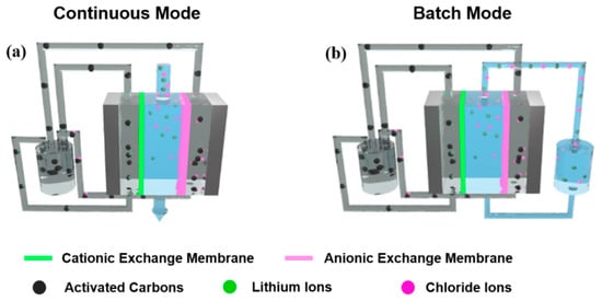
Figure 1.
Schematics of the experimental setup of LiCl extraction using flow-electrode-based capacitive deionization (FCDI) in (a) continuous and (b) batch mode.
2.3. Assessment of FCDI Desalination Performance
Desalination was performed by applying a constant potential of 1.2 V (potentiostat mode) using a potentiostat (ZIVE MP2A, Wonatech, Korea) for a controlled time period. The conductivity of the effluent stream was simultaneously measured by a conductivity meter (DS-70, Horiba, Japan). The salt concentration was calculated from the measured conductivity from the LiCl concentration-conductivity reference curve (Figure S1). The salt removal efficiency was calculated by means of the following equation,
where and are the initial and final salt concentration. Current density was calculated from the measured current divided by the effective area of the flow-electrode channel. The salt removal rate was calculated from the amount of removed salt divided by the unit area and unit time as μmoL m−2 s−1.
3. Results and Discussions
3.1. FCDI LiCl Desalination in a Continuous Mode
Figure 1 compares the experimental setup for FCDI desalination in continuous and batch modes. For both modes, the FCDI cell has an identical configuration, with a separator in the center acting as a channel for the feed solution. The cationic and anionic exchange membranes are placed outside the separator. Graphite-based current collectors that include channels for the flowable anode and cathode are located on the outside of the ion-exchange membranes. The flow anode and cathode were continuously pumped into the inlet of the current collectors and pumped out, then were drained into a single container and recirculated in the FCDI cell during the desalination operation. With application of a cell potential of 1.2 V, cationic Li+ and anionic Cl− ions were electrostatically migrated through the ion-exchange membranes and adsorbed in the electric double layer of flow electrodes. The flow anode and cathode saturated with Li and Cl ions were combined in a container and thus neutralized, which results in a desorption of the ions from the carbon electrodes. At this time, the salt ions were continuously accumulated in a container. Then, fresh flow electrodes were newly pumped into the FCDI cell so that they could capture other ions from the feed stream, allowing continuous desalination even when using a fixed amount of flow carbon electrodes. The contact area between flow electrodes and feed saline solution was 12.7 cm2. As the contact area increased, the residence time of the feed saline solution also increased at the same feed rate, which provided charged ions with more chances to be eliminated. Therefore, increased FCDI cell size allowed higher salt removal performance and capacity.
For the continuous mode, the feed solution was transported through a separator, and the conductivity of the drained effluent was measured in real time as shown in Figure 1a. Therefore, feed water passed through the FCDI cell only one time and thus allowed the continuous production of desalinated water from the outlet of the FCDI cell. On the other hand, for a batch mode, feed saline solution drained from the FCDI cell was collected in a container and introduced to the FCDI cell again. Therefore, a fixed amount of saline water (100 mL) continuously circulated through the FCDI cell during desalination as shown in Figure 1b, allowing the saline water to pass the desalination cell multiple times, resulting in a more highly desalinated effluent stream.
Figure 2 shows the variation in the current and LiCl concentration of the drained effluent in the continuous desalination mode. Various feed concentrations of LiCl solution were investigated at the fixed feed-flow rate of 3 mL/min. When the cell potential of 1.2 V was applied to the FCDI cell, the current was measured which originated from the separation and migration of salt ions from the feed stream to the flow electrodes, as shown in Figure 2a. As the desalination proceeded, the current was maintained at a constant value for the entire cell operation. Such constant current values indicate that ions are continuously removed from the saline water without the additional rinsing step typically required for conventional CDI desalination using fixed electrodes. It is the distinct advantage of continuous FCDI desalination. At the highest LiCl concentration of 100 mg/L, it showed the highest current of around 7.9 mA while they exhibited lower currents compared to that of 100 mg/L for the salt concentrations of 1 and 10 mg/L. Since the number of ions existing in the feed stream with a higher salt concentration is larger than those with a relatively low salt concentration, more ions could be transported from the feed stream to the electrode slurry. It results in the higher current value at the higher feed concentration. The corresponding variation in LiCl concentration of the effluent stream is shown in Figure 2b. Y-axis indicates the ratio of salt concentration of effluent to that of the feed stream, representing how much salts were collected during FCDI operation. As the salt ions are extracted from the feed solution, the salt concentration dropped after the first 10 min and maintained a certain value during the entire FCDI operation. For the highest salt concentration of 100 mg/L, the salt removal efficiency was the highest, at around 91.7%, whereas those of 1 and 10 mg/L had efficiencies of around 85–87%. Such a trend in salt removal efficiency at the various salt concentrations corresponded well with the change in the current. Those results indicate that more than 85% of LiCl existing in the aqueous solution could be continuously collected even in a broad range of salt concentration ranging from 1 to 100 mg/L. It showed similar trends as the feed rate increased to 6 and 9 mL/min as shown in Figures S2 and S3.

Figure 2.
Variation in (a) current and (b) LiCl concentration in the effluent stream as a function of time during FCDI desalination under various feed concentrations at a feed rate of 3 mL/min.
In order to realize the ideal FCDI operational condition for the removal of LiCl, FCDI desalination was performed at the various feed rates while the salt concentration was fixed at 100 mg/L. As the feed rate increased from 3 to 9 mL/min, the current also increased, from around 7.8 to 13.6 mA, which indicates that more ions are separated and adsorbed onto the flow electrode with a higher feed rate. Since, for the identical feed salt concentration, more ions flow through the water channel (separator) as the feed rate increases, there are more possibilities for ions to be transported into the channel of flow electrodes. Therefore, the current increased with a higher feed rate. On the other hand, the salt removal efficiency decreased from 91.7 to 80.3 and to 66.8% as the feed rate increased from 3 to 6 and to 9 mL/min, respectively, as shown in Figure 3b. For the feed rate of 9 mL/min, the concentration started to drop after the first 8.3 min, but it took 9.6 and 10.8 min for the feed rate of 6 and 3 mL/min, respectively. Since the feed solution circulated through the FCDI cell faster, the required time for the measurement of salt conductivity decreased with a higher feed rate. At the higher feed rate, as described above, more ions flowed through the FCDI cell per unit time and the number of eliminated ions also increased, as was expressed by the increase in current value, as shown in Figure 3a. However, when considering the salt removal efficiency rather than the absolute number of removed ions, the situation is somewhat different. The ratio of the number of eliminated ions to the number of ions that flow through the FCDI cell decreased as the feed rate increased, which indicates that even though more ions could be removed, the number of ions that are not captured by the carbon electrodes increases more significantly. Furthermore, in order to confirm the long-term stability of FCDI desalination system, we have performed the LiCl extraction for 24 h as shown in Figure S4. It did not show any significant change in the current and conductivity during the whole FCDI operation. In order to prevent redox reactions of carbon electrodes such as carbon oxidation or water electrolysis of slurry electrode and feed water solution, the applied cell potential of 1.2 V was utilized in the present desalination system. Furthermore, as described earlier, when the anode and cathode carbon electrodes those electrostatically adsorb the charged ions are combined in one container, they are neutralized. Therefore, the charged ions are released from the carbon electrodes, which enables the fresh electrodes to introduce into the FCDI cell. Therefore, such FCDI desalination process can be continuously operated in principle as long as the potential is applied to the FCDI cell without significant degradation in salt removal performance. Such stable long-term operation performance is similar to the distinct advantage of supercapacitor system.
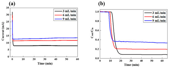
Figure 3.
Variation in (a) LiCl concentration in the effluent stream and (b) current as a function of time during FCDI desalination under various feed rates at a feed concentration of 100 mg/L.
Figure 4 summarizes the desalination parameters, including salt removal efficiency, current density, and salt removal rate depending on the feed concentration (1, 10, and 100 mg/L) and feed rate (3, 6, and 9 mL/min). Salt removal rate represents the overall salt removal performance of the FCDI cell per unit of effective surface area and unit time. Salt removal rate systematically increased as the feed concentration increased for all feed rates. Furthermore, it increased as the feed rate decreased. The salt removal efficiency generally decreased at the higher feed rate. Overall, the salt removal rate was highest, at 215.06 μmol/m−2s−1, at the feed rate of 3 mL/min and the feed concentration of 100 mg/L.
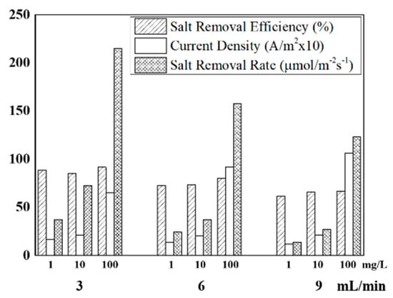
Figure 4.
Desalination parameters under various FCDI operating conditions.
3.2. FCDI LiCl Desalination in a Batch Mode
In order to optimize the salt removal performance for practical use, we compared the salt removal behavior in a continuous mode (Figure 1a) and batch mode (Figure 1b). Figure 5a,b show the variation in current and concentration in a continuous feed-flow mode with various feed rates (1, 3, and 6 mL/min) at the feed concentration of 5 g/L. The other experimental conditions including cell potential, electrode concentration, and rate were fixed as in the previous experiments.
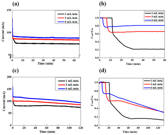
Figure 5.
LiCl extraction in the FCDI process in (a,b) a feed-flow continuous and (c,d) batch mode; (a,c) are the variation in current and (b,d) are the variation in the conductivity of the effluent stream.
As shown in Figure 5a, as the flow rate increased from 1 to 3 and to 6 mL/min, the current increased from 75 to 84 and to 89 mA, respectively. Those current values are all much higher than those observed in Figure 2, because of the higher feed concentration of 5 g/L. As the feed concentration and feed-flow rate increase, the more ions can be migrated and adsorbed onto the flow electrode, which allows higher current densities. At this time, the salt removal efficiency also strongly depends on the feed-flow rate, as shown in Figure 5b. As the feed-flow rate increases up to 6 mL/min, the salt removal efficiency decreases from 78.2 to 33.8 and to 18.8%, respectively, as shown in Table 1. In this continuous feed-flow mode, the initial time for the salt concentration to drop increases with the lower feed-flow rate. However, once the salt concentration decreases, it remains constant during the FCDI process, which indicates that the desalinated effluent with a constant salt removal efficiency can be continuously obtained. On the other hand, LiCl desalination in a batch feed-flow mode was also carried out, as shown in Figure 5c,d. The current densities for the feed rates of 1, 3, and 6 mL/min gradually decreased as the FCDI desalination proceeded (Figure 5c). In this condition, the initial feed concentration is identical with that of the continuous mode (5 g/L). However, they gradually decrease, because the feed solution is continuously circulated and desalinated in the FCDI cell. The LiCl concentrations are also gradually reduced with increasing operation time, as shown in Figure 5d. The concentrations drop to a certain point and start to decrease gradually, with different slopes depending on the feed rate. Since the salt removal efficiency depends on the feed-flow rates, the initial drop points of salt concentration have different values, of 0.15, 0.57, and 0.74 for 1, 3, and 6 mL/min, respectively. That is, the efficiency increased with the lower feed rate. However, after those points, the salt concentration decreases more as the feed-flow rate increases. Such results confirmed that for the batch feed-flow mode, the salt concentration can be precisely controlled by FCDI operating time, and a highly desalinated solution also can be achieved. Table 1 shows the salt removal behavior under both modes for 2 h of FCDI operation. For the batch mode, the total amount of removed LiCl is generally lower than that of the continuous mode. However, the salt removal efficiency calculated after 2 h of FCDI operation is higher than that of the continuous mode, which indicates that, depending on the purpose of the application, two different feed-flow modes can be used. For example, the continuous mode generates a higher salt removal capacity, but the batch mode provides higher salt removal efficiency.

Table 1.
Desalination parameters in various FCDI experimental conditions.
4. Conclusions
We have investigated the continuous extraction of LiCl ions from aqueous solution by capacitive deionization based on flow electrodes. Unlike the typical CDI using fixed electrodes, LiCl could be continuously collected without the need for a rinsing process, which provides a much higher salt removal capacity with less energy consumption than reverse osmosis or multi-stage flash distillation. Various desalination parameters, including feed rate, feed concentration, and feed circulation mode were systematically investigated. Our results confirmed that the salt removal efficiency increases as the feed rate decreases as well as at the higher feed concentration. The salt removal rate was highest, at 215.06 μmol/m−2s−1, at the feed rate of 3 mL/min and the feed concentration of 100 mg/L. Furthermore, two different feed circulation modes were compared to find the ideal salt removal performance. As a result, we found that for the batch feed-flow mode, much highly desalinated feed could be obtained, whereas for the continuous feed-flow mode, much more LiCl was extracted. Hence the two different operational modes can be used as needed. For now, there are some issues that need to be further developed for application to the practical lithium production process. For example, the salt removal capacity needs to be more enhanced. Furthermore, energy consumption needs to be decreased. CDI desalination consumes lower energy compared to reverse osmosis and multi-stage distillation. However, it anyways needs energy for desalination process, whereas natural evaporation with solar radiation which is the current lithium production method requires only tiny energy consumption (Table S1). Nevertheless, we believe that our approach can open a new door for the current LiCl production market. Furthermore, it can be extended to extraction or removal of other valuable elements from lakes, brackish water, or seawater in a highly efficient and cost-effective way.
Supplementary Materials
The following are available online at https://www.mdpi.com/1996-1073/12/15/2913/s1. Figure S1. Changes in conductivity as a function of LiCl concentration. Figure S2. Variation in (a) current and (b) LiCl concentration in the effluent stream as a function of time during FCDI desalination under various feed concentrations at a feed rate of 6 mL/min. Figure S3. Variation in (a) current and (b) LiCl concentration in the effluent stream as a function of time during FCDI desalination under various feed concentrations at a feed rate of 9 mL/min. Figure S4. Variation in current and LiCl concentration in the effluent stream as a function of time during FCDI desalination at a feed rate of 3 mL/min and a feed concentration of 100 mg/L. Table S1. Comparison of the FCDI process with other Li extraction technologies.
Author Contributions
Conceptualization, Y.C., P.S.J., and H.Y.; investigation, H.L. and C.-Y.Y.; data curation, T.K.P. and W.A.; writing, original draft preparation, Y.H., H.B.J., Y.C.; writing, review and editing, Y.C.; funding acquisition, Y.C.
Funding
This work was supported by the Korea Institute of Energy Technology Evaluation and Planning (KETEP) and the Ministry of Trade, Industry & Energy(MOTIE) of the Republic of Korea (No. 20184030202130). This work was also supported by the National Research Foundation of Korea (NRF) grant funded by the Korea government (MSIT) (No. 2018R1C1B5085456).
Conflicts of Interest
The authors declare no conflict of interest.
References
- Swain, B. Recovery and recycling of lithium: A review. Sep. Purif. Technol. 2017, 172, 388–403. [Google Scholar] [CrossRef]
- Ebensperger, A.; Maxwell, P.; Moscoso, C. The lithium industry: Its recent evolution and future prospects. Resour. Policy 2005, 30, 218–231. [Google Scholar] [CrossRef]
- Martin, G.; Rentsch, L.; Höck, M.; Bertau, M. Lithium market research–global supply, future demand and price development. Energy Storage Mater. 2017, 6, 171–179. [Google Scholar] [CrossRef]
- Vikström, H.; Davidsson, S.; Höök, M. Lithium availability and future production outlooks. Appl. Energy 2013, 110, 252–266. [Google Scholar] [CrossRef]
- Shi, W.; Liu, X.; Ye, C.; Cao, X.; Gao, C.; Shen, J. Efficient lithium extraction by membrane capacitive deionization incorporated with monovalent selective cation exchange membrane. Sep. Purif. Technol. 2019, 210, 885–890. [Google Scholar] [CrossRef]
- Ryu, T.; Lee, D.H.; Ryu, J.C.; Shin, J.; Chung, K.S.; Kim, Y.H. Lithium recovery system using electrostatic field assistance. Hydrometallurgy 2015, 151, 78–83. [Google Scholar] [CrossRef]
- Bryjak, M.; Siekierka, A.; Kujawski, J.; Smolińska-Kempisty, K.; Kujawski, W. Capacitive Deionization for Selective Extraction of Lithium from Aqueous Solutions. J. Membr. Sep. Technol. 2015, 4, 110–115. [Google Scholar] [CrossRef]
- Guo, Z.Y.; Ji, Z.Y.; Chen, Q.B.; Liu, J.; Zhao, Y.Y.; Li, F.; Liu, Z.Y.; Yuan, J.S. Prefractionation of LiCl from concentrated seawater/salt lake brines by electrodialysis with monovalent selective ion exchange membranes. J. Clean. Prod. 2018, 193, 338–350. [Google Scholar] [CrossRef]
- Tsuchiya, S.; Nakatani, Y.; Ibrahim, R.; Ogawa, S. Highly Efficient Separation of Lithium Chloride from Seawater. J. Am. Chem. Soc. 2002, 124, 4936–4937. [Google Scholar] [CrossRef]
- Romero, V.C.E.; Tagliazucchi, M.; Flexer, V.; Calvo, E.J. Sustainable Electrochemical Extraction of Lithium from Natural Brine for Renewable Energy Storage. J. Electrochem. Soc. 2018, 165, A2294–A2302. [Google Scholar] [CrossRef]
- Hoshino, T. Innovative lithium recovery technique from seawater by using world-first dialysis with a lithium ionic superconductor. Desalination 2015, 359, 59–63. [Google Scholar] [CrossRef]
- Trócoli, R.; Erinmwingbovo, C.; La Mantia, F. Optimized lithium recovery from brines by using an electrochemical ion-pumping process based on λ-mno2 and nickel hexacyanoferrate. Chem Electro Chem 2017, 4, 143–149. [Google Scholar] [CrossRef]
- Palagonia, M.S.; Brogioli, D.; La Mantia, F. Influence of Hydrodynamics on the Lithium Recovery Efficiency in an Electrochemical Ion Pumping Separation Process. J. Electrochem. Soc. 2017, 164, E586–E595. [Google Scholar] [CrossRef]
- Sun, Y.; Guo, X.; Hu, S.; Xiang, X. Highly efficient extraction of lithium from salt lake brine by LiAl-layered double hydroxides as lithium-ion-selective capturing material. J. Energy Chem. 2019, 34, 80–87. [Google Scholar] [CrossRef]
- Park, J.; Sato, H.; Nishihama, S.; Yoshizuka, K. Lithium Recovery from Geothermal Water by Combined Adsorption Methods. Solvent Extr. Ion. Exch. 2012, 30, 398–404. [Google Scholar] [CrossRef]
- Zhao, R.; Biesheuvel, P.M.; Van Der Wal, A. Energy consumption and constant current operation in membrane capacitive deionization. Energy Environ. Sci. 2012, 5, 9520. [Google Scholar] [CrossRef]
- Lee, J.; Kim, S.; Kim, C.; Yoon, J. Hybrid capacitive deionization to enhance the desalination performance of capacitive techniques. Energy Environ. Sci. 2014, 7, 3683–3689. [Google Scholar] [CrossRef]
- Suss, M.E.; Porada, S.; Sun, X.; Biesheuvel, P.M.; Yoon, J.; Presser, V. Water desalination via capacitive deionization: What is it and what can we expect from it? Energy Environ. Sci. 2015, 8, 2296–2319. [Google Scholar] [CrossRef]
- Ramachandran, A.; Oyarzun, D.I.; Hawks, S.A.; Stadermann, M.; Santiago, J.G. High water recovery and improved thermodynamic efficiency for capacitive deionization using variable flowrate operation. Water Res. 2019, 155, 76–85. [Google Scholar] [CrossRef]
- Zhang, C.; He, D.; Ma, J.; Tang, W.; Waite, T.D. Faradaic reactions in capacitive deionization (CDI)–problems and possibilities: A review. Water Res. 2018, 128, 314–330. [Google Scholar] [CrossRef]
- Cho, Y.; Yoo, C.Y.; Lee, S.W.; Yoon, H.; Lee, K.S.; Yang, S.; Kim, D.K. Flow-electrode capacitive deionization with highly enhanced salt removal performance utilizing high-aspect ratio functionalized carbon nanotubes. Water Res. 2019, 151, 252–259. [Google Scholar] [CrossRef]
- Hand, S.; Shang, X.; Guest, J.S.; Smith, K.C.; Cusick, R.D. Global Sensitivity Analysis to Characterize Operational Limits and Prioritize Performance Goals of Capacitive Deionization Technologies. Environ. Sci. Technol. 2019, 53, 3748–3756. [Google Scholar] [CrossRef]
- Santangelo, S.; Pantò, F.; Triolo, C.; Stelitano, S.; Frontera, P.; Fernández-Carretero, F.; Rincon, I.; Azpiroz, P.; García-Luis, A.; Belaustegui, Y. Evaluation of the electrochemical performance of electrospun transition metal oxide-based electrode nanomaterials for water CDI applications. Electrochim. Acta 2019, 309, 125–139. [Google Scholar] [CrossRef]
- Wang, K.; Liu, Y.; Ding, Z.; Li, Y.; Lu, T.; Pan, L. Metal–organic-frameworks-derived NaTi2(PO4)3/carbon composites for efficient hybrid capacitive deionization. J. Mater. Chem. A 2019, 7, 12126–12133. [Google Scholar] [CrossRef]
- Yasin, A.S.; Mohamed, A.Y.; Mohamed, I.M.A.; Cho, D.Y.; Park, C.H.; Kim, C.S. Theoretical insight into the structure-property relationship of mixed transition metal oxides nanofibers doped in activated carbon and 3d graphene for capacitive deionization. Chem. Eng. J. 2019, 371, 166–181. [Google Scholar] [CrossRef]
- Zhang, C.; He, D.; Ma, J.; Tang, W.; Waite, T.D. Comparison of faradaic reactions in flow-through and flow-by capacitive deionization (CDI) systems. Electrochim. Acta 2019, 299, 727–735. [Google Scholar] [CrossRef]
- Suss, M.E.; Biesheuvel, P.; Baumann, T.F.; Stadermann, M.; Santiago, J.G. In Situ Spatially and Temporally Resolved Measurements of Salt Concentration between Charging Porous Electrodes for Desalination by Capacitive Deionization. Environ. Sci. Technol. 2014, 48, 2008–2015. [Google Scholar] [CrossRef]
- Porada, S.; Zhao, R.; Van Der Wal, A.; Presser, V.; Biesheuvel, P. Review on the science and technology of water desalination by capacitive deionization. Prog. Mater. Sci. 2013, 58, 1388–1442. [Google Scholar] [CrossRef]
- Kim, S.; Yoon, H.; Shin, D.; Lee, J.; Yoon, J. Electrochemical selective ion separation in capacitive deionization with sodium manganese oxide. J. Colloid Interface Sci. 2017, 506, 644–648. [Google Scholar] [CrossRef]
- Lee, D.-H.; Ryu, T.; Shin, J.; Ryu, J.C.; Chung, K.S.; Kim, Y.H. Selective lithium recovery from aqueous solution using a modified membrane capacitive deionization system. Hydrometallurgy 2017, 173, 283–288. [Google Scholar] [CrossRef]
- Kim, J.; Jain, A.; Zuo, K.; Verduzco, R.; Walker, S.; Elimelech, M.; Zhang, Z.; Zhang, X.; Li, Q. Removal of calcium ions from water by selective electrosorption using target-ion specific nanocomposite electrode. Water Res. 2019, 160, 445–453. [Google Scholar] [CrossRef]
- Jeon, S.I.; Park, H.R.; Yeo, J.G.; Yang, S.; Cho, C.H.; Han, M.H.; Kim, D.K. Desalination via a new membrane capacitive deionization process utilizing flow-electrodes. Energy Environ. Sci. 2013, 6, 1471. [Google Scholar] [CrossRef]
- Cho, Y.; Lee, K.S.; Yang, S.; Choi, J.; Park, H.R.; Kim, D.K. A novel three-dimensional desalination system utilizing honeycomb-shaped lattice structures for flow-electrode capacitive deionization. Energy Environ. Sci. 2017, 10, 1746–1750. [Google Scholar] [CrossRef]
- Lee, K.S.; Cho, Y.; Choo, K.Y.; Yang, S.; Han, M.H.; Kim, D.K. Membrane-spacer assembly for flow-electrode capacitive deionization. Appl. Surf. Sci. 2018, 433, 437–442. [Google Scholar] [CrossRef]
- Yang, S.; Choi, J.; Yeo, J.G.; Jeon, S.I.; Park, H.R.; Kim, D.K. Flow-Electrode Capacitive Deionization Using an Aqueous Electrolyte with a High Salt Concentration. Environ. Sci. Technol. 2016, 50, 5892–5899. [Google Scholar] [CrossRef]


© 2019 by the authors. Licensee MDPI, Basel, Switzerland. This article is an open access article distributed under the terms and conditions of the Creative Commons Attribution (CC BY) license (http://creativecommons.org/licenses/by/4.0/).