Article

Electromechanical Transient Modeling and Control Strategy of Decentralized Hybrid HVDC Systems

1
College of Electrical Engineering, Zhejiang University, Hangzhou 310027, China
2
Department of Electrical Engineering and Computer Science, The University of Tennessee, Knoxville, TN 37201, USA
3
China Southern Grid Power Dispatching and Control Center, Guangzhou 510000, China
*
Author to whom correspondence should be addressed.
Energies 2019, 12(15), 2856; https://doi.org/10.3390/en12152856
Submission received: 11 July 2019 / Revised: 22 July 2019 / Accepted: 23 July 2019 / Published: 24 July 2019

Abstract

:
This paper studies the electromechanical transient model and the control strategy of line commutated converter (LCC) and modular multilevel converter (MMC) based decentralized hybrid High Voltage Direct Current (HVDC) Transmission systems. The decentralized hybrid HVDC system is a new type of topology, and the related electromechanical transient model and control strategy have not been studied well. In this paper, the electromechanical transient model of a decentralized hybrid HVDC system is devloped through mathematical deduction. This model can be easily implemented in electromechanical transient simulation software and meet the time domain simulation requirements of large-scale systems. Then, in order to ensure the safe absorption of the DC power under various conditions, an optimal power flow model considering the decentralized hybrid HVDC system is proposed. Finally, the electromechanical transient model proposed in this paper is verified by the electromagnetic transient model, and the control strategy is validated in a modified New England 39-bus system.

Graphical Abstract

1. Introduction

In China, bulk power High Voltage Direct Current (HVDC) transmissions play an important role in the West-to-East Power Transmission Project [1]. In general, a converter station adopts a centralized connection mode, which means that all converters in the station are connected to one AC bus. But with the increasing transmission power of an HVDC system, the centralized connection mode requires a strong AC network to absorb the DC power [2,3]. Moreover, when some AC faults occur, an HVDC system with the centralized connection mode may lose all power, which endangers the stability of the AC system. Therefore, a decentralized connection mode that different converters in a station are connected to different AC buses is a good way to solve these problems [4,5]. The commutation failure of a line commutated converter (LCC) inverter will threaten the stability of receiving power grids [6], whereas a commutation failure will not occur in a modular multilevel converter (MMC). However, an MMC is much more expensive than an LCC. Therefore, the LCC-MMC hybrid HVDC system has received wide attention in recent years [7,8]. In addition, the LCC and half bridge sub-module MMC hybrid HVDC system is the focus of this paper. Electromechanical transient models and control strategies of the centralized hybrid HVDC system have previously been studied [9,10]. However, as a new HVDC topology, the decentralized hybrid HVDC system needs further study.
Electromechanical transient models are essential for planning and dynamic analysis of large scale AC/DC systems. In China, a decentralized hybrid HVDC system project is in the planning stages. Because of the large scale of AC systems at both sending and receiving ends, the calculation of safety and stability can only be carried out in the electromechanical transient simulation software. Therefore, the electromechanical transient model of the decentralized hybrid HVDC system needs to be studied urgently. Most studies about the LCC-MMC hybrid HVDC system focus on the electromagnetic transient field [11,12,13], whereas studies on the electromechanical transient field are relatively deficient. Xiao et al. [9] proposed an electromechanical transient model of the LCC-MMC hybrid HVDC system, but all converters in a station can only be connected to one AC bus. The electromechanical transient model of a multi-terminal HVDC system is established in [14], but it is not applicable to the LCC-MMC hybrid HVDC system. Chang et al. [15] proposed a novel LCC-MMC hybrid HVDC system model for offshore wind farms. A hybrid HVDC topology with LCC and MMC in a series-connection is proposed in [16]. The models proposed in [15,16] are only applicable for the electromagnetic transient study. Guo et al. [17] built a small signal model to analyze the small signal stability of the hybrid HVDC system. Although many studies have been done on the hybrid HVDC system model, there is still a lack of electromechanical transient modeling for the decentralized hybrid HVDC system.
Compared with LCCs, MMC control strategies are more flexible and complex, which leads to the operational flexibility of the hybrid HVDC system. Conventional controllers of the LCC-MMC hybrid HVDC system are introduced in [18]. In [19], the control strategy of the LCC-MMC hybrid HVDC system when running at low DC voltage is studied. Lee et al. [20] proposed a power flow control strategy and a black starting strategy for an LCC-MMC hybrid HVDC system. Xue et al. [21] presented a new low DC voltage ride through the control strategy for the hybrid LCC-MMC HVDC system. Naushath et al. [22] proposed a control mode conversion strategy for the LCC-MMC hybrid HVDC system, which makes the HVDC system operate smoothly after a disturbance occurs. A cooperative start-up control strategy for the LCC-MMC hybrid HVDC system is put forward in [23], and this strategy aims at reducing the overvoltage and overcurrent during start-up. In terms of an HVDC system consisting of a self-blocking MMC and an LCC, a fault ride through strategy is given in [24]. Many control strategies have been proposed for the centralized hybrid HVDC system, but less research has been done on control strategies for the decentralized hybrid HVDC system.
In this paper, the electromechanical transient modeling of the decentralized hybrid HVDC system is studied and a control strategy is proposed to guarantee the safe flow of DC power. The contributions of this paper are summarized as follows:
(1)
An electromechanical transient model for a decentralized hybrid HVDC system is proposed. This model is necessary for the planning and dynamic analysis of a power grid with a decentralized hybrid HVDC system.
(2)
A parameter optimization strategy for the decentralized hybrid HVDC system is proposed to avoid DC power transmission obstruction in the receiving power system. This strategy can avoid the occurrence of a cascading failure in the receiving power grid.
This paper is organized as follows: in Section 2, the topology of the decentralized hybrid HVDC system is introduced. The electromechanical transient model of the decentralized hybrid HVDC system is proposed in Section 3. In Section 4, a control strategy is given to avoid the DC power transmission obstruction under N-1/N-2 conditions. In Section 5, simulations are performed on PSS/E (Power System Simulator/Engineering) and PSCAD/EMTDC (Power Systems Computer Aided Design) for validations of the proposed electromechanical transient model and the control strategy. Conclusions are drawn in Section 6.

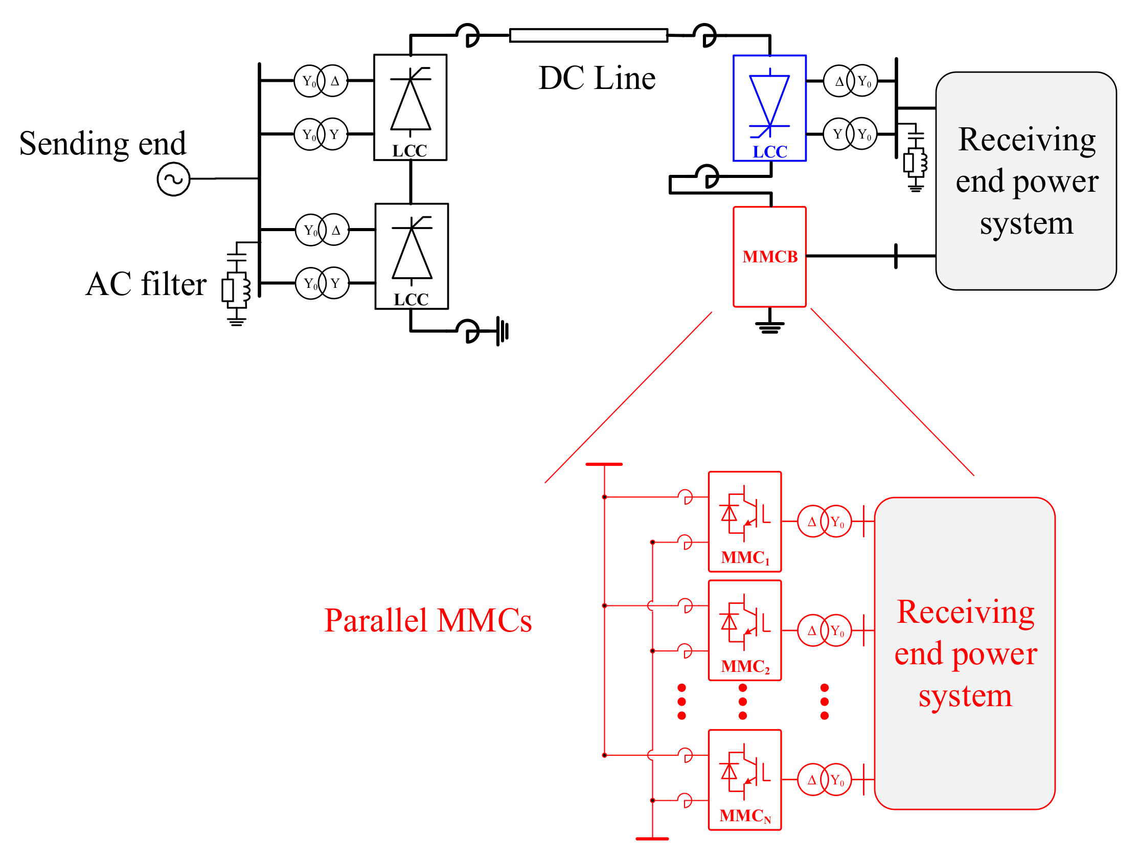
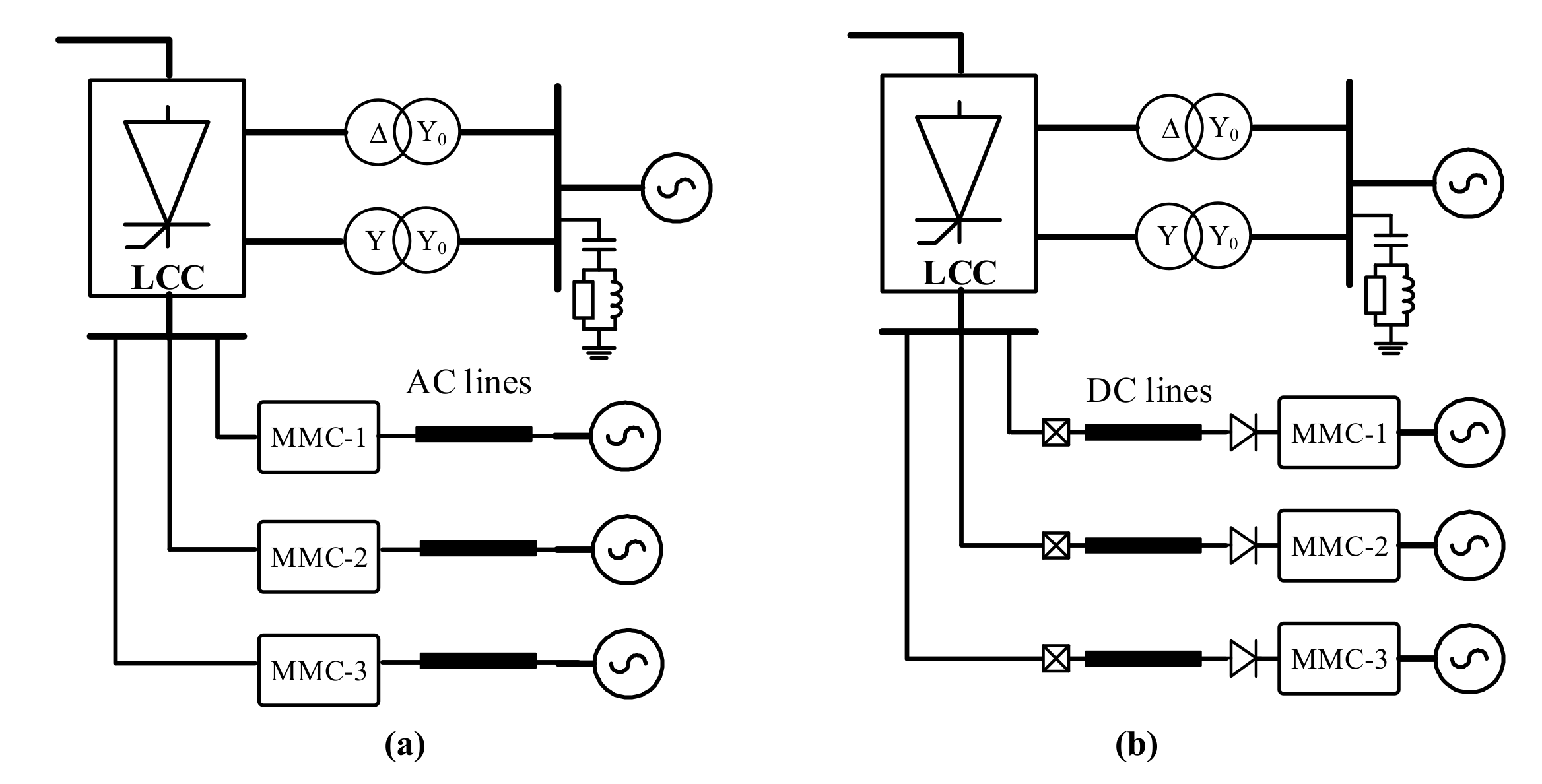
2. Topology of Decentralized Hybrid HVDC Systems

In a decentralized hybrid HVDC system, the rectifier station is usually composed of large capacity LCCs, without considering the decentralized connection mode. The topology of the decentralized hybrid HVDC system is shown in Figure 1. In Figure 1, the inverter station is composed of an LCC and an MMC bank (MMCB) in series, and the MMCB is composed of several MMCs in parallel. The receiving end LCC and each MMC can be connected to different AC buses. At present, an MMC’s capacity is usually smaller than that of an LCC. Therefore, multiple MMCs are needed to match the capacity of a receiving end LCC, which makes it possible for the inverter station to adopt a decentralized connection mode.
Usually, the inverter stations of LCC-MMC hybrid DC systems are composed of MMCs. When a DC short-circuit fault occurs, the receiving end power grid provides short-circuit current to the DC system through MMCs. In order to eliminate the DC fault, the inverter station needs to adopt full bridge module MMCs with active step-down capabilities. The topology in Figure 1 makes use of an LCC on the receiving end to give the HVDC system a DC fault cleaning ability. Because the current direction of LCCs is fixed, when a DC system short-circuit fault occurs, the receiving power grid will not provide a short-circuit current to the DC system. Therefore, the MMCB can adopt half-bridge sub-modules to reduce the cost. Compared with a traditional LCC-MMC hybrid HVDC system, the cost of the decentralized hybrid HVDC system is much lower. Compared with the traditional LCC HVDC system, the MMC of the decentralized hybrid HVDC system has no commutation failure problem, which is conducive to improving the stability of AC systems.

3. Electromechanical Transient Modeling of Decentralized Hybrid HVDC System

The topology of the decentralized hybrid HVDC system was introduced above, and the electromechanical transient modeling will be carried out in the following section. Firstly, the structure of the electromechanical transient model is presented. Then, the electromechanical transient models of the LCC, the MMC, and the converter interface are established. Among them, the LCC model and the MMC model have been proposed before; here, we restate previous research. The inverter interface model is proposed in this paper.

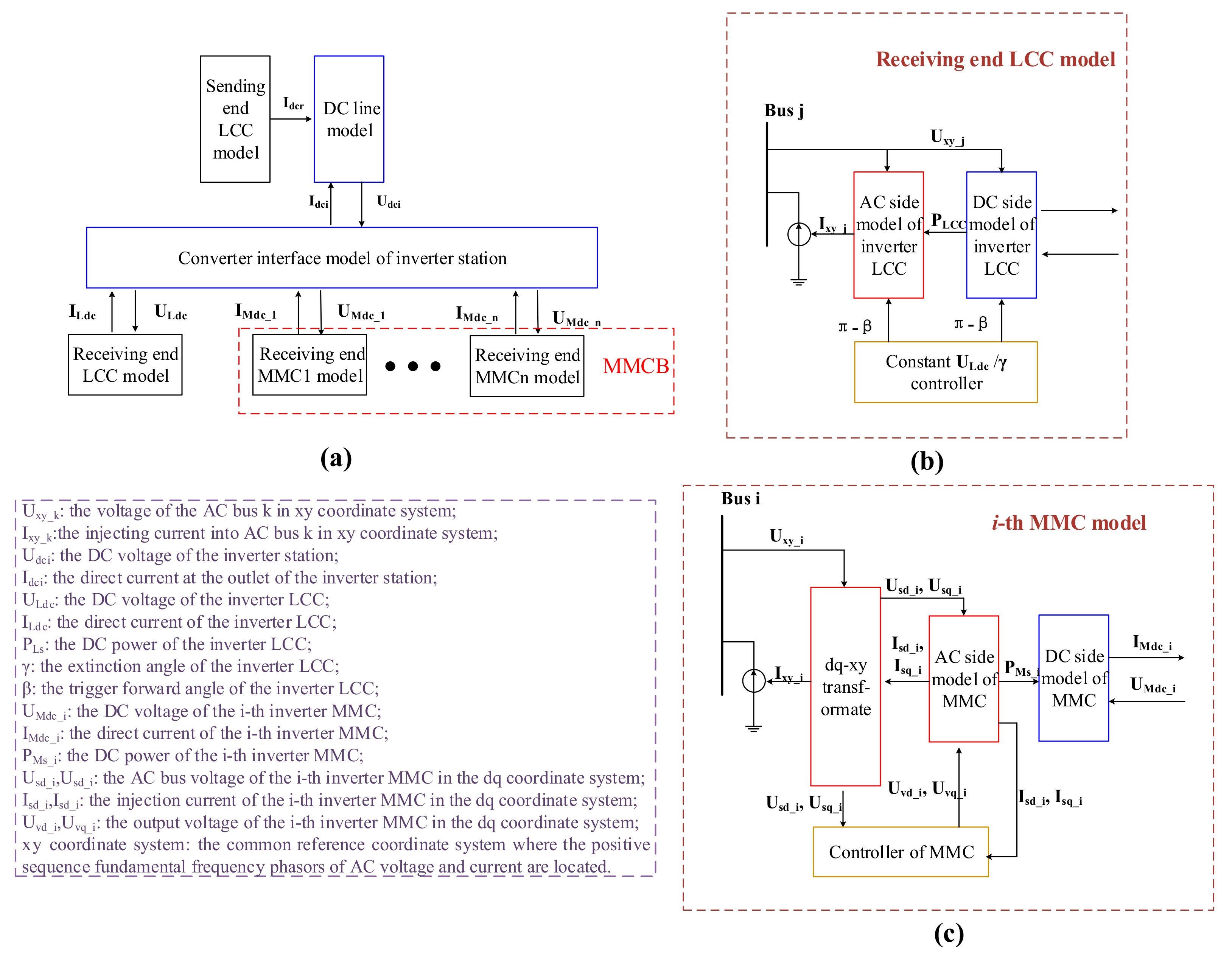
3.1. Structure of the Electromechanical Transient Model

The establishment of an electromechanical transient model requires the construction of differential-algebraic equations (DAEs) for this model. Overall, the electromechanical transient model of a decentralized hybrid HVDC system includes four modules:
(1)
The rectifier side LCC model, consisting of an AC side model and a DC side model.
(2)
The DC line model, with resistance, inductance, and capacitance.
(3)
The receiving end LCC/MMC model, consisting of an AC side model and a DC side model.
(4)
The interface model among the converters of the inverter station.
The whole structure of the decentralized hybrid HVDC system model is shown in Figure 2. The diagrammatic sketch of the HVDC system is shown in Figure 2a, which mainly illustrates the interaction variables between modules. The detailed structures of the receiving end LCC model. The DC line model, which can be found in [9], will not be shown in this paper. The detailed structures of the receiving end LCC and the MMC are shown in Figure 2b,c respectively.
In theory, the number of MMCs contained in the MMCB can be arbitrary. When the number of MMCs is determined, the DAEs of the decentralized hybrid HVDC system can be constructed by putting the DAEs of all modules together. Among all modules in Figure 2a, only the converter interface has not been studied, and there have been mature electromechanical transient models for other modules. Therefore, the following work mainly derives the inverter interface model. The DAEs of the receiving end LCC and MMC are needed to deduce the inverter interface model, which will be first given in the following.

3.2. Electromechanical Transient Modeling of Receiving End LCC

The receiving end LCC model consists of the DC side model and the AC side model. The equivalent circuit diagram of the receiving end LCC is shown in Figure 3 [25].
In Figure 3, PLs and QLs are the active and reactive power output of the receiving end LCC, ULdc is the DC voltage of the receiving end LCC, ILdc is the direct current of the receiving end LCC, μL is the commutation angle, β is the trigger forward angle, γ is the extinction angle, XtL is the leakage reactance, ULs is the AC bus voltage, k is the transformation ratio, NbL is the number of six-pulse bridges, and Ldc is the smoothing reactor inductor. The DAEs of the receiving end LCC are summarized as (1)–(5):
P L s = U L d c I L d c
μ L = β cos 1 cos β + 2 I L d c X tL k L / U Ls
γ = β μ L
Q L s = 3 N bL U Ls 2 4 π X tL k L 2 2 μ L + sin 2 γ sin 2 γ + 2 μ L
N bL L d c d I L d c d t = U L d c N bL 3 2 U Ls π k L cos β N bL 3 X tL π I Ldc .

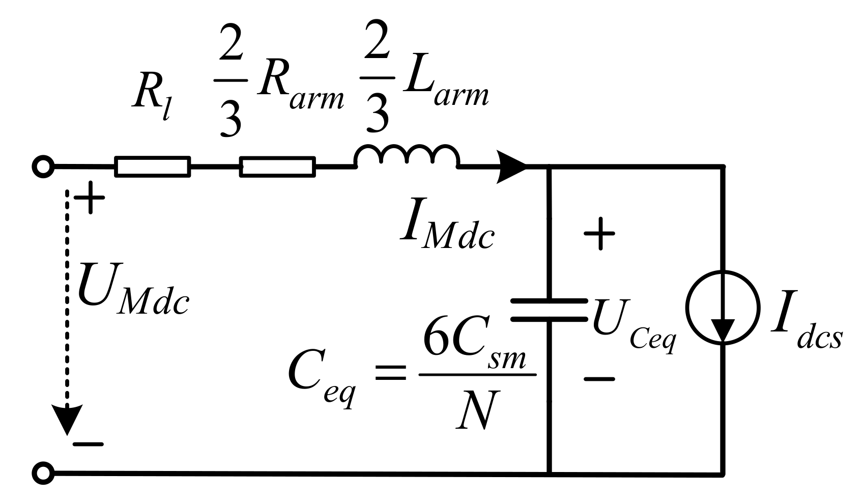
3.3. Electromechanical Transient Modeling of the MMC

The electromechanical transient model of the MMC can be divided into two parts, including the AC side model and the DC side model. There have been many related studies before. An MMC model considering the dynamic characteristic of the bridge arm inductance is proposed in [9], and this model is adopted in this paper.
(1) MMC AC Side Model
Generally, the three-phase time variables of the MMC are transformed into the variables in the mutually perpendicular dq coordinate system, and the MMC AC side model in the dq coordinate system is shown as (6).
d i s d d t = 1 L a c ( u s d U v d + ω L a c i s q R a c i s d ) d i s q d t = 1 L a c ( u s q U v q ω L a c i s d R a c i s q )
Here, isd and isq are the current injected into the AC bus in the dq coordinate system, Lac is the AC side equivalent inductance, Rac is the AC side equivalent resistance, usd and usq are the AC bus voltage in the dq coordinate system, Uvd and Uvq are the AC output voltage of the MMC in the dq coordinate system, and ω is the AC bus frequency.
(2) MMC DC Side Model
There are two access method for the inverter station of the decentralized hybrid HVDC system. One is the concentrated access and the other is the distributed access. The concentrated access means that the receiving end LCC and the MMCs are placed in one inverter station, and AC lines are used to connect the receiving end converters with different AC buses. The distributed access means that the receiving end LCC and the MMCs are placed in different inverter stations, and the DC lines are used to connect the LCC with the MMCs. The difference between the concentrated access and the distributed access is shown in Figure 4.
As can be seen from Figure 4, if the inverter station adopts the distributed access, DC lines need to be considered in the electromechanical transient model of the MMC. For the sake of generality, DC lines between the receiving end LCC and the MMCs are considered in this paper. Considering that the receiving end LCC and the MMCs are connected with the same receiving power grid, DC lines between them are usually short. Therefore, the DC lines are equivalent to resistance. The equivalent circuit diagram of the MMC DC side model considering the DC line is shown in Figure 5.
The MMC DC side model is usually equivalent to that of a capacitor and a current source in parallel. Here, the MMC DC side model considering the bridge arm inductance is adopted [9]. The corresponding DAEs are given in (7). In (7), RMMC is the equivalent resistance of the MMC, Rl is the resistance of the DC line, Rarm is the resistance of the bridge arm, Larm is the inductance of the bridge arm, IMdc is the direct current of the MMC, UMdc is the DC voltage of the MMC, Csm is the capacitance of the bridge arm sub-module, Ceq is the equivalent lumped capacitance of the MMC, UCeq is the voltage of the Ceq, Idcs is the current of the equivalent current source, and PMs is the active power output of the MMC:
2 3 L arm d d t I Mdc = U Mdc U Ceq R M M C I Mdc C eq d d t U Ceq = I Mdc I dcs I d c s = P M s U c e q R M M C = 2 3 R a r m + R l .

3.4. Interface Model among LCC and MMCs

For different converters in an inverter station, their AC side models are independent, whereas the DC side models are coupled in series and parallel. Therefore, an interface model is essential to decouple the converters.
The target of the interface model is to calculate the DC voltage of each converter and the outlet current of the inverter station. The DC side equivalent circuit of the inverter station is shown in Figure 6. In Figure 6, Idci is the direct current at the outlet of the inverter station, Udci is the DC voltage of the inverter station, ULdc is the DC voltage of the receiving end LCC, and UMdc is the DC voltage of the receiving end MMC.
Next, the interface model in Figure 6 is established. In Figure 6, the differential equation of the LCC is rewritten as (8) according to (5). The current differential equation of the kth MMC is (9):
N b L L d c d I d c i d t = U Ldc N b L 3 2 U L s π k L cos β N b L 3 X t L π I d c i
2 3 L arm - k d d t I dc - k = U Mdc U Ceq - k R MMC - k I dc - k
where Larm-k is the arm inductance of the kth MMC, Idc-k is the DC current of the kth MMC, Uceq-k is the equivalent lumped capacitance voltage of the kth MMC, and RMMC-k is the equivalent resistance of the kth MMC.
Assuming that there are n MMCs in the MMCB, we get (10)–(12):
d d t k = 1 n I dc - k = k = 1 n 3 2 L arm - k U Mdc   k = 1 n 3 U Ceq - k 2 L arm - k k = 1 n 3 R MMC - k I dc - k 2 L arm - k
d I d c i d t = d k = 1 n I dc - k d t
I d c i = k = 1 n I dc - k .
Because the LCC and the MMCB are in series, their DC voltage should satisfy (13):
U d c i = U L d c + U M d c
U M d c = U d c i + N b L d c k = 1 n 3 U Ceq - k 2 L arm - k + N b L d c k = 1 n 3 R MMC - k I dc - k 2 L arm - k N b 3 2 U Ls π k cos β N b 3 X tr π I dci 1 + N b L d c k = 1 n 3 2 L arm - k
U L d c = N b L d c k = 1 n 3 2 L arm - k U d c i N b L d c k = 1 n 3 U Ceq - k 2 L arm - k N b L d c k = 1 n 3 R MMC - k I dc - k 2 L arm - k + N b 3 2 U Ls π k cos β + N b 3 X tr π I dci 1 + N b L d c k = 1 n 3 2 L arm - k .
By solving (8), (10), (11), and (13), the DC voltage expression of the receiving end LCC and the MMCB can be obtained as (14) and (15). Equations (12), (14), and (15) form the interface model of the LCC-MMC cascaded inverter station in Figure 6.

4. The Control Strategy of a Decentralized Hybrid HVDC System

The advantage of the decentralized hybrid HVDC system is that the receiving power system can absorb large DC power safely. However, under some N-1/N-2 conditions, it is possible for the DC power dissipation to be limited by the appearance of some overloaded components. In this situation, the output power of the MMCs and the receiving end LCC can be redistributed to solve the DC power dissipation problem. In the following, an off-line parameter optimization strategy is proposed for envisaged N-1/N-2 conditions.
In a decentralized hybrid HVDC system, the modifiable variables including the direct current of the sending end LCC, the DC voltage of the receiving end LCC, the DC voltage of the MMC, and the current distribution among MMCs. By optimizing these variables, the active power of the LCCs and MMCs can be adjusted flexibly. Next, we give an optimal power flow (OPF) model, considering the decentralized hybrid HVDC system to optimize the parameters of the HVDC system.
In AC/DC systems, the OPF model can be simplified to a general non-linear optimization model, as shown in (16)–(18). This model can be solved by the interior point method:
o b j .    min .   f ( x )
s . t .    h ( x ) = 0
g ¯ g ( x ) g ¯ .
In this paper, the objective of the optimization is to minimize the loss of DC power. Therefore, the objective function of the OPF model can be written as (19):
min f = P D C 0 P L s k = 1 n P M s k
where PDC0 is the rated active power of the HVDC system under normal conditions, PLs is the output power of the receiving end LCC, and PMs-k is the output power of the kth receiving end MMC, assuming that there are n MMCs in an MMCB.
First, the inequality constraints of the decentralized hybrid HVDC system are introduced.
The active power provided by the sending end power grid should be limited to a normal range. This constraint is shown in (20):
0 < P r s < P r s , max
where Prs is the active power provided by the sending end power grid and Prs,max is the maximum active power, which can be provided by the sending end power grid. Prs,max is usually set to the rated power under normal conditions.
Due to the limitation of the sending end LCC’s overcurrent capability, the range of the direct current should be restricted. This constraint is shown in (21):
I d c , min < I d c < I d c , max
where Idc is the direct current of the sending end LCC, Idc,min is the minimum direct current limitation, and Idc,max is the maximum direct current limitation.
The trigger angle limitation of the sending end LCC is
α min < α < α max
where α is the trigger angle of the sending end LCC, αmin is the minimum trigger angle limitation, and αmax is the maximum trigger angle limitation.
The DC voltage limitation of the sending end LCC is
U d c r , min < U d c r < U d c r , max
where Udcr is the DC voltage of the sending end LCC, Udcr,min is the minimum DC voltage limitation of the sending end LCC, and Udcr,max is the maximum DC voltage limitation of the sending end LCC.
The extinction angle limitation of the receiving end LCC is
γ min < γ < γ max
where γ is the extinction angle of the receiving end LCC, γmin is the minimum extinction angle of the receiving end LCC, and γmax is the maximum extinction angle of the receiving end LCC.
The direct current limitation of the MMCs is
I d c k , min < I d c k < I d c k , max k = 1 , 2 , , n
where Idc-k is the direct current of the kth MMC, Idc-k,min is the minimum direct current limitation of the kth MMC, and Idc-k,max is the maximum direct current limitation of the kth MMC.
The DC voltage limitation of the MMCB is
U M d c , min < U M d c < U M d c , max
where UMdc is the DC voltage of the MMCB, UMdc,min is the minimum direct current limitation of the MMCB, and UMdc,max is the maximum direct current limitation of the MMCB.
The reactive power limitation of the MMCs is
Q M s k , min < Q M s k < Q M s k , max
where QMs-k is the reactive power of the kth MMC, QMs-k,min is the minimum reactive power limitation of the kth MMC, and QMs,max is the maximum reactive power limitation of the kth MMC.
Then, the equality constraints of the decentralized hybrid HVDC system are introduced.
The steady state equations of the sending end LCC and the DC line are
P r s = U d c r I d c Q r s = 3 N br U s r 2 4 π X tr k r 2 2 μ r + sin 2 α sin 2 α + 2 μ r
U d c r = U d c i + I d c R b r
α = cos 1 π k r 3 2 N b r U s r U d c r + 3 N b r X t r π I d c
where Udcr is the DC voltage of the sending end LCC, Rbr is the DC line resistance, kr is the transformation ratio of the sending end LCC, Nbr is the six-pulse bridges number of the sending end LCC, Usr is the AC bus voltage of the sending end LCC, Xtr is the leakage reactance of the sending end LCC, Qrs is the reactive power of the sending end LCC, and μr is the commutation angle of the sending end LCC.
The steady state equations of the receiving end LCC are
U L d c = N b L 3 2 U L s π k L cos β + 3 N b L X t L π I d c
γ = cos 1 cos β + 2 I L d c X t L k L / U L s
μ L = β γ
P L s = U L d c I d c Q L s = 3 N bL U Ls 2 4 π X tL k L 2 2 μ L + sin 2 γ sin 2 γ + 2 μ L
where NbL is the six-pulse bridges number of the receiving end LCC, ULs is the AC bus voltage of the receiving end LCC, kL is the transformation ratio of the receiving end LCC, XtL is the leakage reactance of the receiving end LCC, ILdc is the direct current of the receiving end LCC, μL is the commutation angle of the receiving end LCC, PLs is the active power of the receiving end LCC, QLs is the reactive power of the receiving end LCC.
The steady state equations of the MMCs are shown in (35) and (36):
U C e q k = U M d c 2 3 R a r m k I d c k
P M s k = U C e q k I d c k
where UCeq-k is the voltage of the equivalent lumped capacitance, RMMC-k is the equivalent resistance of the MMC, PMs-k is the active power of the kth MMC.
The steady state equations of the interface model are shown in (37) and (38):
I d c = k = 1 n I d c k
U d c i = U L d c + U M d c .
Equality constraints and inequality constraints of the AC system are shown in (39)–(42) [25]:
P G i P D i V i j = 1 n V j ( G i j cos θ i j + B i j sin θ i j ) = 0 Q G i Q D i V i j = 1 n V j ( G i j sin θ i j B i j cos θ i j ) = 0
Q R i ¯ Q R i Q R i ¯
V i ¯ V i V i ¯
P i j = V i V j G i j cos θ i j + B i j sin θ i j V i 2 G i j P i j ¯
where (39) is the bus power balance equation, (40) is the reactive power output constraint of reactive power source, (41) is the constraint of bus voltage, and (42) is the constraint of the branch power flow. In addition, if the q-axis of the MMC is controlled in the constant AC bus voltage mode, then the Point of Common Coupling (PCC) of the MMC can be regarded as a PV bus. If the q-axis of the MMC is controlled in the constant reactive power mode, then the PCC of the MMC can be regarded as a PQ bus. The reactive power output limitation of the MMCs is considered in (40).
The control variables in the OPF model include the direct current Idc, the DC voltage of the receiving end LCC ULdc, the DC voltage of the MMCs UMdc, and the direct current of the MMCs Idc-k (k = 1,2,…,n). The control variables can be modified by changing the reference values of the controllers. The OPF model proposed above can be solved by the interior point method.
It should be noted that this strategy is to make a response plan in advance for the N-1/N-2 contingencies in question. When an appropriate N-1/N-2 contingency occurs, the control variables of the decentralized hybrid HVDC system are modified according to the pre-calculated results.

5. Case Study

In this section, the electromechanical transient model and the control strategy proposed above are verified by simulation. We build the decentralized hybrid HVDC system in PSS/E and PSCAD/EMTDC, respectively. Firstly, the electromechanical transient model in PSS/E is verified by the electromagnetic transient model on PSCAD/EMTDC. Then, a modified New England 39-bus system is built in PSS/E and the control strategy is verified by simulation in the modified New England 39-bus system.

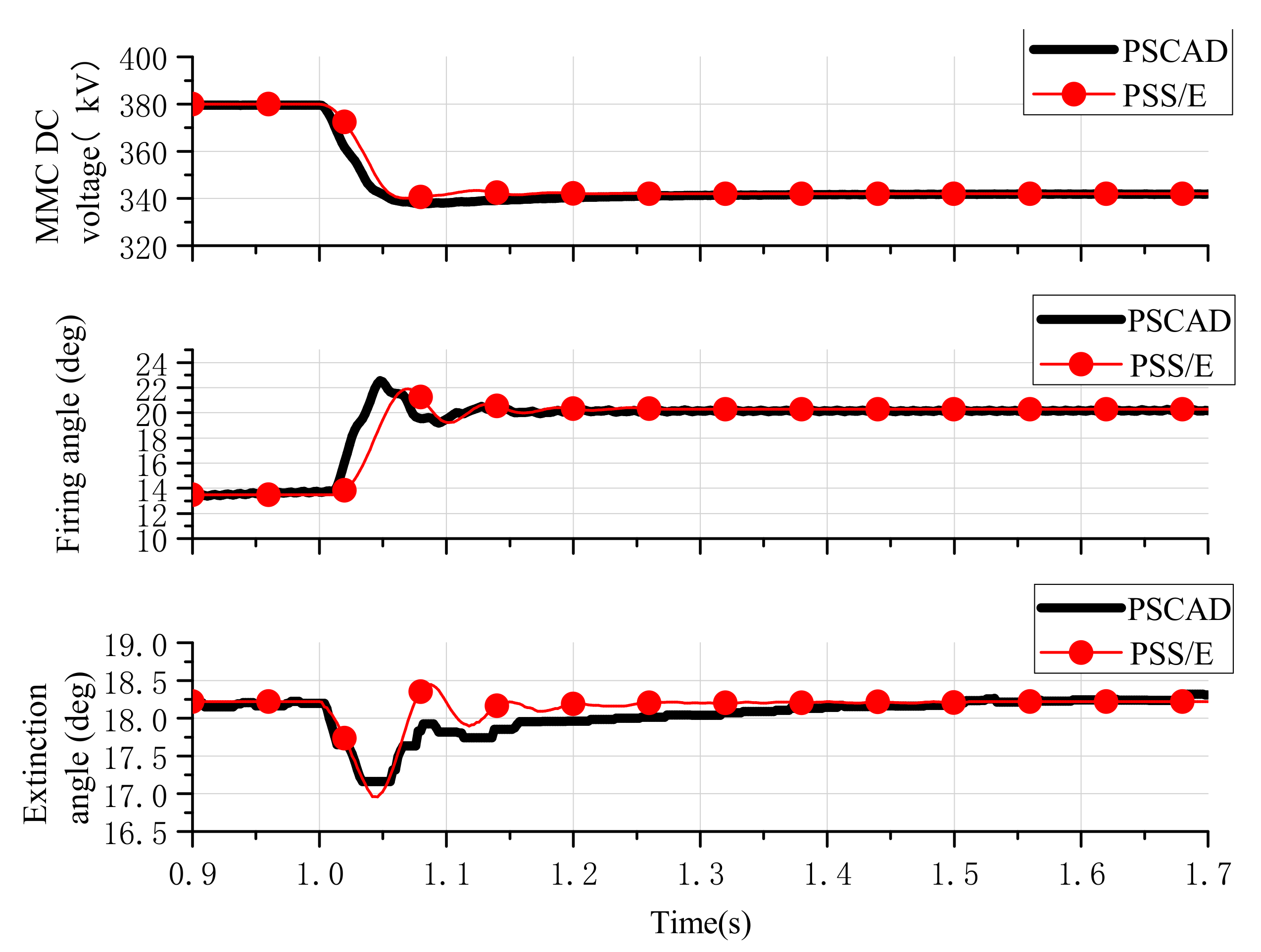
5.1. Validation of Electromechanical Transient Model of Dencentralzied Hybrid HVDC System

Firstly, the electromechanical transient model of the decentralized hybrid HVDC system is validated. We build a decentralized hybrid HVDC system in PSS/E and PSCAD/EMTDC, respectively. The MMCB is composed of three MMCs in parallel. The sending end LCC and the receiving end LCC. The three MMCs are connected to different aggregated AC systems. The topology and the system parameters are shown in Figure 7 and Table 1.
When t = 1.0 s, the DC voltage reference of the MMCB is changed from 340 kV to 380 tokV, the dynamic responses of the electromechanical transient model and the electromagnetic transient model are shown in Figure 8. As can be seen from Figure 8, the DC voltage reference change leads to an increase of the firing angle of the rectifier side LCC. The firing angle increases from 14.1° to 20.2°. The extinction angle of the receiving end LCC decreases first, then increases, and finally returns to the original steady-state value of 18.2°. From Figure 8, it can be seen that the dynamic responses of the electromechanical transient model in PSS/E and the electromagnetic transient model in PSCAD/EMTDC are basically the same. In order to quantitatively evaluate the similarities between the response curves of the electromechanical transient model and the electromagnetic transient model, the Feature Selective Validation (FSV) method is used [26,27]. In [26], an index global difference measure (GDM) is proposed, and the GDM is associated with a GRADE-SPREAD pair. By calculating the values of the GRADE and the SPREAD, the degree of similarity between two curves can be quantitatively evaluated. The variation of the GRADE and the SPREAD both range from 1 (best quality) to 6 (worst quality). Taking the MMC DC voltage curves in Figure 8 as an example, the GRADE and the SPREAD values are calculated to be 1 and 2, respectively. For the three variables in Figure 8, neither the GRADE nor the SPREAD exceed 2. Therefore, the accuracy of the electromechanical transient model is verified.
It is noteworthy that although the response difference between the electromechanical transient model and the electromagnetic transient model is small, the response characteristics of the two models are still different in the transient process. This is because the mathematical models used in the electromechanical transient simulation and electromagnetic transient simulation are different. The electromagnetic transient simulation process is based on three-phase instantaneous values. The model used in the electromagnetic transient simulation is very detailed, while the simulation calculation process is complex, and the simulation scale is limited. Electromechanical transient simulation usually uses a fundamental phasor for its calculation, which is more suitable for large-scale power system simulations and analyses. Because of the inherent differences between the electromechanical transient simulation and the electromagnetic transient simulation, the accuracy of the electromechanical transient model is not the same as that of the electromagnetic transient model. The electromechanical transient model proposed in this paper is close enough to the electromagnetic transient model in accuracy and can meet the requirements of electromechanical transient simulation.

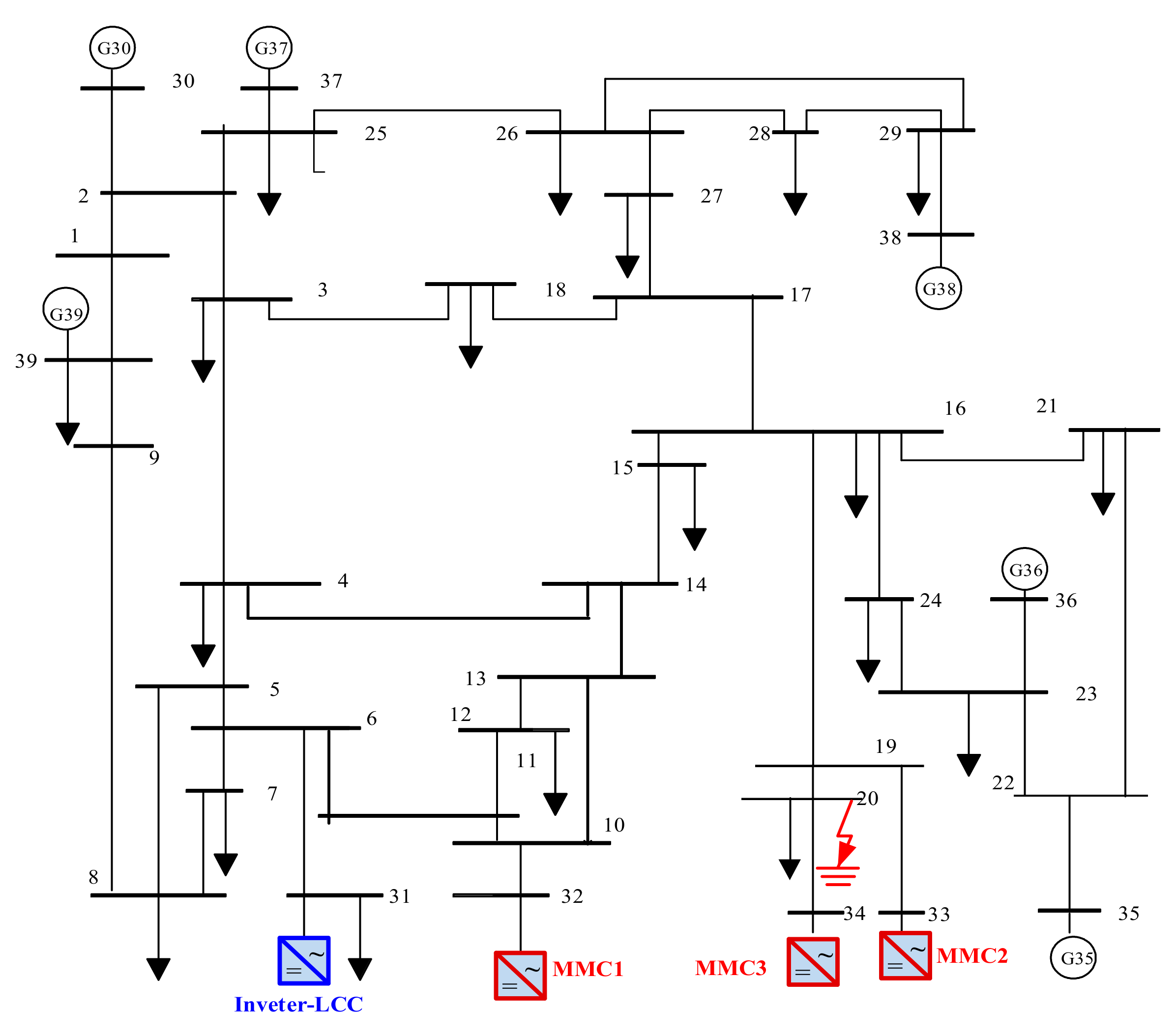
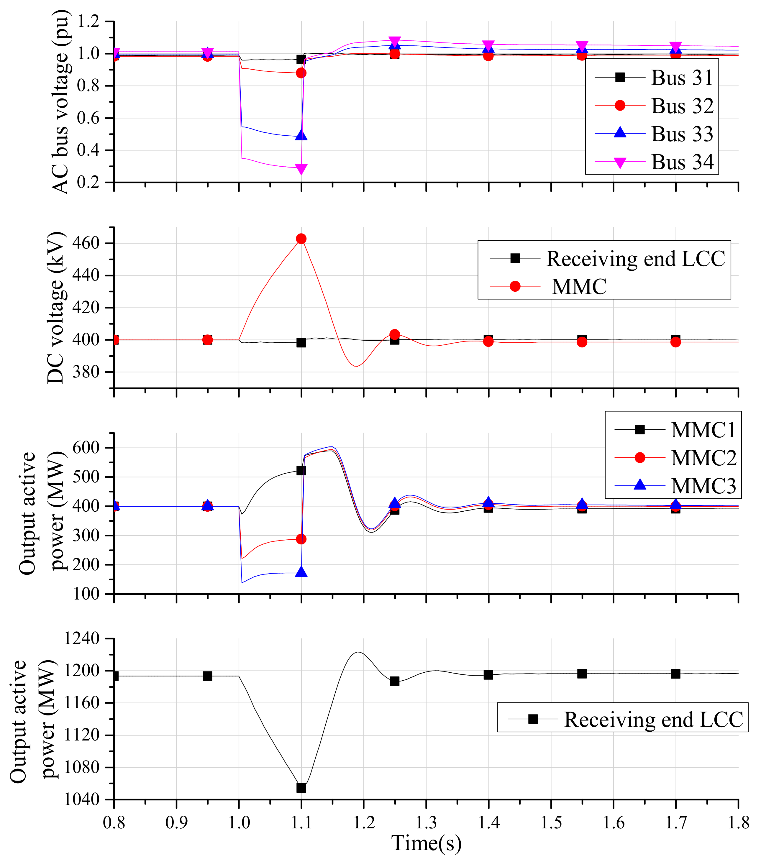
5.2. Dynamic Analysis of the 39-Bus System with a Decentralized Hybrid HVDC System

A modified New England 39-bus system embedded with the decentralized hybrid HVDC system is built on PSS/E. The topology of the decentralized hybrid HVDC system is the same as the system in Figure 7. The sending end LCC is connected to an aggregated AC system, and the inverter station is connected to the modified New England 39-bus system. The parameters of the HVDC system are given in Table 2, and the MMCs share the same parameters.
The structure of the receiving AC system is shown in Figure 9. The receiving end LCC is connected to bus 31, and the three MMCs are connected to buses 32 to 34. In the 39-bus system, the LCC and the MMCs replace the original four generators, and some compensation capacitors are added to keep the bus voltage in a normal range.
Next, we will carry out the simulation. Assuming that the branch connecting the bus 20 and the bus 34 has a three-phase short-circuit fault at 1.0 s, and the fault is cleared at 1.1 s. The dynamic response of the HVDC system is shown in Figure 10.
As can be seen from Figure 10, due to the large AC bus voltage drop of the bus 33 and bus 34, the output active power of the MMC2 and the MMC3 decreases sharply. The voltage drop of the bus 32 is small, and much active power can still be delivered through the MMC1. As a result, part of the active power is transferred from the MMC2 and the MMC3 to the MMC1. This feature enables the decentralized hybrid HVDC system to transmit more power during the AC bus short circuit fault, which is conducive to reducing the power loss of the receiving power grid.
Although part of the power delivered by the MMC2 and the MMC3 is borne by the MMC1, the total transmission power of the three MMCs decreases, which increases the DC voltage of the MMCB. However, the DC voltage variation of the receiving end LCC is very small, which indicates that the DC voltage coupling degree between the LCC and the MMC is low. This conclusion can also be verified by analyzing the influencing factors of the interface models (14) and (15).
In addition, the output power of the receiving end LCC decreases considerably, which will further increase the power gap of the receiving power grid. The reason for this phenomenon is that the increase of the inverter station DC voltage leads to a decrease of the direct current.

5.3. Simulation Verification of Control Strategy

The control strategy proposed in Section 4 will be verified in this section. The simulation system has been introduced in Section 5.2. In the following section, the N-1 condition after disconnecting the bus 5-bus 6 branch is selected to verify the control strategy. After disconnecting the bus 5-bus 6 branch, three branches of the 39-bus system face an overload risk. Then, DC power reduction and load shedding can occur without taking measures. The overload situation is shown in Table 3.
In order to eliminate the risk of overload, the branch load rate is usually reduced to less than 90%. Next, the OPF model proposed in Section 4 is used to optimize parameters of the decentralized hybrid HVDC system. Using the interior point method, the optimization results are obtained as shown in Table 4.
After adjusting the parameters of the HVDC system according to Table 4, the load conditions of the target branches can be obtained, as shown in Table 5. There are no new overloaded components after adjusting optimization.
Comparing the results before and after optimization, it can be seen that the optimization strategy can effectively guarantee the normal absorption of DC power under N-1/N-2 conditions. However, it should be noted that the reactive power absorbed by the LCCs increases due to the change of DC voltage and direct current. In this case, the reactive power absorbed by the sending end LCC and the receiving end LCC increases by 41.2% and 28.7%, respectively. Therefore, the control strategy proposed in this paper requires the converter station to have a certain reactive power compensation reserve capacity. This will increase the corresponding investment. However, the usual way to solve the overload problem is to build more transmission channels. Compared with the transmission channels, the cost of the compensating capacitors is lower. Therefore, the control strategy proposed in this paper has practical value.

6. Conclusions

In this paper, the electromechanical transient model of the decentralized hybrid HVDC system is proposed. This model simplifies the HVDC system to a certain extent and is a trade-off between computational efficiency and accuracy. By comparing this system with the electromagnetic transient model, it can be concluded that the electromechanical transient model proposed in this paper can meet the accuracy requirements of electromechanical transient simulations. In addition, the interface model proposed in this paper is composed of algebraic equations, which can be easily implemented in electromechanical transient simulation software. Therefore, the model proposed in this paper is suitable for AC/DC large-scale system simulations.
An optimal power flow model considering a decentralized hybrid HVDC system is put forward. The function of this model is to optimize the power allocation among converters under N-1/N-2 conditions, to ensure that the AC system can absorb DC power safely. However, after adjusting the active power of the LCCs, the reactive power absorbed by the LCCs will probably increase. Therefore, this strategy requires LCCs to be equipped with more compensation capacitors. This strategy is a trade-off between investment cost and security. The result obtained in a modified New England 39-bus system shows that this optimization strategy is effective.

Author Contributions

Conceptualization, G.W. and Z.X.; methodology, H.X.; software, G.W.; validation, L.X. and Z.Z.; formal analysis, H.X.; investigation, Z.X.; resources, Z.X.; data curation, Z.Z.; writing—original draft preparation, G.W.; writing—review and editing, H.X.; visualization, L.X.; supervision, Z.X.; project administration, Z.X.

Funding

This research received no external funding.

Conflicts of Interest

The authors declare no conflicts of interest

References

  1. Sun, Y.; Zhou, Q.; Shen, H. Analysis and Prospect on Development Patterns of China’s Power Transmission Network in Future. Power Syst. Technol. 2013, 37, 1929–1935. (In Chinese) [Google Scholar]
  2. Wang, C.; Zhu, L.; Chen, B.; Tang, Y.; Dai, Y. Analysis on voltage stability of hybrid system with UHVDC hierarchical connection to AC grid. In Proceedings of the 8th International Power Electronics and Motion Control Conference (IPEMC-ECCE Asia), Hefei, China, 22–25 May 2016; pp. 690–695. [Google Scholar]
  3. Lu, S.; Xu, Z.; Xiao, L.; Jiang, W.; Bie, X. Evaluation and Enhancement of Control Strategies for VSC Stations Under Weak Grid Strengths. IEEE Trans. Power Syst. 2018, 33, 1836–1847. [Google Scholar] [CrossRef]
  4. Li, S.; Wu, Z.; Huang, J. Power flow modelling to UHVDC line and its hierarchical connection mode. IET Gener. Transm. Distrib. 2018, 12, 1554–1564. [Google Scholar] [CrossRef]
  5. Liu, Z.; Qin, X.; Zhao, L.; Zhao, Q. Study on the Application of UHVDC Hierarchical Connection Mode to Multi-infeed HVDC System. Proc. CSEE 2013, 33, 1–7. (In Chinese) [Google Scholar]
  6. Li, G.; Zhang, S.; Jiang, T.; Chen, H. A method of detecting commutation failure in multi-infeed HVDC systems based on critical failure impedance boundary. In Proceedings of the IEEE Power & Energy Society General Meeting (PES-2017), Chicago, IL USA, 16–20 July 2017; pp. 1–5. [Google Scholar]
  7. Torres-Olguin, R.E.; Molinas, M.; Undeland, T. Offshore Wind Farm Grid Integration by VSC Technology With LCC-Based HVDC Transmission. IEEE Trans. Sustain. Energy 2012, 3, 899–907. [Google Scholar] [CrossRef]
  8. Zhang, Z.; Xu, Z.; Xue, Y.; Tang, G. DC-Side Harmonic Currents Calculation and DC-Loop Resonance Analysis for an LCC–MMC Hybrid HVDC Transmission System. IEEE Trans. Power Deliv. 2015, 30, 642–651. [Google Scholar] [CrossRef]
  9. Xiao, L.; Li, Y.; Xiao, H.; Zhang, Z.; Xu, Z. Electromechanical Transient Modeling of Line Commutated Converter-Modular Multilevel Converter-Based Hybrid Multi-Terminal High Voltage Direct Current Transmission Systems. Energies 2018, 11, 2102. [Google Scholar] [CrossRef]
  10. Zi, P.; Zhao, Z.; Chen, X.; Zhou, X.; Wan, L.; Shi, H.; An, N.; Tian, F. Electromechanical transient modeling of hybrid DC grid based on LCC and VSC converter. Proc. CSEE 2015, 24, 6265–6274. (In Chinese) [Google Scholar]
  11. Hahn, C.; Geuß, A.; Luther, M. Modeling and control design of hybrid—LCC and VSC based—HVDC systems. In Proceedings of the IEEE/PES Transmission and Distribution Conference and Exposition (T&D), Dallas, TX, USA, 2–5 May 2016; pp. 1–6. [Google Scholar]
  12. Jung, J.; Cui, S.; Lee, J.; Sul, S.K. A New Topology of Multilevel VSC Converter for a Hybrid HVDC Transmission System. IEEE Trans. Power Electron. 2017, 32, 4199–4209. [Google Scholar] [CrossRef]
  13. Tang, G.; Xu, Z. A LCC and MMC hybrid HVDC topology with DC line fault clearance capability. Int. J. Electr. Power Energy Syst. 2014, 62, 419–428. [Google Scholar] [CrossRef]
  14. Xiao, L.; Xu, Z.; Xiao, H.; Zhang, Z.; Wang, G.; Xu, Y. Electro-mechanical transient modeling of MMC based multi-terminal HVDC system with DC faults considered. Int. J. Electr. Power Energy Syst. 2019, 113, 1002–1013. [Google Scholar] [CrossRef]
  15. Chang, Y.; Cai, X. Hybrid Topology of a Diode-Rectifier-based HVDC System for Offshore Wind Farms. IEEE J. Emerg. Sel. Top. Power Electron. 2018, 1. [Google Scholar] [CrossRef]
  16. Xu, Z.; Wang, S.; Xiao, H. Hybrid high-voltage direct current topology with line commutated converter and modular multilevel converter in series connection suitable for bulk power overhead line transmission. IET Power Electron. 2016, 9, 2307–2317. [Google Scholar] [CrossRef]
  17. Guo, C.; Liu, W.; Zhao, C.; Ni, X. Small-signal dynamics and control parameters optimization of hybrid multi-infeed HVDC system. Electr. Power Energy Syst. 2018, 98, 409–418. [Google Scholar] [CrossRef]
  18. Lebre, J.R.; Watanabe, E.H. Fullbridge MMC control for hybrid HVDC systems. In Proceedings of the Brazilian Power Electronics Conference (COBEP), Juiz de Fora, Brazil, 19–22 November 2017; pp. 1–6. [Google Scholar]
  19. Cai, Y.; Wen, M.; Chen, Y.; Shi, Y.; Qin, Y. Low DC voltage control strategy of bipolar LCC-MMC hybrid HVDC transmission system. In Proceedings of the 2nd International Conference on Power and Renewable Energy (ICPRE), Chengdu, China, 20–23 September 2017; pp. 166–171. [Google Scholar]
  20. Lee, Y.; Cui, S.; Kim, S.; Sul, S.-K. Control of hybrid HVDC transmission system with LCC and FB-MMC. In Proceedings of the IEEE Energy Conversion Congress and Exposition (ECCE), Pittsburgh, PA, USA, 14–18 September 2014; pp. 475–482. [Google Scholar]
  21. Xue, Y.; Ge, F.; Zhao, Z.; Zhang, Z.; Xing, F. Control strategy for hybrid LCC-C-MMC HVDC system under AC fault at rectifier side. IET J. Eng. 2019, 16, 3259–3263. [Google Scholar] [CrossRef]
  22. Naushath, M.H.; Rajapakse, A.D.; Gole, A.M.; Fernando, I.T. Energization and regulation of a hybrid HVDC grid with LCC and VSC. In Proceedings of the IEEE Electrical Power and Energy Conference (EPEC), Saskatoon, SK, USA, 22–25 October 2017; pp. 1–6. [Google Scholar]
  23. Yu, Y.; Lu, Y.; Chen, Q. Internal model startup control for VSC-LCC based hybrid pseudo bipolar HVDC system. In Proceedings of the 2nd International Conference on Power and Renewable Energy (ICPRE), Chengdu, China, 20–23 September 2017; pp. 15–19. [Google Scholar]
  24. Sun, S.; Xiang, W.; Yao, L.; Li, Y.; Wen, J. Control and operation of a hybrid HVDC integrating wind farm based on SB-MMC and LCC. IET J. Eng. 2017, 2017, 816–821. [Google Scholar] [CrossRef]
  25. Prabna, K. Power System Stability and Control; McGraw-Hill: New York, NY, USA, 1994; ISBN 007035958X. [Google Scholar]
  26. Duffy, A.P.; Martin, A.J.M.; Orlandi, A.; Antonini, G.; Benson, T.M.; Woolfson, M.S. Feature selective validation (FSV) for validation of computational electromagnetics (CEM). part I—The FSV method. IEEE Trans. Electromagn. Compat. 2006, 48, 449–459. [Google Scholar] [CrossRef]
  27. Orlandi, A.; Duffy, A.P.; Archambeault, B.; Antonini, G.; Coleby, D.E.; Connor, S. Feature selective validation (FSV) for validation of computational electromagnetics (CEM). part II—Assessment of FSV performance. IEEE Trans. Electromagn. Compat. 2006, 48, 460–467. [Google Scholar] [CrossRef]
Figure 1. Unipolar topology of decentralized hybrid systems with a line commutated converter (LCC) rectifier and line commutated converter-modular multilevel converter (LCC-MMC) cascaded inverter.
Energies 12 02856 g001
Figure 2. The whole structure of the electromechanical model of the decentralized hybrid High Voltage Direct Current (HVDC) system. (a) The diagrammatic sketch of the whole system. (b) The detailed structure of the receiving end LCC. (c) The detailed structure of the MMC.
Energies 12 02856 g002
Figure 3. Equivalent circuit diagram of the LCC. (a) A 12-pulse converter. (b) The AC side equivalent circuit diagram. (c) The DC side equivalent circuit diagram.
Energies 12 02856 g003
Figure 4. The difference between the concentrated access and the distributed access. (a) The diagrammatic sketch of the concentrated access. (b) The diagrammatic sketch of the distributed access.
Energies 12 02856 g004
Figure 5. Equivalent circuit diagram of MMC DC side model.
Energies 12 02856 g005
Figure 6. The DC side equivalent circuit diagrams of the decentralized inverter station.
Energies 12 02856 g006
Figure 7. Unipolar topology of the decentralized hybrid system with three modular multilevel converters (MMCs).
Energies 12 02856 g007
Figure 8. Dynamic response comparison between electromechanical model and electromagnetic model.
Energies 12 02856 g008
Figure 9. Modified New England 39-bus system.
Energies 12 02856 g009
Figure 10. Dynamic response of the HVDC system after an AC short circuit fault occurs.
Energies 12 02856 g010
Table 1. Parameters of the Decentralized Hybrid HVDC System with Three MMCs.
ItemRectifierInverter High Voltage EndInverter Low Voltage End
Converter typeLCCLCCThree MMCs in parallel
Rated L-L RMS voltage of AC system (kV)525525525
Rated capacity of converter(MVA)50002500800 × 3
Rated DC voltage (kV)800400400
Smoothing reactor (mH)150150150
Capacitance of sub module (μF)//6941
Number of sub module per arm//100
Control modeConstant direct currentConstant DC voltageConstant DC voltage/reactive power
Reference 6.27 kA382 kV382 kV/0 Mvar
Table 2. The parameters of a decentralized hybrid HVDC system in a 39-bus system.
ItemRectifier LCCInverter LCCMMC
Active power output (MW)−2450.41200.0398.8
Reactive power output (Mvar)−1024.86−514.910.0
Control modeConstant direct currentConstant DC voltageConstant DC voltage/reactive power
Reference3 kA400.0 kV400.0 kV/0 Mvar
Table 3. Statistical Table of Overloaded Components Under an N-1 Contingency.
BranchLoad Power (MVA)Long Term Allowable Load Power (MVA)Load Rate (%)
Bus 6–Bus 7977.1900108.6
Bus 10–Bus 13577.160096.2
Bus 13–Bus 14610.6600101.8
Table 4. Optimization Results.
Converter TypeDirect Current (kA)DC Voltage (kV)Output Active Power (MW)Output Reactive Power (Mvar)
Sending end LCC3.67667.682450.4−1445.05
Receiving end LCC3.67228.71839.37−664.21
MMC10.87419.24364.0612.11
MMC21.40419.24592.795.23
MMC31.40419.24592.790.58
Table 5. Load Conditions of Target Branches After optimization.
BranchLoad Power (MVA)Load Rate
Bus 6–Bus 7809.089.9%
Bus 10–Bus 13376.962.8%
Bus 13–Bus 14393.965.6%

