Article

Thermal Transmittance of Internal Partition and External Facade LSF Walls: A Parametric Study

ISISE, Department of Civil Engineering, University of Coimbra, Pólo II, Rua Luís Reis Santos, 3030-788 Coimbra, Portugal
*
Author to whom correspondence should be addressed.
Energies 2019, 12(14), 2671; https://doi.org/10.3390/en12142671
Submission received: 22 June 2019 / Revised: 5 July 2019 / Accepted: 10 July 2019 / Published: 11 July 2019

Abstract

:
Light steel framed (LSF) construction is becoming widespread as a quick, clean and flexible construction system. However, these LSF elements need to be well designed and protected against undesired thermal bridges caused by the steel high thermal conductivity. To reduce energy consumption in buildings it is necessary to understand how heat transfer happens in all kinds of walls and their configurations, and to adequately reduce the heat loss through them by decreasing its thermal transmittance ( U -value). In this work, numerical simulations are performed to assess different setups for two kinds of LSF walls: an interior partition wall and an exterior facade wall. Several parameters were evaluated separately to measure their influence on the wall U -value, and the addition of other elements was tested (e.g., thermal break strips) with the aim of achieving better thermal performances. The simulation modeling of a LSF interior partition with thermal break strips indicated a 24% U -value reduction in comparison with the reference case of using the LSF alone ( U = 0.449 W/(m2.K)). However, when the clearance between the steel studs was simulated with only 300 mm there was a 29% increase, due to the increase of steel material within the wall structure. For exterior facade walls ( U = 0.276 W/(m2.K)), the model with 80 mm of expanded polystyrene (EPS) in the exterior thermal insulation composite system (ETICS) reduced the thermal transmittance by 19%. Moreover, when the EPS was removed the U -value increased by 79%.

1. Introduction

Buildings account for around 40% of the total energy consumption and about 36% of CO2 emissions in Europe [1]. The main factors of building energy consumption are the properties and design of the building envelope, the operation of building services, the occupants’ behavior and the climate/location [2,3,4,5]. Most of this energy, ranging from nearly 50% [6] up to 60% [7] depending on climate, design, use type and occupational patterns, is used by air-conditioning systems to achieve thermal comfort inside the buildings. Energy in the form of heat is dissipated to the environment at different rates according to the ventilation and building elements’ characteristics (e.g., thermal transmittance U -value). The rate of these losses/gains is important because it directly affects the operation and maintenance costs of mechanically ventilated and/or air conditioned buildings [8].
Usually a wall element is composed of several layers, such as internal and external cladding (e.g., cement mortar), one or two supporting panes (e.g., ceramic brick masonry), air cavity, and thermal and acoustic insulation (e.g., expanded polystyrene (EPS) or mineral wool). Typically lightweight steel framed (LSF) walls are made of the following main types of materials [9]: (1) supporting steel frame, which is constituted of cold formed profiles; (2) sheathing panels, such as inner gypsum plasterboard and outer oriented strand board (OSB), and; (3) insulation materials, such as mineral wool filling the air cavity between steel studs (which besides thermal insulation, has also an important acoustic insulation role [10]) and the exterior thermal insulation composite system (ETICS), where the thermal insulation material could be EPS (expanded polystyrene), XPS (extruded polystyrene), mineral wool or other.
The U -value of an opaque building element (e.g., facade LSF wall) depends on several factors, such as the thickness of each layer, the number of layers, the thermal conductivity of each layer material, the existence of thermal bridges due to the presence of an inhomogeneous thermal layer (e.g., a steel stud), the existence of air voids in the insulation, and the external and internal surface thermal resistances [11]. Perhaps the most relevant parameters regarding the thermal transmittance of a LSF building element are the level of insulation (i.e., its thickness), material properties (e.g., thermal conductivity) and positioning of insulation, and the amount of steel frame material [7,12].
In colder climates to reduce the U -value, and consequently the heat transmission losses, the level of thermal insulation is increased to diminish the heating energy demand [13]. While in warmer climates this level of thermal insulation could be reduced, reducing energy consumption for space heating/cooling as well as the embodied energy related with the insulation materials [14]. In these warmer climates the outdoor temperatures are often higher than the indoor temperatures, which could significantly increase the heat gains. Thus, the use of passive cooling strategies, such as natural ventilation [15], phase change materials [16], free cooling [17] and ground ventilation using an earth-to-air heat exchanger [18] becomes more relevant. In order to predict the energy consumption it is usual to perform advanced dynamic simulations of the entire building [19,20] or make use of more simplified approaches [21].
Apart from the level of thermal insulation (i.e., the thickness of thermal insulation layer(s)), in LSF elements, the position in the building element influences the effectiveness of this insulation (i.e., its U -value or thermal transmittance), and is thus very relevant [12]. Notice, that the thermal insulation positioning is also relevant to the effective thermal inertia/mass of the building, but this was not evaluated in the present paper, neither in reference [12] work. Moreover, this insulation, mainly the LSF batt insulation (e.g., mineral wool), is relevant not only for thermal purposes but also for acoustic insulation [10]. A typical interior partition and exterior facade LSF wall cross-sections will be studied in this paper, as presented later in Section 2.1 and Section 3.1, respectively.
At the design stage there are several ways to compute the U -value of a building element [11]. The detailed calculation method based on numerical simulations (e.g., finite element method (FEM)) should be performed using the modeling rules prescribed in standard ISO 10211 [22]. The most simple approach, applicable for homogeneous thermal layers, which may contain air layers up to 300 mm thick, is to consider the thermal resistance of each layer (depending on the thickness of the layer and on the thermal conductivity of the material) and to compute the reciprocal of the sum of all these thermal resistances, including both internal and external surface resistances [23]. Notice that the external thermal surface resistance mainly depends on the wind direction and velocity, as well as on the surface roughness [24].
The standard ISO 6946 [11] also prescribes an approximate method, known as the ‘Combined Method’, for building elements containing homogenous and inhomogeneous layers, including the effect of metal fasteners, by means of a U -value correction term. However, this methodology is not applicable for LSF elements, where the thermal insulation is bridged by metal (cold and hybrid frame construction), making this type of construction even more challenging in order to obtain an accurate and reliable U -value [23].
Several researchers devoted their attention to the thermal behavior and energy efficiency of LSF construction [5,9,23,25,26]. Soares et al. [26] performed a scientific bibliographic review about this kind of research. The first main driving research topic identified in the previous cited work was: “the development of single and combined strategies to reduce thermal bridges and to improve the thermal resistance of LSF envelope elements”. The present work deals with this suggested main research issue. Recently Santos et al. [23] accomplished a comparison between experimental measurements in LSF walls’ thermal transmittance and numerical simulations (2D and 3D FEM models) and analytical approach (ISO 6946 combined method). It was concluded that for the LSF wall with a simpler frame (i.e., only vertical steel studs) the analytical ISO 6946 and the 2D FEM numerical approaches provide quite good accuracy in the U -value estimation.
Since the ISO 6946 combined method is not applicable for LSF elements where the thermal insulation is bridged by the steel frames, some researchers developed some alternative analytical methods for this type of structure, such as Gorgolewsky [27] who developed a simplified analytical method for calculating U -values in LSF cold and hybrid construction. This method was based on the principles provided by ISO 6946, but adapted to consider the increased thermal effect of the steel frame, increasing the accuracy of the proposed methodology.
Given the high level of heterogeneity regarding the thermal conductivities of the materials composing the LSF elements, namely the steel frame and the thermal insulation, it is very challenging not only to accurately compute its thermal transmittance, but also to perform accurate and reliable measurements, both in-situ and in laboratory [8]. Regarding the experimental approach there are several methods for the thermal characterization of building elements, such as the heat flow meter (HFM) method, the guarded hot plate (GHP) method, the hot box (HB) method (which could be calibrated (CHB) or guarded (GHB)) and the infrared thermography (IRT) method. For LSF elements the most suitable experimental method, given its large heterogeneity in its component materials’ thermal conductivity (e.g., steel and thermal insulation), is the hot box apparatus, since the measurements are not local, but instead in a representative wall area [28].
Recently, Atsonios et al. [29] developed two experimental methods for in-situ measurement of the overall thermal transmittance of cold frame LSF walls, namely the representative points method (RPM) and weighted area method (WAM). These methods make use of the analysis of the examined wall using thermal IR images with the recording and processing of indoor/outdoor air temperature and heat flux. 
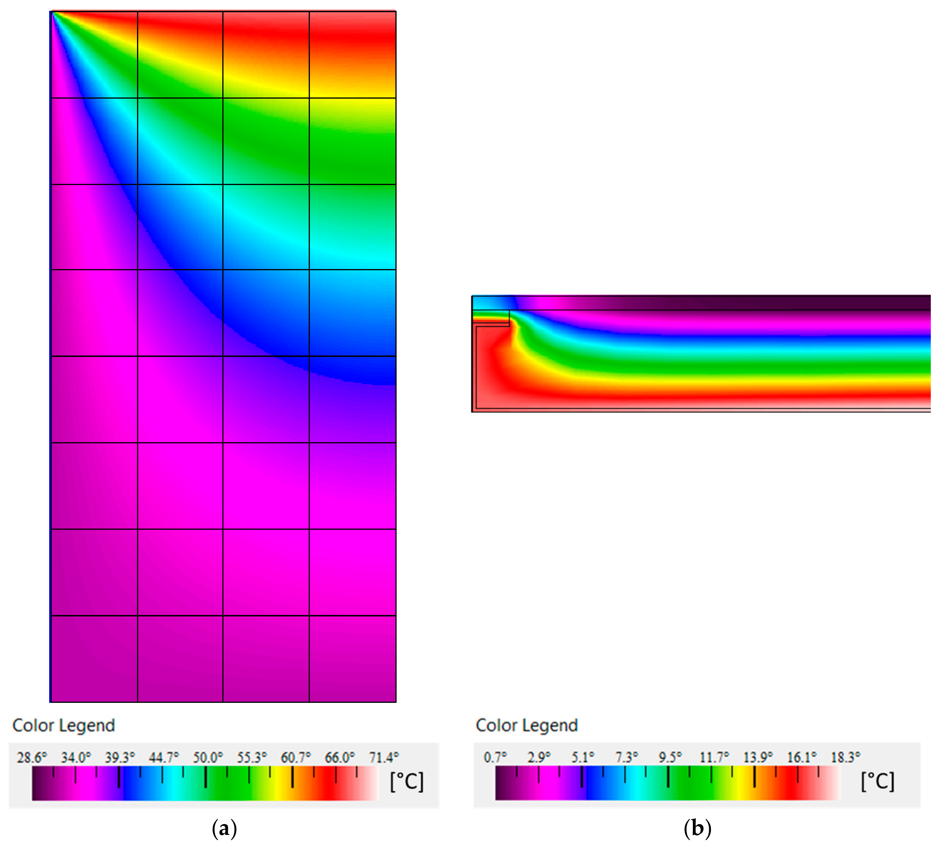
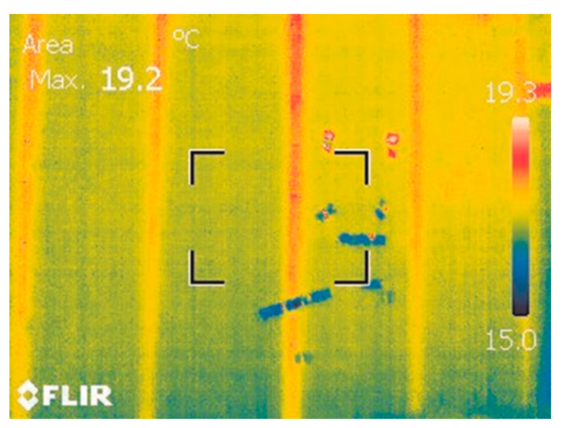
Figure 1 displays an infrared thermal image of an LSF wall, where the thermal bridge’s effect due to the high thermal conductivity of the vertical steel studs is quite visible. The vertical red lines denote higher surface temperatures due to an increased heat flow in the vicinity of each vertical steel profile, clearly identifying the position of them in the exterior colder surface of the LSF wall.
In fact, due to high thermal conductivity of steel in LSF structures, thermal bridges inspired many researchers to investigate the related thermal performance issues. De Angelis and Serra [31] evaluated the thermal insulation performance of metal framed lightweight walls and concluded that the correct evaluation of LSF walls’ thermal performance requires more complex and detailed analysis than the ones necessary for traditional reinforced concrete and masonry constructions.
Also in 2014, Santos et al. [30] evaluated the importance of flanking thermal losses of LSF walls using a 3D FEM model validated by comparison with experimental laboratory measurements. They found heat flux variations from −22% (external surface) to +50% (internal surface) when flanking heat loss was set to zero as a reference case for a LSF wall with a thermal transmittance equal to 0.30 W/(m2.K). Later, in 2016, Martins et al. [32] performed a parametric study in order to evaluate the effectiveness of some thermal bridges mitigation strategies in LSF walls, allowing the improvement of thermal performance and reducing energy consumption by air-conditioning systems. A reduction of 8.3% in the U -value was found, comparatively to the reference LSF wall, due to these thermal bridges’ mitigation strategies. Additionally, the use of new insulation materials (e.g., aerogel and vacuum insulation panels (VIPs)), which were combined with the mitigation approaches, led to a 68% decrease in the U -value.
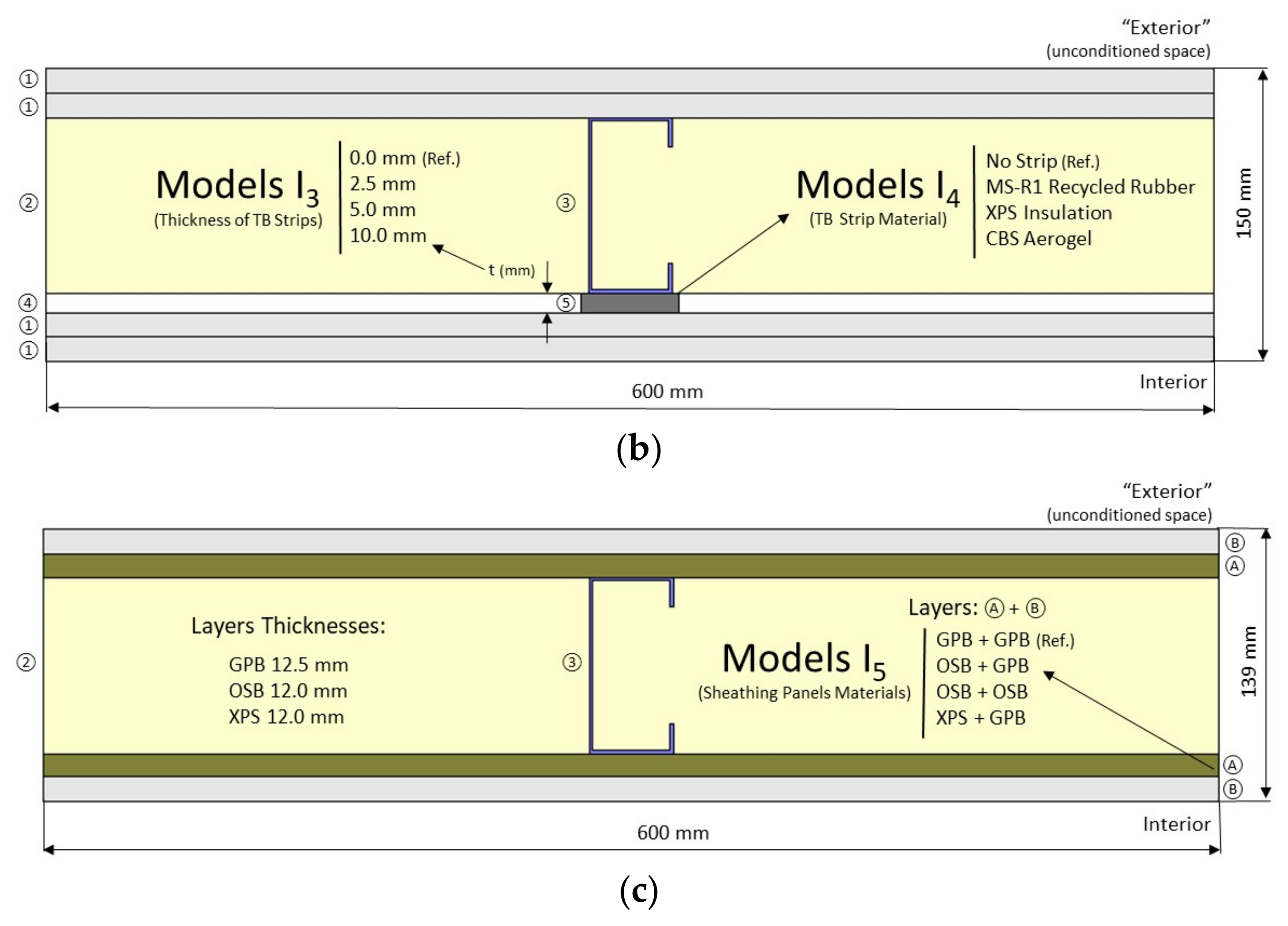
In previous research works there was a lack of research on both interior partitions and exterior facade LSF walls, as well as the thermal performance comparison between them. In this work the thermal transmittance ( U -value) of LSF walls is evaluated by means of a parametric study related with the wall typology (internal partition and external facade) and its composition. The main objective of this study is to quantify the relevance of several parameters in the U -value of LSF partition and facade walls. The evaluated parameters were selected among the most relevant ones and could be easily implemented in practice with used materials available in the market (e.g., recycled rubber, extruded polystyrene (XPS) and aerogel thermal break strips). Moreover, the analyzed LSF wall configurations were newly implemented for this study (i.e., are different from the ones evaluated before by other researchers).
The simulations were performed bi-dimensionally, and the results could be of interest to building developers and researchers, helping them to mitigate thermal bridges and achieving energy savings, whenever an LSF construction system is used. In Portugal (but probably also in other countries) most of the building designers neglect the effect of repetitive thermal bridges due to the steel frame on the thermal transmittance calculations of LSF elements, leading to lower and erroneous U -values. Consequently, the real building energy consumption will be higher than the predicted one in these cases and there is a higher probability of building pathologies related with the occurrence of interstitial condensations.
After this introduction, the evaluated interior and exterior LSF walls are presented, including the reference partition and facade LSF walls and the parameters used in the sensitivity analysis are described. Next, the accuracy of the used 2D FEM algorithm is verified by means of a comparison with ISO 10211 [22] test cases and with the analytical approach, defined in ISO 6946 [11], for a simplified model assuming no steel frame and homogeneous layers. Then, the 2D FEM simulations are explained, including the used boundary conditions and how the air layers were addressed in these simulations. After, the obtained results are presented and discussed for the two LSF wall typologies evaluated. Finally, the main conclusions of this work are presented.

2. Characterization of LSF Interior Walls

2.1. Reference LSF Interior Partition Wall

The reference interior wall is a configuration of an LSF wall normally used as an internal partition within the same dwelling. As illustrated in Figure 2 and listed in Table 1, this LSF internal partition is constituted by two gypsum plasterboards (12.5 mm thick each) on each side of the steel frame (made with steel studs C90, 90 mm wide, and 0.6 mm of steel sheet thickness) and the air cavity is fully filled with mineral wool batt insulation (90 mm). The distance between vertical profiles for internal reference walls was set on 600 mm. The total thickness of this partition wall is 140 mm.
Notice that, even being an internal partition, this LSF wall can separate a conditioned space from an unconditioned space (e.g., a garage), with lower temperature. Therefore, this internal partition also has thermal requirements. Table 1 also displays the thickness ( d ) of each material layer, as well as the thermal conductivity ( λ ) of each material. Usually the sheathing panels (e.g., gypsum plasterboard) are fixed to the LSF structure with metallic self-drilling screws. These fixing bolts were not considered in the simulations since its number is very reduced and the related punctual thermal bridge effect on the overall wall U -value is very reduced and, thus, could be neglected [12].

2.2. Parameters for the Sensitivity Analysis

Table 2 displays the parameters that will be evaluated in the sensitivity analysis, as well as the values to be used for each one. These models and parameters (illustrated in Figure 3) are: the thickness of the steel studs (Model I1); the clearance between steel studs (Model I2); the material and thickness of the thermal break (TB) strips (Model I3); the TB strip materials (Model I4), and; the sheathing panel materials (Model I5). The parameters and values used for each one will be briefly explained in the next paragraphs.
The first parameter to be evaluated was the steel studs thickness used in the wall steel frame (Model I1). The amount of steel inside the wall structure is very relevant because metal has a very high thermal conductivity and its presence in LSF frames create a path that allow the heat to easily cross through the walls, what is known as steel thermal bridges. The reference thickness of the internal partition steel studs is 0.6 mm, which is a usual value for a non-load-bearing partition wall. Steel profiles are also modeled as 1.0, 1.2 and 1.5 mm thick, as this can be found in load-bearing LSF walls (displayed in Table 2 and illustrated in Figure 3a).
The distance between vertical steel studs is another parameter that will be evaluated (Model I2) in order to assess its relevance on the thermal behavior of the LSF internal partitions (Figure 3a). The reference wall has a distance of 600 mm between steel studs (Figure 2), which is the most used clearance given the usual 1.20 m wideness of the sheathing panels. Three more distances will be evaluated in this parametric study, namely 300, 400 and 800 mm (Table 2).
Thermal break is obtained by the insertion of an insulation material (i.e., with a low thermal conductivity), between the steel sections and the innermost layer of the wall, minimizing the heat transfer through the thermal bridges caused by the steel structure and thus, improving/reducing the thermal transmittance ( U -value) of the wall. In this parametric study three different thicknesses for an aerogel thermal break strip will be evaluated, namely 2.5, 5.0 and 10.0 mm (Model I3 in Figure 3b).
Nowadays, several materials are available to be used as thermal break strips in LSF structures, such as recycled rubber (an environmentally friendly solution), XPS (a cheaper solution) and aerogel (a state-of-the-art insulation material with very low thermal conductivity). In this assessment three different materials were tested as thermal break strips (see Model I4 in Figure 3b), namely: recycled rubber [36], extruded polystyrene (XPS) and cold break strip (CBS) aerogel [37], as displayed in Table 2. The thicknesses of the thermal break strips are 10.0 mm and thermal conductivities are listed in Table 3.
To verify the influence of sheathing panel materials (Model I5), several configurations were modeled for the internal walls as shown in Table 2 and displayed in Figure 3c. The sheathing panels in the reference LSF wall are two gypsum plasterboard panels on each side of the steel structure. On the first parameter variation the inner gypsum plasterboard was replaced by one OSB panel in both sides of the LSF structure. On the second parameter variation, both gypsum plasterboards were replaced by two OSB panels on each side. Regarding the third parameter variation, the inner OSB panel was replaced by one XPS panel with the same thickness (12.0 mm), as illustrated in Figure 3c.

3. Characterization of LSF Exterior Walls

3.1. Reference LSF Exterior Facade Wall

The reference exterior wall is an LSF wall normally used for facades, which means that it is a wall that must be prepared to handle high gradients of environment temperature. Therefore, it has an extra thermal insulation layer which was placed on its outside surface. In this case, ETICS (external thermal insulation composite system) using EPS (expanded polystyrene) was chosen as the main insulation material (50 mm thick).
The steel structure that forms the wall frame is made of galvanized cold-formed steel studs and, different for internal walls, the thickness of the steel profile sheet is now 1.5 mm; since this kind of wall is very often a load bearing wall, C90 vertical studs were adopted. Similar to the interior LSF walls, the distance between the vertical profiles for the reference wall is 600 mm. The horizontal cross-section that shows all the layers of the reference exterior LSF wall is illustrated in Figure 4 and the specifications and characteristics of internal composition materials are detailed in Table 4.

3.2. Parameters for Sensitivity Analysis

The parameters and the values that were evaluated in the sensitivity analysis are displayed in Table 5 and illustrated in Figure 5.
The thickness of steel studs used on LSF wall steel frame is the first parameter that will be evaluated (Models E1). The reference value was 1.5 mm and the three additional thicknesses assessed were: 0.6, 1.0 and 1.2 mm (Figure 5a).
Similar to interior partition walls, for exterior facade walls the influence of clearance between the vertical steel studs were also quantified (Models E2). The reference LSF wall has 600 mm of distance between studs and the following clearances were also modeled: 300, 400 and 800 mm (Figure 5a).
Regarding the thermal break strips (Figure 5b), their thickness (Models E3) and materials (Models E4) were the same as for interior partition walls (Figure 3b).
To verify the influence of internal sheathing panels, the exterior wall model was tested in different innermost layer configurations, as shown in Table 5 and illustrated in Figure 5c (Models E5). The reference exterior facade wall has one OSB and one gypsum plasterboard panel as the innermost layer. Notice that these OSB panels are very important in load bearing walls because they give extra resistance to horizontal lateral loads [42]. On the first variation (Value 1), the sheathing panels are composed of two OSBs. For the second variation (Value 2), the internal layers are formed by two gypsum plasterboards (GPBs). In the third variation (Value 3) the OSB panel is replaced by one XPS panel with the same thickness (12.0 mm).
ETICS insulation layer thickness has a great influence on the thermal performance of the external walls. Therefore, this parameter influence will be also evaluated (Models E6). The EPS insulation thickness of the reference exterior LSF wall is 50 mm (Table 5). Three more values will be evaluated, namely: 0.0 mm (i.e., no EPS thermal insulation), 30 and 80 mm (Figure 5c).

4. Verification of 2D FEM Models

In this section the accuracy of the two-dimensional (2D) finite element method (FEM) models used in these computations is verified. First, the numerical results are compared against the two 2D test cases presented in ISO 10211 [22] and implemented by the authors. Then, the numerical 2D results are compared with the analytical solution provided by ISO 6946 [11] for simplified wall models with homogeneous layers (i.e., without LSF structure).

4.1. ISO 10211 Test Cases

To verify the accuracy of two-dimensional calculation algorithms, the ISO 10211 [22] Annex C, provides two test cases reference values (case 1 and 2) that was applied to the 2D FEM THERM software [43] to be classified as a steady-state high precision method.
In the first test case a sketch of a half square column with 28 points placed equidistantly inside the column, for which the corresponding temperatures for each point are known, was provided. The difference between the analytical solution given for each point inside the column and the temperature computed by the algorithm should not exceed 0.1 °C. For all the 28 points provided, the temperatures calculated by THERM (Figure 6a) were the same, with one exception, but stayed below a 0.1 °C difference from the given reference temperature.
For the second case, ISO 10211 requires that the difference between the temperatures calculated by the method being verified and the reference temperatures listed in the standard shall not exceed 0.1 °C, and the difference between the heat flow calculated and the reference value shall not exceed 0.1 W/m. The temperatures (Figure 6b) and heat flow calculated by THERM for test case 2 were exactly the same as prescribed by ISO 10211 Annex C. Notice that these results ensure not only the precision of the THERM software algorithm [43], but also the authors’ expertise to use it.

4.2. ISO 6946 Analytical Approach

Another way to check the reliability of 2D FEM models is to compare the numerical results obtained with a simplified model of the same wall composed only for homogeneous layers (i.e., without the steel frame). For those walls with homogeneous layers, analytical solutions are available in ISO 6946 [11] and easy to calculate based on the thickness of each layer and on the material thermal conductivities. The input values (i.e., materials, layer thicknesses and thermal conductivities) were presented before in Table 1 (reference LSF interior partition wall) and Table 4 (reference LSF exterior facade wall). Regarding surface thermal resistances, the used values were obtained in ISO 6946 [11] for horizontal heat flow, namely 0.13 and 0.04 m2.K/W for internal ( R s i ) and external surfaces ( R s e ), respectively.
The obtained thermal transmittance values for the analytical [11] and numerical approach (2D FEM) are displayed in Table 6. These results once again ensure the authors’ skills in using THERM software for modeling [43], as well as its high accuracy.

5. Two-Dimensional FEM Simulations

5.1. Boundary Conditions

As a mandatory entry to perform a numerical modeling simulation, it is necessary to define the boundary conditions to be applied on the LSF walls. Regarding temperatures, the interior temperature was set at 20 °C (a usual winter indoor comfort set-point temperature) and the exterior temperature was 0 °C (a usual design outdoor temperature for the winter season in mild climates such as in Portugal). An additional temperature of 10 °C was set for the partition walls ‘exterior’ unconditioned space; this value was considered an intermediate temperature between the adopted indoor (20 °C) and outdoor (0 °C) temperatures. Notice, that the obtained U -values do not depend on the chosen temperature difference between the interior and exterior environments, since this value is computed for a unitary temperature difference (i.e., per degree Celsius (°C) or, according to international standard units, per Kelvin (K).
Regarding surface thermal resistances, the values set on ISO 6946 [11] for horizontal heat flow were used (i.e., 0.13 and 0.04 m2.K/W for internal ( R s i ) and external resistance ( R s e ), respectively). Notice that for the interior partition walls, internal surface resistances were used in both sides of the partition (i.e., 0.13 m2.K/W).

5.2. Modeling Air Layers

The air layers inside the walls were modeled with a solid-equivalent thermal conductivity. The thermal resistance for these unventilated air-gaps were obtained in the ISO 6946 [11]. Knowing the thickness of the air-gap and dividing by its tabulated thermal resistance, the solid-equivalent thermal conductivity used in the 2D FEM numerical simulations was obtained, as displayed in Table 7.

6. Results and Discussion

6.1. Interior LSF Partition Walls

Table 8 displays the obtained thermal transmittances values for interior LSF partition walls, as well as the differences in relation to the reference LSF partition wall. To facilitate the quick analysis, the same results are illustrated graphically in Figure 7.
Comparing the obtained thermal transmittance value for the interior reference partition wall without steel frame (Table 6, 0.321 W/(m2.K)) and the calculated value for the reference interior LSF partition wall (Table 8, 0.449 W/(m2.K)) it is possible to verify that the LSF metallic structure increases the thermal transmittance value by about 40% (i.e., +0.128 W/(m2.K)). Notice that this large increase in the U -value is due to the high thermal conductivity of steel (see Table 1)—even for a very small steel thickness (only 0.6 mm)—and due to the fact that all thermal insulation (mineral wool) is bridged by the steel studs (i.e., it is not continuous).
The thickness of steel studs (Model I 1 ) was the first parameter to be assessed (Table 8). As expected, given the higher amount of steel, when increasing the thickness from 0.6 mm (reference value) up to 1.0, 1.2 and 1.5 mm, there was an increase in the U -value of 5.6%, 7.3% and 9.4%, respectively.
The second parameter evaluated (Table 8) was the distance between the vertical studs (Model I 2 ), with the reference value equal to 600 mm. The decrease of this distance to 300 and 400 mm brought an increase in the wall U -value of 29.2% and 14.7%, respectively. This was expected given the increased amount of steel per unit area of the LSF wall. On the other hand, the increase of this distance from 600 mm up to 800 mm brought a wall U -value decrease of about 6.5%.
The existence of a thermal break (TB) strip (Model I 3) increases the insulation of the steel structure and consequently decreases the thermal transmittance of the wall, as expected (Table 8). This U -value reduction was 7.6%, 12.7% and 16.7% for an aerogel TB strip with a thickness of 2.5, 5.0 and 10.0 mm, respectively.
The influence of the TB strip material (10 mm thick) was also evaluated (Model I 4 ). Using recycled rubber (MS-R1) as a thermal break material, the U -value reduction was about 6.2% compared with the reference wall model without the TB strip (Table 8). For an XPS TB strip, the U -value decreased 11.8% and when using a material with a lower thermal conductivity (CBS aerogel) the wall thermal transmittance dropped even more (−16.7%). The former material (aerogel) provided the best results but is still quite an expensive material in comparison with the other two (recycled rubber and XPS).
Three variations according to what was previously presented for Model I5 (Table 2) were proposed for the configurations of sheathing panels. All three modeled variations for sheathing panels show better results than the reference interior LSF wall, because gypsum plasterboard has the highest thermal conductivity value, providing the uppermost U -value for the reference interior LSF partition wall (Table 8). The U -value reduction varied from 6.7% for GPB and OSB panels up to 24.7% for GPB and XPS panels. The largest reduction was expected given the very reduced thermal conductivity of XPS material (0.037 W/(m.K)) in comparison with others [i.e., GPB (0.175 W/(m.K)) and OSB (0.100 W/(m.K))].
Looking now to the extreme values obtained (see highlighted values in Table 8 and Figure 7), the highest thermal transmittance increase (+29.2%) was achieved for the Model I2V1, corresponding to a minimum clearance between steel studs (i.e., 300 mm). The lowest thermal transmittance decrease (−24.7%) was achieved for the Model I5V3, corresponding to GPB and XPS sheathing panels. These extreme U -values verify the great relevance of steel inside the LSF wall (Models I2), as well as the importance of providing a continuous thermal insulation layer (Model I5V3), even with a small thickness (only 12.0 mm in each side). Additionally, this XPS sheathing layer has also the advantage of being an affordable solution when compared with more expensive material (e.g., the aerogel TB strips (Models I3)).
In order to visualize and compare the temperature and heat flux distribution for these models, Figure 8 graphically displays this information. The temperature distribution in both LSF wall cross-sections is very similar (Figure 8a), and the influence of the steel stud in the temperature distribution is visible, given the high thermal conductivity from steel and consequently the thermal bridge effect. Analyzing the heat flux images (Figure 8b), the strong concentration of the heat flux around the steel stud is clear. Moreover, there are higher heat flux values for Model I2V1 (i.e., the wall with 300 mm clearance between studs), in comparison to the other model.

6.2. Exterior LSF Facade Walls

On Table 9 are shown the thermal transmittance values obtained for exterior LSF facade walls, as well as the differences between each parameter U -value and the reference LSF exterior wall U -value. For a better visualization and easier analysis for all modeled parameters, the graphic presented in Figure 9 plotted the obtained U -values and percentage differences.
To evaluate the influence of the steel structure the U -value for the exterior wall with homogeneous layers was compared (i.e., without steel frame, from Table 6, 0.227 W/(m2.K)) with the U -value computed for the complete reference exterior wall (from Table 9, 0.276 W/(m2.K)). The thermal transmittance increase due to the steel frame was 0.049 W/(m2.K) (i.e., +22%, or even only 18% for the 0.6 mm thick (Model E1V1)). Notice that this increment in the U -value is much lower when compared with the interior partition wall: +0.128 W/(m2.K) or +40%. This reduced relevance of the steel structure in the exterior partition wall, even having a steel thickness almost triple from the interior wall (1.5 mm instead of 0.6 mm), could be justified by the continuous thermal insulation in the ETICS (hybrid LSF structure), while in the interior partition wall all the thermal insulation is bridged by the steel frames (cold LSF structure).
Looking to the importance of the steel studs thickness in this exterior facade wall (Model E1), when this thickness is reduced from 1.5 mm to 0.6 mm there is a decrease of only 3.3% in the thermal transmittance (Table 9), while in the interior partition wall the corresponding value when there is an increase in the steel thickness from 0.6 mm up to 1.5 mm is +9.4% (Table 8). This again confirms the higher relevance of the steel structure in the interior partition wall.
The second evaluated parameter is the clearance between the vertical studs (Model E2), where the reference value is 600 mm. When decreasing the distance between the studs—300 and 400 mm—the wall U -value increases 17.0% and 8.3%, respectively. In contrast, when the studs where placed farther apart (800 mm) the U -value decreases 4.7%. As explained before, those thermal transmittance variations are closely linked with the amount of steel inside each wall configuration.
The results of the thickness variation for the CBS aerogel thermal break strip on exterior facade walls were computed using Model E3 (Table 9). As expected, by increasing the TB thickness to 2.5, 5.0 and 10.0 mm, there was a decrease of the wall U -value by 4.7%, 7.6% and 10.1%, respectively. Confronting these results with similar ones for the interior partition wall (7.6%, 12.7% and 16.7% in Table 8), it can be seen that the decrease in U -values is now considerably lower. This could be justified by the reduced importance of the steel frame in the exterior walls and consequently the effect of the TB strips is also reduced.
Evaluating the effectiveness of different materials for the 10 mm thick TB strip (Model E4), as expected, the aerogel (CBS) strip allowed the biggest reduction on wall thermal transmittance (10.1%), followed by the XPS strip (reduction of 7.2%) and recycled rubber (MS-R1) with a 4.0% decrease on the U -value.
Model E5 (Table 9) shows the results of changing the innermost sheathing panels material. Three different configurations were assessed. The first was composed by two panels of GPB and presented a U -value increase of 2.2%. The second configuration used two panels of OSB and it obtained a U -value reduction of 1.8% in comparison with the reference value. For the last variation, the internal layers were composed of a GPB panel and an XPS panel, having the most significant results (i.e., a reduction of 7.2%). Notice, that this last U -value reduction is significantly lower when compared with the one computed for the interior partition wall (−24.7%). Again, this is related with lower relevance of the steel frame thermal bridge transmission due to the existence of the ETICS continuous thermal insulation in the exterior facade wall. Therefore, the relevance of an extra continuous thermal insulation layer is also reduced.
Model E6 evaluates the influence of the EPS thickness in the ETICS. The exterior reference facade wall has 50 mm of EPS, compared with three additional values of 0, 30 and 80 mm. Clearly this was the most relevant evaluated parameter, leading to an increase of 79% in the U -value (Model E6V1) when there is no exterior thermal insulation and a reduction of 19.2% when the EPS thickness was increased to 80 mm (Model E6V3).
Figure 10 displays the color temperature and heat flux distribution for these two models with the most extreme U -value variation. Regarding the temperature distribution (Figure 10a), the influence of the continuous thermal insulation on Model E6V3 (hybrid LSF structure), with a warmer steel frame temperature in comparison with Model E6V1 (cold frame LSF structure) is very visible. Looking at the heat flux distribution (Figure 10b), as expected, the values for Model E6V1 are visually higher than Model E6V3, given the continuous thermal insulation layer in this second model.

7. Conclusions

In this work, a sensitivity analysis regarding the thermal transmittance ( U -value) was performed for two different types of lightweight steel framed (LSF) walls: interior partition and exterior facade. The numerical results were obtained by using 2D finite element method (FEM) models. The accuracy of these models was verified by comparison with ISO 10211 test cases and with ISO 6946 analytical approach.
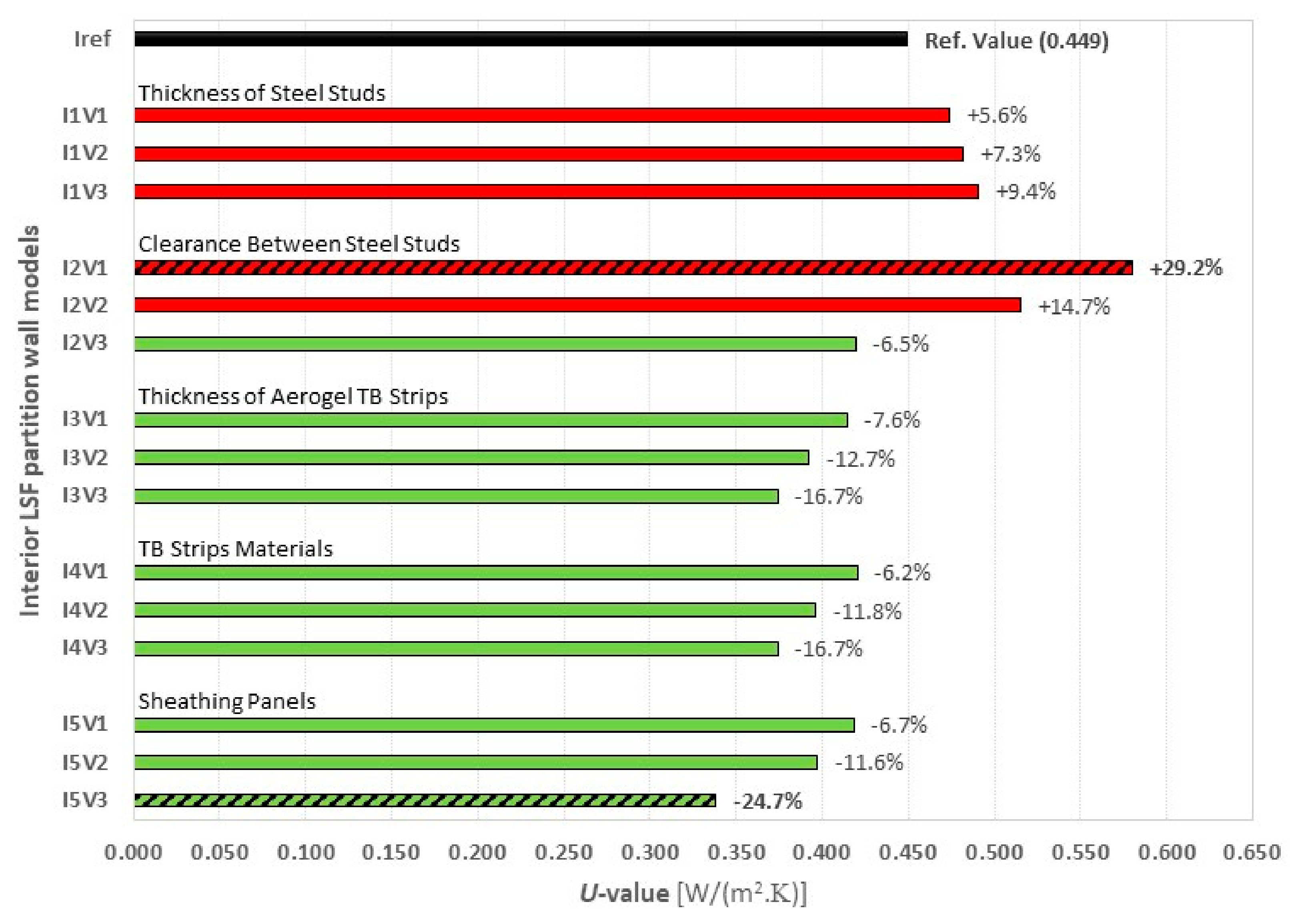
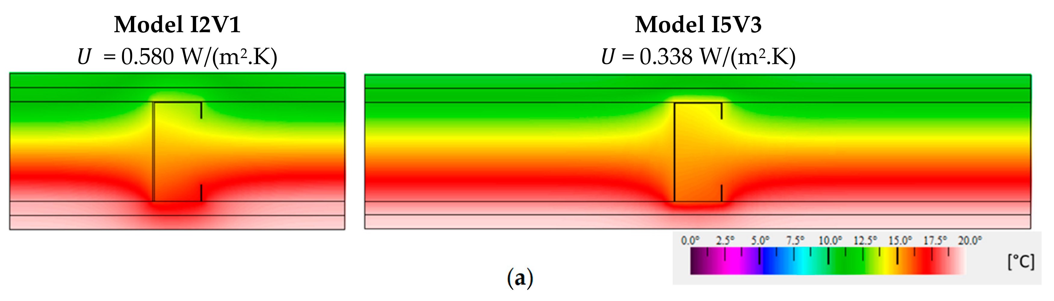
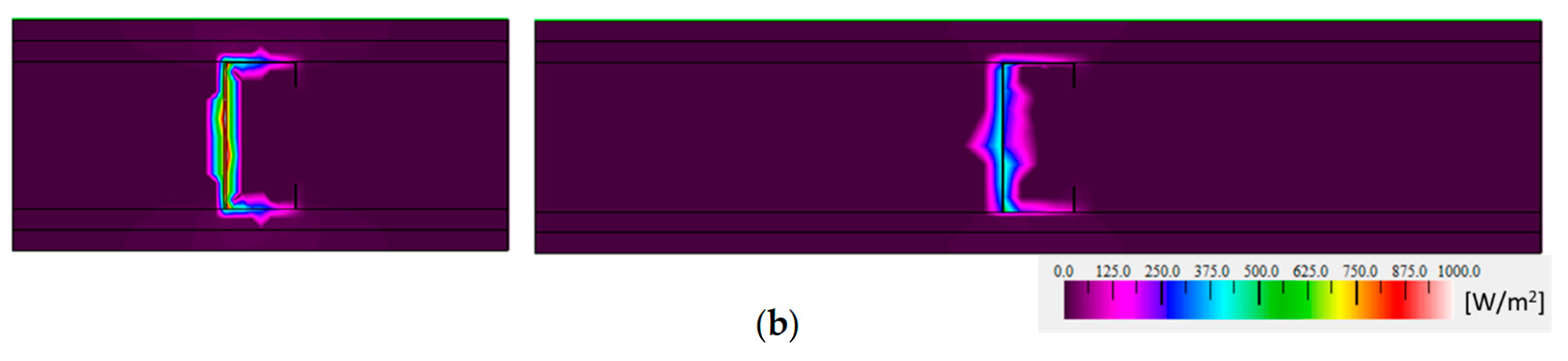
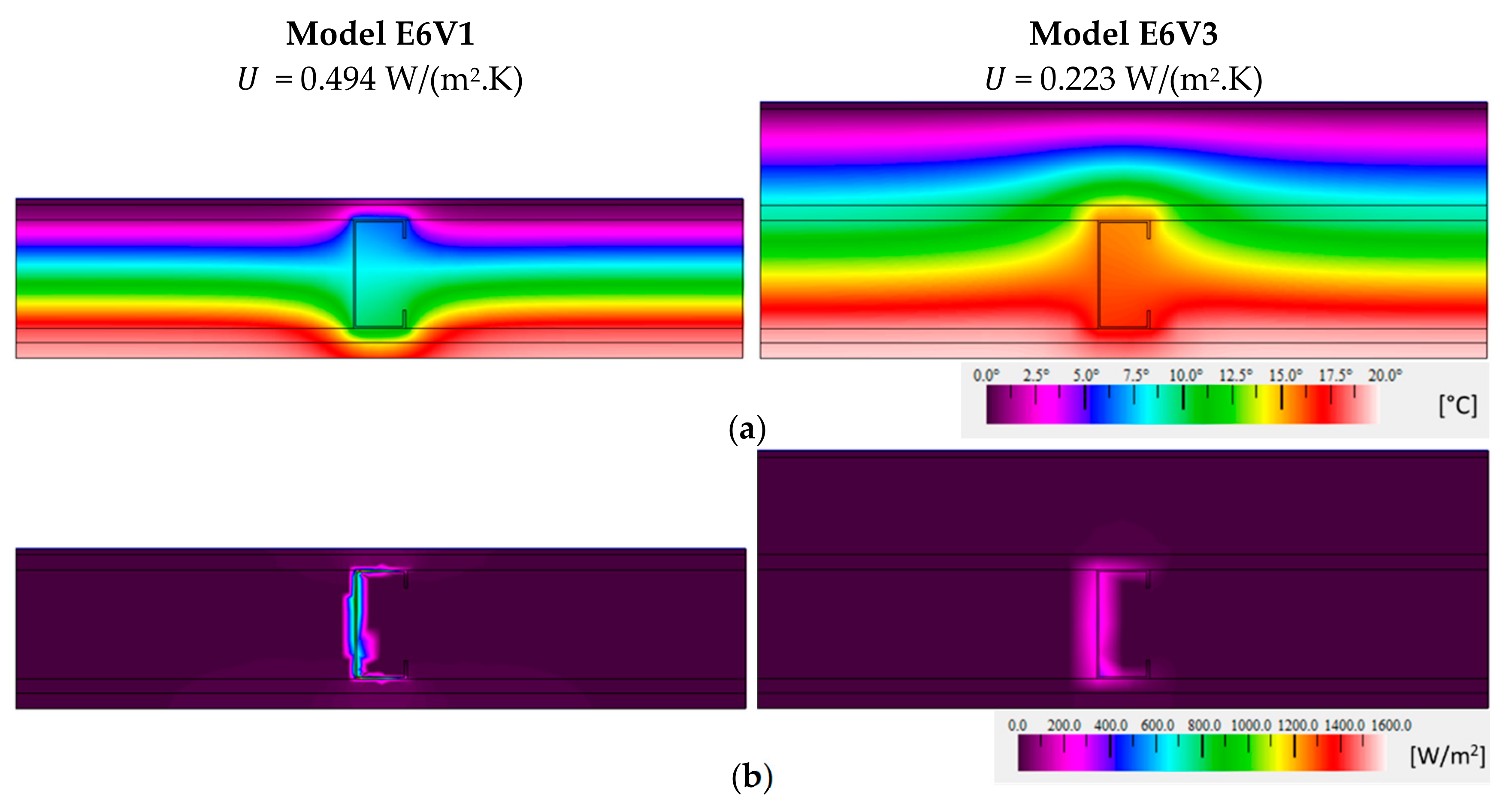
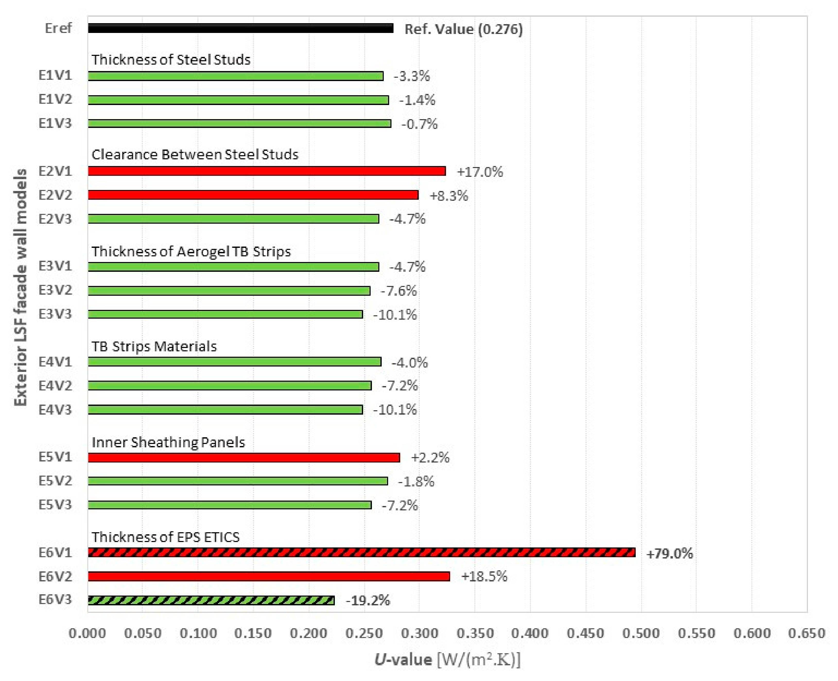
The assessed parameters were: (1) thickness of steel studs; (2) clearance between studs; (3) thermal break strips thickness and (4) material; (5) configuration of internal sheathings panels, and; (6) thickness of EPS external thermal insulation composite system (ETICS), only for the external facade wall. The results of this parametric study were compared to a reference interior partition LSF wall, with a U -value equal to 0.449 W/(m2.K) and to a reference exterior facade LSF wall, with a U -value equal to 0.276 W/(m2.K). Regarding the obtained results, notice that the percentages of U -value change are high, but the absolute differences are rather small in most cases.
The interior partition LSF wall showed higher U -values and a greater influence of the internal steel structure on the wall thermal transmittance. This was expected given the high thermal conductivity of steel and the absence of a continuous thermal insulation on interior partition walls potentiates the thermal bridges’ effects on the LSF structure, resulting in higher U -values. Nevertheless, higher heat flux through the interior walls enables other evaluated parameters to have a greater influence on wall thermal transmittance (e.g., clearance between steel studs (up to +29.2%) and XPS sheathing panel (down to −24.7%)).
The thickness augment of the metallic structure increased the thermal transmittance of the interior wall up to +9.4% (1.5 mm thick). The use of thermal break (TB) strips reduced the U -value of the interior wall down to −16.7% (10 mm thick aerogel strip). The use of different materials in the TB strip was also assessed. The U -value reduction depends on the thermal conductivity of the material used in the TB strip: −6.2% for recycled rubber, −11.8% for XPS and −16.7% for aerogel.
For the exterior facade LSF walls, the existence of an ETICS continuous thermal insulation on the outer side reduces the heat flux through the wall, particularly through the steel frame, resulting in a lower wall U -value and decreasing the importance of other evaluated parameters. In fact, the major and the minor U -value increment changed the thickness of the EPS insulation ETICS layer (i.e., an augment of +79.0% when there is no EPS (0.0 mm thick) and a decrease of −19.2% for 80 mm EPS thickness). Notice that the reference wall has 50 mm of EPS ETICS.
Decreasing the steel thickness (1.5 mm) to 0.6 mm reduced the U -value to only −3.3% (−0.009 W/(m2.K)). Notice that in the interior partition wall the absolute U -value increased, when the steel thickness changed from 0.6 mm up to 1.5 mm, and was more than four times higher (i.e., +0.042 W/(m2.K), showing the lower importance of the steel structure in this exterior facade LSF wall.
When changing the distance between the vertical studs from 600 mm to half (300 mm) and doubling the amount of steel, the U -value increased only +17.0% (+0.047 W/(m2.K)). Notice that in the interior partition wall the absolute U -value increase was almost the triple (i.e., +0.131 W/(m2.K)).
The use of aerogel thermal break strips with different thicknesses (up to 10 mm) reduced the U -value down to −10.1% (−0.028 W/(m2.K)). Notice that in the interior wall this absolute U -value reduction was more than double (i.e., −0.075 W/(m2.K)). Using a 10 mm thick TB strip with different materials (rubber, XPS and aerogel) decreased the U -value to about −4.0% (−0.011 W/(m2.K)), −7.2% (−0.020 W/(m2.K)) and −10.1% (−0.028 W/(m2.K)), respectively. Notice that in the interior wall these U -value reductions were quite higher: −6.2% (−0.028 W/(m2.K)), −11.8% (−0.053 W/(m2.K)) and −16.7% (−0.075 W/(m2.K)), respectively.
The use of different inner sheathing panels (GPB, OSB and XPS) led to a U -value variation down to −7.2% (−0.020 W/(m2.K)) for the XPS/GPB panels. Notice that in the interior LSF wall this absolute U -value reduction was much more relevant [i.e., more than five times higher (−0.111 W/(m2.K))]. This was due not only to the absence of any continuous thermal insulation in the reference interior LSF wall, but also to the fact that in this case the two wall sides were updated with an XPS sheathing panel (one in each side), while in the exterior facade only the inner wall surface was updated with an XPS sheathing panel.
For further related research work, the authors intend to perform laboratorial experimental measurements in similar interior and exterior LSF walls. These measurements will be useful to ensure the reliability of the numerical simulations and validate the numerical models. In order to consider and evaluate the relevance of some three-dimensional (3D) effects in the thermal performance of these interior and exterior LSF walls, the authors also intend to perform some 3D FEM simulations in a complementary future research work. Another predicted future work is to evaluate the cost-benefit of these thermal performance improvement measures and the provided energy efficiency benefits for an LSF building.

Author Contributions

All the authors participated equally to this work.

Funding

This work was financed by FEDER funds through the Competitivity Factors Operational Programme—COMPETE and by national funds through FCT—Foundation for Science and Technology within the scope of the project POCI-01-0145-FEDER-032061.
Energies 12 02671 i001

Acknowledgments

The authors also want to thank the support provided by the following companies: Pertecno, Gyptec Ibérica, Volcalis, Sotinco, Kronospan, Hukseflux and Hilti.

Conflicts of Interest

The authors declare no conflicts of interest.

References

  1. European Union. Directive (EU) 2018/844 of the European Parliament and of the Council of 30 May 2018 amending Directive 2010/31/EU on the energy performance of buildings and Directive 2012/27/EU on energy efficiency. J. Eur. Union 2018, 2018, 75–91. [Google Scholar]
  2. Aslani, A.; Bakhtiar, A.; Akbarzadeh, M.H. Energy-efficiency technologies in the building envelope: Life cycle and adaptation assessment. J. Build. Eng. 2019, 21, 55–63. [Google Scholar] [CrossRef]
  3. Ruparathna, R.; Hewage, K.; Sadiq, R. Improving the energy efficiency of the existing building stock: A critical review of commercial and institutional buildings. Renew. Sustain. Energy Rev. 2016, 53, 1032–1045. [Google Scholar] [CrossRef]
  4. Paone, A.; Bacher, J.P. The impact of building occupant behavior on energy efficiency and methods to influence it: A review of the state of the art. Energies 2018, 11, 953. [Google Scholar] [CrossRef]
  5. Santos, P.; da Silva, L.S.; Ungureanu, V. Energy Efficiency of Light-Weight Steel-Framed Buildings, 1st ed.; Technical Committee 14—Sustainability & Eco-Efficiency of Steel Construction; N. 129; European Convention for Constructional Steelwork (ECCS): Mem Martins, Portugal, 2012; ISBN 978-92-9147-105-8. [Google Scholar]
  6. Pulselli, R.M.; Simoncini, E.; Marchettini, N. Energy and emergy based cost-benefit evaluation of building envelopes relative to geographical location and climate. Build Environ. 2009, 44, 920–928. [Google Scholar] [CrossRef]
  7. Kaynakli, O. A review of the economical and optimum thermal insulation thickness for building applications. Renew. Sustain. Energy Rev. 2012, 16, 415–425. [Google Scholar] [CrossRef]
  8. Soares, N.; Martins, C.; Gonçalves, M.; Santos, P.; da Silva, L.S.; Costa, J.J. Laboratory and in-situ non-destructive methods to evaluate the thermal transmittance and behavior of walls, windows, and construction elements with innovative materials: A review. Energy Build. 2019, 182, 88–110. [Google Scholar] [CrossRef]
  9. Santos, P. Chapter 3—Energy Efficiency of Lightweight Steel-Framed Buildings. In Energy Efficient Buildings; Eng Hwa, Y., Ed.; InTech: Rijeka, Croatia, 2017; pp. 35–60. [Google Scholar]
  10. Roque, E.; Santos, P.; Pereira, A.C. Thermal and sound insulation of lightweight steel-framed façade walls. Sci. Technol. Built Environ. 2019, 25, 156–176. [Google Scholar] [CrossRef]
  11. International Organization for Standardization. Building Components and Building Elements—Thermal Resistance and Thermal—Calculation Methods, International Organization for Standardization; ISO 6946; International Organization for Standardization: Geneva, Switzerland, 2017. [Google Scholar]
  12. Roque, E.; Santos, P. The Effectiveness of Thermal Insulation in Lightweight Steel-Framed Walls with Respect to Its Position. Buildings 2017, 7, 13. [Google Scholar] [CrossRef]
  13. Schiavoni, S.; D’Alessandro, F.; Bianchi, F.; Asdrubali, F. Insulation materials for the building sector: A review and comparative analysis. Renew. Sustain. Energy Rev. 2016, 62, 988–1011. [Google Scholar] [CrossRef]
  14. Gervásio, H.; Santos, P.; da Silva, L.S.; Lopes, A.M.G. Influence of thermal insulation on the energy balance for cold-formed buildings. Adv. Steel Constr. 2010, 6, 742–766. [Google Scholar]
  15. Craveiro, A.; Lopes, A.G.; Santos, P.; da Silva, L.S. Natural ventilation potential on thermal comfort of a light-steel framing residential building. In Proceedings of the Green Design, Materials and Manufacturing Processes, Proceedings of the 2nd International Conference on Sustainable Intelligent Manufacturing, SIM 2013, Lisbon, Portugal, 26–29 June 2013. [Google Scholar]
  16. Soares, N.; Gaspar, A.R.; Santos, P.; Costa, J.J. Multi-dimensional optimization of the incorporation of PCM-drywalls in lightweight steel-framed residential buildings in different climates. Energy Build. 2014, 70, 411–421. [Google Scholar] [CrossRef]
  17. Waqas, A.; Din, Z.U. Phase change material (PCM) storage for free cooling of buildings—A review. Renew. Sustain. Energy Rev. 2013, 18, 607–625. [Google Scholar] [CrossRef]
  18. Rosa, N.; Santos, P.; Costa, J.; Gervásio, H. Modeling and performance analysis of an earth-to-air heat exchanger in a pilot installation. J. Build. Phys. 2018, 42, 259–287. [Google Scholar] [CrossRef]
  19. Valdiserri, P.; Biserni, C.; Garai, M. Energy performance of a ventilation system for an apartment according to the Italian regulation. Int. J. Energy Environ. Eng. 2016, 7, 353–359. [Google Scholar] [CrossRef]
  20. Xu, X.; Feng, G.; Chi, D.; Liu, M.; Dou, B. Optimization of Performance Parameter Design and Energy Use Prediction for Nearly Zero Energy Buildings. Energies 2018, 11, 3252. [Google Scholar] [CrossRef]
  21. Santos, P.; Martins, R.; Gervásio, H.; Silva, L.S. Assessment of building operational energy at early stages of design—A monthly quasi-steady-state approach. Energy Build. 2014, 79, 58–73. [Google Scholar] [CrossRef]
  22. International Organization for Standardization. Thermal Bridges in Building Construction—Heat Flows and Surface Temperatures—Detailed Calculations; ISO 10211; International Organization for Standardization: Geneva, Switzerland, 2017. [Google Scholar]
  23. Santos, P.; Gonçalves, M.; Martins, C.; Soares, N.; Costa, J.J. Thermal Transmittance of Lightweight Steel Framed Walls: Experimental Versus Numerical and Analytical Approaches. J. Build. Eng. 2019, 25, 100776. [Google Scholar] [CrossRef]
  24. Evangelisti, L.; Guattari, C.; Gori, P.; Bianchi, F. Heat transfer study of external convective and radiative coefficients for building applications. Energy Build 2017, 151, 429–438. [Google Scholar] [CrossRef]
  25. Santos, P.; Martins, C.; da Silva, L.S. Thermal performance of lightweight steel-framed construction systems. Metall. Res. Technol. 2014, 111, 329–338. [Google Scholar] [CrossRef]
  26. Soares, N.; Santos, P.; Gervásio, H.; Costa, J.J.; da Silva, L.S. Energy efficiency and thermal performance of lightweight steel-framed (LSF) construction: A review. Renew. Sustain. Energy Rev. 2017, 78, 194–209. [Google Scholar] [CrossRef]
  27. Gorgolewski, M. Developing a simplified method of calculating U-values in light steel framing. Build. Environ. 2017, 42, 230–236. [Google Scholar] [CrossRef]
  28. International Organization for Standardization. Thermal Insulation—Determination of Steady-State Thermal Transmission Properties—Calibrated and Guarded Hot Box, International Organization for Standardization; ISO 8990; ISO—International Organization for Standardization: Geneva, Switzerland, 1994. [Google Scholar]
  29. Atsonios, I.A.; Mandilaras, I.D.; Kontogeorgos, D.A.; Founti, M.A. Two new methods for the in-situ measurement of the overall thermal transmittance of cold frame lightweight steel-framed walls. Energy Build. 2018, 170, 183–194. [Google Scholar] [CrossRef]
  30. Santos, P.; Martins, C.; da Silva, L.S.; Bragança, L. Thermal performance of lightweight steel framed wall: The importance of flanking thermal losses. J. Build. Phys. 2014, 38, 81–98. [Google Scholar] [CrossRef]
  31. De Angelis, E.; Serra, E. Light steel-frame walls: Thermal insulation performances and thermal bridges. Energy Procedia 2014, 45, 362–371. [Google Scholar] [CrossRef]
  32. Martins, C.; Santos, P.; da Silva, L.S. Lightweight steel-framed thermal bridges mitigation strategies: A parametric study. J. Build. Phys. 2016, 39, 342–372. [Google Scholar] [CrossRef]
  33. Gyptec Ibérica. Technical Sheet: Standard Gypsum Plasterboard. 2019. Available online: https://www.gyptec.eu/documentos/Ficha_Tecnica_Gyptec_A.pdf (accessed on 14 March 2019). (In Portuguese).
  34. Volcalis. Technical Sheet: Alpha Mineral Wool. 2019. Available online: https://www.volcalis.pt/categoria_file_docs/fichatecnica_volcalis_alpharolo-253.pdf (accessed on 14 March 2019). (In Portuguese).
  35. Santos, C.; Matias, L. ITE50—Coeficientes de Transmissão Térmica de Elementos da Envolvente dos Edifícios; LNEC—Laboratório Nacional de Engenharia Civil: Lisbon, Portugal, 2006. (In Portuguese) [Google Scholar]
  36. MS-R1. Acousticork MS-R1 Recycled Rubber. 2017. Available online: https://amorimcorkcomposites.com/media/1334/acousticork-book-en.pdf (accessed on 14 March 2019).
  37. Spacetherm. Technical Sheet: Cold Bridge Strip. 2018. Available online: https://www.proctorgroup.com/assets/Datasheets/Spacetherm_CBS_Datasheet.pdf (accessed on 14 March 2019).
  38. ITeCons. Test Report HIG 363/12—Determination of Thermal Resistance; Instituto de Investigação e Desenvolvimento em Ciências da Construção: Coimbra, Portugal, 2012. [Google Scholar]
  39. WeberTherm Uno. Technical Specifications: Weber Saint-Gobain ETICS Finish Mortar. 2018. Available online: https://www.pt.weber/files/pt/2019-04/FichaTecnica_weberthermuno.pdf (accessed on 14 March 2019). (In Portuguese).
  40. TincoTerm. Technical Sheet: EPS 100. 2015. Available online: http://www.lnec.pt/fotos/editor2/tincoterm-eps-sistema-co-1.pdf (accessed on 14 March 2019). (In Portuguese).
  41. KronoSpan. Technical Sheet: KronoBuild OSB 3. 2019. Available online: https://de.kronospan-express.com/public/files/downloads/kronobuild/kronobuild-en.pdf (accessed on 14 March 2019).
  42. Henriques, J.; Rosa, N.; Gervasio, H.; Santos, P.; Simões, L. Structural performance of light steel framing panels using screw connections subjected to lateral loading. Thin Walled Struct. 2017, 121, 67–88. [Google Scholar] [CrossRef]
  43. THERM. Software Version 7.6.1; Lawrence Berkeley National Laboratory, United States Department of Energy: Berkeley, CA, USA, 2017. Available online: https://windows.lbl.gov/software/therm (accessed on 14 February 2019).
Figure 1. Thermal bridge’s effect due to vertical steel studs in a light steel framed (LSF) wall captured in an infrared thermal image [30].
Energies 12 02671 g001
Figure 2. Cross-section of an interior LSF reference partition wall modeled on THERM software.
Energies 12 02671 g002
Figure 3. Interior LSF partition cross-sections: (a) Models I1 and I2; (b) Models I3 and I4; (c) Model I5. Layers: ① gypsum plasterboard (GPB); ② mineral wool; ③ steel stud C90; ④ air layer; ⑤ TB strip.
Energies 12 02671 g003aEnergies 12 02671 g003b
Figure 4. Cross-section of an exterior LSF reference wall modeled on THERM software.
Energies 12 02671 g004
Figure 5. Exterior LSF facade cross-sections: (a) Models E1 and E2; (b) Models E3 and E4; (c) Models E5 and E6. Layers: ① ETICS finish; ② EPS; ③ OSB; ④ mineral wool; ⑤ steel stud C90; ⑥ gypsum plasterboard (GPB); ⑦ air layer; ⑧ TB strip.
Energies 12 02671 g005
Figure 6. Temperature distribution obtained by the authors for the 2D test cases of ISO 10211 [22]: (a) test case 1; (b) test case 2.
Energies 12 02671 g006
Figure 7. Thermal transmittances obtained for interior LSF partition walls.
Energies 12 02671 g007
Figure 8. Temperature (a) and heat flux (b) color distribution for internal LSF wall models with the highest U -value increase (300 mm vertical stud distance) and decrease (XPS + GPB sheathing panels).
Energies 12 02671 g008aEnergies 12 02671 g008b
Figure 9. Thermal transmittances obtained for exterior LSF facade walls.
Energies 12 02671 g009
Figure 10. Temperature (a) and heat flux (b) color distribution for exterior LSF wall models with the highest U -value increase (0 mm EPS ETICS) and decrease (80 mm EPS ETICS).
Energies 12 02671 g010
Table 1. Materials, thicknesses ( d ) and thermal conductivities ( λ ) of the LSF interior reference partition wall.
Material (From Outer to Innermost Layer) d [mm] λ [W/(m.K)] Ref.
GPB 1 (2 × 12.5 mm)250.175[33]
Mineral wool900.035[34]
Steel stud (C90 × 43 × 15 × 0.6 mm)9050.000[35]
GPB 1 (2 × 12.5 mm)250.175[33]
Total Thickness140--
1 GPB—gypsum plasterboard.
Table 2. Interior partition LSF wall: models and parameter values to be evaluated.
ModelEvaluated ParameterRef. ValueValue 1Value 2Value 3
I1 Thickness of Steel Studs [mm]0.61.01.21.5
I2 Clearance Between Steel Studs [mm]600300400800
I3 Thickness of Aerogel TB 1 Strips [mm]0.02.55.010.0
I4 Material of TB 1 Strips with 10 mm-MS-R1 2XPS 3CBS 4
I5 Sheathing Panels Materials
GPB 5 Thickness [mm] 2 × 12.512.5-12.5
OSB 6 Thickness [mm]-12.02 × 12.0-
XPS 3 Thickness [mm] ---12.0
1 TB—thermal break; 2 MS-R1—Acousticork (recycled rubber); 3 XPS—extruded polystyrene; 4 CBS—cold break strip (aerogel); 5 GPB—gypsum plasterboard; 6 OSB—oriented strand board.
Table 3. Thermal conductivities ( λ ) of thermal break strips (10.0 mm thick).
Material λ [W/(m.K)] Ref.
Recycled Rubber (Acousticork MS-R1) 0.122[38]
XPS 1 Insulation0.037[35]
CBS 2 Aerogel0.015[37]
1 XPS—extruded polystyrene; 2 CBS—cold break strip.
Table 4. Materials, thicknesses ( d ) and thermal conductivities ( λ ) of the reference exterior facade wall.
Material (From Outer to Innermost Layer) d [mm] λ [W/(m.K)] Ref.
ETICS 1 finish50.450[39]
EPS 2500.036[40]
OSB 3120.100[41]
Mineral wool900.035[34]
Steel stud (C90 × 43 × 15 × 1.5 mm)9050.000[35]
OSB 3120.100[41]
GPB 412.50.175[33]
Total Thickness181.5--
1 ETICS—external thermal insulation composite system; 2 EPS—expanded polystyrene; 3 OSB—oriented strand board; 4 GPB—gypsum plasterboard.
Table 5. Exterior facade LSF wall: models and parameters values to be evaluated.
ModelEvaluated ParameterRef. ValueValue 1Value 2Value 3
E1 Thickness of Steel Studs [mm]1.50.61.01.2
E2 Clearance Between Steel Studs [mm]600300400800
E3 Thickness of Aerogel TB 1 Strips [mm]0.02.55.010.0
E4 Material of TB 1 Strips with 10 mm-MS-R1 2XPS 3CBS 4
E5 Inner Sheathing Panels Materials
GPB 5 Thickness [mm] 12.5-2 × 12.512.5
OSB 6 Thickness [mm]12.02 × 12.0--
XPS 7 Thickness [mm] ---12.0
E6 Thickness of EPS 8 ETICS 9 [mm]500.03080
1 TB—thermal Break; 2 MS-R1—Acousticork (recycled rubber); 3 XPS—extruded polystyrene; 4 CBS—cold break strip (aerogel); 5 GPB—gypsum plasterboard; 6 OSB—oriented strand board; 7 XPS—extruded polystyrene; 8 EPS—expanded polystyrene; 9 ETICS—external thermal insulation composite system.
Table 6. Thermal transmittances obtained for simplified wall models with homogeneous layers.
Wall Typology (Without Steel Frame) U -Value [W/(m2.K)]
Analytical2D FEM 1
Interior Reference Partition Wall 0.3210.321
Exterior Reference Facade Wall0.2270.227
1 using THERM software [43].
Table 7. Thermal resistance and solid-equivalent thermal conductivity of air layers.
d air 1   [ mm ] R air 2   [ m 2 . K / W ] λ e q 3   [ W / ( m . K ) ]
2.50.0550.045
5.00.110.045
10.00.150.067
90.00.180.500
1 d air —thickness of air layer; 2 R air —thermal resistance of air layer (from ISO 6946); 3 λ eq —solid-equivalent thermal conductivity.
Table 8. Thermal transmittance obtained for interior LSF partition walls.
ModelEvaluated ParameterRef. ValueValue 1Value 2Value 3
I1Thickness of Steel Studs [mm]0.61.01.21.5
U -value [W/(m2.K)]0.4490.4740.4820.491
Absolute difference-+0.025+0.033+0.042
Percentage difference-+5.6%+7.3%+9.4%
I2Clearance Between Steel Studs [mm]600300400800
U -value [W/(m2.K)]0.4490.5800.5150.420
Absolute difference-+0.131+0.066−0.029
Percentage difference-+29.2%+14.7%−6.5%
I3Thickness of Aerogel TB 1 Strips [mm]0.02.55.010.0
U -value [W/(m2.K)]0.4490.4150.3920.374
Absolute difference-−0.034−0.057−0.075
Percentage difference-−7.6%−12.7%−16.7%
I4TB 1 Strips Materials [10 mm]-MS-R1 2XPS 3CBS 4
U -value [W/(m2.K)]0.4490.4210.3960.374
Absolute difference-−0.028−0.053−0.075
Percentage difference-−6.2%−11.8%−16.7%
I5Sheathing Panels
GPB 5 Thickness [mm]2 × 12.512.5-12.5
OSB 6 Thickness [mm]-12.02 × 12.0-
XPS 3 Thickness [mm]---12.0
U -value [W/(m2.K)]0.4490.4190.3970.338
Absolute difference-−0.030−0.052−0.111
Percentage difference-−6.7%−11.6%−24.7%
1 TB—thermal Break; 2 MS-R1—Acousticork (rubber); 3 XPS—extruded polystyrene; 4 CBS—cold break strip (aerogel); 5 GPB—gypsum plasterboard; 6 OSB—oriented strand board.
Table 9. Thermal transmittances obtained for exterior LSF facade walls.
ModelEvaluated ParameterRef. ValueValue 1Value 2Value 3
E1Thickness of Steel Studs [mm]1.50.61.01.2
U -value [W/(m2.K)]0.2760.2670.2720.274
Absolute difference-−0.009−0.004−0.002
Percentage difference-−3.3%−1.4%−0.7%
E2Clearance Between Steel Studs [mm]600300400800
U -value [W/(m2.K)]0.2760.3230.2990.263
Absolute difference-+0.047+0.023−0.013
Percentage difference-+17.0%+8.3%−4.7%
E3Thickness of Aerogel TB 1 Strips [mm]0.02.55.010.0
U -value [W/(m2.K)]0.2760.2630.2550.248
Absolute difference-−0.013−0.021−0.028
Percentage difference-−4.7%−7.6%−10.1%
E4TB1 Strips Materials [10 mm]-MS-R1 2XPS 3CBS 4
U -value [W/(m2.K)]0.2760.2650.2560.248
Absolute difference-−0.011−0.020−0.028
Percentage difference-−4.0%−7.2%−10.1%
E5Inner Sheathing Panels
GPB 5 Thickness [mm]12.52 × 12.5-12.5
OSB 6 Thickness [mm]12.0 2×12.0-
XPS 3 Thickness [mm]---12.0
U -value [W/(m2.K)]0.2760.2820.2710.256
Absolute difference-+0.006−0.005−0.020
Percentage difference-+2.2%−1.8%−7.2%
E6Thickness of EPS 7 ETICS 8 [mm]5003080
U -value [W/(m2.K)]0.2760.4940.3270.223
Absolute difference-+0.218+0.051−0.053
Percentage difference-+79.0%+18.5%−19.2%
1 TB—thermal break; 2 MS-R1—Acousticork (rubber); 3 XPS—extruded polystyrene; 4 CBS—cold break strip (aerogel); 5 GPB—gypsum plasterboard; 6 OSB—oriented strand board; 7 EPS—expanded polystyrene: 8 ETICS—external thermal insulation composite system.

