Article

A New Outer-Rotor Hybrid-Excited Flux-Switching Machine Employing the HTS Homopolar Topology

1
School of Mechanical Engineering, Korea University, Seoul 02841, Korea
2
Spin Engineering Physics Team, Korea Basic Science Institute, Daejeon 34133, Korea
3
Industry Convergence Technology Center, Korea Testing Laboratory, Ansan 426-910, Korea
*
Author to whom correspondence should be addressed.
Energies 2019, 12(14), 2654; https://doi.org/10.3390/en12142654
Submission received: 13 May 2019 / Revised: 7 July 2019 / Accepted: 8 July 2019 / Published: 10 July 2019
(This article belongs to the Special Issue Design, Control, and Optimization of Flux Switching Machine)

Abstract

:
Currently, studies of flux switching machines are actively underway owing to several advantages of these machines, including their sturdy rotor structure and high output capability. This paper deals with an outer-rotor hybrid-excited flux-switching machine (FSM). The proposed machine embraces a homopolar structure and utilizes permanent magnets (PMs) for field excitation and a high-temperature superconducting (HTS) coil for flux regulation. The stator houses the HTS field coil, PMs, and armature windings. The outer rotor consists solely of an iron core. Thus, the machines are cost effective and can serve as a solution to the design and fabrication complexities of field current supplying and cooling systems. In this paper, the machine performance outcomes are analyzed using the 3D finite element method (FEM), and the validity of the proposed machine is verified.

1. Introduction

In many variable-speed rotating synchronous machine applications such as aircraft, electric propulsion, and wind turbines, constant output (torque or voltage) operation is required [1,2,3]. In a conventional synchronous machine with field windings, this type of operation is realized by the regulation of the field current as the speed increases. However, permanent magnet (PM) machines use a constant magnetic field by PMs, and the flux can be regulated by armature reaction flux [4,5]. In PM machines, the armature reaction flux can be controlled by a converter. This causes a decrease in the efficiency of the machine due to a significant increase in the winding losses. A hybrid type of excitation topology has an advantage in variable-speed synchronous machine applications because it allows adjustments of the excitation field, unlike the conventional PM excitation topology. Accordingly, studies which apply a hybrid excitation topology to a synchronous machine are actively underway [6,7,8,9,10,11,12,13]. Flux switching machines (FSMs) are one type of synchronous machine. Flux switching machines use a structure in which the armature winding and excitation components are located in a stationary part. The machines have a sturdy rotor structure and performance capabilities comparable to those of conventional PM machines [14,15,16,17,18,19]. However, conventional hybrid excited FSMs have an inner-rotor structure. Therefore, the field windings for flux regulation are located in the outer-stator, and the number of field coils also depends on the number of PMs [7,8,9,10,11,12,13]. This makes it difficult to apply a superconducting field coil that requires a cryogenic cooling system. In this paper, a novel outer-rotor hybrid excited PM FSM is proposed. The proposed FSM adopts a homopolar iron-core with a high temperature superconducting (HTS) field coil. The homopolar topology can make the HTS field coil and the cryogenic cooling system more robust because the HTS field coil can be configured as one system in the center of the stationary iron core [20,21,22]. The key features of the proposed machine can be summarized as follows.
(1)
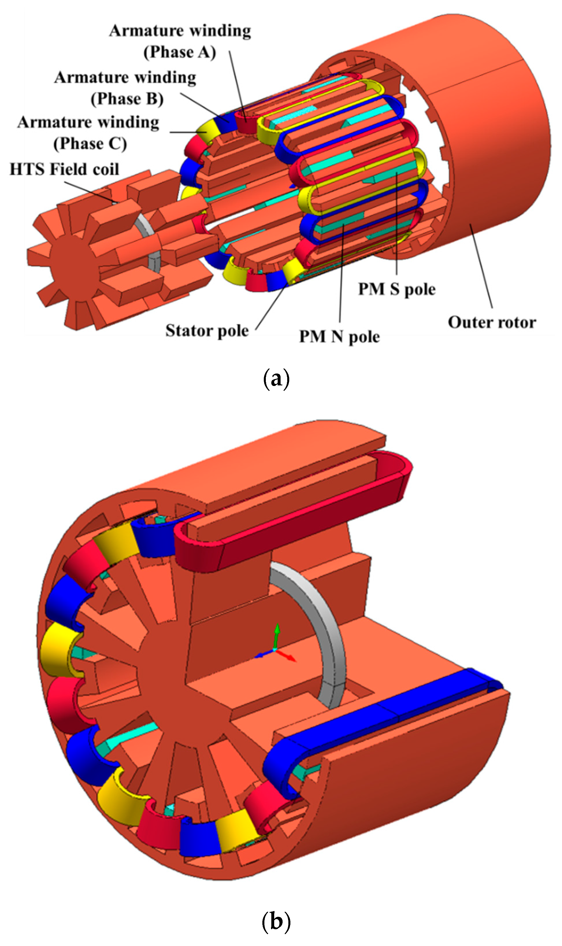
The main magnetic flux is generated by the PMs and switching of the field polarities in the rotor tooth, for the rotating magnetic field is realized through the flux-switching topology.
(2)
It adopts HTS coil excitation and homopolar topology for flux regulation.
(3)
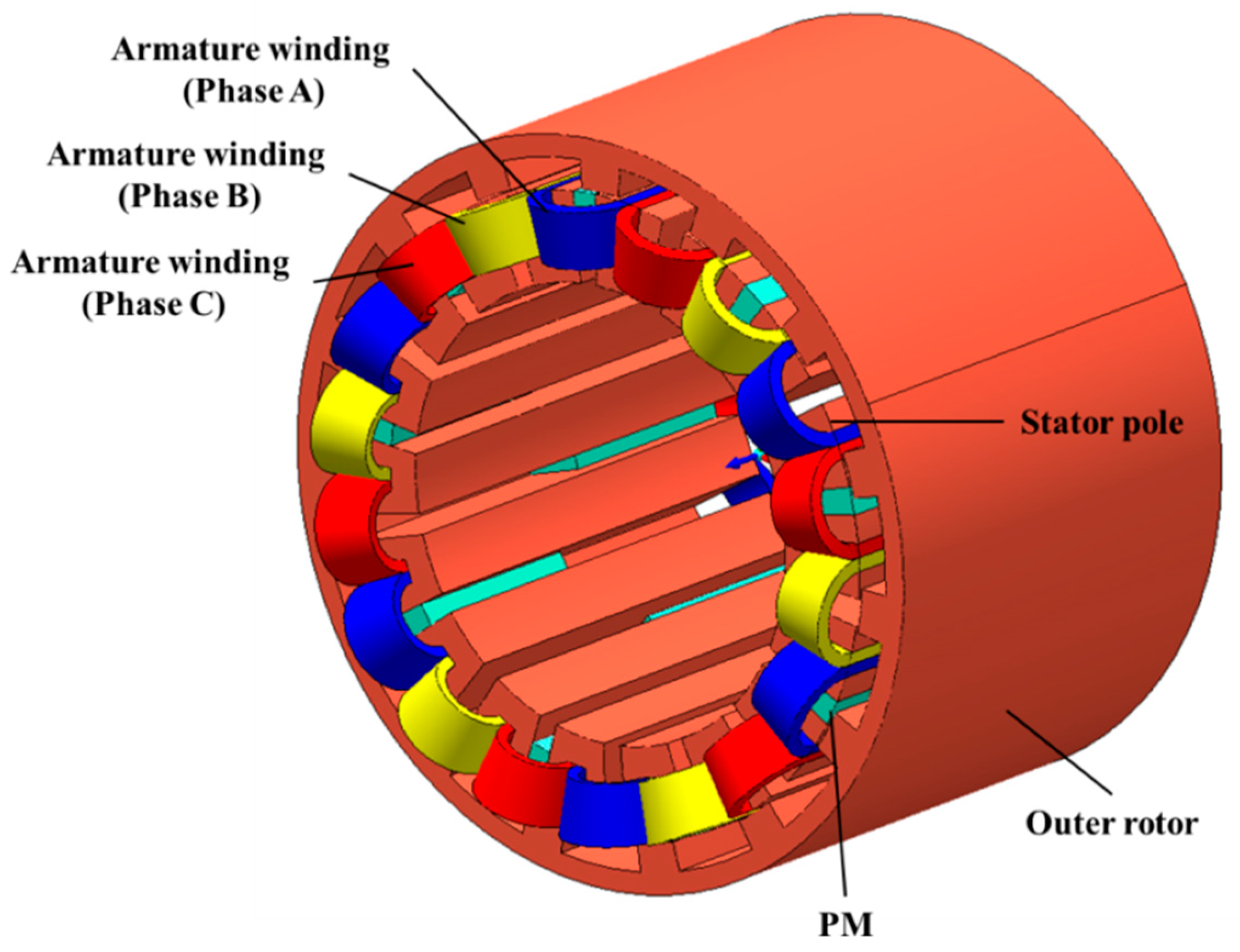
All components such as armature winding, HTS field coil, and PMs, except outer-rotor, are located in the inner stator.
(4)
The outer rotor consists only of the iron-core with tooth.
The HTS field coil can create a very high field compared to a conventional copper coil, thus further enhancing the flux regulation capability. Therefore, this hybrid excitation topology makes the machine more attractive. Moreover, it has the advantage of improving the torque and power capability. This paper describes the operating principle and design of the proposed machine. The designed machine has a three-phase concept around an 18-tooth stator with 15 rotor poles. For designing the machine, basic parameters were derived by utilizing mathematical formulas, then it was modeled and simulated on 3D finite element analysis software, MagNet ver. 7.6. Then the design refinement technique was implemented through a deterministic approach. Recently, many researches on design optimization of the FSMs have been carried out [23,24,25,26,27]. However, researches on the FSM mainly has concerned the electromagnetic optimization of the inner-rotor type machines, with scarcely few giving careful consideration to the outer-rotor configuration. This paper primarily focused on the proposal of a new topology for outer-rotor hybrid-excited FSM and its design. In order to reduce the total harmonic distortion of no-load voltage, design free parameters were adjusted. The performance comparison results of initial and improved design were summarized.

2. Machine Topology, Operating Principle, and Design of the Proposed FSM

2.1. Machine Topology of the Proposed FSM

Hybrid excited machines generally have a series excited structure or parallel excited structure [6]. For the series exited structure, the magnetic field generated by the field coils goes across the PM. Therefore, due to the low magnetic permeability of PMs, the machine has a flux path with a high reluctance which limits the flux-regulating capability. Furthermore, in the series excited structure, demagnetization of the PMs is likely to occur. On the other hand, it bypasses the PM in the parallel hybrid structure. In machines having multiple magnet poles, the series excited structure may not be appropriate. In this paper, the parallel excited structure concept is selected based on this consideration. Figure 1 shows the 3D structure of the proposed FSM with the parallel excited structure. Compared with conventional rotor PM motors, the FSM has a doubly salient topology and the PMs are located in the stationary part. In this machine, the outer rotor has an iron core structure with salient poles. The stator consists of U-shaped laminated iron-cores and the armature windings, PMs, and HTS field coils. The PMs are located between the two U-shaped segments. The magnetic polarity of each PM is opposite between the adjacent PMs. Moreover, a homopolar configuration is utilized. The HTS field coil is located at the center of the homopolar iron-core. Therefore, the polarity of the magnetic field at both poles of the homopolar iron-core is reversed by the magnetic flux generated by the HTS field coil.

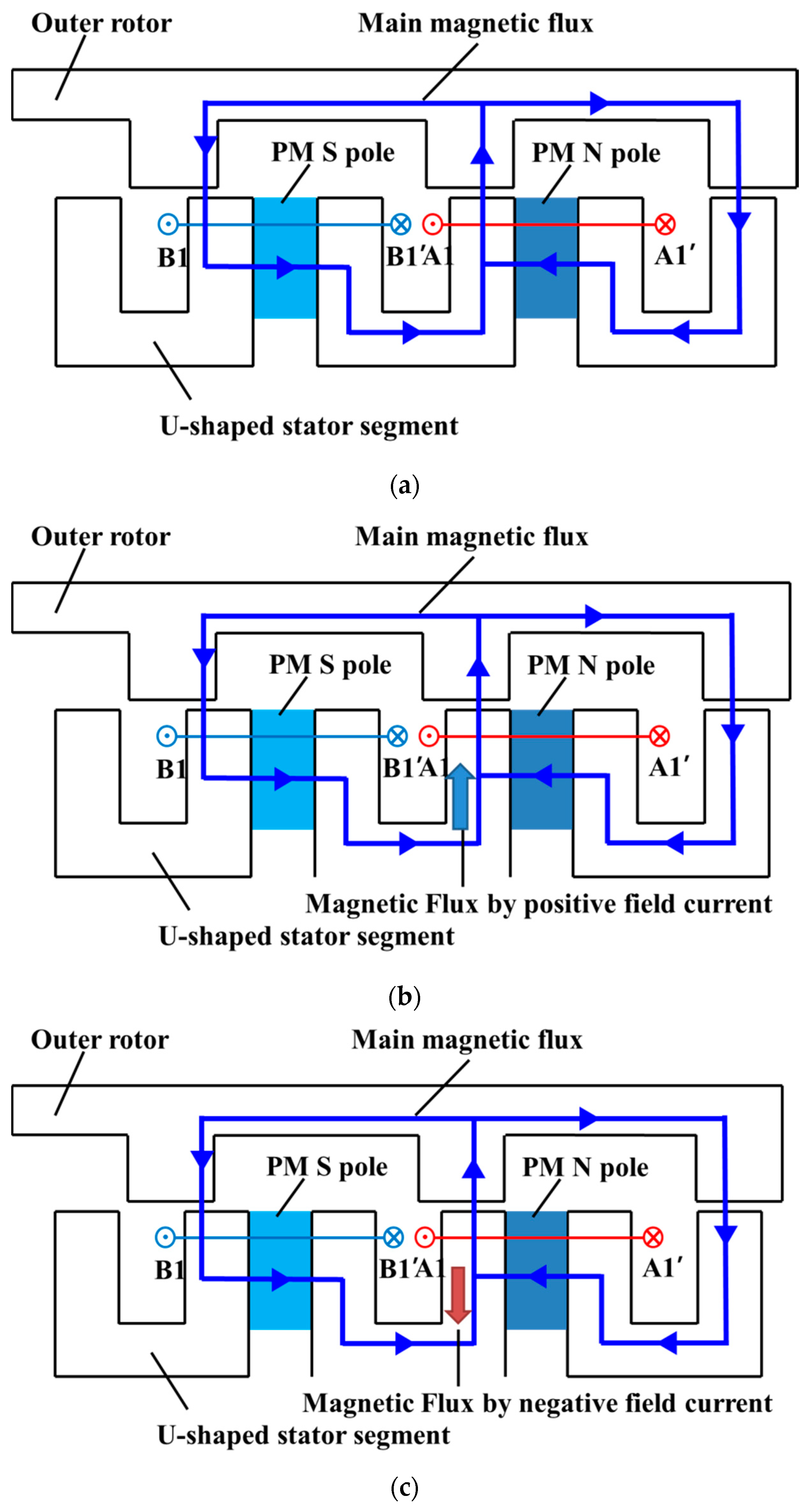
2.2. Operating Principle of the Proposed FSM

In solely PM flux switching machines, as illustrated in Figure 2a, magnetic flux due to the PMs always exists, with constant polarity in the permanent magnets. In Figure 2a, the outer rotor tooth aligns with the right side of a central U-shaped stator segment, A1, and the PM-excited magnetic flux flows from the stator teeth into the rotor. When the outer rotor moves forward, the rotor tooth aligns with the left side of the right stator segment, A1’. This maintains an identical magnitude of the magnetic flux linkage but in the opposite direction, thus representing the flux-switching principle.
Figure 2b,c show the hybrid-excitation topology of the FSM. When the HTS field coil is excited, flux regulating operation is achieved. Figure 2b,c show the magnetic flux direction of the proposed machine under a positive field current and a negative field current. It is clear that the magnetic flux linkage is decreased by the negative field current and that the flux linkage is increased by the positive field current.

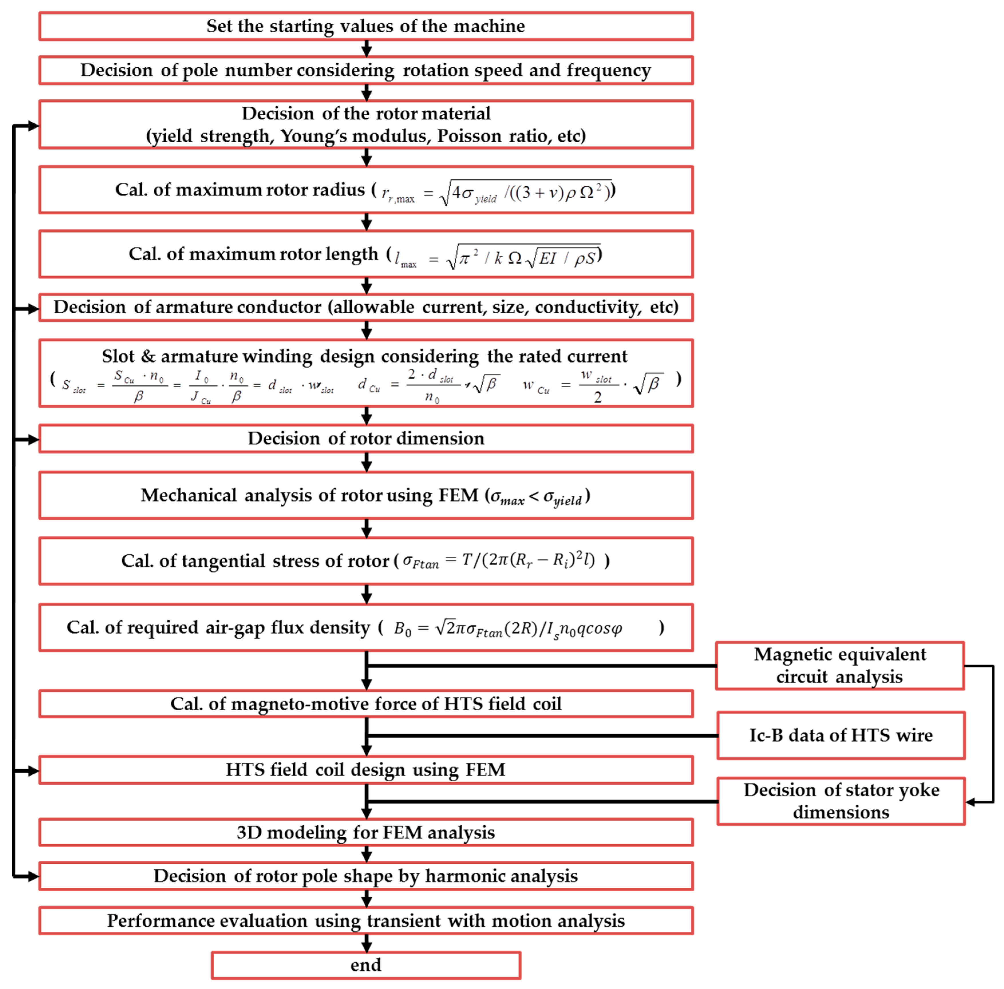
2.3. Design Methodology of the Proposed FSM and HTS Field Coil

Figure 3 presents a flowchart of the design methodology of the proposed hybrid excited flux switching machine (HEFSM) [28,29]. This design process includes the iteration of each step to adjust the slot dimensions and the magneto-motive force (MMF) of the HTS field coil used to achieve the required output power, which is one of the basic specifications. In this design methodology, the parametric design is performed for reducing the number of the iteration of each step. The tangential stress, weight of the rotor, and required air-gap field density according to the rotor dimensions are considered as the parameters.
The tangential stress in the outer rotor is calculated as follows.
σ F t a n = T / ( 2 π ( R r R i ) 2 l )
where, T, Rr, Ri, and l are the torque of the outer rotor by the rated armature current, the rotor outer radius, the rotor inner radius, and the active stack length, respectively. This tangential stress is used to determine the required air-gap field density. As the torque can be expressed as the ratio of the power to the angular velocity Ω, the tangential stress is expressed as follows.
σ F t a n = P / ( ( 2 π ( R r R i ) 2 l ) Ω )
Therefore, the tangential stress value can be calculated by the initial design constraints of the rated output power and rotating speed. In addition, the required air-gap field density, B0, can be calculated by the tangential stress, RMS value of phase current, Is, the number of slots for the armature winding, q, and the power factor.
B 0 = 2 π σ F t a n ( 2 R ) / I s n 0 q c o s φ
The main dimensions of the machine are designed based on the calculated air-gap field density and a finite element analysis (FEA). The FEA is also employed to determine the rest machine parameters and optimize the machine performance. In this study, machines with various rotor pole arc and stator tooth arc are studied to optimize the no-load voltage waveform. The objective of the optimization is to minimize the total harmonic distortion (THD) of the no-load voltage wave form at 1000 rpm. The operating characteristics of the designed machine are analyzed by a transient motion analysis. Based on the design process, the main design specifications of the proposed hybrid excitation FSM are depicted in Table 1.

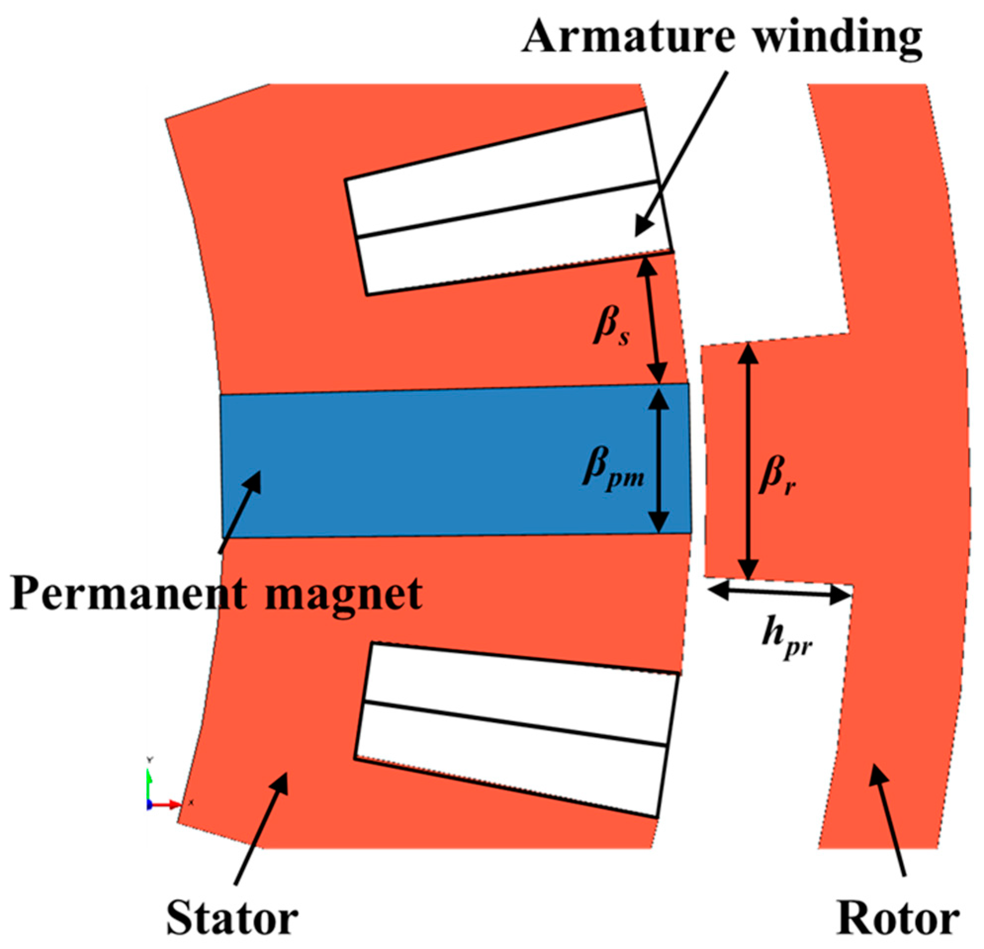
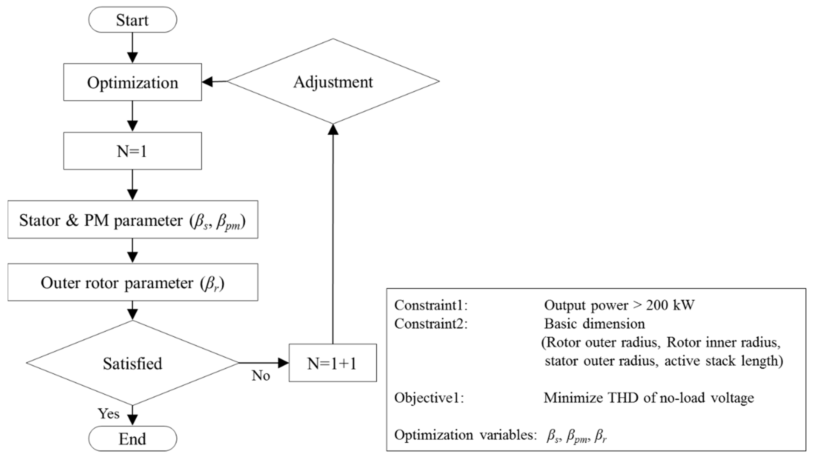
2.4. Machine Design and Optimization

Based on the aforementioned method, an outer-rotor FSM with 18-tooth stator was initially chosen, with the designed values of the basic parameters given in Table 1. The original geometric dimensions were assigned for the initial design and hence are not necessarily optimal. In the initial design, the objective output power and THD of no-load voltage was not accomplished. To improve the THD, design free parameters, βs, βr, and hpr defined in rotor and stator sides, as shown in Figure 4. In this study, the deterministic method is utilized to optimize the machine by adjusting the design free parameters while keeping the air-gap distance and outer rotor radius as shown in Figure 5. The design free parameters are related to the rotor pole shape and stator tooth shape. Based on 3D FEA, the no-load voltage of the machine is simulated from the transient motion analysis. MagNet ver. 7.6 (Mentor, a Siemens Business, Wilsonville, OR, United States), which is commercialized electro-magnetic simulation software, is used for the 3D FEA. The circuit connections of the armature winding are performed by a circuit modeler in the MagNet software. The simulations are carried out by interworking with an electro-magnetic analysis. This simulation allows analysis of the transient and motion behavior of the machine. The phase voltage waveforms of the machine different rotor pole arc width and stator tooth arc width are plotted and their THDs and amplitudes are calculated. The machine with 8 degrees rotor pole arc width and 5 degrees stator tooth arc width generates the no-load voltage with minimum THD value. Furthermore, the output power of the machine increases by approximately 20% by the optimization. Based on the analysis, the machine with 8 degrees rotor pole arc width and 5 degrees stator tooth arc width is chosen as the optimal design in terms of overall output power and THD value of the no-load voltage. The results are given in Table 2, which clearly shows that the output power and voltage wave distortion are improved by adjusting the rotor pole and stator tooth shape.

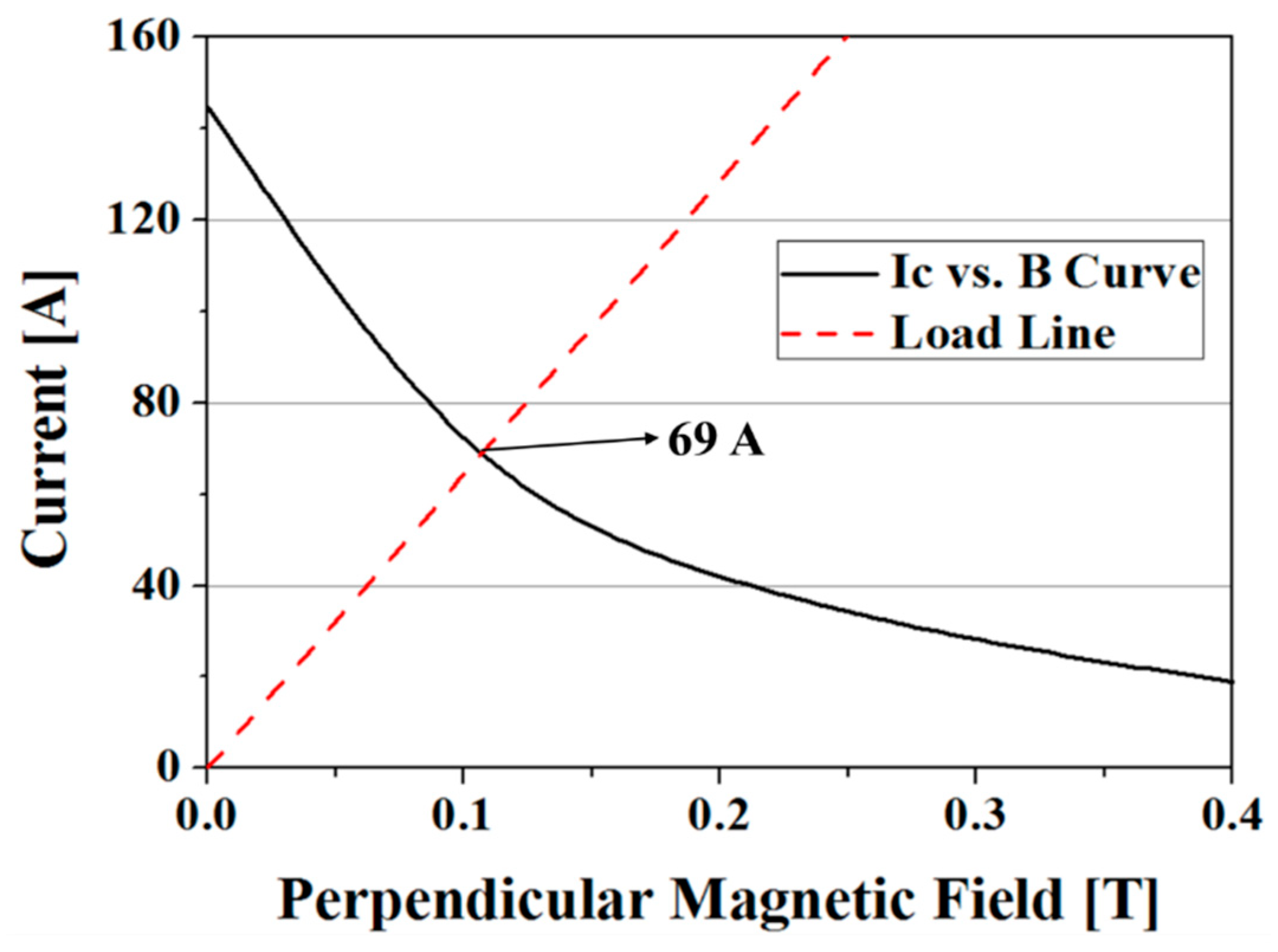
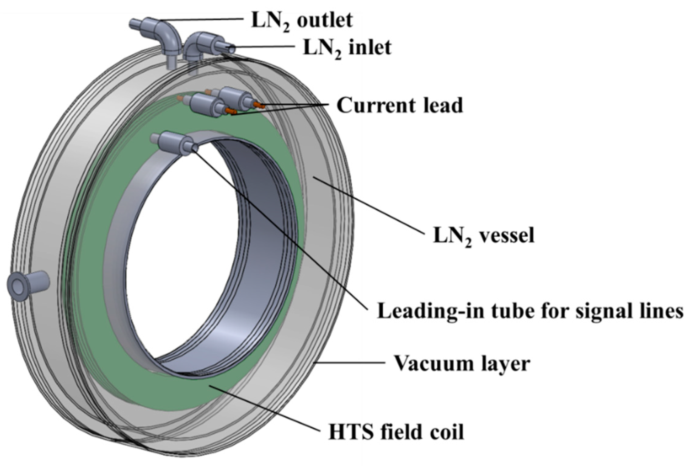
2.5. Design of the HTS Field Coil and Cryostat

The HTS field coil is a significant component of the FSM. Electric machines employing an HTS field coil are associated with a higher magnetic field density levels and a more compact volume compared to electric machines which have a copper coil [30,31,32,33]. The critical current, IC, of the HTS field coil at 77 K can be estimated based on data pertaining to the critical current degradation characteristics according to the external magnetic field of the HTS wire at 77 K [32]. In this study, two series connected double-pancake coils (DPCs) are considered. The double-pancake coils have an outer radius of 170 mm and an inner radius of 130 mm, each with 50 turns per single pancake coil (SPC). The Bi-2223 wire with IC of 145 A at 77 K and self-field characteristics was considered for the HTS field coil. As shown in Figure 6, the IC of the HTS field coil was estimated to be 69 A using a load line [33]. The key parameters of the HTS field coil are summarized in Table 3. Figure 7 depicts the field distribution in the HTS field coil under both a resistive load of 1 Ω and a no-load condition. The maximum value of the magnetic field in the resistive load for the 1 Ω condition is approximately 0.11 T, while that in the no-load condition is approximately 0.13 T, in the load condition, the magnetic field, due to the armature current generated a direction opposite to the original magnetic field. Figure 8 shows the liquid nitrogen (LN2) cryostat designed for the HTS field coil of the proposed FSM. The cryostat is composed of a vessel, current leads for field current excitation, a LN2 inlet, a LN2 outlet, and leading-in tubes. The outer radius, inner radius, and length of the cryostat are 202 mm, 122 mm, and 80 mm, respectively. The cryostat can hold approximately 6.5 liters of LN2. In order to reduce the heat loss, MLI was applied. Table 4 presents the estimation results of the thermal load according to the following equations [34,35].
Q c l = ( ( ρ c l l c l I 2 ) / A c l k c l A c l ( T H T L ) / L c l ) 2 + 2 I ρ c l k c l ( T H T L )
Q K = N l A l k l ( T H T L ) / L l
Q r = σ ( T H 4 T L 4 ) / ( ( 1 ε H ) / ε H A H + ( 1 / ε L + 2 N / ε N N ) / A L )
where, Qcl, QK, and Qr are the thermal loads from the conduction heat transfer due to the pair of current leads, the conduction heat transfer due to the signal lines (or leading-in tubes), and the radiation heat transfer of the vessel. The total heat loss was estimated to be approximately 14.13 W when three layers of MLI were applied outside of the vessel. Because the latent heat of the vaporization of liquid nitrogen is 199.2 J·s−1, the liquid nitrogen in the cryostat will evaporate within 200 min by boil-off, due to the thermal load. Therefore, for the long-term operation of the HTS field coil, a forced circulation cooling method for the circulation of the refrigerant must be considered in the future [36,37].

3. Characteristic Analysis of the Proposed FSM

3.1. Characteristics Analysis Method Using FEM Software

In this study, FEM software was used to analyze the operating characteristics of the designed FSM. MagNet is electro-magnetic simulation software which is used for the design and analysis of electrical machinery or any component with PMs or coils. Because the proposed FSM has a homopolar structure, its performance was analyzed by a 3D FEA method. For this analysis, the circuit connection of the armature windings was determined using a circuit modeler in the MagNet program. Simulations were carried out by interworking with an electro-magnetic analysis. Table 5 shows the magnetic properties of the Nd-Fe-B material used for the simulations of the FSM.

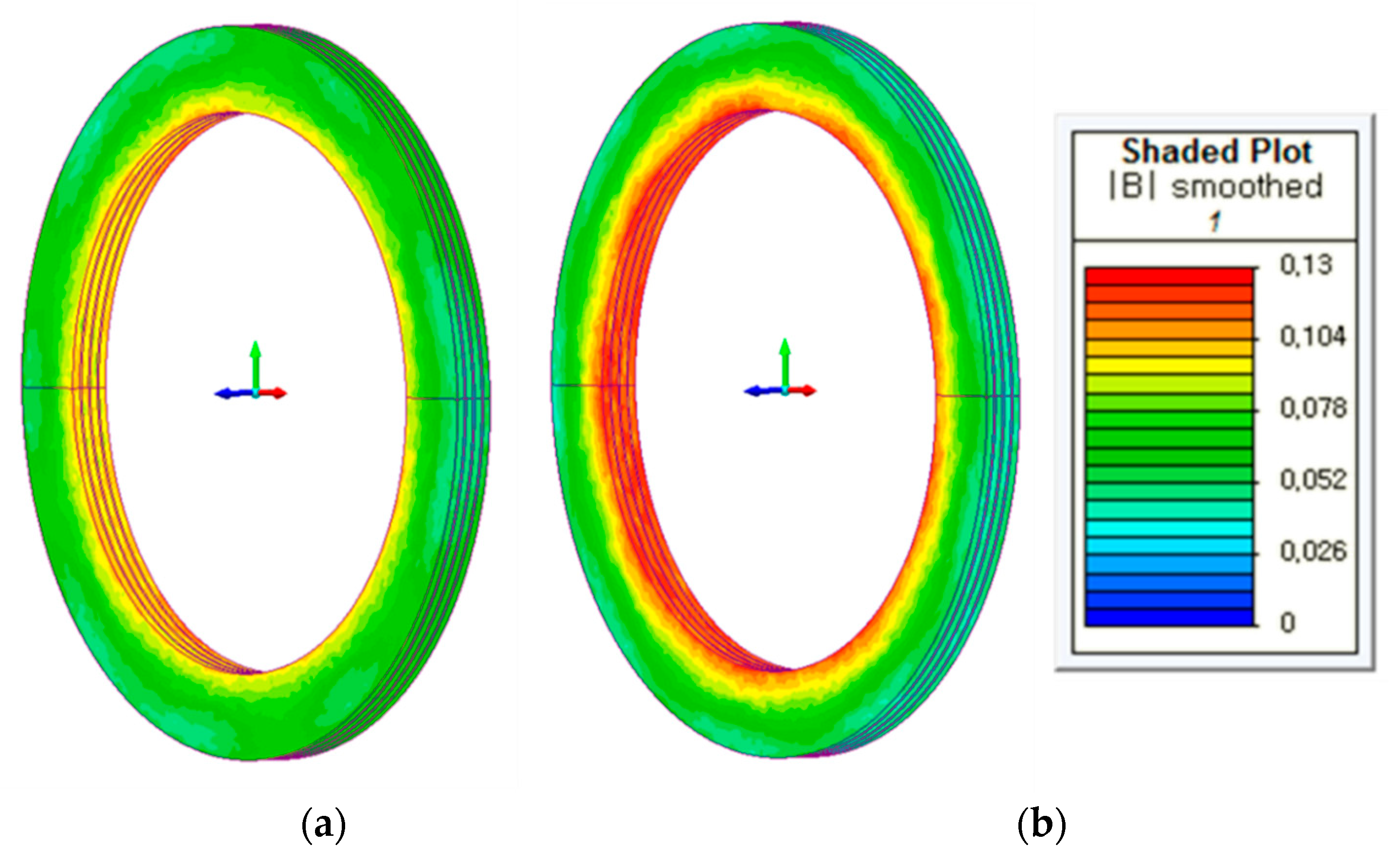
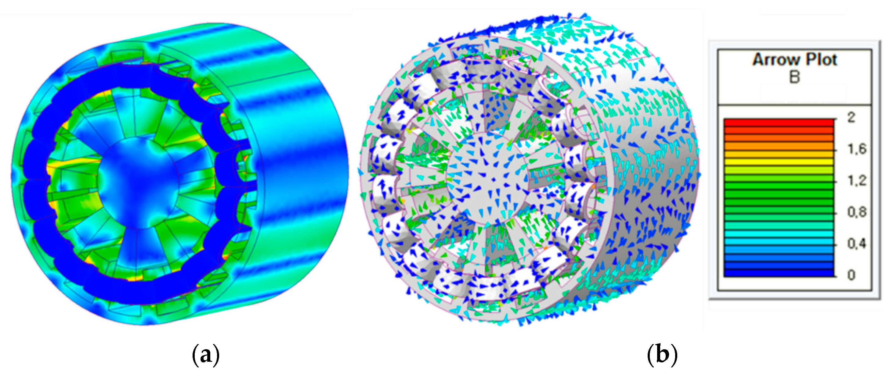
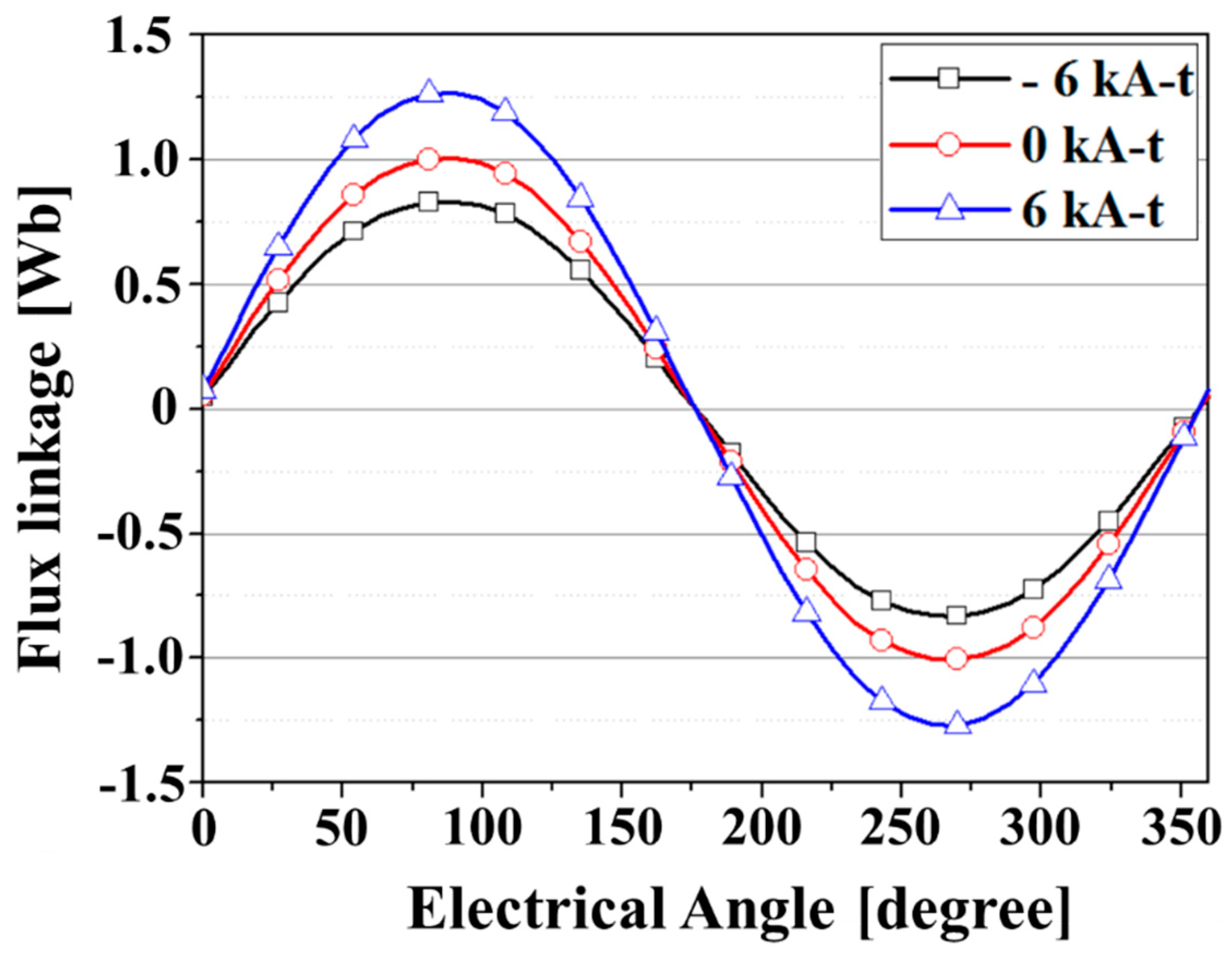
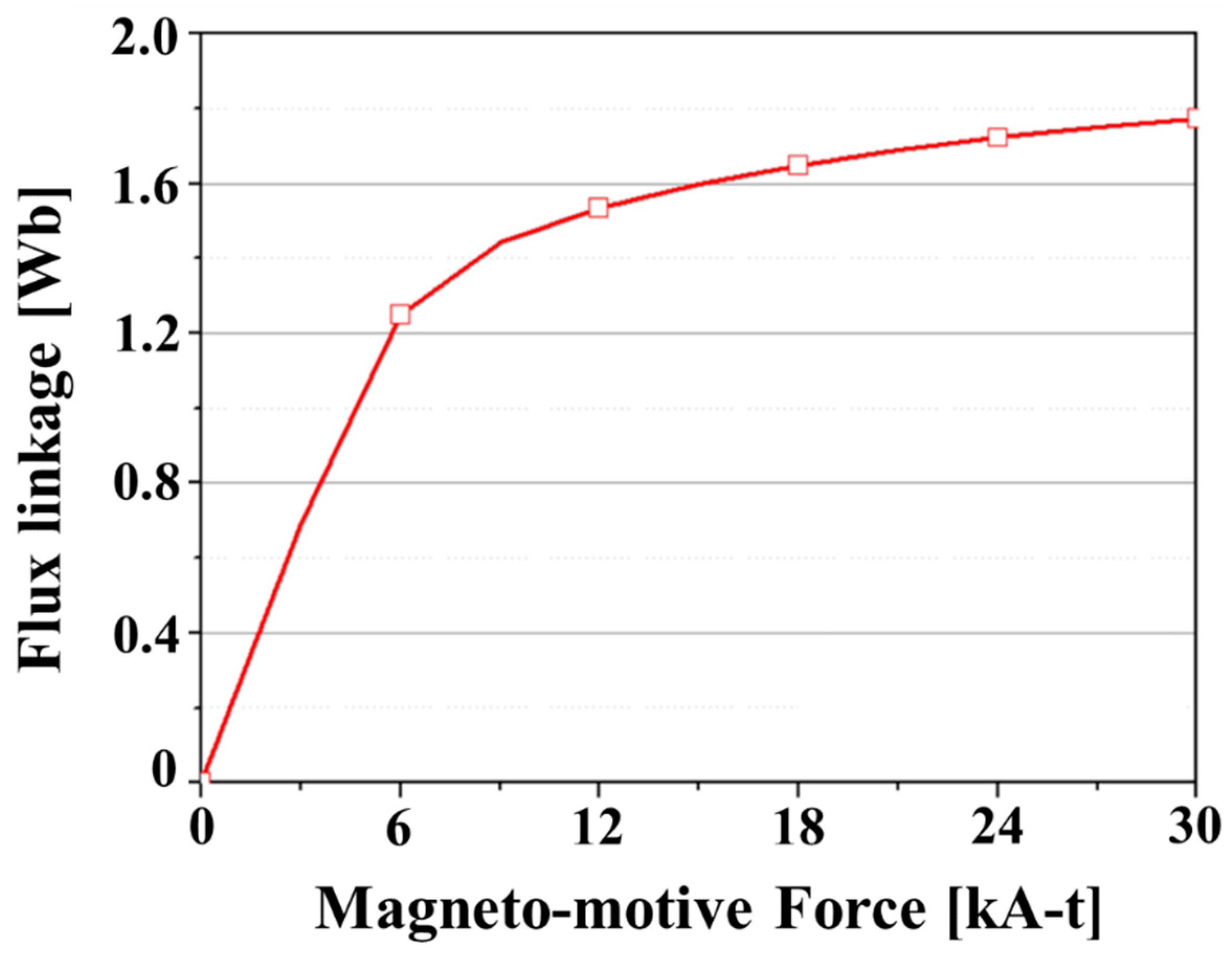
3.2. Field Distribution of the Proposed FSM

In the no-load condition, the magnetic field distributions of the machine in different operation modes were analyzed. Figure 9 presents the magnetic field distributions generated by the PM and positive field current. Figure 10 shows the flux linkage in different operation modes. By adjusting the field current, the flux linkage can be regulated. Figure 11 shows the flux linkage in the phase A armature according to the MMF of the HTS field coil. The flux linkage increases due to the positive field current. In the positive hybrid excitation mode, the amplitudes of the flux linkage increase linearly with the MMF of the HTS field coils when it is below 6 kA∙t. However, those at an MMF above 6 kA∙t are highly saturated, indicating that an appropriate decision of the field current is required in order to minimize the electrical losses in the desired output [33]. Therefore, in this study, the operating characteristics of the machine are investigated by setting the maximum operating MMF to 6 kA∙t.

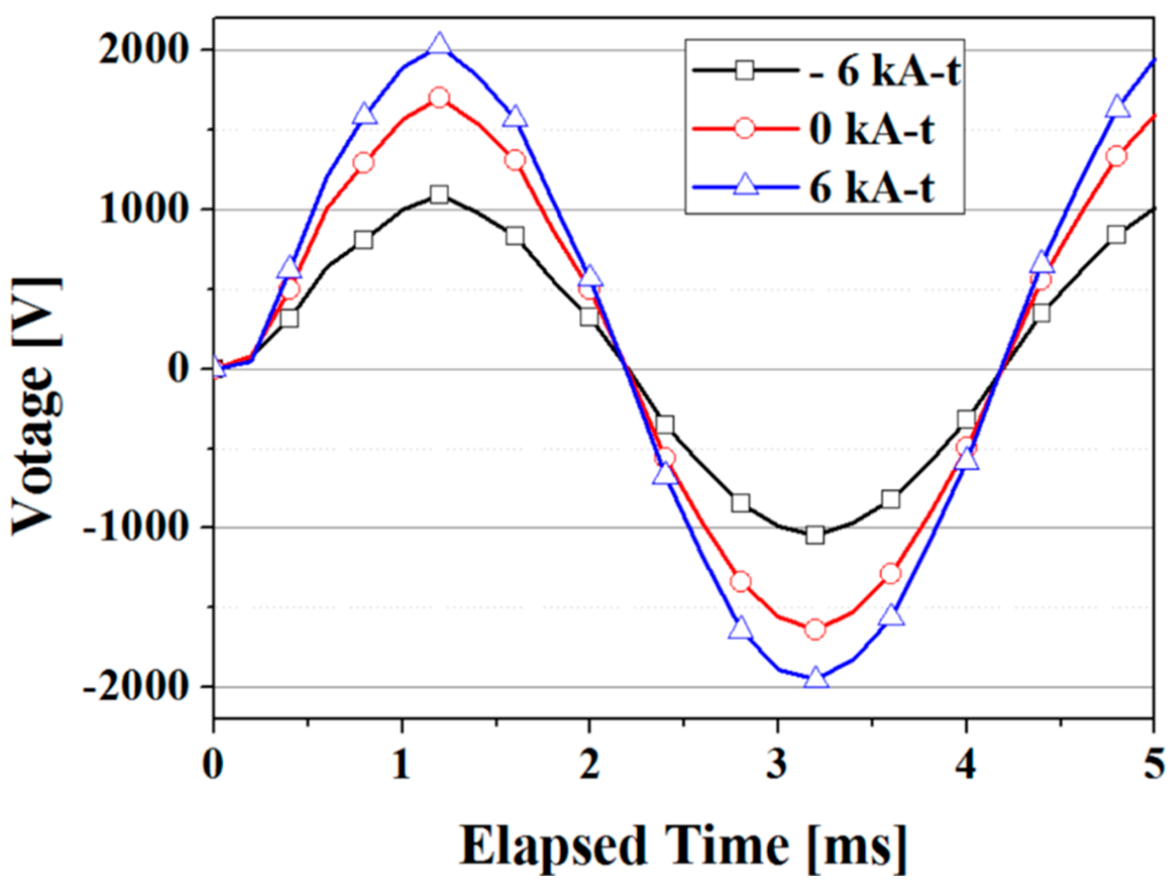
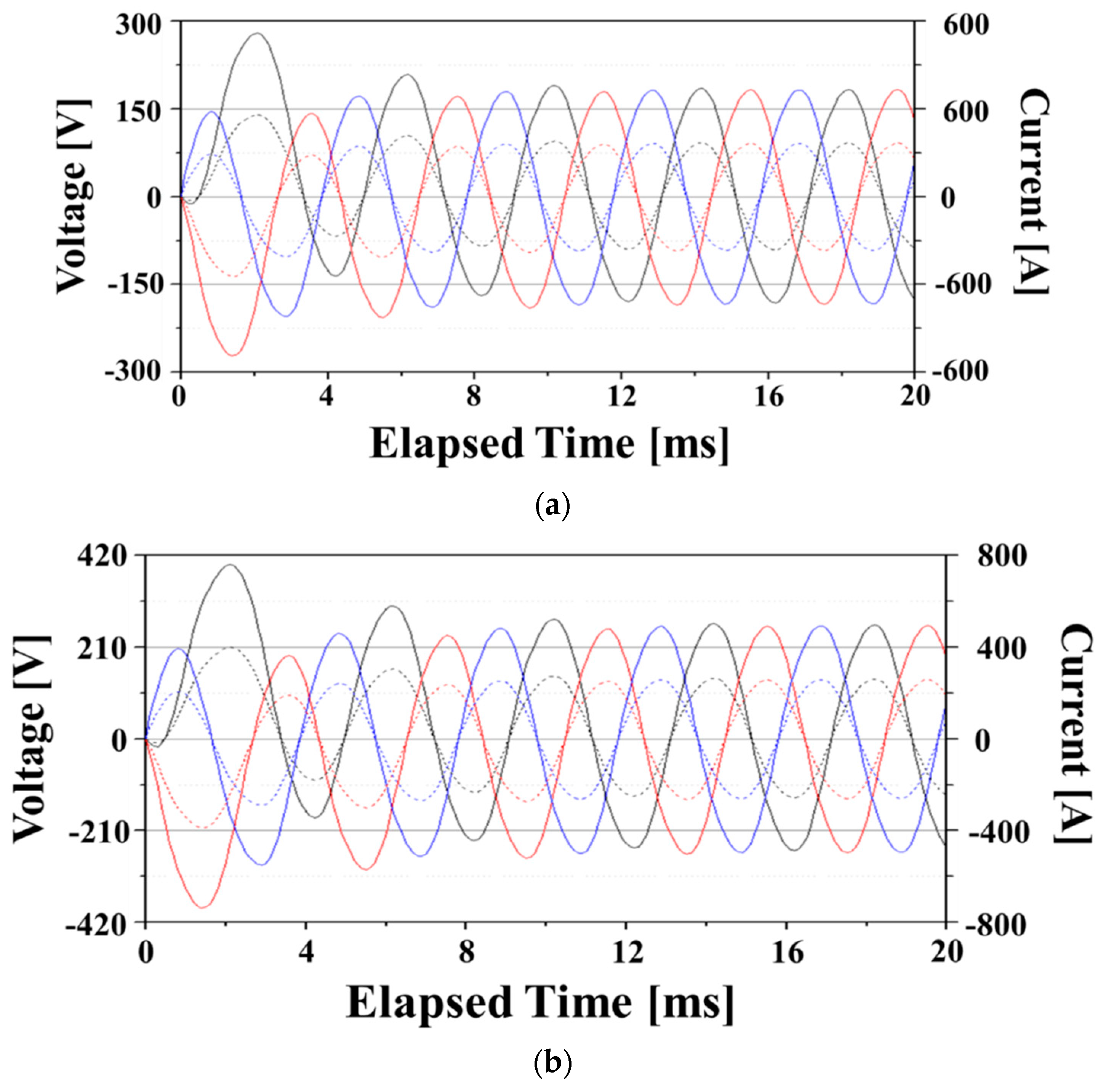
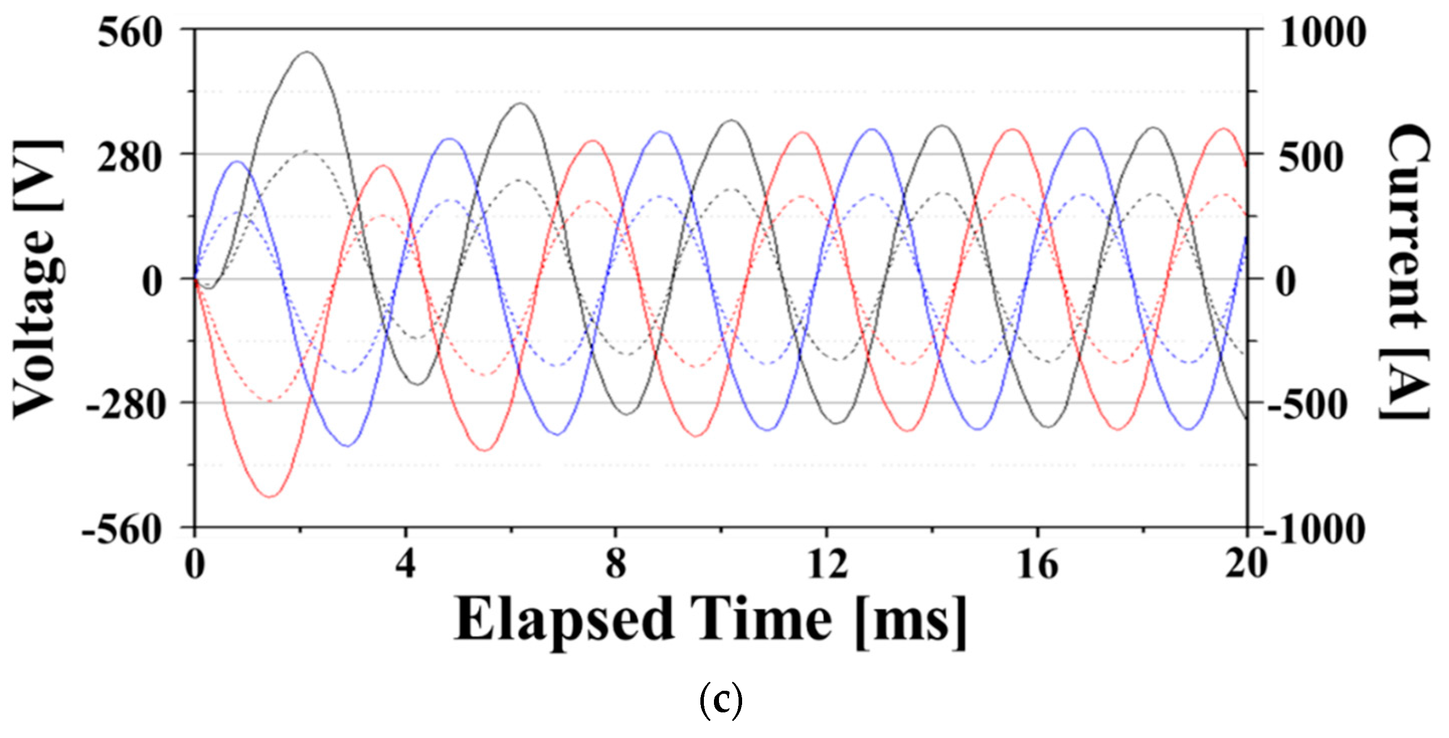
3.3. Transient Motion Analysis of the Proposed FSM

Figure 12 compares the no-load voltages under different excitation modes at 1000 rpm. For the case with solely the PM excitation mode, the peak value of the no-load voltage is approximately 1.75 kV. The peak values in the positive excitation mode and the negative excitation mode at 6 kA∙t are 2.03 and 1.09 kV, respectively. By applying an MMF of 6 kA∙t, the no-load voltage was increased by nearly 16%, from 1.75 V to 2.03 V. By applying an MMF of −6 kA∙t, the no-load voltage was reduced by 62%, from 1.75 V to 1.09 V.
Figure 13 shows the phase voltage and line current waveforms at the rated operation condition. These simulations were performed to investigate the output power variation characteristics according to flux regulation in the generator mode. To do this, the armature winding coils were connected to a resistive load of 1 Ω. In this simulation, given that current source for the HTS field coil operates from the first 0 second, the output value differs for each phase up to about 11 ms due to the transient response (step response) component. It could be confirmed that the output power of the positive excited FSM is approximately 200 kW. On the other hand, in the negative excitation mode, the output power of the FSM is approximately 59 kW, showing a reduction of 49% compared to that in the solely PM excitation mode.
The HTS field coil can generate a high magnetic field, and flux regulation capability of the machine applying the HTS field coil can be improved. However, superconductors are subject to loss under time-varying magnetic field or time-varying current conditions due to their magnetic hysteresis characteristics. Therefore, when the HTS field coil is charged and discharged, a loss occurs in the HTS field coil. This may affect the flux-regulation effectiveness of the machine. In this study, the losses in the designed HTS field coil were calculated by the following equations [38,39].
Q = ( 13 B a 3.6 0.38 B a ) / ( 13 B a 3.6 + 0.38 B a ) + 6 10 11 I t 3.6 + 1.5 10 5 B a I t 2
Q = ( 3.25 B a 3.6 0.034 B a ) / ( 3.25 B a 3.6 + 0.034 B a ) + 6 10 11 I t 3.6 + 7.5 10 7 B a I t 2
where Ba means the maximum value of the time-varying magnetic field and It is the excitation current level of the HTS field coil fabricated by Bi-2223 wire. Q and Q represents the loss generated by the perpendicular component and the parallel component of the external magnetic field, respectively. Figure 14 shows the calculation results for the loss of the HTS field coil according to the MMF. In the graph, the cycle in the unit of loss (Joule/cycle) means one sequence in which the field current is charged and discharged. For the case with solely the PM excitation mode, the loss generated in the HTS field coil is approximately 3.14 μJ/cycle. The loss in the positive excitation mode and the negative excitation mode at 6 kA∙t are 912.1 mJ/cycle and 923.3 mJ/cycle, respectively. Although the losses increase as the MMF of the HTS field coil increases, the magnitude is much smaller than the output power of the proposed machine. This means that the trade-off relationship between the flux-regulation capability and the loss of the HTS field coil does not need to be considered significantly within the designed field current level.
A typical outer-rotor FSM was simulated to compare with the proposed generator employing HTS homopolar topology. Figure 15 shows a 3D model of the typical outer-rotor PM FSM without HTS field coil. The main parameters compared with the typical generator are shown in Table 6. Since the proposed generator has homopolar iron-core and HTS coil for flux regulation, the weight and iron loss of the generator are larger than that of the typical generator. However, as shown in Table 6, it has the advantage that the output can be adjusted by flux control.

3.4. Perfomance Comparisons of the Proposed FSM with Other Outer-Rotor Brushless Machines [35,36]

In this section, the performances of the proposed hybrid excitation flux-switching machine (HEFSM) are compared with those of other outer-rotor brushless machines, such as permanent magnet Vernier machine (PMVM), permanent magnet flux-switching machine (PMFSM), and high temperature superconducting Vernier machine (HTSVM) [40,41]. By comparing the performance of the four machines, it is shown that the proposed HEFSM has excellent characteristics in terms of output power density and flux controllability, so it is more suitable for variable-speed rotating machine applications, such as electric propulsion and wind turbines. The parameters of performance are represented in Table 7.

4. Conclusions

In this paper, a novel topology of a hybrid excitation flux-switching machine for variable-speed synchronous machine applications has been proposed. This topology makes the outer-rotor flux-switching machine more attractive due to the improved flux-regulation capability. The proposed machine adopts a stator hybrid excitation topology with the integration of the PMs and the HTS field coil together. The proposed structure, operating principle, and a characteristic analysis by the FEM are presented and discussed. By adjusting the field current in the HTS field coil, the flux linkage can be regulated. This paper is mainly concerned with a feasibility validation of a hybrid excitation topology with an outer-rotor structure employing a homopolar iron-core. The proposed topology is applicable to areas such as electric propulsion systems and wind power generation systems, which require robust machine structures and excellent flux regulation capabilities. However, because HTS field coils are applied, a reliable cooling system and a quench protection system for the HTS field coils should be studied in future research for realization of this machine. This paper is expected to provide good references for further research, including work on prototype manufacturing.

Author Contributions

All authors contributed to this work by collaboration. Y.J.H. designed the whole structure of the paper and performed the simulations; J.M.K. and J.C. proposed the new topology and wrote the first draft; J.Y.J. performed data analysis.

Funding

This work was supported by the Korea Basic Science Institute under Grant D39611.

Conflicts of Interest

The authors declare no conflict of interest.

Nomenclature

HTShigh-temperature superconductor
FSMflux switching machine
MMFmagneto-motive force
DPCdouble-pancake coil
SPCsingle-pancake coil
MLImulti-layer insulation
FEMfinite element method
ρclelectrical resistivity of the current lead
lcllength of the current lead
Itransport current through the current lead
Aclcross-sectional area of the current lead
kclthermal conductivity of the current lead
THtemperature at the high-temperature part
TLtemperature at the low-temperature part
NlNo. of signal lines or leading-in tubes
Alcross-sectional area of a signal line or a leading-in tube
klthermal conductivity of a signal line or a leading-in tube
Lllength of a signal line or a leading-in tube
σStefan-Boltzmann constant (5.67 × 10⁻⁸ W·m-2·K-4)
εHemissivity of the vessel
εNemissivity of MLI
NNo. of MLI
AHsurface area of the high-temperature part
ALsurface area of the low-temperature part

References

  1. Lee, C.H.T.; Chau, K.T.; Liu, C.; Lin, F. Design and Analysis of a Magnetless Flux-Switching DC-Excited Machine for Wind Power Generation. J. Int. Counc. Electr. Eng. 2014, 4, 80–87. [Google Scholar] [CrossRef] [Green Version]
  2. Pellegrino, G.; Vagati, A.; Guglielmi, P.; Boazzo, B. Performance comparison between surface-mounted and interior PM motor drives for electric vehicle application. IEEE Trans. Ind. Electron. 2012, 59, 803–811. [Google Scholar] [CrossRef]
  3. Pellegrino, G.; Armando, E.; Guglielmi, P. Direct-flux vector control of IPM motor drives in the maximum torque per voltage speed range. IEEE Trans. Ind. Electron. 2012, 59, 3780–3788. [Google Scholar] [CrossRef]
  4. Gieras, J.F. Permanent Magnet Motors Technology: Design and Applications, 3rd ed.; CRC Press Taylor & Francis Group: New York, NY, USA, 2010. [Google Scholar]
  5. Morimoto, S.; Takeda, Y.; Hirasa, T.; Taniguchi, K. Expansion of operating limits for permanent magnet motor by current vector control considering inverter capacity. IEEE Trans. Ind. Appl. 1990, 26, 866–871. [Google Scholar] [CrossRef]
  6. Le, W.; Ching, T.W.; Chau, K.T. Design and Analysis of an Outer-Rotor Parallel-Hybrid-Excited Vernier Machine. Chin. J. Electr. Eng. 2017, 3, 27–32. [Google Scholar]
  7. Hoang, E.; Lecrivain, M.; Gabsi, M. A new structure of a switching flux synchronous polyphased machine with hybrid excitations. In Proceedings of the 2007 European Conference on Power Electronics and Applications, Aalborg, Denmark, 2–5 September 2007; pp. 1–8. [Google Scholar]
  8. Hua, W.; Cheng, M.; Zhang, G. A novel hybrid-excitation flux switching motor for hybrid vehicles. IEEE Trans. Magn. 2009, 45, 4728–4731. [Google Scholar] [CrossRef]
  9. Zhang, C.; Hua, W.; Cheng, M.; Liao, J.; Wang, K.; Zhang, J. Investigation of an Improved Hybrid-Excitation Flux-Switching Brushless Machine. IEEE Trans. Ind. Appl. 2015, 51, 3791–3799. [Google Scholar] [CrossRef]
  10. Gaussens, B.; Hoang, E.; Lécrivain, M.; Manfe, P.; Gabsi, M. A hybrid-excited flux-switching machine for high-speed DC-alternator applications. IEEE Trans. Ind. Electron. 2014, 61, 2076–2989. [Google Scholar] [CrossRef]
  11. Rahimi, S.K.; Sulaiman, E. Design investigation of hybrid excitation flux switching machine for high-speed electric vehicles. In Proceedings of the 2014 IEEE 8th International Power Engineering and Optimization Conference (PEOCO2014), Langkawi, Malaysia, 24–25 March 2014; pp. 303–307. [Google Scholar]
  12. Zhang, G.; Cheng, M.; Hua, W.; Dong, J.N. Analysis of the oversaturated effect in hybrid excited flux-switching machines. IEEE Trans. Magn. 2011, 47, 2827–2830. [Google Scholar] [CrossRef]
  13. Hua, W.; Cheng, M.; Zhang, G. Electromagnetic performance analysis of hybrid-excited flux-switching machines by a nonlinear magnetic network model. IEEE Trans. Magn. 2011, 47, 3216–3219. [Google Scholar] [CrossRef]
  14. Xu, W.; Zhu, J.; Zhang, Y.; Guo, Y.; Lei, G. New axial laminated structure flux-switching permanent magnet machine with 6/7 poles. IEEE Trans. Magn. 2011, 47, 2823–2826. [Google Scholar] [CrossRef]
  15. Rauch, S.E.; Johnson, L.J. Design principles of flux-switching alternators. AIEE Trans. Power App. Syst. 1995, 74, 1261–1268. [Google Scholar]
  16. Zhu, Z.Q.; Chen, J.T. Advanced flux-switching permanent magnet brushless machines. IEEE Trans. Magn. 2010, 46, 1447–1453. [Google Scholar] [CrossRef]
  17. Hoang, E.; Ben-Ahmed, A.H.; Lucidarme, J. Switching flux permanent magnet polyphased synchronous machines. In Proceedings of the 7th European Conference on Power Electronics and Applications, Trondheim, Norway, 8–10 September 1997; pp. 903–908. [Google Scholar]
  18. Zhu, Z.Q.; Howe, D. Electrical machines and drives for electric, hybrid, and fuel cell vehicles. Proc. IEEE 2007, 95, 746–765. [Google Scholar] [CrossRef]
  19. Kim, J.M.; Jang, J.Y.; Lee, S.-G.; Hwang, Y.J. Characteristics Analysis of an HTS Flux-Switching Synchronous Generator with NI-Type HTS Field Coils. IEEE Trans. Appl. Supercond. 2018, 28, 5202705. [Google Scholar] [CrossRef]
  20. Li, W.; Chau, K.T.; Ching, T.W.; Wang, Y.; Chen, M. Design of a High-Speed Superconducting Bearlingless Machine for Flywheel Energy Storage Systems. IEEE Trans. Appl. Supercond. 2015, 25, 5700204. [Google Scholar]
  21. Lee, S.-H.; Hong, J.-P.; Kwon, Y.-K.; Jo, Y.-S.; Baik, S.-K. Study on Homopolar Superconductivity Synchronous Motors for Ship Propulsion Applications. IEEE Trans. Appl. Supercond. 2008, 18, 717–720. [Google Scholar]
  22. Sivasubramaniam, K.; Zhang, T.; Lokhandwalla, M.; Laskaris, E.T.; Bray, J.W.; Gerstler, B.; Shah, M.R.; Alexander, J.P. Development of a High Speed HTS Generator for Airborne Applications. IEEE Trans. Appl. Supercond. 2009, 19, 1656–1661. [Google Scholar] [CrossRef]
  23. Nasr, A.; Hlioui, S.; Gabsi, M.; Mairie, M.; Lalevee, D. Design Optimization of a Hybrid-Excited Flux-Switching Machine for Aircraft Safe DC Power Generation Using a Diode Bridge Rectifier. IEEE Trans. Ind. Elect. 2017, 64, 9896–9904. [Google Scholar] [CrossRef]
  24. Farrok, O.; Islam, M.R.; Guo, Y.; Zhu, J.; Xu, W. A Novel Design Procedure for Designing Linear Generators. IEEE Trans. Ind. Elect. 2018, 65, 1846–1854. [Google Scholar] [CrossRef]
  25. Farrok, O.; Islam, M.R.; Sheikh, M.R.I.; Xu, W. A new optimization methodology of the linear generator for wave energy conversion systems. In Proceedings of the IEEE International Conference on Industrial Technology (ICIT2016), Taipei, Taiwan, 14–17 March 2016; pp. 1412–1417. [Google Scholar]
  26. Fei, W.; Luk, P.C.; Shen, J.X.; Wang, Y.; Jin, M.J. A Novel Permanent Magnet Flux Switching Machine with an Outer-Rotor Configuration for In-Wheel Light Traction Applications. IEEE Trans. Ind. Appl. 2012, 48, 1496–1506. [Google Scholar] [CrossRef]
  27. Kumar, R.; Sulaiman, E.; Jenal, M.; Bahrim, F.S. Parametric Optimization and Performance Analysis of Outer Rotor Permanent Magnet Flux Switching Machine for Downhole Application. J. Magn. 2017, 22, 69–77. [Google Scholar] [CrossRef] [Green Version]
  28. Hwang, Y.J.; Ahn, M.C.; Lee, J.; Yoon, Y.S.; Kim, H.M.; Chung, Y.D.; Jo, Y.-S.; Kim, T.J.; Ko, T.K. Electromagnetic design of a 15 MW-class HTS flux switching synchronous machine considering mechanical stress of the rotor core. IEEE Trans. Appl. Supercond. 2014, 24, 5202305. [Google Scholar]
  29. Pooke, D.M.; Chamritski, V.; Gibson, S.; Staines, M.P.; Fee, M.; Buckley, R.G. A versatile laboratory electromagnet with HTS coils. IEEE Trans. Appl. Supercond. 2004, 14, 1202–1205. [Google Scholar] [CrossRef]
  30. Hwang, Y.J.; Jang, J.Y.; Park, S.-Y.; Choi, Y.S. Feasibility Study of a Multipole Electromagnet Using a Parallel Iron-Core Structure. IEEE Trans. Appl. Supercond. 2018, 28, 4902005. [Google Scholar] [CrossRef]
  31. Kang, M.; Koo, M.; Lee, H.; Cha, G. Current estimation of an HTS BSCCO magnet having multiple power sources based on the field dependent E-J relation. IEEE Trans. Appl. Supercond. 2009, 19, 1257–1261. [Google Scholar] [CrossRef]
  32. Jo, H.C.; Choi, S.; Na, J.B.; Jang, J.Y.; Hwang, Y.J.; Kim, H.J.; Ahn, M.C.; Chung, Y.D.; Kim, H.M.; Ryu, K.-S.; et al. Characteristics comparison for the various winding methods of HTS magnets. IEEE Trans. Appl. Supercond. 2012, 22, 4902907. [Google Scholar]
  33. Sulaiman, E.; Khan, F.; Kosaka, T. Field-Excited Flux Switching Motor Design, Optimization and Analysis for Future Hybrid Electric Vehicle Using Finite Element Analysis. Prog. Electromagn. Res. B 2016, 71, 153–166. [Google Scholar] [CrossRef]
  34. Incropera, F.P.; Dewitt, D.P. Fundamentals of Heat and Mass Transfer; John Wiley & Sons: New York, NY, USA, 1996. [Google Scholar]
  35. Kim, M.S.; Choi, Y.S.; Kim, D.L. Variable Temperature Cryostat for Cryogenic Temperature Sensor Calibration. Supercond. Cryog. 2012, 14, 46–49. [Google Scholar] [CrossRef]
  36. Moon, H.; Kim, Y.-C.; Park, H.-J.; Park, M.; Yu, I.-K. Development of a MW-Class 2G HTS Ship Propulsion Motor. IEEE Trans. Appl. Supercond. 2016, 26, 5203805. [Google Scholar] [CrossRef]
  37. Maguire, J.F.; Winn, P.M.; Sidi-Yekhlef, A.; Yuan, J. Cooling System for HTS Machine. U.S. Patent 6 347 522 B1, 19 February 2002. [Google Scholar]
  38. Kim, Y.H.; Jang, J.Y.; Jo, H.C.; Choi, S.; Na, J.B.; Lee, C.Y.; Song, J.-B.; Lee, H.; Ko, T.K.; Hwang, Y.J. A Study on the Loss in a Superconducting Magnet by the Control Current in a Hybrid Electro-Magnetic Suspension System. IEEE Trans. Appl. Supercond. 2012, 22, 3600105. [Google Scholar] [CrossRef]
  39. Rabbers, J.J.; Haken, B.T.; Shevchenko, O.A.; ten Kate, H.H.J. An Engineering Formula to Describe the AC Loss of BSCCO/Ag Tape. IEEE Trans. Appl. Supercond. 2001, 11, 2623–2626. [Google Scholar] [CrossRef]
  40. Yao, Y.; Liu, C.; Lee, C.H.T. Quantitative Comparisons of Six-Phase Outer-Rotor Permanent-Magnet Brushless Machines for Electric Vehicles. Energies 2018, 11, 2141. [Google Scholar] [CrossRef]
  41. Li, W.; Ching, T.W.; Chau, K.T.; Lee, C.H.T. A Superconducting Vernier Motor for Electric Ship Propulsion. IEEE Trans. Appl. Supercond. 2018, 28, 5201706. [Google Scholar] [CrossRef]
Figure 1. 3D structure of the proposed flux-switching machine (FSM): (a) main components, and (b) assembly structure.
Energies 12 02654 g001
Figure 2. Operating principle: (a) main magnetic flux by the permanent magnets (PMs), (b) magnetic flux by the positive field current, and (c) magnetic flux by the negative field current.
Energies 12 02654 g002
Figure 3. Flowchart of the design process.
Energies 12 02654 g003
Figure 4. Design parameters of the proposed machine.
Energies 12 02654 g004
Figure 5. Work-flow diagram for machine optimization.
Energies 12 02654 g005
Figure 6. Critical current estimation of the HTS field coil.
Energies 12 02654 g006
Figure 7. Magnetic field distribution in the HTS field coil: (a) resistive load in the 1 Ω condition, and (b) no-load condition.
Energies 12 02654 g007
Figure 8. Liquid nitrogen (LN2) cryostat for the HTS field coil.
Energies 12 02654 g008
Figure 9. (a) Magnetic field distribution and (b) magnetic flux direction in the positive hybrid excitation mode.
Energies 12 02654 g009
Figure 10. Flux linkage wave form with different operation modes.
Energies 12 02654 g010
Figure 11. Flux linkage according to the magneto-motive force (MMF) of the HT field coil.
Energies 12 02654 g011
Figure 12. No-load voltage waveform in the phase A armature winding.
Energies 12 02654 g012
Figure 13. Line current and phase voltage of the resistive load in the 1 Ω condition: (a) −6 kA-t, (b) 0 kA-t, and (c) 6 kA-t.
Energies 12 02654 g013aEnergies 12 02654 g013b
Figure 14. Loss in the HTS field coil according to the magneto-motive force.
Energies 12 02654 g014
Figure 15. 3D structure of the typical outer-rotor flux-switching generator.
Energies 12 02654 g015
Table 1. Basic design specifications of initial machine.
ParametersValue
No. of stator slot18 mm
No. of rotor pole15 mm
Rotor outer radius370 mm
Rotor inner radius318 mm
Stator outer radius315 mm
Active stack length480 mm
Air gap distance3 mm
Permanent magnet arc width, βpm3.3°
Rotor pole arc width, βr3.3°
Stator tooth arc width, βs3.3°
Rated rotating speed1000 rpm
Phases3
Table 2. Overall comparisons of initial and optimized design.
MachinesPermanent
Arc Width
Rotor Pole Arc WidthStator Tooth Arc WidthTHD of No-Load VoltageOutput Power
Initial design3.3°3.3°3.3°11.2%167.2 kW
Optimal design3.1%200.4 kW
Table 3. Key design parameters of the HTS field coil.
ItemValue
HTS wireBi-2223 wire
Winding structureDouble pancake coil × 2EA
Inner radius130 mm
Outer radius170 mm
No. of turns per SPC50
Total winding turns200
Operating temperature77 K
Estimated Ic @ 77K69 A
Table 4. Thermal loads of the LN2 cryostat.
ParameterValue
Conductive Heat LossCurrent Lead2.926 [W]
Signal Line0.045 [W]
Leading-in Tube7.602 [W]
Radiation Heat LossVessel Wall3.557 [W]
Table 5. Magnetic properties of the Nd-Fe-B at 20 K.
ItemValue
Relative permeability1.06015
Coercivity−813,242 A/m
Residual induction Br1.08 T
Table 6. Main parameter comparison.
ParameterProposed FSMTypical PMFSM
Output power59–200 kW (Controllable)120 kW
Mass134 kg94.5 kg
Core loss in solely PM excitation mode55.7 W48.3 W
Table 7. Machine performance comparisons.
ParameterPMVMPMFSMHTSVMHEFSM
Efficiency92.89%86.73%87.86%
Base speed600 rpm1000 rpm230 rpm1000 rpm
Output power13.68 kW13.69 kW1000 kW200.4 kW
Power density3.6 MW/m33.6 MW/m3168 kW/m33.9 MW/m3
Outer rotor diameter220 mm220 mm3200 mm370 mm
Stack length100 mm100 mm740 mm480 mm
Field excitationPMPMHTSPM + HTS
Flux controllabilityxxcontrollablecontrollable

