Article

Characteristic Analysis of the Peak Braking Force and the Critical Speed of Eddy Current Braking in a High-Speed Maglev

1
College of Electrical Engineering, Qingdao University, Qingdao 266071, China
2
National Key Laboratory of Science and Technology on Vessel Integrated Power System, Naval University of Engineering, Wuhan 430032, China
3
Department of Electrical and Electronic Engineering, University of Bristol, Bristol BS8 1UB, UK
*
Author to whom correspondence should be addressed.
Energies 2019, 12(13), 2622; https://doi.org/10.3390/en12132622
Submission received: 3 June 2019 / Revised: 28 June 2019 / Accepted: 6 July 2019 / Published: 8 July 2019

Abstract

:
In the eddy current braking system of high-speed maglev, the peak braking force and the critical speed are key factors determining the performance of eddy current braking force. In this paper, the analytical formula of eddy current braking force is derived by a subdomain method considering the skin effect of the induction plate, and, subsequently, the characteristics of peak braking force and critical speed are analyzed. The analytical model is set up in a 2D Cartesian coordinate system. The Poisson equations in each subdomain are listed by treating the vector magnetic potential as a variable. By combining the boundary conditions between two adjacent subdomains, the expressions of eddy current density and magnetic density in the induction plate are obtained. Then, the analytical formula of the eddy current braking force is obtained by the Ampere force formula. The results of finite-element analysis confirm the validity of the analytical calculation. The methods of improving the performance of eddy current braking force under high speed are proposed by parametric analysis of peak braking force and critical speed, which provides guidance for the design of the eddy current braking system in high-speed maglev.

1. Introduction

Eddy current braking is an emergency braking system for high-speed maglev, which has the advantages of good controllability, no pollution, and no contact between the train body and rail. Therefore, it is very important to analyze the characteristics of eddy current braking. Referring to References [1,2], it is found that there is a peak point in the characteristic curve of eddy current braking force in relation to speed. The speed corresponding to the peak braking force is called the critical speed. When the speed exceeds the critical speed, the braking force decreases with the increase of speed. In addition, the braking force will become smaller and smaller at higher speeds. If the value of the critical speed is small, the braking force may not meet the braking requirements of the maglev train.
Research has been done to improve the characteristics of eddy current braking [3]. Studies are based on a novel hybrid excitation linear eddy current brake by the magnetic equivalent circuit method, the layer theory approach, and the finite element method. Reference [4] analyzes the impact of air gap length and thickness of the induction plate on the eddy current braking force, but does not specify the effect of these two parameters on the critical velocity. Reference [5] presents a new method for calculating the braking force of a drum-type eddy current brake, which shows that, as the conductivity of the drum decreases, the speed at which the maximum torque is generated is shifted to high speeds. In Reference [6], the expressions of peak braking force and critical speed are given, which are based on the analysis of permanent-magnet eddy current braking, but the skin effect of the induction plate is not considered in these expressions. Reference [7] analyzes the influence of induction plates made of different materials on peak braking force and critical speed, and concludes that the conductivity of materials has no effect on peak braking force, but would affect the value of the critical speed, which is not analyzed in detail. Neither the peak braking force nor the critical speed has been analyzed in detail in the above literature, so the main objective of this paper is to investigate them.
In this paper, the performance of eddy current braking force, including peak braking force and critical speed, is studied theoretically. First, the subdomain method is used to derive the analytical formula of eddy current braking force, which is verified by finite-element analysis (FEA). Second, the parameters of peak braking force and critical speed are analyzed using the analytical formula. The methods of improving the peak braking force and the critical speed are proposed, which can provide guidance for improving the performance of eddy current braking force under high speed. The analytical formula can clearly reflect the relationship between the braking force and the parameters, and can quickly calculate the value of the peak braking force and the critical speed, which avoids the shortcomings of FEA, such as time-consuming and unable to reflect the mechanism of production of the braking force. The performance analysis of eddy current braking force can guide the optimization design of eddy current braking system of the high-speed maglev line in the laboratory. The speed of the maglev train on this test line is 600 km/h to 800 km/h and its mass is about 1 ton. The eddy current braking system is used as its emergency brake. Because of the high speed, it is very difficult and expensive to design and manufacture the eddy current brake test platform. At the same time, it can be found from Reference [8] and Reference [9] that FEA can accurately verify the validity of the subdomain method calculation. Therefore, this paper only includes FEA-based results rather than experimental verification.

2. Analytical Models and Calculation

To analyze the characteristics of peak braking force and critical speed, the analytical formula of braking force varying with speed needs to be deduced first. Due to the fast calculation speed and high accuracy of the subdomain method [10,11,12,13], it is used to deduce this analytical formula, which combines the theoretical formula of electromagnetic field and the boundary conditions of each region of the eddy current braking model.

2.1. D Simplified Model of Eddy Current Brake

Figure 1 is a 2D simplified eddy current braking model with one pair of poles. The multi-poles model is the superposition of one pair of poles model. Region I includes the eddy current braking device, which is divided into a core and exciting coils. The material of the core is magnetic steel, and the material of exciting coils is copper. Region II is the vacuum air gap. Region III is the non-magnetic conducting induction plate, and Region IV is the back iron, which can support the induction plate and can close the magnetic circuit. Since the subdomain method can only solve a 2D model, the influence of lateral end effect (in z-direction) of a 3D model, including end flux leakage and end leakage inductance of the exciting coils, cannot be taken into account using the 2D model. And it is assumed that:
(1)
The relative permeability μr of region I and region IV is infinite (regardless of magnetic saturation);
(2)
The relative permeability μr of the induction plate material in region III is 1, which is consistent with vacuum permeability.
The principle of generating the eddy current braking force is that the relative motion of the induction plate and the eddy current braking device whose N pole and S pole are arranged alternately produces the eddy current in the induction plate. In addition, the magnetic fields of the eddy current interact with the exciting magnetic field to generate a force, which opposes the direction of motion of the device, and this force is the eddy current braking force [14]. The energy conversion process of eddy current braking is that electric energy is converted into mechanical energy, which is dissipated by thermal energy.
As can be seen from Figure 1, since the device is slotted, the air gap length δ needs to be corrected by the Carter coefficient kC [15]. The modified air gap length δ′ is equal to the product of δ and kC, which is defined as follows.
{ k C = τ τ γ δ γ = 4 π [ τ b p 2 δ arctan ( τ b p 2 δ ) ln 1 + ( τ b p 2 δ ) 2 ]
where τ is the pole pitch and bp is the pole width.
Additionally, the following theoretical calculations use the modified air gap length δ′.

2.2. Expressions of Magnetic Vector Potential

Since the model is solved in a 2D plane, the flux density B and the magnetic field strength H of regions I, II, III, and IV have only components in the x and y directions, which are given by the following formula.
{ B = ( B x ( x , y ) , B y ( x , y ) , 0 ) H = ( H x ( x , y ) , H y ( x , y ) , 0 )
In order to solve the expressions of flux density B, it is necessary to introduce the magnetic vector potential A as the field function [16]. The general expression of the Poisson equation in the above four regions is given by the equation below.
2 A x 2 + 2 A y 2 = μ 0 μ r J
where J is the current density vector.
In the whole solution regions, the J has only the z-component, which is:
J = ( 0 , 0 , J z ( x , y ) )
Therefore, the magnetic vector potential A also has only the z-component, which is:
A = ( 0 , 0 , A z ( x , y ) )
In order to get the concrete expressions of A, the general expressions of the magnetic vector potential A in z direction can be obtained by the variable separation method [17].
{ A z ( x , y ) = n = 1 A z n ( x , y ) A z n ( x , y ) = G ( y ) n e j n π τ x n = 1 , 3 , 5
where G(y)n is the function of y and j is the imaginary number unit.
In Figure 1, the exciting current in region I can be equivalent to the linear current density at the interface between region I and region II, according to the principle of equal magnetic potential [18,19]. This equivalence will have influence on the results of magnetic field calculation in region I, but does not affect the accuracy of magnetic field calculation in region II, III, and IV. Additionally, the braking force calculation is carried out in region III, so it can ensure the correctness of the result of the braking force calculation. According to this equivalence, it can be considered that there is no exciting source in region I.
According to the principle of eddy current braking, eddy current can be induced in the induction plate of region III. In order to solve Equation (3), the expression of eddy current density is given by the equation below.
J w = σ v B ( III ) y
where σ is the induction plate conductivity, v is the running speed of eddy current braking device, and the direction of v is parallel to the x-axis, according to Figure 1.
Combined with Equation (6) and Equation (7), the expression of Poisson equation in Equation (3) in each region can be given by the following formulas.
{ 2 A ( i ) z n y 2 ( n π τ ) 2 A ( i ) z n = 0 i = I , II , IV 2 A ( i ) z n y 2 ( n π τ ) 2 A ( i ) z n = μ 0 σ v A ( i ) z n x i = III
where i is the region number.
Combining Equation (6) and Equation (8), the expressions of the nth harmonic of magnetic vector potential in each region can be calculated by the following formulas.
{ A ( i ) z n = ( C ( i ) n e n π τ y + D ( i ) n e n π τ y ) e j n π τ x i = I , II , IV A ( i ) z n = ( C ( i ) n e α y + D ( i ) n e α y ) e j n π τ x i = III
where C(i)n and D(i)n are the constants to be determined, and the expression of α is given by Equation (10).
α = n π τ 1 + j μ 0 σ v n π τ
Then, the expressions of flux density B can be calculated by Equations (9) and (10).

2.3. Magnetic Field Boundary Condition

In order to calculate the coefficients C(i)n and D(i)n in Equation (9), connection conditions on different interfaces are given by the following formulas.
{ B ( i ) y = B ( i + I ) y H ( i ) x H ( i + I ) x = K ( i ) ( i + I ) z i = I , II , III
where K(i)(i+I)z is the z-component of the linear current density at the interface of region i and i + I.
Since K(II)(III)z = 0, K(III)(IV)z = 0, then the distribution of linear current density K(I)(II)z at the interface of region I and region II is analyzed below.
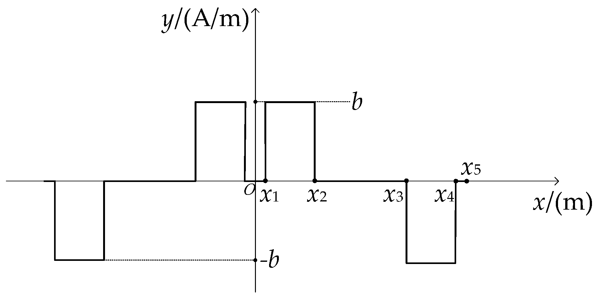
The distribution curve of linear current density at the interface of region I and region II is shown in Figure 2, and the abscissa expressions of the curves are shown in Table 1.
Fourier decomposition of the curve in Figure 2 shows that there are only odd components in the Fourier expression, which is shown below.
K ( I ) ( II ) z = n = 1 a n cos ( n π τ x ) n = 1 , 3 , 5
The expression of an is shown below.
a n = 2 b k π
The relationship between the linear current density constant b and the electric density J, the cross-sectional area S, the width bc of the exciting coil, and the full factor kf of the coil slot is given by the equation below.
b = J S k f b c
k is the linear current density distribution coefficient, which is given by the formula below.
k = π τ [ c 2 c 2 + b c cos ( n π τ x ) d x τ ( c 2 + b c ) τ c 2 cos ( n π τ x ) d x ]
According to Equation (12), and for convenience of calculation, the nth harmonic expression of linear density at the interface of region I and region II is given by the formula below.
K ( I ) ( II ) z n = a n e j n π τ x n = 1 , 3 , 5

2.4. Eddy Current Braking Force

In order to calculate the expression of braking force, the expressions of eddy current density and flux density in region III need to be calculated.
The nth harmonic expression of eddy current density Jwn in the induction plate can be obtained by combining Equation (7) along with Equations (9)–(16).
J w n = 2 j n π τ μ 0 σ v a n [ e ( n π τ α ) δ e α y + e ( n π τ + α ) δ + 2 α b g e α y ] ( n π τ + α ) [ 1 e 2 ( n π τ δ + α b g ) ] + ( n π τ α ) ( e 2 α b g e 2 n π τ δ ) e j n π τ x
where δ′ is the modified air gap length and bg is the induction plate thickness.
The magnetic density in region III is the sum of the magnetic density produced by exciting current and eddy current. Because the magnetic field generated by the eddy current in the induction plate does not work on the induction plate itself, there is only the magnetic field generated by the exciting current working on the induction plate in region III when calculating the braking force. The magnetic density in region III can be simplified to that in the static case (v = 0). Combined with Equations (9)–(16), in region III, the nth harmonic expression of magnetic density in the y direction is given by the equation below.
B ( III ) y n = A ( III ) z n x | v = 0 = j μ 0 a n e n π τ y + e 2 n π τ d e n π τ y 1 e 2 n π τ d e j n π τ x
where d = δ + bg.
Then, according to the ampere force formula [20], the nth harmonic calculation formula of braking force in the induction plate is given by the equation below.
F W n = l p w Re ( δ d J w ( B ( III ) y n ) * d y )
where lp = 2, which is the total length of eddy current braking device, p is the number of pole-pairs, w is the vertical paper depth of the device, and * represents the complex conjugate of a variable.
The nth harmonic expression of braking force is calculated using the equation below.
F W n = n π τ l p w μ 0 a n 2 [ M sin ( 2 N b g ) + N sin h ( 2 M b g ) ] 2 [ ( M Y 1 N Y 2 + n π τ Y 3 ) 2 + ( M Y 2 + N Y 1 + n π τ Y 4 ) 2 ]
{ M = ( n π τ ) 2 + n π τ [ ( n π τ ) 2 + μ 0 2 σ 2 v 2 ] 1 2 2 N = ( n π τ ) 2 + n π τ [ ( n π τ ) 2 + μ 0 2 σ 2 v 2 ] 1 2 2 Y 1 = cos h ( n π τ δ ) sin h ( M b g ) cos ( N b g ) Y 2 = cos h ( n π τ δ ) cos h ( M b g ) sin ( N b g ) Y 3 = sin h ( n π τ δ ) cos h ( M b g ) cos ( N b g ) Y 4 = sin h ( n π τ δ ) sin h ( M b g ) sin ( N b g )
Therefore, the expression of total braking force is given by the equation below.
F W = n = 1 F W n n = 1 , 3 , 5
In this paper, the expression of eddy current braking force (22) has been deduced, which is the key to analyze the peak braking force and the critical speed.

3. Finite Element Verification

According to the design requirement of a maglev project, a set of rated parameters is selected to design an FEA model of eddy current braking to verify the accuracy of the analytical formula of the braking force. The design parameters of the analytical and FEA model are shown in Table 2.
Since the linear brake is analyzed in this paper, there will be entry and exit effects when the brake moves. However, in Reference [6], it is mentioned that, if the brake exceeds four or more poles, the effects are insignificant. In this paper, the brake has 12 poles, so the entry and exit effects of the device are neglected in the analytical calculation.
According to the model parameters given in Table 2, the FEA simulation model of eddy current braking is set up in Ansoft Maxwell, as shown in Figure 3.
In Figure 3, the upper part is the eddy current braking device, which is composed of a yoke, poles, and exciting coils. The lower part is the rail, which is composed of an induction plate and a back iron.
And it is assumed that:
(1)
The magnetic field is simulated in 2D, and the Cartesian coordinate system and the International Unit System are used;
(2)
The lateral end effect has been neglected. The magnetic field distributes uniformly along the z-axis. The current density vector J and the magnetic potential vector A have only z-axis components.
In the FEA software, the eddy current braking model is simulated by the transient solver to verify the accuracy of the braking force analytical formula given in Equations (20), (21), and (22). Furthermore, Figure 4 and Figure 5 are the static magnetic line distribution and the static magnetic density distribution of the FEA simulation, respectively.
Figure 4 and Figure 5 can verify the accuracy of the model and its simulation. Additionally, it can also be seen from Figure 5 that the air gap magnetic density of the model is slightly less than 1.5 T, which is due to the saturation of magnetic circuit in the core that cannot be neglected in the FEA simulation.
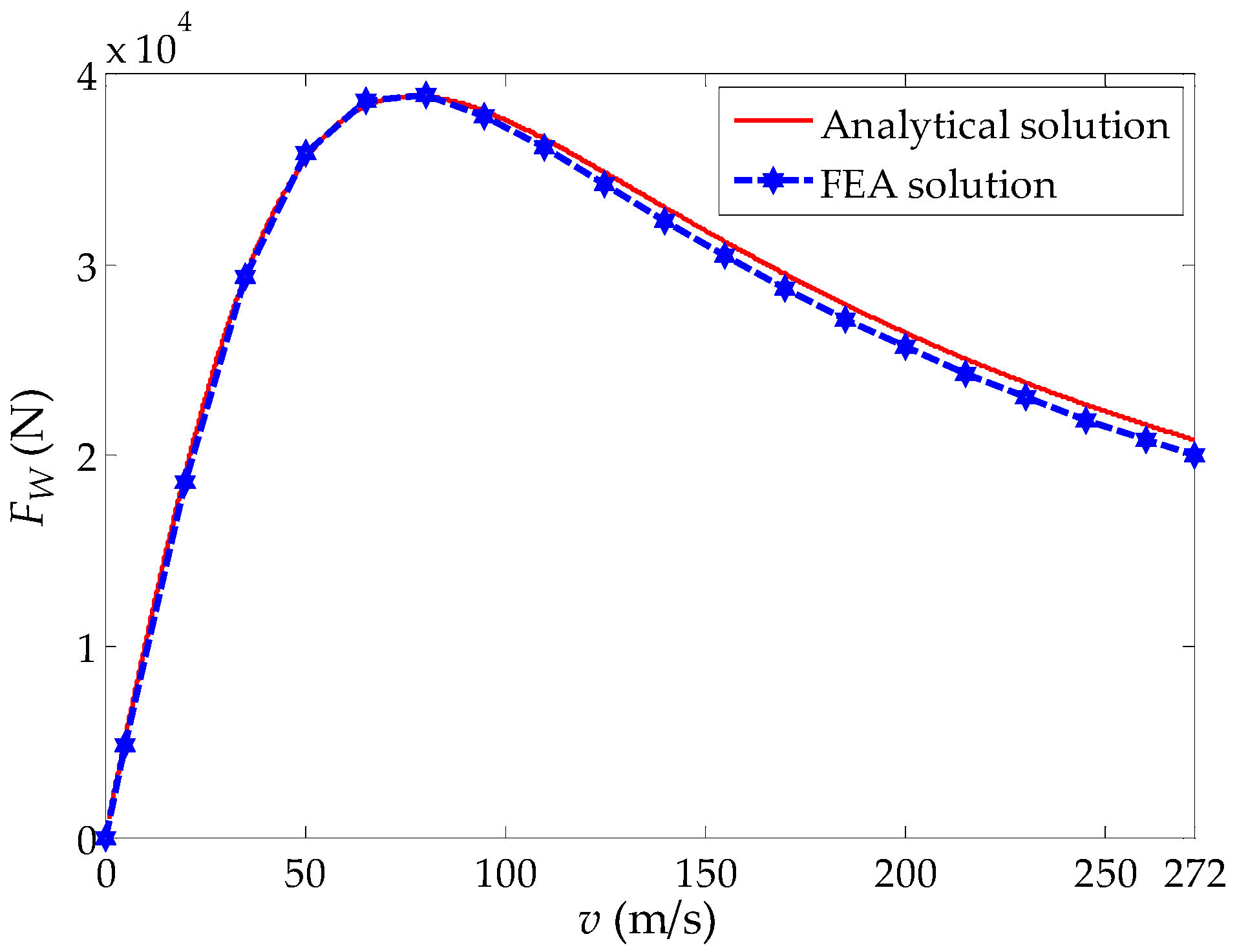
Figure 6 shows the analytical and simulation curves of the variation of eddy current braking force with speed.
It can be seen from Figure 6 that the analytical solution is in good agreement with the FEA solution, but the analytical result is slightly higher than the FEA solution at high speeds. This is due to the assumption that the relative permeability of the ferromagnetic region is infinite in the analytical calculation, while the loss of the ferromagnetic region increases at high speed in the FEA. Then, the braking force decreases in the FEA at high speed. From Figure 6, the correctness of the braking force analytical formula is verified by this simulation.
Additionally, it takes about 3 h to run one working point (corresponding to one simulation point in Figure 6, and there are 20 FEA simulation points in Figure 6) whose setting simulation time is 6 ms by FEA. In contrast, the result of one working point can be obtained immediately by the subdomain method calculation. In addition, the running time of simulation is also related to the accuracy of the model partition. The finer the partition, the longer the running time of simulation will be.

4. Parameter Analysis

Equation (22) can be regarded as a function FW(v) of eddy current braking force and speed. Since the skin effect of the induction plate is considered in this paper, the analytical formula of braking force becomes very complicated, which makes it difficult to obtain the expressions of the peak braking force and critical speed point by differentiating the function FW(v) with respect to v. Therefore, the dichotomy method is used to calculate the root derivative of function FW(v), which is the critical speed vm. Then the peak braking force FWm can be obtained.
Let the first derivative of function FW(v) be F′W(v). The root of F′W(v) is vm, which is the critical speed and is also the stationary point of FW(v). We take the velocity interval as [v1, v2] in the velocity range from 0 m/s to 272 m/s to make the following formula.
F W ( v 1 ) F W ( v 2 ) < 0
If
{ v c = v 1 + v 2 2 F W ( v c ) = 0
then vm = vc, otherwise
{ F W ( v 1 ) F W ( v c ) < 0 F W ( v 2 ) F W ( v c ) < 0
Judging which inequality in Equation (25) is correct, then the new velocity interval [v1, vc] or [vc, v2] is redefined to calculate by dichotomy until it reaches the condition of Equation (26).
| v a v b | < ζ
where va and vb are the endpoints of the velocity interval calculated by multiple dichotomies, and ζ is the given accuracy.
Then va or vb is the stationary point vm of FW(v) and the peak braking force FWm can be obtained by substituting vm into Equation (22).
Using the calculated value of critical speed and the peak braking force, the characteristics of the peak braking force and the critical speed of different working conditions are analyzed.

4.1. Effect of the Air Gap Length on the Peak Braking Force and the Critical Speed

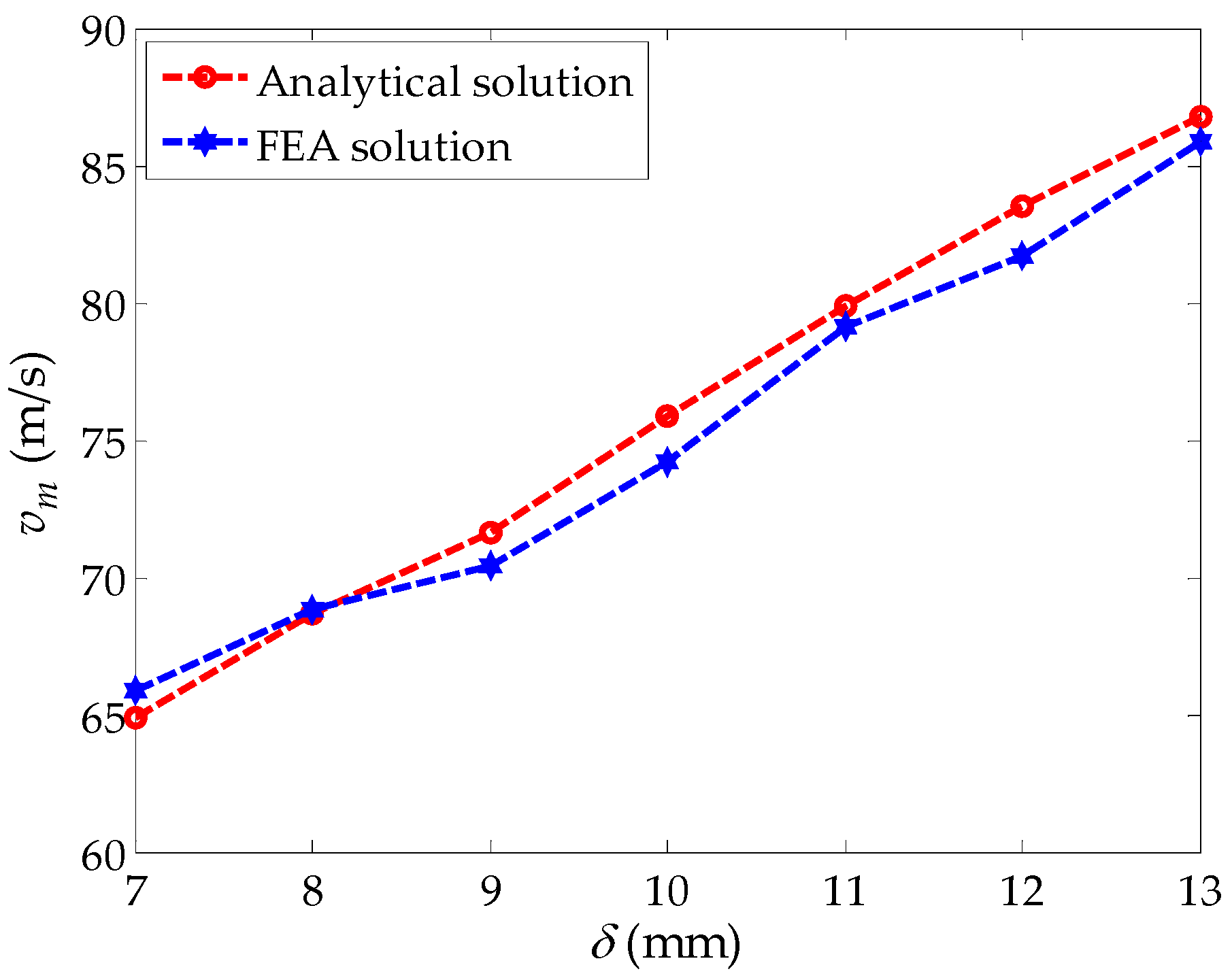
The air gap length is varied to study its impact on the peak braking force and critical speed while keeping other rated parameters unchanged. Figure 7 and Figure 8 show the analytical and simulation curves of peak braking force FW and critical speed vm varying with the air gap length δ, respectively.
As can be seen from Figure 7 and Figure 8, a shorter air gap length is preferred since it leads to higher peak braking force values, while the critical speed represents the opposite. Therefore, the relationship between peak braking force and critical speed is mutually restricted by the change of the air gap length. When the air gap changes, one of the factors increases and the other decreases. Therefore, the appropriate air gap length should be selected according to the demand of actual working conditions to satisfy the value of the peak braking force and the critical speed.

4.2. Effect of the Pole Pitch on the Peak Braking Force and the Critical Speed

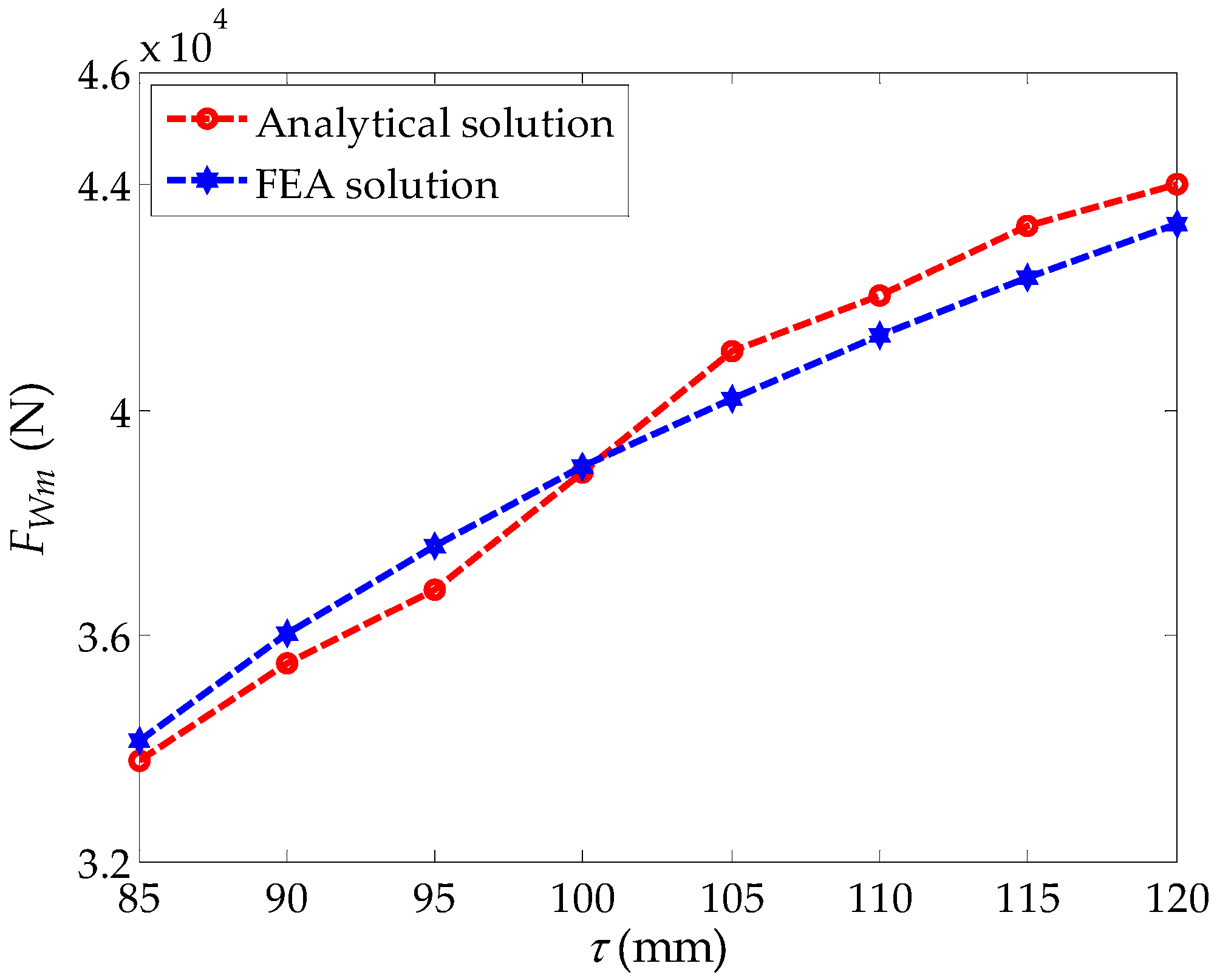
The influence of the pole pitch on peak braking force and critical speed is studied. The analytical and simulation curves of peak braking force and critical speed varying with the pole pitch are given in Figure 9 and Figure 10, respectively.
From Figure 9 and Figure 10, it can be seen that the variation tendency of the analytical solution is basically consistent with that of the FEA solution. Similar to the effect of air gap length on peak braking force and critical speed, the relationship between peak braking force and critical speed is also mutually restricted by the change of the pole pitch. The peak braking force increases with the increase of the pole pitch, but the critical speed decreases. The influence of the pole pitch on peak braking force and critical speed can guide the selection of the pole pitch.

4.3. Effect of the Thickness of the Induction Plate on Peak Braking Force and Critical Speed

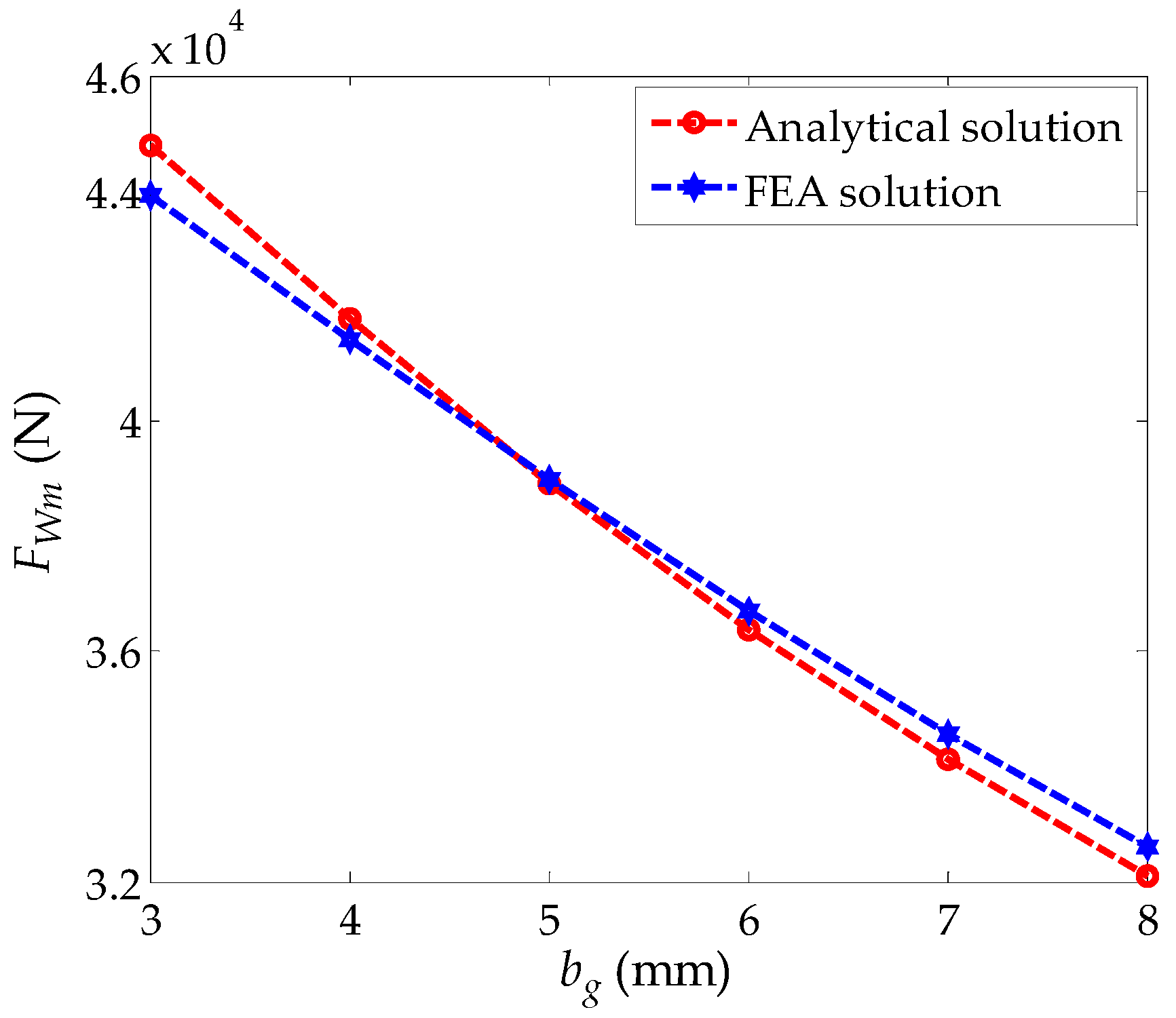
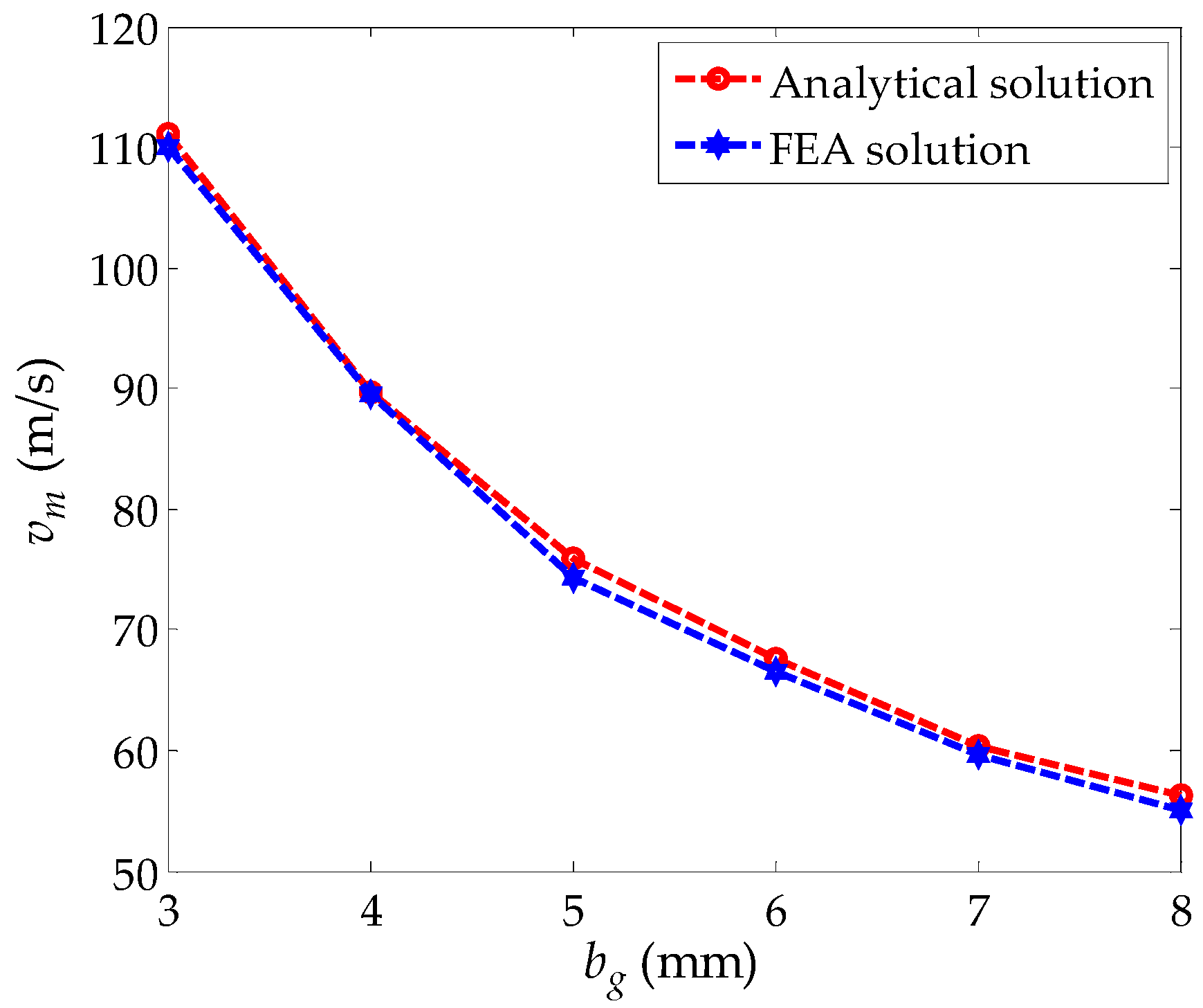
The influence of the thickness of the induction plate on peak braking force and critical speed is studied. The analytical and simulation curves of peak braking force and critical speed varying with the thickness of the induction plate are given in Figure 11 and Figure 12, respectively.
From Figure 11 and Figure 12, it can be seen that the peak braking force and critical speed increase with the decrease of induction plate thickness. In addition, the critical speed increases in a trend of quadratic function. This is because the eddy current in the induction plate decreases and the eddy current magnetic field decreases as the thickness of the induction plate decreases. Therefore, if the eddy current magnetic field is to reach its original strength, it needs to increase the speed. Therefore, the critical speed increases with the thickness of the induction plate decreases. At the same time, the effective air gap length d decreases and the air gap magnetic field increases with the decrease of the thickness of the induction plate. Therefore, the peak braking force increases accordingly. In order to improve the performance of eddy current braking force at high speeds, the selection of a thinner induction plate can increase the peak braking force and the critical speed simultaneously.

4.4. Effect of Induction Plate Conductivity on Peak Braking Force and Critical Speed

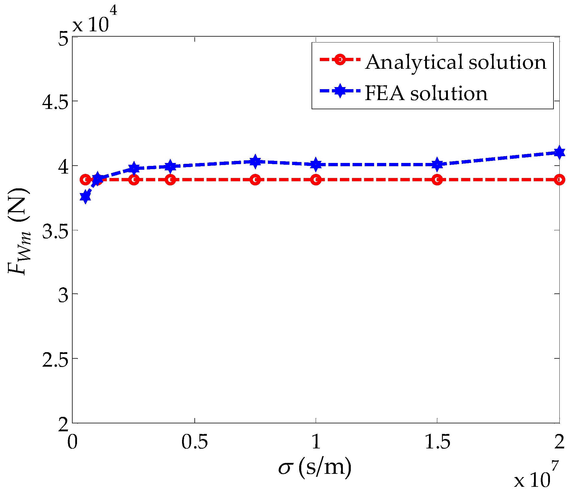
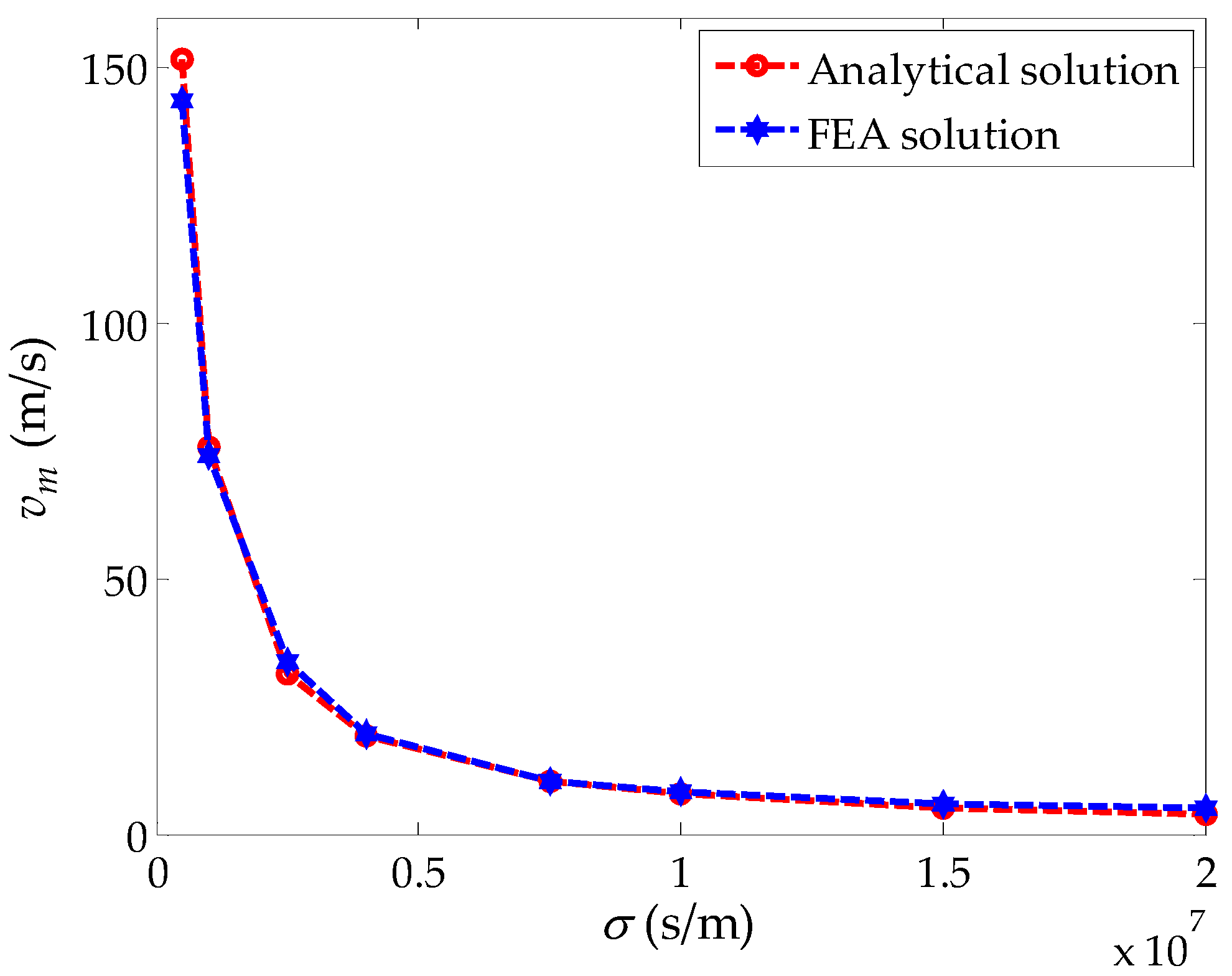
The analytical and simulation curves of peak braking force and critical speed varying with the induction plate conductivity are given in Figure 13 and Figure 14, respectively.
As can be seen from Figure 13, the induction plate conductivity has no influence on the peak braking force. Furthermore, as can be seen from Figure 14, the critical speed is strictly an inverse function of the conductivity. Similar to the effect of induction plate thickness, the decrease of the conductivity of the induction plate also weakens the eddy current magnetic field. If the eddy current magnetic field is to reach its original strength, it needs to increase the speed. Therefore, the critical speed increases when the conductivity of the induction plate decreases. In this paper, the range of the induction plate conductivity is 5 × 10⁵ s/m to 2 × 10⁷ s/m in the simulation. In this range, choosing the induction plate material with lower conductivity can improve the value of critical speed, and then can improve the performance of braking force at high speed.

5. Error Analysis

Here is the error analysis of the analytical solution and the FEA solution. Table 3 shows the maximum error of the analytical solution and the FEA solution corresponding to the peak braking force and the critical speed with different variables.
Among the three parameters of the air gap length, the pole distance, and the thickness of induction plate, the maximum error between the analytical solution and the FEA solution is less than 3%. Regarding induction plate conductivity, the maximum error between the analytical solution and the FEA solution of peak braking force is 5.09%, but the maximum error for the critical speed is 21.4%, which is relatively large. This is because, with the increase of conductivity, the value of the critical speed becomes very small. A small error between the analytical solution and the FEA solution can also cause a large value in percentage. The average error for the critical speed is 7.36% regarding plate conductivity, which is less than 10%. In conclusion, the errors between analytical solution and the FEA solution are within a reasonable range. The main reasons for these errors are that the saturation of the ferromagnetic region is not taken into account and the lateral end effect of the model is neglected in the analytical calculation.

6. Conclusions

This paper focuses on these two characteristics of eddy current braking force and has revealed how various design parameters can influence them. The analytical formula of eddy current braking force in the high-speed maglev exciting eddy current braking system is obtained by the subdomain method, and the accuracy of this formula is verified by FEA. To increase the braking force at high speeds, the appropriate air gap and pole pitch should be selected according to the demand in actual working conditions. The plate thickness should be as thin as possible and the conductivity should be as small as possible in the range of the induction plate conductivity selected in this paper while meeting other engineering requirements. The results provided in this paper can provide theoretical guidance for the preliminary design and optimization of the eddy current braking system in the high-speed maglev test line.

Author Contributions

C.C. conceived and designed the study. He was also responsible for the theoretical calculations and simulations. This work was performed under the advisement and regular feedback from X.W., J.X. and X.Y.

Funding

This research was funded by National Natural Science Foundation of China grant number: 51677092. And The APC was funded by National Natural Science Foundation of China.

Conflicts of Interest

The authors declare no conflict of interest.

References

  1. Thompson, M.T. Practical issues in the use of NdFeB permanent magnets in maglev, motors, bearings and eddy current brakes. Proc. IEEE 2009, 97, 1758–1767. [Google Scholar] [CrossRef]
  2. Wang, P.J.; Chiueh, S.J. Analysis of eddy-current brakes for high speed railway. IEEE Trans. Magn. 1998, 34, 1237–1239. [Google Scholar] [CrossRef]
  3. Kou, B.; Jin, Y.; Lu, Z.; He, Z. Characteristic analysis and control of a hybrid excitation linear eddy current brake. Energies 2015, 8, 7441–7464. [Google Scholar] [CrossRef]
  4. Srivastava, R.K.; Kumar, S. An alternative approach for calculation of braking force of an eddy-current brake. IEEE Trans. Magn. 2009, 45, 150–154. [Google Scholar] [CrossRef]
  5. Cho, S.; Liu, H.; Han, W.A.; Ju, L.; Lee, H.W. Eddy current brake with a two-layer structure: Calculation and characterization of braking performance. IEEE Trans. Magn. 2017, 53, 8110205. [Google Scholar] [CrossRef]
  6. Edwards, J.D.; Jayawant, B.V.; Dawson, W.R.C.; Wright, D.T. Permanent-magnet linear eddy-current brake with a nonmagnetic reaction plate. IEE Proc. Electr. Power Appl. 1999, 146, 627–631. [Google Scholar] [CrossRef]
  7. Yazdanpanah, R.; Mirsalim, M. Axial-flux wound-excitation eddy-current brakes: Analytical study and parametric modeling. IEEE Trans. Magn. 2014, 50, 1–10. [Google Scholar]
  8. Xue, Z.; Li, H.; Zhou, Y.; Ren, N.; Wen, W. Analytical prediction and optimization of cogging torque in surface-mounted permanent magnet machines with modified particle swarm optimization. IEEE Trans. Ind. Electron. 2017, 64, 9795–9805. [Google Scholar] [CrossRef]
  9. Zhou, Y.; Li, H.; Meng, G.; Zhou, S.; Cao, Q. Analytical calculation of magnetic field and cogging torque in surface-mounted permanent-magnet machines accounting for any eccentric rotor shape. IEEE Trans. Ind. Electron. 2015, 62, 3438–3447. [Google Scholar] [CrossRef]
  10. Shin, H.J.; Choi, J.Y.; Cho, H.W.; Jang, S.M. Analytical torque calculations and experimental testing of permanent magnet axial eddy current brake. IEEE Trans. Magn. 2013, 49, 4152–4155. [Google Scholar] [CrossRef]
  11. Yazdanpanah, R.; Mirsalim, M. Analytical study of axial-flux hybrid excitation eddy current brakes. Int. J. Appl. Electromagn. Mech. 2015, 47, 885–896. [Google Scholar] [CrossRef]
  12. Canova, A.; Vusini, B. Design of axial eddy-current couplers. IEEE Trans. Ind. Appl. 2003, 39, 725–733. [Google Scholar] [CrossRef]
  13. Paudel, N.; Bird, J.Z. General 2-D steady-state force and power equations for a traveling time-varying magnetic source above a conductive plate. IEEE Trans. Magn. 2012, 48, 95–100. [Google Scholar] [CrossRef]
  14. Jin, Y.; Kou, B.; Li, L.; Pan, D. Thermal analysis of a hybrid excitation linear eddy current brake. IEEE Trans. Ind. Electron. 2019, 66, 2987–2997. [Google Scholar] [CrossRef]
  15. Jiao, Z.; Wang, T.; Liang, Y. Design of a tubular linear oscillating motor with novel compound halbach magnet array. IEEE/ASME Trans. Mechatron. 2017, 22, 498–508. [Google Scholar] [CrossRef]
  16. Gysen, B.L.J.; Meessen, K.J.; Paulides, J.J.H.; Lomonova, E.A. General formulation of the electromagnetic field distribution in machines and devices using fourier analysis. IEEE Trans. Magn. 2010, 46, 39–52. [Google Scholar] [CrossRef]
  17. Liu, Z.J.; Vourdas, A.; Binns, K.J. Magnetic field and eddy current losses in linear and rotating permanent magnet machines with a large number of poles. Sci. Meas. Technol. IEE Proc. A 1991, 138, 289–294. [Google Scholar] [CrossRef]
  18. Kou, B.; Jin, Y.; Zhang, H.; Lu, Z. Analysis and design of hybrid excitation linear eddy current brake. IEEE Trans. Energy Convers. 2014, 29, 496–506. [Google Scholar]
  19. Kou, B.; Jin, Y.; Zhang, H.; Zhang, L. Nonlinear analytical modeling of hybrid-excitation double-sided linear eddy-current brake. IEEE Trans. Magn. 2015, 51, 8003404. [Google Scholar] [CrossRef]
  20. Kawai, T.; Inamori, T.; Hori, K. Analytical lorentz force model between 1-D linear currents in arbitrary relative positions and directions. IEEE Trans. Magn. 2018, 54, 1–16. [Google Scholar] [CrossRef]
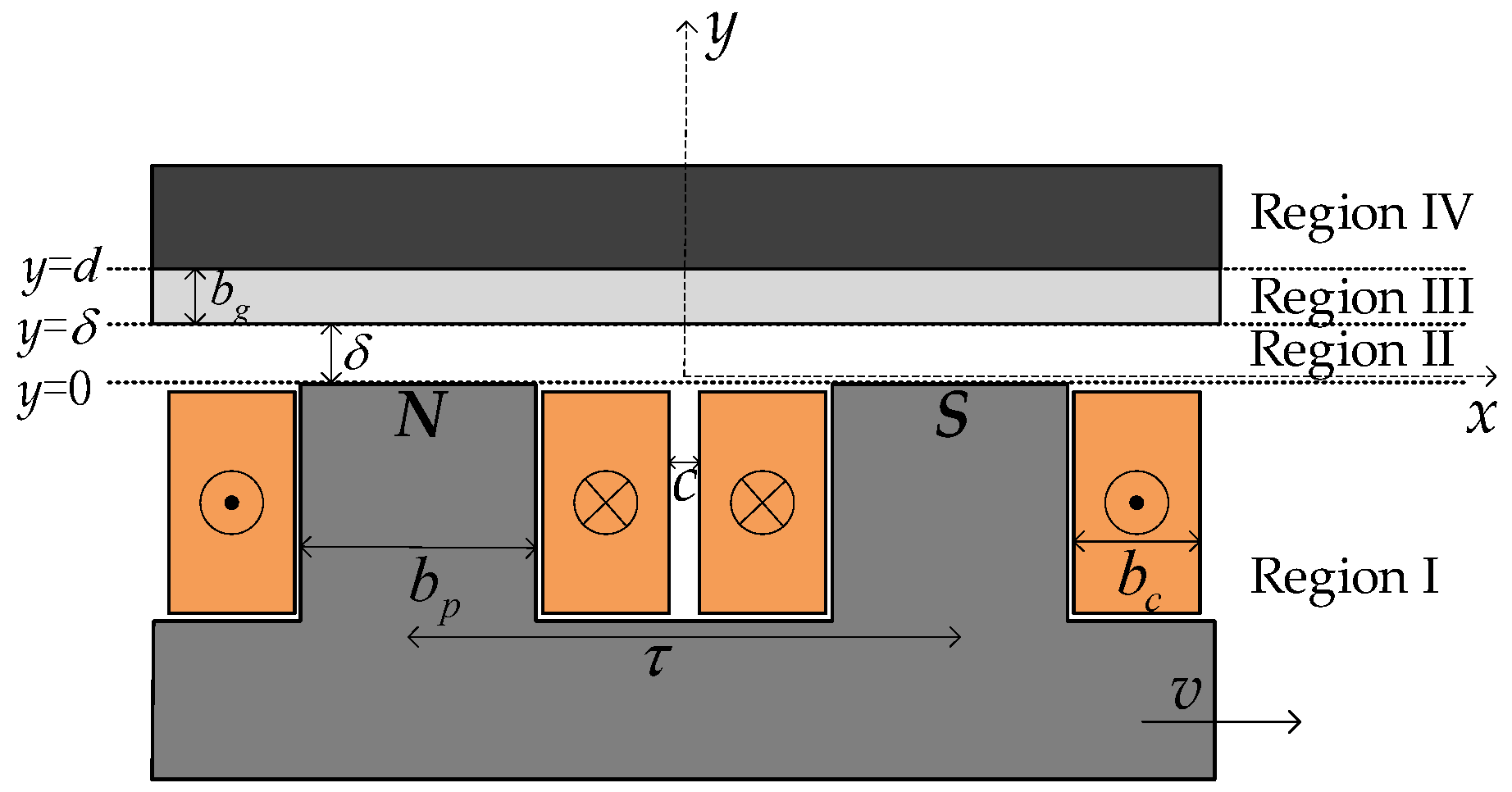
Figure 1. 2D simplified eddy current braking model.
Energies 12 02622 g001
Figure 2. Distribution of equivalent linear current density at the interface of region I and region II.
Energies 12 02622 g002
Figure 3. FEA model of eddy current braking.
Energies 12 02622 g003
Figure 4. Distribution field diagram of the static magnetic line.
Energies 12 02622 g004
Figure 5. Distribution field diagram of static magnetic density.
Energies 12 02622 g005
Figure 6. Eddy current braking force varying with speed.
Energies 12 02622 g006
Figure 7. The peak braking force varying with the air gap length.
Energies 12 02622 g007
Figure 8. The critical speed varying with the air gap length.
Energies 12 02622 g008
Figure 9. The peak braking force varying with the pole pitch.
Energies 12 02622 g009
Figure 10. The critical speed varying with the pole pitch.
Energies 12 02622 g010
Figure 11. The peak braking force varying with the induction plate thickness.
Energies 12 02622 g011
Figure 12. The critical speed varying with the induction plate thickness.
Energies 12 02622 g012
Figure 13. The peak braking force varying with the induction plate conductivity.
Energies 12 02622 g013
Figure 14. The critical speed varying with the induction plate conductivity.
Energies 12 02622 g014
Table 1. Abscissa expression in Figure 2.
ParameterValue
x1c/2
x2c/2 + bc
x3τ − (c/2 + bc)
x4τc/2
x5τ
Table 2. Basic parameters of the eddy current braking model.
ParameterValue
number of pole pairs p6
maximum operating speed vmax272 m/s
exciting current density J12 A/mm2
static air gap magnetic density B01.5 T
the fill factor kf0.687
height of exciting coil hc115 mm
width of exciting coil bc15.3 mm
pole pitch τ100 mm
air gap length δ10 mm
height of yoke hs120 mm
height of pole hp120 mm
width pole bp69.2 mm
thickness of induction plate bg5 mm
thickness of back iron bs30 mm
model depth w200 mm
induction plate conductivity σ106 S·m−1
setting simulation time6 ms
Note: The model is simulated 160 times in the setting simulation time of 6 ms, which means the model is simulated every 0.0375 ms.
Table 3. Maximum error of the analytical solution and FEA solution.
VariablePeak Braking ForceCritical Speed
air gap length1.89%2.25%
pole pitch2.17%2.25%
induction plate thickness2.01%2.16%
induction plate conductivity5.09%21.4%