1. Introduction
Photovoltaic energy conversion has already become one of the most reliable energy resources. Further reduction of the system costs is a must in order to fulfill the increasing demand for energy all over the world. In order to achieve such a cost reduction, the solar cell output power could be increased by the use of either stationary or tracking solar concentrator subsystems [
1]. One disadvantage of concentrator photovoltaic systems (CPV) is that they require direct sunlight as they cannot operate effectively with diffuse radiation, meaning some sort of sun-tracking system is required, which adds to the system complexity and total cost of the operation. The operating temperature of PV cells plays an important role in determining their electrical output because part of the incident solar energy is converted into electricity while the remaining part is converted into heat [
2,
3,
4,
5]. This adds another disadvantage to using such concentrating systems because of the elevated PV cell’s temperature. While the generated current of the PV cells increases slightly with temperature, the corresponding voltage decreases considerably with temperature elevation. This reduces the fill factor, output power, and electrical conversion efficiency accordingly.
In order to minimize the increase in cell temperature that would lead to such a reduction in the conversion efficiency, heat generated in the CPV cells should be removed by cooling subsystems attached to the back surface of the cell [
6,
7]. Many studies have been carried out to find efficient methods for passive and active cooling for CPV cells, and at the same time, harvesting additional power gain through the use of heat collected from such CPV cells.
On the other hand, a thermoelectric generator (TEG) is a simple and reliable electric device based on the Seebeck effect that converts thermal energy directly into electrical energy. The TEG module has many advantages beside being environmentally friendly such as having no moving parts and being quiet [
8]. The major disadvantage of the TEGs is their relatively low conversion efficiency.
An attempt to concentrate sunlight directly on a TEG module along with a numerical method for system performance evaluation has a predicted system efficiency of up to 14% [
9]. A 4.6% peak efficiency of a high thermal concentration solar flat-panel TEG system under a thermal concentration ratio of 299 kW/m
2 and global air mass of 1.5 has been reported by other work [
10]. Others [
11] have tested a solar parabolic dish concentrator along with a TEG system that was able to produce electric power up to 5.9 W under a temperature difference between the hot and cold sides of 35 °C with the hot-side temperature being at 68 °C. A three-dimensional finite-element model considering a solar thermoelectric device system has been carried out, and it suggested that total efficiency could reach 9.95% if the contact resistance and all heat losses are neglected [
12]. A model has been developed and simulated by others considering a thermoelectric cooling module attached to the back side of a PV cell, assuming that the required power to run such a module is provided by the PV cell itself. Results showed that using thermoelectric cooling modules can control the temperature of the PV cell by using a reasonable amount of electricity [
13].
In this work, a system comprised of a TEG module, a CPV cell, and a heat sink is proposed. The cold side of the TEG was proposed to be thermally attached to a heat sink, while its hot side was proposed to be in thermal contact with the back surface of the CPV cells. This will have two-fold benefits; first, it will cool down the PV cell, resulting in increasing its output power. Second, there will be a temperature difference between the TEG hot surface (where the PV cell is proposed to be lying on top) and the TEG cold surface (where the heat sink is attached), resulting in the generation of electrical power due to the Seebeck effect.
2. Photovoltaic/Thermal (PV/T) Hybrid System
The PV current–volt relation is given by the following well known one diode model [
14]:
where
is the photo-generated current;
is the dark current,
is the electron charge;
and
are series and shunt resistances, respectively;
is Boltzmann’s constant;
is the PV cell temperature; and
is the ideality factor. Increasing the solar irradiance incident on the PV surface (using solar concentrators) will increase the output current, but will elevate its temperature as well, resulting in reducing the output voltage accordingly, resulting in a reduction of the PV cell’s efficiency
. Several models relating
of the PV cell with its temperature
have been proposed. A simple model used in this work is expressed as [
15]:
where
is the PV cell efficiency at the operating temperature
, and
is the reference efficiency measured at the reference temperature
.
is the temperature coefficient of efficiency, which is the fractional reduction of the PV cell efficiency per unit temperature increase (%/°C).
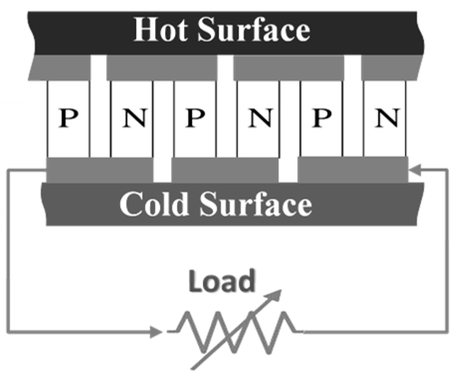
Typically, in a commercial TEG module (shown schematically in
Figure 1), ceramic substrates are on either external side of the module, and
N-type/
P-type semiconductors are placed parallel to each other and connected in series between these ceramic plates. Applying a temperature difference between the TEG sides will generate electrical power in accordance with the Seebeck effect [
16].
It is found that the generated potential difference
V across a junction of two different materials is represented by [
17]:
where
is the Seebeck coefficient and
is the temperature difference between the two TEG sides. The performance of TEG module is evaluated in terms of the figure of merit
, a dimensionless parameter defined as [
17]:
where
and
are the electrical resistivity and thermal conductivity, respectively, and
is the average temperature of the TEG module. The TEG electrical efficiency is expressed as [
17]:
where
and
are the hot and cold side temperatures, respectively.
In order to achieve the maximum power of the TEG, the value of the load resistance has to be optimized. It has been found that the load resistance should be equal to the TEG internal resistance [
18] for attaining maximum power.
3. Experimental Setup and Measurements
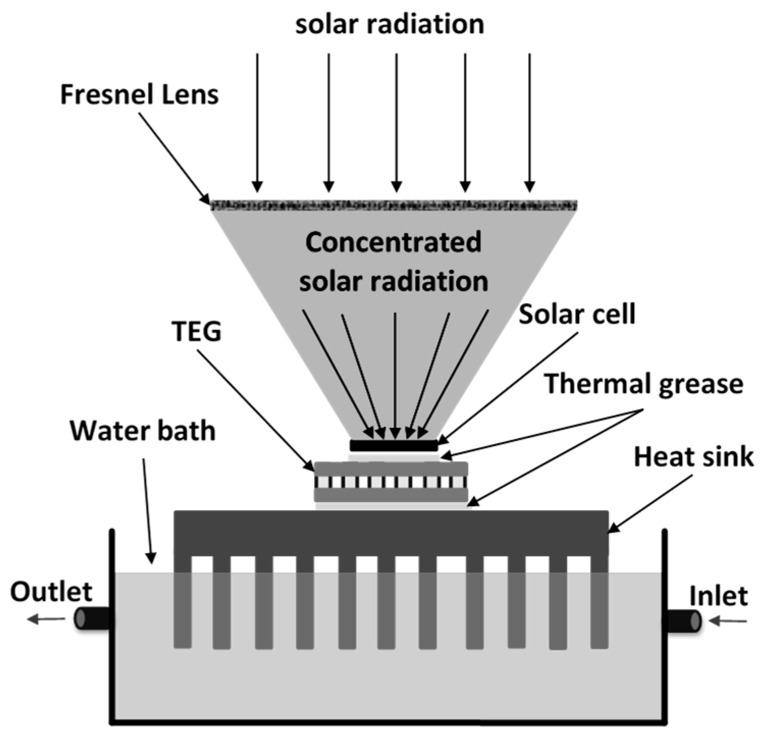
Figure 2 shows an ideal system that proposes a TEG module whose cold side is in thermal contact with a heat sink while concentrator PV cells are placed on top of its hot side. In seeking consistent indoor experiment repetition, concentrated PV cells, as well as the concentrated light, were replaced by electrical resistance heaters, as will be discussed in detail later on in this section.
Solar radiation of intensity was assumed to be incident on a Fresnel lens with surface area , and the concentrated solar radiation was incident on the PV that had an electrical conversion efficiency and surface area Asc.
The concentrated solar radiation of power
received by such a PV cell is expressed by:
where
is the optical efficiency of the Fresnel lens and is assumed to be 85% [
19,
20]. This received solar radiation power is partially converted into electricity
, while the remaining part is dissipated as heat
generated inside the PV cell, and is transferred to the top side of TEG.
The heat transferred from the PV cell is determined using the following equation [
20]:
To perform consistent indoors experimental tests repeatedly, as mentioned above, the proposed PV cells exposed to concentrated solar radiation were replaced by electrical resistance heaters, and are labelled as “1R”, “2R”, etc., which represent one PV cell, two PV cells, etc. Those electrical heaters were used to simulate the same amount of heat generated in the PV cells when exposed to concentrated solar radiation according to Equation (7). Five 60-watt, high power electrical resistors having dimensions of 12 mm × 8.5 mm × 3.1 mm were used to generate the desired amount of heat that is absorbed by the top surface of the TEG. Each heat element was connected to a power supply to control the electrical power feeding each element. The TEG top surface was assumed to be partially exposed to thermal energy. The active area of the TEG’s top surface absorbing thermal energy was simply the number of electrical heating elements attached to its surface multiplied by the effective area of each element.
Two different TEG modules of the same material and surface area were used to investigate the electrical performance of the proposed system. Properties of the used TEGs are listed in
Table 1.
The temperatures of both the top and bottom surfaces of the TEG were measured simultaneously using K-type thermocouples. The open circuit voltage and short circuit current of the TEG were recorded using digital multimeters in order to calculate the generated electrical power of the TEG without any load.
The generated thermal power in each heating element was controlled by adjusting the values of current and voltage supplied by the power supply that was connected to the heating element. This thermal power was then transferred to the TEG via a good thermal contact. Thus, the total thermal power transferred to the TEG was the summation of the electrical power consumed by all the heaters in contact with the upper surface of the TEG.
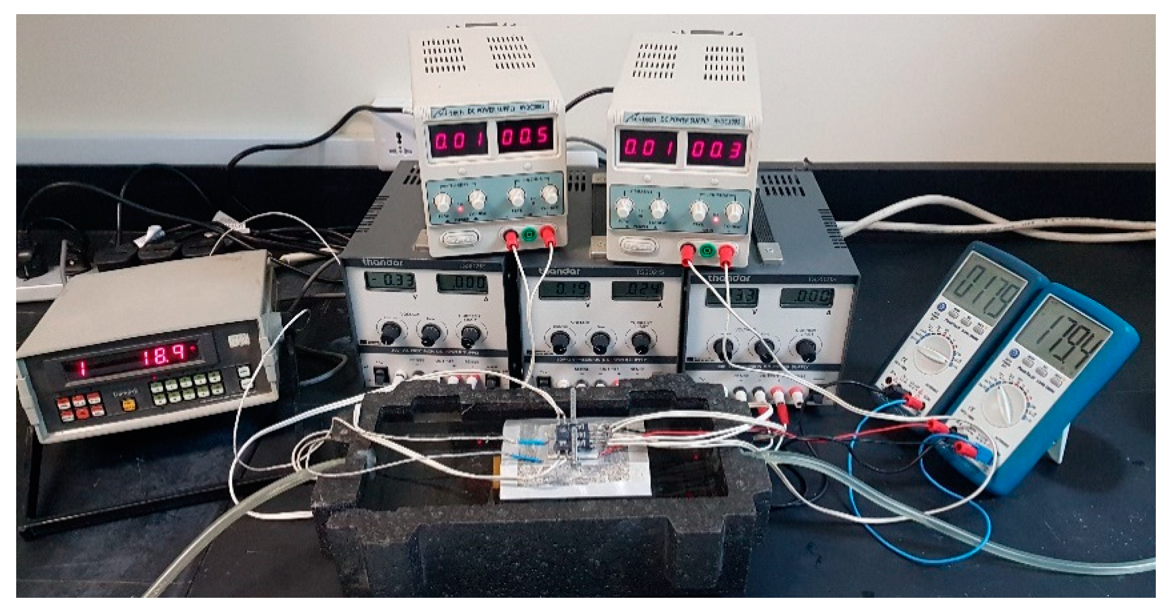
A thin layer of thermal grease was applied between the heating elements and the TEG module as well as between the TEG and the heat sink prior to applying a moderate mechanical pressure to ensure good thermal contact and maximum heat flow between the different parts of the system. Fins of the heat sink were immersed in a water tank with flowing water whose inlet temperature fixed at 20 °C. The whole experimental setup used in this study is shown in
Figure 3.
4. Results and Discussion
4.1. TEG Performance Under Concentrated Solar Radiation
In this section, the predicted output power of the TEG under partial covering of its hot surface with thermal energy is investigated without involving PV cells. The thermal input power to the TEG was calculated directly from the electrical power supplied to the heating elements. The electrical power supplied to each of the heating elements was assumed to be completely dissipated as heat transferred to the hot surface of the TEG module, calculated from Equation (8):
where
and
are the current and voltage applied to the heating elements from the supplying power source. Such heating elements were added one by one onto the TEG’s hot surface to gradually increase the percentage of its heated area. In each step, the total electrical power input to these heating elements was increased gradually, resulting in heating up the TEG upper surface. The measurements were taken at every increment of the inputted electrical power to the heating elements.
Figure 4 shows the temperature difference between the hot and cold surfaces of the TEG with increasing numbers of heating elements, from which the percentage area of the heated surface to the total TEG hot surface area was calculated. The radiation intensity could be expressed in terms of an emulated optical concentration ratio X, assuming that a radiation intensity incident on the surface of the Fresnel lens of 1000 W/m
2 is equivalent to 1X. The maximum percentage of the covered area was 32.5% of the total TEG hot surface area using five heating elements. Increasing the covered area beyond 32.5% of the total TEG upper surface resulted in temperature levels beyond the values recommended by the manufacturers of both TEGs.
Three emulated optical concentration ratios were selected: 70X, 100X, and 130X for both TEGs, and the heat sink fins were immersed in a bath having flowing water whose inlet temperature was 20 °C. TEG1 showed a higher temperature difference than that of TEG2, because of the higher number of junctions of the latter, and hence a better dissipation of thermal energy as well as higher electrical output, as will be shown later on.
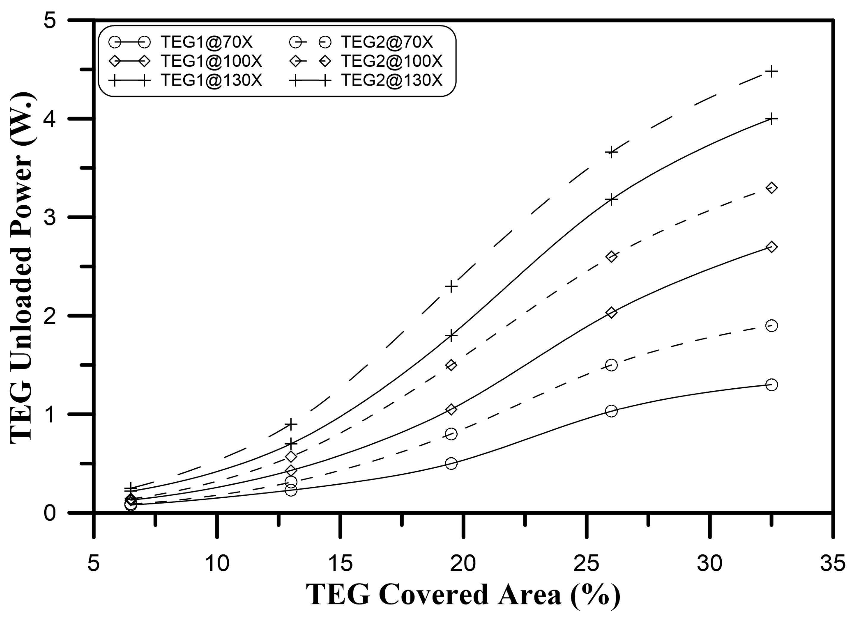
Unloaded power generated by the TEGs was increased as a result of increasing the heated area, as shown in
Figure 5. The figure shows the unloaded output power of the two TEG modules at three different emulated optical concentration ratios of 70X, 100X, and 130X. A nonlinear increase in the output power of both TEGs was measured with a smaller area covered, while an asymptotic increase of the TEG output power was predicted when the covering area was increased further.
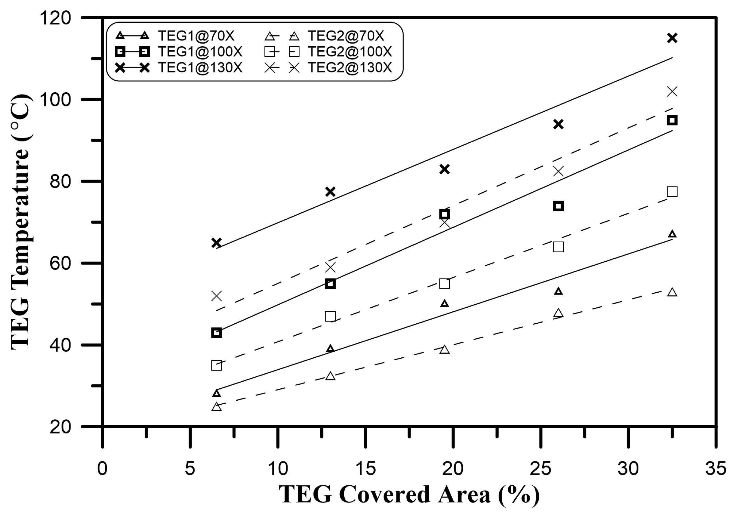
Increasing the area of the presumed PV cells on top of the TEGs (that were replaced by heating elements in this study) resulted in a greater increase in the overall system temperature compared to that of a system whose PV cells were in direct thermal contact with the heat sink only (without any intermediate TEG). This increase in temperature reduced the electrical output power of the PV cells. Such a reduction in the PV electrical output was subsidized by the electrical power generated by the TEG. The PV cells’ temperature (represented by the temperature of the heating elements) was measured at different emulated optical concentration ratios and plotted in
Figure 6. In this figure, 1R represents a CPV/TEG system with one PV cell (i.e., one heating element) attached on top of it, and 3R represents a CPV/TEG system with three PV cells attached, and so on. The number of heating elements placed on the TEG was then increased one by one, and the temperature of the hot surface representing the PV cells was measured at each step. Heating elements connected to the heat sink only (without TEGs) showed the lowest temperatures compared to those connected to either of the TEG modules. This was because there were no intermediate objects between the heating elements and the heat sink (except for a thin layer of thermal grease to increase thermal conductivity). Hence, such a configuration had better heat dissipation. Introducing TEG elements resulted in an expected rising system temperature (because of the TEG thermal resistances), hence reducing the electric output power of the proposed PV cells accordingly, as will be discussed later.
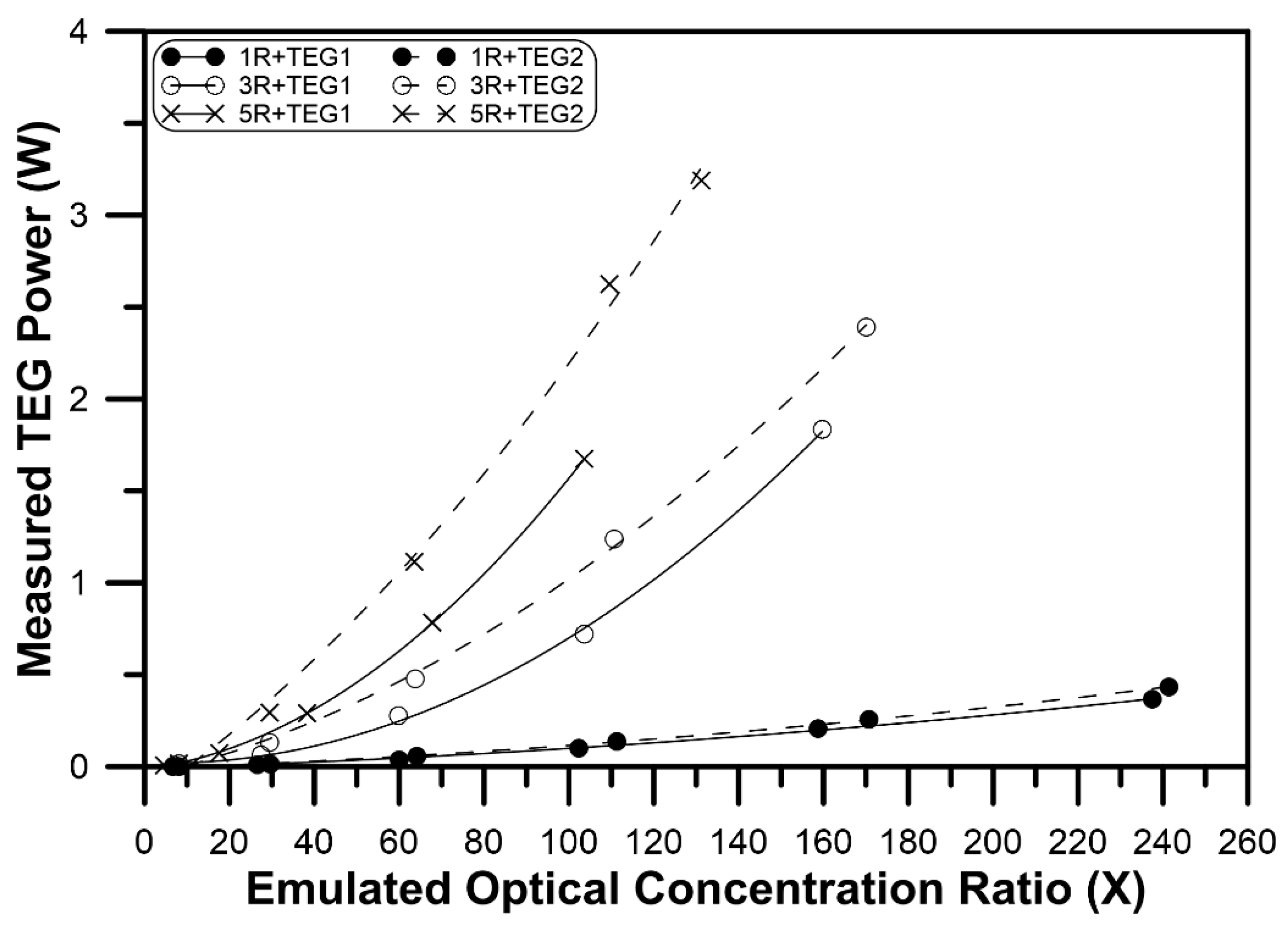
The electrical power generated in both TEG modules as a function of the emulated optical concentration ratio was measured with a load resistance equal to the internal resistance for each of the TEG modules that were tested (listed in
Table 1).
Figure 7 shows that the generated power reached about 2.4 W and 3.2 W at a 32.5% coverage area (i.e., using five heating elements) for TEG1 and TEG2, respectively, under a concentrated solar radiation of 130X.
4.2. Performance of the PV/T Coupled System
In this section, an investigation of a CPV/TEG coupled system is given involving PV cells, knowing their electrical parameters, and predicting the total system (PV as well as TEG) output power. Performance calculations of two different PV cells with different efficiencies and efficiency temperature coefficients coupled to the different TEGs were carried out. The chosen cells were a Ga
0.35In
0.65P/Ga
0.83In
0.17As dual-junction cell [
21], and a laser grooved buried contact (LGBC) cell optimized for linear concentration systems [
22]. The electrical parameters of these PV cells are listed in
Table 2, including PV efficiency (
η), efficiency temperature coefficient (
β), and the optical concentration ratio (X) under which these parameters have been reported.
It was assumed that such PV cells were thermally attached on top of the TEGs under investigation. The electrical output of the PV cells, as well as the total system electrical output, were predicted.
The PV output power was calculated for the Ga
0.35In
0.65P/Ga
0.83In
0.17As multijunction cell, as shown in
Figure 8, while that of the Silicon LGBC concentrator PV cell is shown in
Figure 9. Also, output powers were calculated in the case of an emulated PV/TEG system coupling the PV cells to TEG1 and TEG2 for multijunction and Si PVs, as shown in
Figure 10 and
Figure 11, respectively.
As expected, the electrical output was higher for both PV cells themselves in the case of direct attachment to the heat sink than in the case of coupling to the TEGs. This was due to the elevation of the PV cells’ temperatures, as discussed previously and shown in
Figure 6.
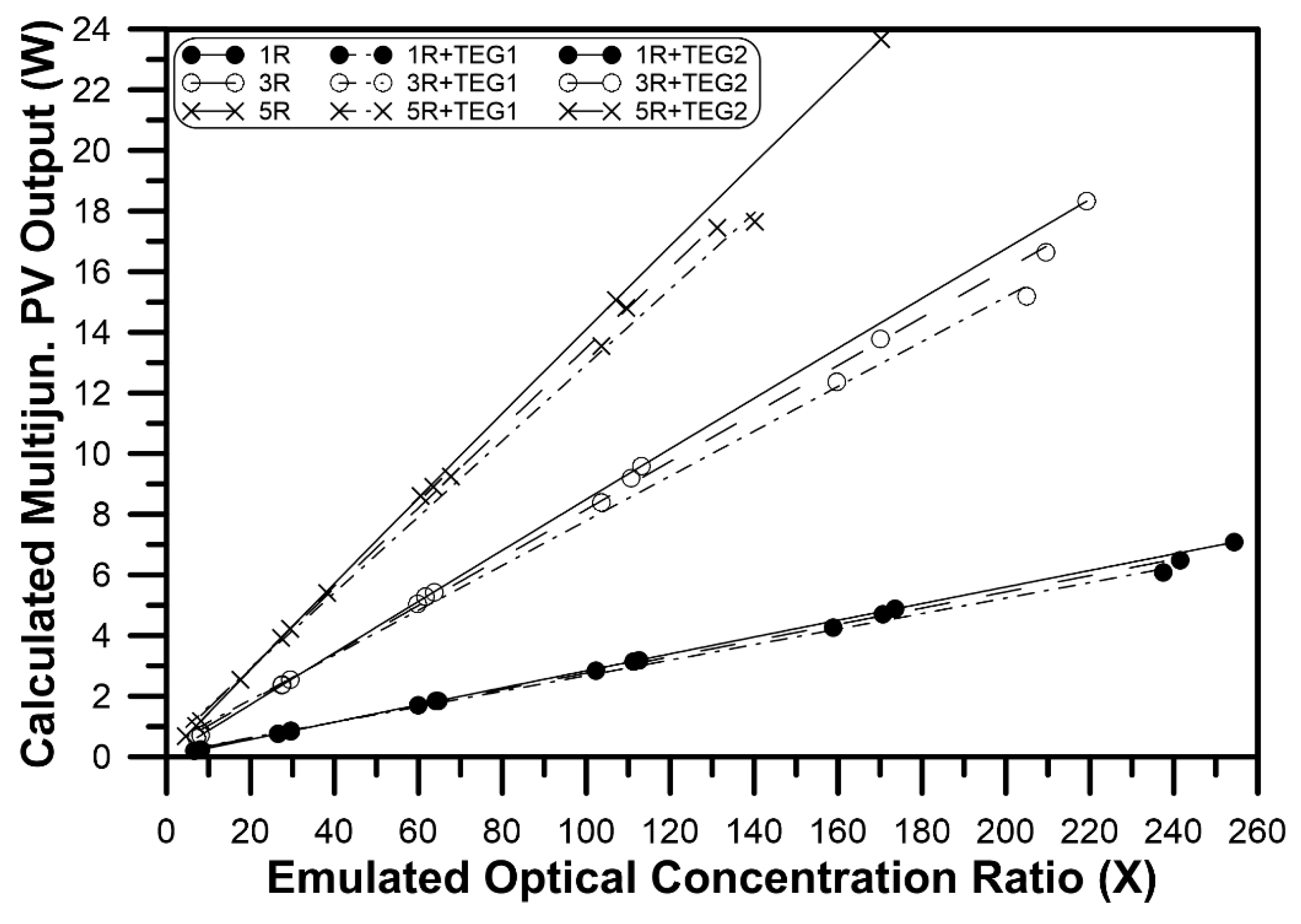
For the multijunction cells, a slight reduction of its output power was predicted in the case of one cell coupled to TEG1 and TEG2 as both TEGs were still able to absorb heat generated inside the cell. Adding more multijunction cells elevated the total system temperature, hence more reduction was predicted in the performance of PV systems compared to that of the PV only, as shown in
Figure 8. At emulated concentration ratio of 100X, the output power of the five cells of multijunction PV had a predicted reduction of about 8% and 4% for TEG1 and TEG 2, respectively. Cells attached to the TEG2 showed a higher output power than those attached to TEG1 because of the higher heat dissipation of TEG2 than that of TEG1. Such multijunction PV cells could withstand a concentration ratio as high as 180X for five cells coupled on top of the TEGs.
Performance of the LGBC silicon concentrator PV cell coupled to the TEGs, as well as those directly attached to the heat sink, are shown in
Figure 9. The electrical output power of Si cells coupled to TEGs showed a greater reduction than the output of the cells attached directly to the heat sink when increasing the emulated optical concentration ratio. Increasing the number of Si cells coupled to the TEGs elevated the overall system temperature, hence reduced the optimal optical concentration ratio, after which, output power declined. For five cells of Si LGBC coupled to the TEGs operating at emulated optical concentration ratio of 60X, the predicted output power reductions were about 32% and 18% for cells coupled to TEG1 and TEG2, respectively. This huge predicted reduction was because the temperature coefficient of efficiency of such Si cells was high compared to that of the multijunction cells.
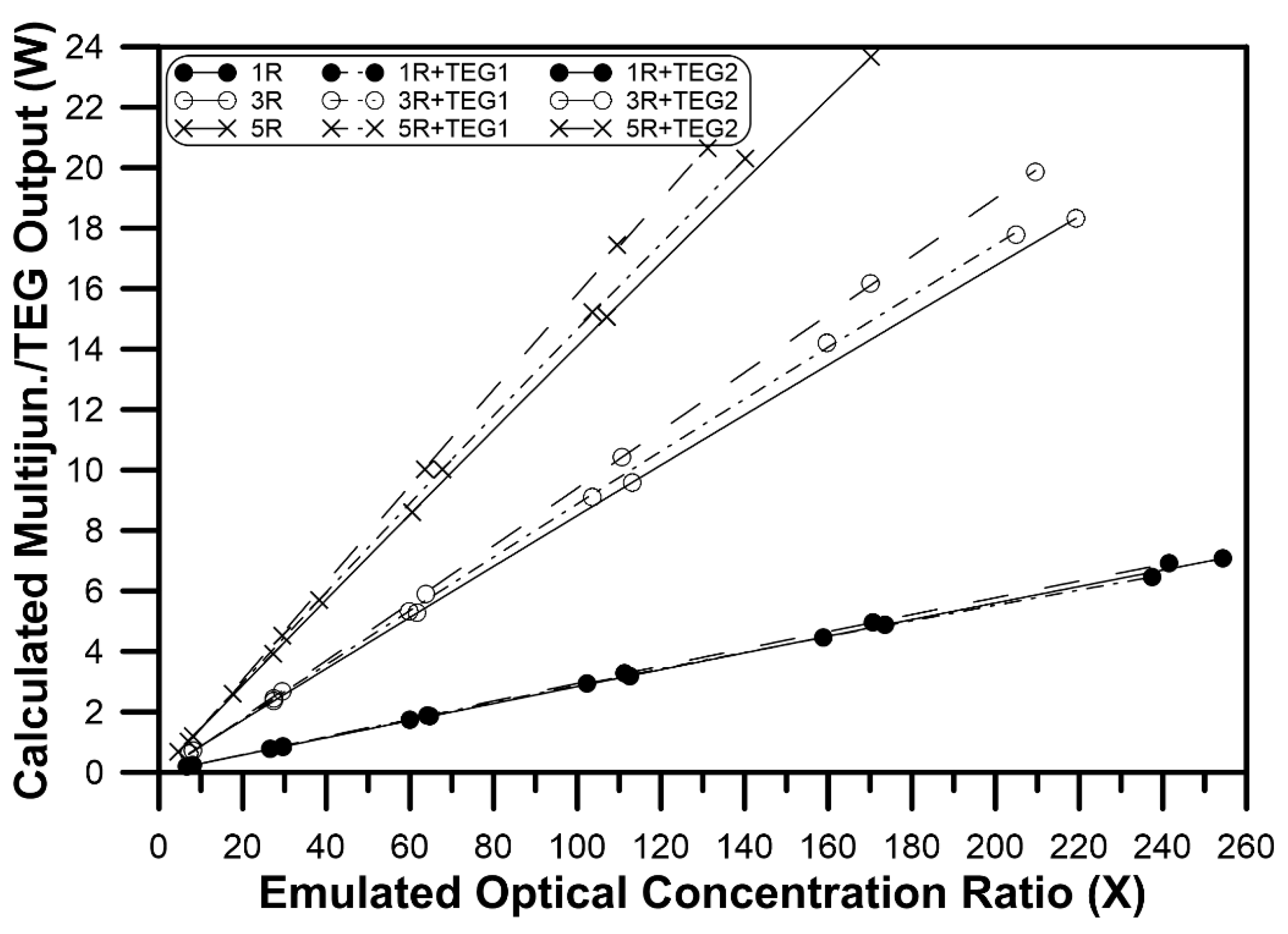
Multijunction cells coupled to a TEG total system output power (output of the PV cells plus output of the TEG module) is shown in
Figure 10. A minimal difference was predicted for the PV/TEG in the case of only one cell attached to either of the TEGs (symbolled “1R+TEG1” and “1R+TEG2” in
Figure 10) compared to that of the cells attached directly to the heat sink (labelled 1R in the same graph). Increasing the number of cells on top of the TEGs enhanced the total electrical output of the PV/TEG system. Increases of about 3% and 12% for the multijunction PV/TEG1 and the PV/TEG2 systems, respectively, were predicted compared to that of a PV-only system.
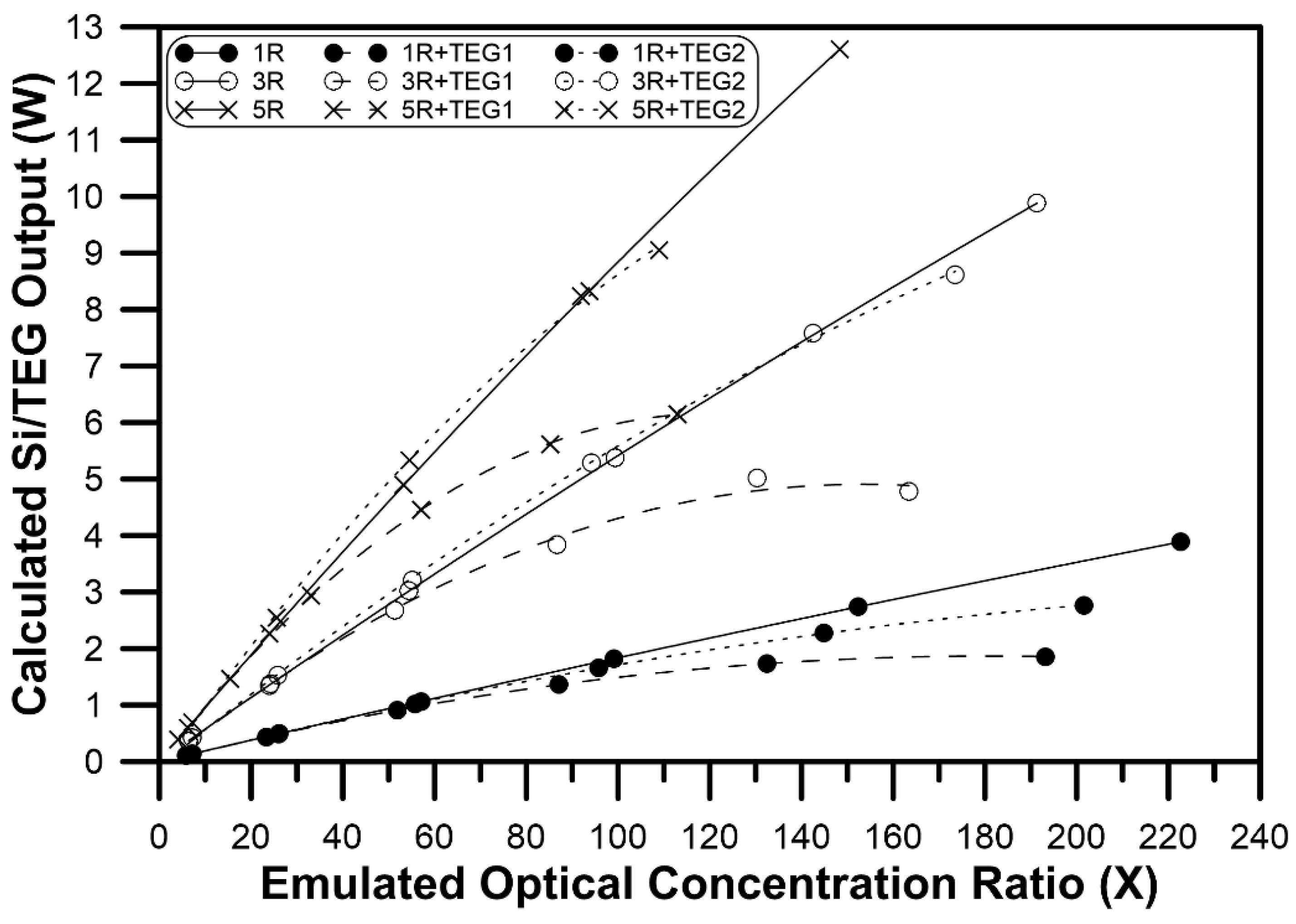
The predicted total system electrical output for a LGBC Si PV cell coupled to a TEG (PV cells output + TEG output) are shown in
Figure 11, which indicates that such Si PV cells are not appropriate for operation with the proposed PV/TEG system. An increase of about 6% in case of five LGBC Si cells attached to TEG2 and a reduction of about 16% in case of coupling to TEG1 were predicted compared to that of a system of cells attached directly to heat sink. This behavior was due to the high efficiency coefficient of temperature of Si cells.
5. Conclusions
In this work, a hybrid PV/T system has been investigated that incorporated a CPV cell coupled to a TEG. The TEG served as a passive cooling subsystem, and also for generating electrical power that was added to the total system power output. Two types of solar cells (a Ga0.35In0.65P/Ga0.83In0.17As multijunction device and a LGBC silicon concentrator PV cell) were proposed to be brought in contact with TEGs, and the operating conditions under concentrated solar radiation were emulated. These solar cells were assumed to be coupled to two TEG modules of the same type but having different number of junctions in order to investigate four different configurations of the proposed system.
LGBC silicon cells showed a sharp output reduction, especially with increasing the emulated optical concentration ratio, because of their high efficiency coefficient of temperature compared to that of the multijunction cells. The predicted output power reduction of five LGBC Si cells operating at an emulated optical concentration ratio of 60X were about 32% and 18% for cells coupled to TEG1 and TEG2, respectively, compared to that of the same cells cooled by heat sink only. Accordingly, the total LGBC-based system output power showed a trivial output enhancement for the five-cell system in the optical concentration ranged between 40X–80X in the case of coupling with TEG2 compared to the output when the cells were directly cooled by the heat sink only.
In contrast, the predicted total output of the multijunction-based system showed significant enhancement when the PV cells were coupled to either TEG.
At an emulated concentration ratio of 100X, the output power of the five cells of multijunction PV had a predicted reduction of about 8% and 4% for TEG1 and TEG 2 respectively. An increase of about 12% and 3% for the five-cell multijunction PV/TEG2 and PV/TEG1 systems, respectively, were predicted compared to that of multijunction PV cells attached directly to the heat sink.
The proposed PV/T hybrid system could be used successfully provided that: (i) CPV cells with a high PV efficiency and low efficiency coefficient of temperature, and (ii) TEG modules with high figure of merit are chosen carefully to construct such a system. Also, the operating optical concentration ratio and the covered area of the TEG have to be optimized to maximize the total output of the system.


