1. Introduction
Energy is predominantly the driving factor of human life and the economy of global countries. Henceforth, the research investigation in this area is highly critical and the need lot of time to invest for in-depth study [
1,
2]. Due to the fast depletion of the natural conventional resources, sustainable alternative energy sources, for instance tidal wave, solar, wind, biogas/biomass and hydro energy, must be tap together for developmental activities. Therefore, there is currently a tremendous increase in the lookout for sustainable and alternative energy sources to generate electricity. Wind energy seems to be a promising and potential alternative renewable energy source with its enhanced sustainability and eco-friendly nature. According to ‘Global Energy Outlook and the Increasing Role of India’, in the year 2040, the electricity generation capacity of India will be equivalent to what is produced by today’s European Union [
3].
Figure 1 shows a summary of electricity generation by selected region and its electricity generation by 2040. The Global Wind Report (GWP, 2018) mentioned that the wind energy is one of the cheapest forms of electricity in a number of markets. Has it is a cost-effective option for countries which have ever-growing power demands and distribution challenges with centralized grid system [
3].
The Global Wind Energy Council (GWEC) suggested that wind energy sector (both the on-shore and off-shore) supplies 300 GW of wind power capacity to come online by 2024 for global consumption. The global wind energy capacity increased with 51.3 GW in 2018. In spite of the fact, it is less than 2017 in about 4.0%; it is still a good achievement in wind energy capacity addition. From the year 2014, there is a 50 GW capacity addition occurring for every year though some markets behave differently. Thus, wind energy may contribute to electricity generation in India about 34,046 MW, which was 49.3) compared with all other renewable energy mix in the end of year 2018. By the year 2030, the wind power capacity is expected to generate 2300 GW power, fulfilling 22% of the global electricity demands. The report published by Global Wind Energy Outlook 2018 [
4] predicted the future of the wind energy industry until 2050. In 2018, 50,100 MW was added, which was lesser than that of the 2017’s capacity addition 52,552 M). It is viewed in 2018 as the consecutive year with increased new installations accounting to 9.1%, but this is lesser than the previous year’s data i.e., 10.8% growth in 2017. The global electricity demand met by 6% of the wind turbines installed in 2018. In
Figure 2, the cumulative production based on wind sources for the year 2018 shown along with the newly added capacity for the year 2018 [
4].
Figure 3 presents the overall baseline information of various settings, such as the new polices, moderate, and advanced scenarios. A global status report, published at the end of 2018, reported that global installed wind capacity was approximately 590 GW, which meant that Asia topped the regional market scale for the 9th consecutive year. It accounts for a whopping 48% of the added capacity (a total that exceeds 235 GW by the end of the year 2019) followed by Europe (over 30%), North America (14%), and Latin America and the Caribbean (almost 6%). In case of new installations, China retained the top position, though there was a contraction for two years. This was followed by US, Germany, UK, and India in respective positions.
Globally, the energy demands were 282.5 GW and 318.105 GW in the years 2012 and 2013, respectively. This denotes that there was a strong market growth of more than 19% and 12.5% in the years 2012 and 2013, respectively. However, this seems to be the lowest growth rate i.e., 22% and 21% of global electricity, when compared with annual average growth rate in the past decade. This is predicted to increase in the range of 8%–12% by the year 2020. The wind penetration level increased up to 10% in the year 2016, in alignment with the guidelines for international agreements on environmental commitment. By the years 2030 to 2035, the predicted saturation level is about 1.9 × 10
9 kW. The work by International Renewable Energy Agency (IRENA) titled ‘Global energy transformation: A roadmap to 2050 (2019 edition)’ inferred that by the year 2050, electricity would be the central energy carrier with growth up to 50% share from its current 20% share on final consumption. This would make the consumption of gross electricity double. The power demand across the globe (accounting to 86%) will be met by renewable resources-based power. Overall, the final energy will have two-thirds of contribution from renewable energy [
5]. According to the literature [
6], the current study focuses on the hypothesis subjects such as Wind Energy Conversion System (WECS) history, transformation of Permanent Magnet Synchronous Generators (PMSG), Finite Element Method (FEM) leveraging, Soft Computing (SC) applications, and the upgradation of Computer Aided Design (CAD) which looks to be a novel perspective as the first step. Generally, the wind turbine is moved by the wind pressure as in step-like method, though its design is different. In wind energy production, low (cut-in) and abundant (cut-out) wind speeds are labelled as risk potentials. On the basis of size and design parameters, the risk potential of every turbine is decided. Generally, the electricity yield of a wind turbine ranges from 3 to 25 m/s whereas high generation is examined once it crosses 10–15 m/s values. Each turbine has cut-in as well as cut-out values that are contingent on size as well as design parameters [
7]. Therefore, the wind turbine design plays an important role in energy production. Dai et al. (2019) stressed that, in recent years, the incorporation of wind turbine generators, such as Permanent Magnet Synchronous Generator (PMSG), and Doubly Fed Induction Generator (DFIG), in which the former is predominantly utilized in wind energy conversion system’s has been commonly seen, since it is cost-effective, highly reliable, and has flexibility in control [
7]. This paper aims to address the technical issues and fitness of WECS components and integration with electrical grid. Furthermore, it will explore the study of PMSG comprehensive comparisons with other topologies of generator. In addition, this paper will also shed insights on the gaps in research and areas to further enhance research, in the context of WECS.
2. A Brief Review of WECS
In 2004 article discussed wind engineering in general and wind power meteorology with special reference to turbine and generator technology. Further, they discussed the economics, which are involved in this regard [
1]. In a study conducted in 2007, the researchers stressed that the conversion of wind electricity is currently a green technology factor due to (1) structural design improvements, (2) design and manufacturing of blades, and (3) efficient power processing techniques, on the bases of power-electronics followed by new generator design, to achieve variable-speed operation [
8]. In 2013, [
9] discussed a list of possible changes in the methodology towards the implementation of utility-scale wind energy into the power grid and follow up in accordance to the updated research with their obtainable alleviation techniques.
Figure 4 disseminates the growth in size of wind turbines since 1980 and for predicted future prospects. The scaling up of turbines to lower cost has been effective so far, but it is not clear that the trend can continue forever [
10].
In 2012, [
11] developed a 5 MW baseline design in deep wind concept with more than 150 deep Darrieus-type floating wind turbine systems. In this research article, the technology used in previous works employing various generator types and manufacturers of large power direct drive wind turbines were detailed. In
Figure 4, the developments that occurred in the tower, blades, rotor diameter, power rating, and wind turbine hubs heights are illustrated. Amongst the available turbines, the 7.5 MW turbine seems to be the most powerful one with a 126 m rotor diameter. The global wind report published in 2012 cited the new Alston Haliade 6 MW turbine to be the world’s large turbine with a 150.8 m rotor diameter [
12]. In the future, the next-generation wind turbines are predicted to hold 20,000 kW capacity with a 250 m rotor diameter.
In 2010, [
13] investigated the power output density functions of different WECS for a variety of operating wind regimes with the help of a probabilistic approach. In 2007, [
14] conducted a review of information regarding global wind energy scenarios, performance, and stability of wind turbines, sizes of wind turbine, wake effects, evaluation of wind resourced, site selection, wind turbine aerodynamics, and challenges faced in wind turbines followed by wind turbine technology. Which is inclusive of control system, design, loads, blade behavior, generators, transformers, and grid connection. In 2014, a review of notable technical as well as environmental impacts of wind farms, wind power resource assessment techniques, control strategies, and grid integration techniques, were conducted [
15]. A comparative investigation was conducted using a Maximum Power Point Tracking (MPPT) control device in 2009 [
16] between the optimized configurations of passive wind turbine generators with that of the active ones that operate at optimal wind power.
3. Wind Turbine, Types, and Generator Technologies
In the past decade, there has been a tremendous growth observed in wind turbine technologies and that have resulted in the development of new-age wind turbine concepts. With developments in wind generator systems, cost-effectiveness of the systems has become the new mandate. In a wind power generator system, there is a tower which supports rotating as well as the stationary parts. The nacelle that has the generator in it, power converter, grid side step-up transformer, monitoring and control equipment are present in the stationary part. In 2014, [
17] developed a summary about compact and lightweight wind turbines along with the technical hindrances with special reference to Horizontal Axis Wind Turbines (HAWT). There are two broad categories of wind turbine technology at present; such has the HAWT and the Vertical Axis Wind Turbines (VAWT). The HAWT main rotor shaft rotates in alignment with the wind direction, whereas it is perpendicular to the ground, generator, transformer, converters, and other equipment in the case of the VAWT rotor shaft.
In HAWT, the nacelle is placed at the top position in the tower. The HAWT showcase better aerodynamic performance when compared to VAWT, due to which the former is largely deployed in large-sized offshore wind farms [
17]. According to [
18], there are approximately 8000 different components present in a typical wind turbine. This information is based on a RE power MM92 turbine with the blades’ lengths being 45.3 m and the tower height being 100 m.
Figure 5 shows the major components in a wind turbine and the share of the overall wind energy system parts cost. A direct-drive radial flux permanent magnet generator was checked for its suitability [
19] to act as a drive-train runner. FEM software was used to test the generator fitness, based on structural design (or in other terms the stability of the air-gap present between the rotor and the stator) as per PMSG. So as to deduce the differences in flux density and force along the periphery of the rotor. In this study, the researchers used a simple analytical model. Further, 2D magneto-static simulations where also used to check the validity of the analytical model by making use of FEM software carried out [
19].
According to the literature [
20], the induction and synchronous generator models are general candidates used to convert wind energy to electrical energy. In 2009, [
20] listed Danish wind power status and various topologies of other wind farm configurations. A classification was done by [
21] to differentiate the wind turbine technology schemes. To be specific, the different categories are Full Rate Converter Wind Turbine (FRCWT), PMSG, Fixed Speed Wind Turbine-Squirrel Cage Induction Generator (FSWT-SCIG), Variable Speed Wind Turbine-Direct Drive Synchronous Generator (VSWT-DDSG), Squirrel Cage Induction Generator-Wind Turbine (SCIG-WT), Full Rate Converter Induction Generator (FRCIG), Direct Drive Synchronous Generator (DDSG), Variable Speed Wind Turbine-Doubly Fed Induction Generator (VSWT-DFIG), Squirrel Cage Induction Generator (SCIG), Fixed Speed Wind Turbine-Permanent Magnet Synchronous Generator (FSWT-PMSG), Fixed Speed Wind Turbine (FSWT), Doubly Fed Induction Generator (DFIG) and Variable Speed Wind Turbine-Full Rate Converter Induction Generator (VSWT-FRCIG) [
21].
This segregation is done on the basis of power level, working principle, application type, and the usage in a number of commercial applications. The research and development in this area is still happening, and various novel configurations and advanced applications are in the testing stage. In 2006 compared different classification types and explained them in detail [
22]. In general, based on the working principle, three electric generators are considered as main types: induction, synchronous machines. Parametric which are associated with magnetic anisotropy and permanent magnets. The study further mentioned that the parametric generators in most cases be called as doubly salient electric generators [
22]. Since they are mostly equipped with doubly salient magnetic circuit structures. When classified according to the magnetic flux penetration, there are three types of permanent magnet generators present: transversal-flux, axial flux, and radial-flux machines [
22].
Since the efficiency provided is better, most of the high-power direct-driven wind power applications prefer low-speed and high-torque PMSGs [
23]. These are generally applied in a wide range of applications due to cost-effective Permanent Magnets (PM). According to the literature [
23], Permanent Magnets can provide high-power densities, higher efficiency, and chances of compactness which eventually results in the reduction of turbine size. The advantages of Permanent Magnet generators are when it excludes the exciter field winding, slip rings, and brushes in association with the capability to self-excite making option, so as to achieve good efficiency as well as the high power factor. In a standalone system, the PMSG has overloading and full torque capability, a highly competitive feature, due to which it is unique when compared to other traditional electrical machines. The PMSG is capable of self-excitation, another exciting feature which makes it the best option for operating at higher power factors and efficiencies. Further, PM machines possess the ability of overloading and full torque at zero speed, as well as at lower speeds [
24]. To be specific, the standalone power systems are utilized in the isolated areas. When compared with the traditional electrical machines, this is inevitably effective.
In 2009, [
25] studied the prospective site matching of direct-drive wind turbine models on the basis of electromagnetic design optimization of PM generator systems. In this study, a three-phase radial-flux PM generator was developed with a back-to-back power convertor. The study had a total of 45 PM generator systems which were designed, optimized, and grouped as a collage of five-rated rotor speeds in the 10–30 rpm range and nine-power ratings in the range of 100 kW to 10 MW, respectively. Following this, the study also determined the rotor diameter and the rated wind speed of a direct-drive wind turbine under optimum PM generator on the basis of the maximum wind energy capture design principle. This study also calculated the Annual Energy Output (AEO) with the help of the Weibull density function. At last, at eight potential sites, the maximum AEO Per Cost (AEOPC) of the optimized wind generator systems was calculated along with yearly mean wind speeds ranging between 3 and 10 m/s [
25].
In 2008, [
26] developed a concept of Permanent Magnet Generators Design. In this study, the researcher discussed the geared as well as direct-driven PM generators. Further, they also classified the direct-driven PM generators and the researchers dealt with various topologies of design aspects and unique nature in PM generators [
26]. In 2012, [
27] conducted a techno-economic evaluation of the basic assembly and magnetic topographies of the Salient Pole Synchronous Machine and Permanent Magnet Synchronous Machine. The study also provided the economic analyses of the machines that accompanied wind turbines.
4. Various Aspects of Comparison for PMSG’s
The design of electrical machines is important for any kind of applications. The basic design of an electrical machine involves certain procedures and analytical strategies. For calculation of magnetic circuit, electrical circuit, efficiency, insulation type, number of slots/poles combinations, winding dimensions, cogging torque analysis, control strategies, usage of materials, cost of products, thermal and structural design of electric machines, and manufacturing techniques etc. Finite Element Analysis (FEA) software can provide support for design and optimization tools to determine the best performance parameters. In 2008, [
28] elaborately briefed and further used a deterministic global mathematical optimization which became a vital tool in the processes of design. Several mathematical models and optimization techniques could handle such problems associated with multi-faceted design.
Figure 6 describes a complex range of ideas and significances of parameters for electrical machine design, analysis and characteristics studies, it has been simplified with partial adoption [
28]. The studies conducted so far in this research areas, and various viewpoints have been established [
28].
In 2012, [
29] conducted a general, as well as magnetic, analysis of various parameters, such as size, topology, voltage, magnetic field air-gap flux, weight, torque, losses, and efficiency between Permanent Magnet Synchronous Machines (PMSMs) and Conventional Salient Pole Synchronous Machine (CSPSMs) with the help of FEM.
Figure 7, the weights of active material and costs are compared, and analyzed. Based on the comparison, it is observed that the total weight of the active material in the PMSM is reduced by 6.55% more than the conventional salient pole machine. In
Figure 8, the losses at full load are presented [
27].
With the same output power generated by the Permanent Magnet used in the machine, there will be reduction in machine weight which eventually becomes lighter to produce and so it increases the efficiency. Once the investigation was complete, it was observed that the CSPSM expressed less efficiency when compared to PMSM’s. Further, when it comes to enhancement of magnet and semi-conductor expertise, the PMSMs reaped a cost-based benefit. Therefore, at the time of designing electrical machines, it is advised to follow their strategy in terms of machine efficiency and efficient use of energy [
29].
A seven type of systems such as variable-speed constant frequency (VSCF) wind generator system, PMSGDD, PMSG1G, PMSG3G, DFIG3G, DFIG1G, EESG_DD (Electricity-Excited Synchronous Generator with direct-driven), and SCIG_3G (Squirrel Cage Induction Generator with three-stage gearbox) has been compared. In this comparative study, the researcher made optimization designs for different wind generator systems in the range of 0.75, 1.5, 3.0, 5.0, and 10 MW [
30,
31]. The results inferred that the PMSG_DD was cost-effective when compared to EESG_DD systems due to the cost incurred in lower generator system and enhanced Annual Energy Production (AEP) per cost. When there is an increase in wind turbine, the cost spent on direct-drive wind generator seems to be reduced. However, when there is an increase in the rated power, there is an enhanced performance exhibited by the PMSG_DD system when compared to the EESG_DD system.
Following is the description for a single-stage gearbox drive train concept. Due to the low-cost generator system and high AEP per cost, the focus shifted to the DFIG_1G system which seems to be the best alternative. Further, when viewed from AEP per cost perspective, the DFIG_1G system seems to be the most cost-effective and is close to 1.5 MW. Following is the concept behind three-stage behavior drive-train. Due to the least cost generator system and high AEP per cost, the DFIG_3G system was considered as the best solution among other three wind generator systems. Additionally, in terms of AEP per cost aspect, more emphasis is given to the PMSG_3G system compared to the SCIG_3G system [
31].
Figure 9 compares all five various wind generator systems of respective manufacturers in a wide range of aspects.
When compared in terms of cost between a multi-hybrid PM wind generator system loaded in single-stage behavior and the direct-drive concept, the former seems to be cost-effective. When there is an increase in the size of the wind turbine, then the adoption of gear ratios may also widely vary. Based on the rated power levels, the optimum gear ratio may vary from 4:1 to 10:1. In the case of larger power ratings, the literature [
17] suggests making use of higher gear ratios would be better performance. In 2014 mentioned that PMSGs are predominantly employed by giants such as the manufactures as follows GE energy, Vestas, Siemens, Gamesa and Goldwind. The stator of the PMSG is wound where the rotor is present with the PM pole system and may possess salient cylindrical poles. At most of the time, the low-speed synchronous machines project the salient-poly type with predominantly numerous poles. One can develop a direct drive system based on a synchronous generator with an ideal number of poles (a multi-pole PMSG). Some common types are transversal flux machine, axial flux machine, and the radial flux machine. The PMSG machine expressed highest the efficiency in an induction machine since the excitation was supplied excluding any energy flow. However, it is difficult to manufacture the PMs, whereas its inventory is cost-consuming too [
17].
The long-term-unaddressed issue comes with the mandate to maintain the rotor temperature less than the magnet’s threshold temperature. This may further be influenced by the magnetic material’s Curie point and the binding material’s thermal criterion in the case of power metallurgy composites. In turn, the synchronous process generates the issue according to the start-up, synchronization, and voltage regulation [
32]. In 2011, Sandra Eriksson et al. performed an excellent comparison of direct-driven PMSGs. A total of six different-range generators were compared among each other [
33].
Figure 10 clearly depicts the considerations of various factors with respect to the fixed and variable parameters for different ranges of generators.
In 2013, [
34] compared three configurations such as gearless-drive Permanent magnet induction generator PMIG-WECS, gearless-drive PMSG, geared-drive squirrel-cage induction generator (SCIG), and in the index every system was allocated with a number such as 1, 2, and 3 to position itself in the rank in accordance to other two systems. According to
Table 1, the geared-SCIG system seems to be prominent in 61.5% of the indexes, while at the same time 38.5% of indices where dominated by the gearless-PMSG system. There was a 60% similarity in advantages between gearless-PMIG and gearless-PMSG. Therefore, the geared-SCIG system exists in alignment with the number of indexes. However, there is a domination of gearless-PMSG in the three top priority indexes such as generation efficiency, Operation & Maintenance (O&M) cost, and the duration of failure behavior. Further, there was a domination of geared-SCIG in the four top priority indexes such as kWh production at low speed, frequency of failure, generator O&M cost, and capital cost. In order to achieve the results with best accuracy, the weight of an index should be considered as per the order. Among the different configurations considered for the study, the results concluded that the gearless-drive PMSG-based and geared-drive SCIG-based systems seem to be the most desirable solutions. From
Table 1, it is identified that the gear less PMSG is the only machine, which has the best option in efficiency, as there is no gearbox and copper loss [
34].
In 2010, [
35] with the field-circuit method for rapid calculation of load characteristics for stand-alone PM synchronous generators (PMSGs) that were developed with various rotor structures. The study results were compared with load characteristic calculations and results. The field-circuit method was defined, and utilized to determine the load characteristics of PMSGs with surface-mounted, inset or interior mounted permanent magnets and with inner or outer rotors [
35]. In a comparative study conducted 2013, two PM generator types such as radial flux PM (RFPMG) and axial flux PM (AFPMG) generators were compared. To compare the generator performance during mechanical energy storage, the study measured the output powers of both RFPMG and AFPMG [
36]. Results shown in
Figure 11 and
Figure 12, concludes that there was a better performance exhibited by RFPMG when the machine’s electrical parameters were in very similar condition and in relatively small power applications. It was inferring that the RFPMG has fewer copper, core, and rotor losses with respect to the varying generator and wind speed when compared to AFPMG [
36].
5. Different Design Perspectives
Designing PMSG has several challenges, which make it complicated when compared to conventional machine design procedure. The combination called ‘Slot and Pole’ poses various other challenges, which include reducing eddy current losses and cogging on permanent magnets. In 2013, [
37] a technique was proposed to improve the air-power gap apparently transferred under the constraint of tangential stress using analytical optimization algorithms. The processes of optimization have been optimized for expressions that are relevant for the design of main variables, external derivations, and operational restrictions for the formulation of mathematical derivations.
In general, terms, during PMSG design, the optimum design includes various mandatory requisites, which are to improve profitability, and mitigate utilization of material to reduce cost and weight [
38]. In addition, the design considerations should also take into account availability, high reliability, and low serviceability and maintainability for TC Ia that is wind class [
38]. Furthermore, the utilization of gearless or semi-geared drive machines improves efficiency and reliability of wind power generators. Additionally, such requisites are associated characterization of compactness in terms of weight and dimensions. In addition, during the design of PMSG, the mechanical forces and voltage waveforms are quite imperative in several applications [
38].
The design of machines is generally concerned with the electric and magnetic circuits; however, there are several losses which are measured using empirical equations [
39]. In 2011, [
39] explored the various design aspects concerned with the radial and axial field of synchronous machines with permanent magnets. In addition, the analysis of three fractional-slot and concentrated winding permanent magnet synchronous machine topologies are suited especially for specific applications [
39]. According to a study [
40], which explored the performance of wind power generators fitted with external permanent magnet rotors. The authors analyzed the FEM and electromagnetic results that examined the turbine characteristics and variations of the nominal wind speeds; various systematic methods were employed in previous research. For the calculation of the electrical characteristics, such as synchronous inductance, Electromotive force (EMF) constant, and phase resistance, an electromagnetic analytical and magnetic field distribution method was applied. In this study, a d-q model coordinate transformation theorem was employed for the analysis of performances. In addition, FEMs and curve fitting are used for the analysis of core losses [
40]. Furthermore, a dissertation [
41] presented a transformation theorem that developed a technique for the optimization and design of machines mounted with Surface Mount Permanent Magnet (SMPM), as impacted by mechanical loads, energy source, thermal effects, and state-of-the-art developments in manufacturing and material capabilities. A method was proposed for the design and development of cage rotor induction machines that can be optimized for better performance. Both genetic algorithm GA and particle swarm optimization (PSO) were used for optimization of the machines. Different integrated methods were applied and the Electromagnetic-Thermo-Mechanical method was used for the fabrication of Surface Mount Permanent Magnet (SMPM) machines [
41]. An iron-less brushless permanent magnet machine was proposed and designed in 2013 [
42] for the design and optimization of generator applications. The proposed approach constituted a dimensioning technique that involves comprehensive geometric techniques; both electrical and magnetic methods were used followed by the use of a detailed 3-D finite element (FE). In addition, the machine configurations used were both circular and rectangular designs, and were compared against each other. Furthermore, the performance of ironless stator designs configurations and the effectiveness of materials used were compared [
42]. Tangential magnetic flux and stator concentric windings were incorporated in wind power generators in 2009 [
43] with the rotation frequencies of 75–300 rpm. The parameters associated with the developed generators were depicted in the research. The intention of the previous research was to analyze the working of synchronous generators fitted with permanent magnets, which is in line with the concept of mitigating the problem of magnetic field distribution that was studied separately using FEM. During the development of such models, as given below in
Table 2 and
Table 3 the following parameters to acquire synchronous machines should be considered and varied:
In addition, the following parameters should be considered for mathematical simulation.
In 2012, [
44] examined and designed PMSG using FEM simulation software that involves low speed three phase generators associated with external rotors. The aim of the research paper was to obtain sinusoidal voltages that are induced in stator windings which are espoused magnetization and arrangement path of permanent magnets within the rotor structure [
44]. Again in 2012 [
45], used the multi-physics approach for the design and development of a 10-MW doubly fed induction generator (DFIG). The optimal design and analyses were considered for the operation of direct drive of wind turbines with a conversion that has reduced size. In 2005, [
45] performed a study that comprised of PMSGs that were used in wind power generation systems that are small. The output voltage was examined using FEM wherein both no-load and load conditions were considered. The influence of shapes and magnetic dimensions was examined. The previous research is a novel study wherein the outcomes of FEM were analyzed that revealed the PMSG’s cogging torque frequency was influenced by number of poles and stator slots. However, the performance was influenced by factors such as magnet dimension, air-gap length, and cogging torque magnitude [
46]. Research conducted by [
47] (2008) depicted the design, prototyping, and analysis of relatively small and cheap axial-flux three-phase coreless permanent magnet generator. In the previous research, the FEM approach was used for the measurement of equivalent circuit inductances. In addition, the end winding inductance calculation and equivalent resistance of eddy-current loss where calculated using traditional methods. In 2002, [
48] proposed a method for performance improvement using soft magnetic composite inter poles in drive permanent magnet machines. Several factors such as suitable pole arc shapes, magnet dimensions’ influence, material usage efficiency, and labor costs where considered. In 2011, [
49] examined the design considerations of double rotor radial flux permanent-magnet wind generators in terms of the mechanical and electromagnetic non-overlap air-cored (ironless) stator windings. The developed model was examined using finite-element analysis. The results of the analysis revealed that the electromagnetic design determines the mass, cost, rotor yoke dimensions, and leakage flux paths. In 2012, [
50] examined the axial flux PM generator performances using wind turbine characteristics and electromagnetic field. The analytical approach could mitigate the analysis time required when compared with the FEM that is three-dimensional, which could use for the calculation of performances in the preliminary design phase. In 2010, [
51] proposed and developed an optimal design high-speed DC generation system that uses a slot-less PM machine. In the previous research, the researcher used soft magnetic composite (SMC) stator yoke and a controlled rectified fitted to the stator winding [
51]. In [
52] (1997) further examined the multi pole PMSG with the radial field. PMSG machines have been used as direct-coupled grid-connected generators with ratings between 100 KW and 1 MW. However, the previous research revealed that the poles that are between 100 and 300 are found to render better performance in terms of efficiency and reactance. The stator and rotor section design present the suitable pole and power number. Standard ferrite magnet wedges are used in the rotor sections. The stator sections however are made up of E cores with a single rectangular coil in each core. The researcher also developed a lumped-parameter magnetic model that permits the calculation of machine parameters in a rapid manner [
52]. In [
53] (2007) examined the direct-coupled an Axial Flux PMSG (AFPMSG) that is appropriate for a wind turbine system. Furthermore, the researcher used horizontal-axis and vertical-axis wind turbine generator systems. FEM analysis was undertaken for the analysis of the AFPMSG magnetic flux density distribution. The results analyzed were compared with the proposed machine configuration wherein the voltage from the output line was found to be of sinusoidal pattern. AFPMSG design feasibility was confirmed using a prototype generator [
53]. In 2010, [
54] further displayed an Axial-Flux Permanent-Magnet Generator for Induction Heating Gensets whereas ([
55], 1997) and ([
56], 1994) proposed a straightforward approach for the design of brushless permanent-magnet machines; the results are supported by several analytical results. The main difference between sine wave and square wave motors are detailed and described in terms of EMF, self-inductance, flux density and so on. A stage by stage method is involved with the design of computer-aided systems which are elaborated in detail. The previous research detailed the information such as torque, shape, magnet poles and phases, slots, poles, teeth, energy and co-energy, magnetic circuit concepts, yokes, basic relationships, magnetic materials, flux linkage and inductance, influence of stator slots, tooth flux, back-EMF, need for the field analysis based design FEM, cogging torque, series and parallel connections, and loss modeling [
56]. Though machines achieve infinitely, the core of the machine that operates under unsaturated conditions and deep rectangular slots are not appropriate and not suitable for the design of today electrical machines with non-linear materials. The machine’s performance should be predicted with great accuracy to solve non-linear equations which is expressed in terms of the Magnetic vector potential. The irregular machine geometry confirmation makes the analytic method configuration challenging. Hence, there is a need to use appropriate field computation, and modeling techniques utilizing electromagnetic fields such as the energy minimization. Includes, differential/integral functions, variational method, discretization, shape functions, stiffness matrix, 1D and 2D planar and axial symmetry problem and computation of electric and magnetic field intensities, capacitance and inductance, force, torque, and energy for basic configurations of electrical machines [
57].
In
Figure 13, various electromagnetic analytical methods are illustrated. Every method contains a set of advantages as well as disadvantages. In this scenario, the finite elements were found to be robust in nature to conduct general electromagnetic analyses [
57].
6. Consideration of Losses Calculation for PMSGs
One of the important design factors discussed in this study is the determination of losses in PMSGs. In 2010, published a model with an elaborate loss computation and calculation method with updated analytical loss calculation. In this model, conventional losses, for instance, stator core iron losses, ventilation losses, I
2R losses, and other detailed losses like stator end region losses, were discussed. However, being a separate engine, the cooling caused by the bearing friction and the losses incurred via excitation system were not considered. The components which were lost are discussed here in detail [
58].
(a). Iron Losses
Excluding the stator and rotor windings, there seemed to be losses in eddy current as well as some more losses in entire metallic parts, which can be segregated as follows.
Iron losses in (teeth and yoke) stator core which included the impact of rotating fields and harmonics.
Eddy current losses on pole shoe surface because of the tooth ripple pulsation and stator winding armature reaction magneto motive force.
Eddy current losses in the stator clamping plates.
Eddy current losses in the stator clamping fingers.
Eddy current losses in the stator core end laminations.
Eddy current losses in external metallic air guides.
(b). Winding Losses
Various types of losses in stator, rotor, and damper windings are inclusive in winding losses
Stator winding copper I2R losses.
Rotor winding copper I2R losses.
Due to the tangential slot leakage field, the occurrence of eddy current losses in the stator winding.
Due to the radial slot leakage field, the occurrence of eddy current losses in the stator winding.
Due to end leakage field, the overhanging of the circulating current and eddy current losses.
Damper winding losses due to tooth-ripple pulsation and the stator winding armature reaction magneto-motive force.
On the basis of statistical measurements, the rest of the losses were calculated with basic equations.
(c). Ventilation Losses
Ventilation losses segmented further into following parts
In 2011, a study [
59] of extreme excellence was conducted by on electromagnetic losses which were incurred in direct-driven PMSGs. Using electromagnetic model, the solutions were obtained from FEM. By utilizing a MATLAB-driven model, the researchers performed the simulations. The results obtained inferred that the iron and copper losses were completely based on the rated voltage and rated current. In terms of a fixed output power, the experiment achieved larger machine volume with an increase in rated voltage. Further, higher frequency and increased iron loss were observed in parallel to decrease rated current and reduce copper losses. At the time of simulations, the generator losses were determined for various wind speeds, using which the loss distribution was calculated. Furthermore, they tested an analytical model to predict the eddy current losses in PMSG rotor magnets by feeding a rectifier load. The eddy current loss achieved during time stepping resulted in the coherence of 2-D FEM and coupled-circuit when performing the investigation. In 1997, conducted an experiment and designed losses for the model of a 1 MW machine design prepared in alignment with the parasitic losses. These were stator back-iron reluctance, rotor and stator slotting, rotor reluctance, stator back-iron reluctance, stator module weld loss, rotor eddy-current loss, stator beam loss, the polygon effect, and stator structure cage loss [
60]. In 2014, [
61] experimented on eddy current losses in PMs of surface-mounted magnet synchronous machines. This study introduced a true analytical method on the basis of magneto-dynamic problem of a conductive ring. The results were obtained and compared with the information retrieved from 3-D FEM analysis. In the analytical model, the effect of the width on magnet loss was considered. The axial effect was considered via a correction coefficient. In the comparison executed, the researchers included impact of the circumferential segmentation, instantaneous losses, effect of the frequency on magnet losses, and induced current density. Through stressing the criticality of the skin effect and magnetic reaction due to magnet currents, this analytical model yielded an accurate measurement of magnet eddy current losses [
61].
7. Faults and Protection
At the time of designing PMSGs, researchers must be considered for the chance of fault occurrences and protection schemes methods. In 2013, [
62] listed the influence of asymmetrical magnet faults upon PMSG rotors. Mechanical looseness, eccentricity, and damage in any one magnet are the most commonly found attributes that result in rotor faults. Further, the rotor eccentricity is caused by unequal distribution of static, dynamic, or mixed air-gap. In the presence of static eccentricity, the air-gap seems to be the least and positioned as per the stator. On the contrary, in the case of dynamic eccentricity, there seems to be no coincidence between the rotor’s centers and the center of rotation. Therefore, the minimum air-gap position rotates in line with the rotor. There are notable reasons behind the cause of eccentricities such as looseness, incorrect assembly, load unbalances, misalignment, and sometimes the bending of the rotor. At the time of analysis, the study conducted series as well as parallel-connected windings. In order to quantify the demagnetization in a single magnet, the study defined the faulty severity factor. As per the study investigations, one can conclude that, for a generator where all windings are series-connected, the induced EMF value gets decreased due to the demagnetization of a single magnet. Likewise, if the load is a resistive type, the current also may decrease. Therefore, one may not be able to identify the frequency components which are in association with the fault whereas one can observe only the decreased total flux linked to the windings [
62]. In 2012, Rodrigues et al expressed his ideas on direct or indirect lightning strokes after thoroughly reviewing the over-voltages and electromagnetic transients [
63]. The transient behavior can easily be explained via the lightning protection of the wind turbines accurately, for which the modified version of EMTP (Electro-Magnetic Transient Programme) was utilized. In this study, the researcher adopted a case study model in which two interconnected wind turbines were used so as to study the direct lightning stroke to the blade or the lightning strikes which happens in the soil near a building. Further, this study also conducted a holistic computer simulation in addition to EMTP-RV [
63]. Investigation in 2011 [
64] which evaluated the fault conditions and identified efficient fault ride-through and protections schemes in electrical systems of both small-scale (land) and large-scale (offshore) wind farms. In their study, the researcher considered two variable-speed generation systems such as PMSGs and DFIGs. After discussing the protection issues associated with DFIGs, the research proposed a new protection scheme as well. Following this proposal, the protection scheme options for fully rated converter and direct-driven PMSGs were analyzed and simulation results were compared.
The development in magnetic materials and its impact on the electric machine design investigated (2007) [
65]. In addition to that, few potential faults were also selected using a fault-tolerant system design. Two fault types may occur in the system, of which the electromagnetic faults are as follows:
Winding open circuit;
Winding short circuit (phase/phase);
Winding short circuit at terminals;
Turn-to-turn fault in a phase.
The power converter faults are listed herewith
Power device open circuit;
Power device short circuit;
DC link capacitor failure.
One should focus on development of a fault-tolerant system, if the operation needs to be continued even in the presence of faults, if any. In this design, every phase should have a stand-alone single-phase PWM inverter that has a modular system in which the modules are isolated by every phase fault. When a module has less thermal interaction or electrical/magnetic interactions, then the system is likely to proceed with the operations excluding the faulty phase [
65].
By 2012, inducted a rotor core design and FEA simulation, to diminish the mechanical stress put upon the core bridge. After considering rotor speed variations, the researcher performed the mechanical transient analysis. The experimental result was presented for the S-N curve (S-N curve is deduced from material test data) of rotor care material so as to assure the validity of the model against fatigue failure [
66].
10. Soft Computing Technique Based Optimization Used for PMSGs
There are two critical issues that influence an electrical machine’s optimal design considering the usage of FEM, the computation time from FEM simulation, and the different parameters concerned with the electrical machine. In the present day scenario, the use of soft computing techniques-based optimization has gained momentum owing to the use of the statistical analysis with multiple correlation coefficients and moving least squares (MLS) approximation as proposed (2007) which are compatible with the electrical machines [
73]. In general parlance, the process of optimization includes several computations which are all dependent on parameters; the effort of computation is very minimal when compared to the time that is saved. Such a method is assessed by the same application to synchronous machine’s optimal design. The results of such analysis reveal the increase in the torque per weight ratio by 13% when compared with the results that are acquired from traditional optimization techniques [
73]. In 2010, [
74] used the Fuzzy and FEM method for the analysis of the comparison that includes leakage field analysis witnessed in the electrical generator. The process of leakage field analysis is performed by developing a fuzzy model of the generator with the technology called adaptive neuro-fuzzy inference system (ANFIS). In this regard, the researcher performed a comparative evaluation on fuzzy model and FEM model wherein a good correlation was found to be present between them [
74]. Furthermore, a study (2008) [
75] revealed the new and novel approaches towards automating optimization processes that are manual, and examined the implementation obstacles that are witnessed by the engineering community. Based on the effort for design evaluation and the degrees of freedom viewpoints, engineering design optimization was subjected to classification. In the previous research, the researchers presented a holistic view on the various design optimization approaches. Furthermore, the major challenge witnessed was scalability for the techniques of design optimization considered in the study. Large-scale optimization requires effective algorithms such as swarm intelligence and a considerable computing power [
75]. However, 2001, [
76] proposed the use of a neural network in comparison with the Finite Element Technique (FET) based sensitivity analysis for the optimization of permanent magnet generators. In 2012, [
77] further identified the challenges that were witnessed during design optimization for minimizing or maximizing the fitness function which positively influence the design purpose. Genetic algorithm which is incorporated in the optimization technique that is population based does not consider certain inferences, such as the magnet, copper, and magnetic laminations, and raw active materials. The main intention towards the reduction of the fitness function is based on the cost of energy that is generated by the system which further accounts for the variables that are uncertain in nature [
77]. In 2009, [
25] further explored the use of direct-drive PM wind generation system optimum design models wherein the PM was designed and developed using enhanced genetic algorithm with a PM generator fitted with 500 kW direct drive wherein the minimization of the active material cost tends to improve the design optimization effectiveness.
In 2009 used the concept of direct-drive PM wind generation system optimum design models in which the PM is developed using an improvised genetic algorithm along with a 500 kW direct drive PM generator; this actually reduces the cost of generator active material which further illustrates design optimization effectiveness [
25]. Furthermore, [
78] (2007) proposed a novel approach for the design of electrical rotating machines wherein a rational solution of predesign was done by integrating exact global optimization algorithms and analytical model. However, prior to developing an extensive prototype, validation of previous solutions should be performed using FEM. The purpose of the previous research was to extend the accurate global optimization algorithm through the introduction of an automatic numeric tool. Such a novel technique is used in resolving rationally the design problems. Furthermore, several examples were evaluated to examine the effectiveness of the novel technique [
78]. In 2008, [
79] further established a new hybrid machine with 36/24 pole outer rotor permanent magnet (PM) that is directly coupled with a wind power generator. For effective control of the flux control, two excitation (PMs and DC field windings) hybridization in the double-layer stator is utilized. This result in constant output with wide range of speeds and a load varying where examined. In 2001, [
80] further used genetic algorithms wherein a new algorithm called orthogonal genetic algorithm along with quantization/quantification for global numerical optimization was used with continuous variables. Furthermore, a quantization technique and orthogonal design were used for the development of a new crossover operator; this crossover operator generates representative sample points which are small, however are a potential offspring. Such a proposed algorithm solves 15 benchmark problems with 30–100 dimensions belonging to the local minima [
80]. It was 2005 arrived at new dimensions in this research area of evolutionary computation and structural design [
81]. Furthermore, [
82] (2008) examined soft computing (SC) techniques associated with the design of engineering concepts. Through the inspection of soft computing methods, techniques, and their competence, to further address the high complexity issues and design tasks, the researcher reviewed Fuzzy logic (FL), artificial neural networks (ANN), and Genetic Algorithms (GA) [
82]. In 2012, [
83] further made an overview to compare research that was conducted to optimize the parametrization of machining process of modern and conventional machining. Following are the most important techniques used: genetic algorithm (GA), particle swarm optimization (PSO), simulated annealing (SA), artificial bee colony (ABC) algorithm, and ant colony optimization (ACO). Amongst the aforementioned algorithms, GA is widely applied in the literature [
83]. In 2004, [
84] proposed a new solution called the multi-agent genetic algorithm (MAGA) which is an integration of the genetic algorithms and multi-agent systems to solve the problem of global numerical optimization. In 2008, [
85] further proposed a disagreement versus randomness in the various SC techniques. In 2011, [
86] further reviewed the state-of-the-art research developments associated with the use of soft computing techniques used for the optimization of problems associated with design, planning, and control in the field of sustainable and renewable energy. Furthermore, several soft computing methods were reviewed and presented regarding the current state of the art in computational optimization methods applied to renewable and sustainable energy, wherein a vibrant visualization of the state-of-the-art research progresses was proposed [
86]. It is important to generate random numbers using soft computing methods, as random numbers are used during the beginning of the estimation or during the processes of learning and searching. When compared between simultaneous randomness consideration and opposition and pure randomness, it was revealed that the former is better than the recent results acquired from evolutionary algorithms, neural networks, and reinforcement learning. To further increase the performance of soft computing algorithms, it was revealed that opposition-based learning provides an inclining effect. This was experimentally and mathematically proven that SC has better merits when applied to improve the differential evolution (DE) [
86]. In 2010, [
87] also presented the Genetic algorithm (GA) with memetic algorithm and MADS (Mesh Adaptive Direct Search) for the optimal design of an electric machine. To acquire an effective optimal design of an electric machine with longer computation time and many local optima, the previous research proposed a hybrid algorithm to acquire global optimum. To maximize further Annual Energy Production (AEP), the prospective algorithm was referred. By 2006, [
88] classified the modelling and optimization techniques for process problems shows in
Figure 16, which displays the conventional and non-conventional optimization techniques and tools used in this regard.
To further conclude, it was deemed that MADS is combined with GA as an effective computation time reduction method for optimal PM wind generator design and is considered over other parallel computing methods [
89]. Further offered a type of multidisciplinary design and optimization (MDO) of a diffuser for an incompressible and steady magneto-hydrodynamic (MHD) method. The design problem can be resolved using GA-based programme that is optimized with the FEM based MHD simulation technique for which least-square FEM was used and developed in later research [
89]. In 2017, [
90] presented about Multiple Criteria Decision Making (MCDM) concepts and has been used for economics analysis. Similarly, this concept can be used for lifecycle cost analysis of machine design [
90]. In (2002) [
91] presented the non-dominated sorting GA to mitigate the performance related problems wherein the performance was analyzed through the comparison of the results from the other four algorithms. Further discussion was performed on the multi-objective optimization process solution using evolutionary algorithms, wherein the findings of the research revealed effectiveness against analytical and electro-magnetic problems [
91]. Furthermore, [
92] (2001) displayed an approach that was used to design PM for wind power applications wherein the approach was made up of two phases: preliminary design stage and optimization stage. In 2008, [
93] further examined the use of Differential Evolution (DE) and Particle Swarm Optimization (POS) Algorithms with technical analysis. It was ascertained that the Artificial Bee Colony (ABC) algorithm could be used as an innovative swarm optimization algorithm with fine results of numerical optimization.
Furthermore, [
94] (2011) proposed an enhanced algorithm called the fast mutation artificial bee colony algorithm (FMABC). In 2012 proposed an improved ABC algorithm, which was used to solve numerical optimization issues, which further improved the capability of the ABC algorithm’s exploitation feature. An alternate search mechanism and a varying probability function were proposed by the previous researcher. Seven numerical optimization problems were tested on the enhanced ABC algorithm [
95].
In 2012, further utilized genetic algorithm (GA) for the achievement of an optimal design for an axial-flux PMSG (AFPMSG) [
96]. In 2009, [
97] proposed an approach based on a numerical optimization algorithm wherein a generalized receding horizon control of fuzzy systems was proposed. To further resolve generic fuzzy dynamic systems’ optimal control problem, a numerical method was developed. Fine optimization was developed in the previous research.
The researcher made a thoughtful understanding of soft computation techniques in the electrical engineering field applications, with integrated pseudo-code operational summaries [
98]. In 2010, [
99] considered population-based algorithm and its application to solve numerical optimization problems. In certain cases, there are complexities in computing search problems which is associated with high dimensionality of search spaces. Until there is an employment of appropriate approaches, a search process could reduce effectiveness and increase cost. The use of nature inspired algorithms could tackle such difficulties. For example, fish schools tend to increase the mutual survivability since a large number of constituent individuals are deployed.
In 2008, first to introduce a method that searches high dimensional spaces that consider account behaviors that are obtained from fish schools. The derived algorithm—Fish-School Search (FSS) was made up of three operators: feeding, breeding, and swimming. In a cumulative scale, these operators tend to afford the evoked computation: (i) wide-ranging search abilities, (ii) automatic capability to switch between exploitation and exploration, and (iii) self-adaptable search process for global guidance [
100].
S.L. Ho et al. (2006) examined the use of particle swarm optimization (PSO) methods wherein the previous research considered several variables such as age; new strategies were figured out to examine the optimum particle solutions, the original formula for velocity updating, and intensified search phase integration with enhanced PSO method. The findings of the previous research revealed that the proposed method contains a refined ability to perform a pinpointing search and the overall global ability improved when compared to traditional PSOs [
101].
It was [
102] offered the use of support vector machine (SVM) classifier for the detection of broken electrical induction machines. Furthermore, the previous researchers also considered the analysis of Gaussian, linear and quadratic kernel function as opposed to the error rate and the support vector numbers. The findings of the previous researchers revealed the successful detection of broken bars in different situations wherein there also evidences fast, precise, and robust load changes which tend to qualify for the right use of such techniques in real-time online applications in industrial drives.
Furthermore, in 2002 proposed a tabu-search algorithm to identify multi objective optimal design problems’ pareto solutions from which there is a utilization of the contact algorithm to assess the previous aspects. During the initiation of the iteration cycle, identification of the new current points, fitness sharing function, and ranking selection approaches are introduced. A more detailed explanation of the numerical results is displayed in the previous research to highlight the power of the proposed algorithm to ensure that there is uniform sampling performed which yields Pareto optimal front of the multi-objective design problems. Furthermore, effective execution strategies for the proposed algorithms were also displayed [
103].
In 2011, further displayed the Improved Discrete Particle Swarm Optimization (IDPSO) searching technique, which is applied on the head of an electromagnet and for the optimization of the magnetic field gradient. For the previous research, COMSOL software was used for the measurement of the magnetic forces and field. The aim of the optimization algorithm is the search of optimal pole shape geometry in a refined manner, which results in the distribution of the homogeneous magnetic field with the desired holding force in the specific area of interest [
104].
Furthermore, [
105] (2007) displayed an innovative recursive fuzzy logic categorizing (R-FL-C) strategy for the PM generators design approach that is utilized to mitigate search space and for expelling the local minima in due course of the process of optimization. In the previous research, finite element state space models are used to examine the space database with the knowledge that is acquired from off-line.
In 2012, [
106] assessed the numerical functional optimization wherein the use of artificial bee colony optimization led the researcher to derive the use of the same bee swarm foraging behavior in their approaches. Furthermore, the ABS’s efficacy was found to be high when compared with the genetic algorithm (GA), ant colony optimization (ACO), and the Particle swarm optimization (PSO). Though the ABC technique is found to be pretty important and efficient during exploration, the capacities associated with exploitation are found to be poor with issues regarding convergence speed in several instances. To mitigate this, the researcher further introduced the improved ABC algorithm or the I-ABC, which during the process of search with refining used the acceleration and inertia weight as the fitness functions.
In addition, [
107] (2012) provided a heuristic structural optimization for the Surface Mounted PMSG. The use of structural optimization is the process of identifying the material distribution in an optimal way in every machine part; this technique is very prevalent in the field of mechanical engineering. Similarly, the use of structural optimization can also be witnessed in the field of electrical engineering. When compared to the other methods reported to deploy the continuous models for the elaboration of the material properties with Heuristic Search Algorithm [
107], it gives a solution to the structural optimization issues.
By 2019, [
108] proposed an identification method on K-means-singular value decomposition and least squares support vector machine which the simulations were proposed for voltage sags based upon an annealing algorithm for multi-objective optimization. To gain the pareto solutions in a significant manner. This is completely dependent on Pareto and can successfully be introduced in addition to parameter and objective space strings. The novel method proposed in this study questions the stop criterion, new rank formula, fitness sharing functions, and other such enhancements. For the purpose of validating, the proposed method’s robustness, the study validated two numerical examples [
108].
In 2001, [
109] proposed an enhanced tabu-search algorithm to practically applied, it when finding optimal designs for electromagnetic devices. In parallel, the study also conducted team workshops and mathematical test functions. Based on the numerical results, it was inferred that there is a less significant iteration number achieved for the proposed method when compared with simulated annealing and other such algorithms.
In 2008, proposed a novel methodology with reference to PSO in order to find out the parametrically non-linear model structure. In this study, an existing method used in PMSM’s dq-model to identify the parameters. Both the disturbed load torque as well as the motor stator resistance was established for PMSM variable-frequency drive system application. In order to question the efficiency of the identification method, the study conducted a simulation and the experimental results were provided. The results inferred excellent precision in terms of time-varying parameters when the PSO algorithm was used [
110].
In the study conducted 2000), an auto-learning simulated annealing algorithm was proposed. This algorithm was developed by collaborating simulation annealing as well as the characteristics of the domain elimination method. This study utilized the standard mathematical function to assess the algorithm in addition to optimization of the power transformer practical end region [
111].
In 2005, [
112] demonstrated single as well as multi-objective optimizations by experimenting with a PMSM with rotor feedback with the help of a Genetic Algorithm. This artefact’s extensions are nothing but the implementation of core losses cited with the help of the Steinmetz approach. A few other up-front changes are the modifications in tooth shape (especially the base), addition of voltage drawbacks, and changes in the volume expression for addition of end turns.
In the study conducted by [
113] (2005), an improved Ant Colony Optimization Algorithm was proposed to be used in Electro-Magnetic Device Designs. The experiment deployed the algorithm in an inverse problem along with a mathematical function where its performance was contrasted with other better-designed methods.
A comparative study was conducted (2007) between the performance of ABCs upon the optimization of numerical function with swarm intelligence and population-based algorithms such as PSO, GA, and Particle-Swarm Inspired Evolutionary Algorithm (PS-EA) [
114]. In order to explore the performance of the ABC, a total of five high dimensional benchmark functions that consisted of multi-modality were deployed. From the simulation results, the authors made a strong recommendation that the proposed algorithm is capable of expelling local minimum and can be used well in multi-variable multi-modal function optimization. The scope for future researchers in this study was the investigation of influence exerted by the control parameters in the convergence speed and performance of ABC [
114].
In 2009, a comparative study conducted to assess the performance of ABC algorithm with Evolution Strategy (ES), DE, GA, and PSO using a large set of unconstrained test functions. From the results, it was concluded that there was an excellent performance exhibited by the ABC algorithm when compared to other algorithms, though the study made use of only less-control parameters thereby efficiently solving multi-dimensional as well as multi-model optimization problems [
115]. The results further inferred that the performance of the ABC algorithm is superior compared to other such algorithms.
A beneficial design procedure was proposed (2012) for the controller utilized in the frequency converter of a variable speed wind turbine (VSWT)-driven PMSG with GA and RSM [
116]. A mess-less technique was recommend by the study conducted in 2004, which focused on connecting the radial basis functions (RBFs) as well as wavelets. This new method proposed in this study leveraged the advantages of RBFs as well as the wavelets. In order to maintain the linear independence as well as consistency, the bridging scales were utilized so as to safeguard the mathematical properties. With the purpose of validating the proposed method, a numerical example was utilized [
117].
A hybrid Genetic Algorithm (GA) was proposed in 2003 [
118], in order to optimize the electromagnetic topology. After taking a 2-D encoding technique into account, the geometrical topology was at first applied to electromagnetic topology. In the later stages for the crossover operator, the study utilized a 2-D geographic crossover. In order to enhance the convergence features, the study used a novel local optimization algorithm, otherwise called an on/off sensitivity method, which is hybridized with 2-D encoded GA. Once the algorithm was verified with different case studies, the results were published [
118].
11. Novel Topology Development in PMSGs
In 2012 stated the assessment of low maintenance slip-synchronous, PM wind generator, which was developed using the concept of PM induction generator [
119]. In 1926 introduced the PMIG (Permanent Magnet Induction Generator) concept upon which the slip-synchronous permanent magnet generator (SS-PMG) was constructed. In generator design, there exists an induction machine cage-rotor, traditional stator winding along with an add-on of second free-rotating PM-rotor. The second PM-rotor runs synchronous speed while the cage-rotor operates at a relative slip speed in accordance to the PM rotor and rotating synchronous stator field. This is a gearless wind turbine generator that is connected with the grid directly i.e., no power electronic convertor or such behavior is required in the drive train. In the summary developed by [
17] (2014), a comparison was performed between large-sized wind turbines which can produce more electricity at less cost with small-sized turbines. This comparison was executed since the costs involved in experimental set-up and maintenance do not impact the size of the machine. Therefore, more than 7 MW output power is being achieved from today’s wind generators. For instance, from 2011, Enercon manufacturing an E-126/7500 wind turbine with 7.5 MW power capacity. At present, Sway Turbine and Windtec Solutions are in the process of developing 10 MW wind turbine generators which might hit the commercial markets in 2015 [
17].
Figure 17 shows the voltage ratings of seven various models of common wind turbine generators with respect to the turbine power which clearly depicts the model performance.
An innovative model with a Surface-Inserted Permanent Magnets Synchronous Generator was proposed in 2011, with air slots in the rotor that can be adjusted. This model removes the disadvantage present in PMSGs i.e. fluctuation of regulating voltage. When a comparison was performed between conventional machines and superconducting machines, it was found that the latter exhibited novel advantages such as efficiency, compactness, lightweight and significant stable operation in power systems [
120].
In 2007 proposed an eccentricity topology with a promise to enhance the power density and made use of it in the design, development, and testing on an eight-pole superconducting rotating machine. Further, the study discussed the results retrieved from the magnetic scalar potential from a Coulomb formulation by Markov Chain Monte Carlo (MCMC) method. Additionally, the flux density was calculated using derivation from the regularization method. With the purpose of reducing the computation time, the MCMC method was deployed which in turn perform the magnetic scalar calculations in specific regions of discrete geometry. By using YBaCuO high-temperature superconducting (HTS) bulk plates and low temperature superconducting NbTi wires, a high magnetic field was generated. In order to increase the cooling operation, there is a stationary superconducting inductor and a rotating armature coiled with copper wires present in the superconducting machine [
121].
A detailed differentiation study was conducted [
122] (2012) on the differences in development and settlement of active materials for transversal-flux machines from radial and axial ones. Lower stator copper losses were gained by increased windings space in the absence of any impact from the available space for flux in the transversal flux. As the electromagnetic structure is sophisticated, the transversal-flux machines seemed to be costly [
122].
A novel low-fare methodology was proposed in 2012 to develop wind turbine electric generators from the generator from the burnt-out squirrel cage induction motors. The author first detailed the list of properties generally required for a wind turbine generator following which the methodology described the PMG, workability, multi-pole, and low-speed. The study conducted a cost comparative analysis and performance comparative analysis based on the test results achieved from a 500 W generator run at 900 RPM and a 1500 W generator at 650 RPM [
123].
The efficiency of an air-cored PMSG was estimated in the study conducted [
124] (2011) using finite elements and equivalent circuit modelling. The emerging trends showcase that the air-cored machines are predominantly used in wind energy systems. Instead of iron, the magnets which are captivated between the mild-steel-based rotors are present. At zero-load, the two-sided, axial-flux, air-cored machine’s flux path can be seen as a stable magnetic flux that crosses axially from a magnet on one rotor to the opposite rotor which is a facing magnet. Further, the study stated that the coil is held by the stator on a plane in the middle of two magnetic sets [
124].
In 2012 [
125], an alternative viable solution was proposed the traditional PMSGs at MW level in direct-drive wind turbine applications via a Halbach array. It is a must to optimize the machine dimensions in order to achieve the maximum benefit of the Halbach array. This research article provides an overview of calculating the Halbach array application using analytical equations which are prevalent in the studies published earlier. The study recorded extraordinary performance by making few modifications in the existing PMSG design in which a constant magnet volume is maintained. When compared, the conventional array seemed to be more valued than the Halbach array at the time of considering the critical rotor radius. When the number of poles were increased, the critical radius got shifted to larger sizes and thus it allowed a positive leverage of the Halbach array at MW level. The analytical equation findings were verified using FEA simulation [
125].
In 2008 [
126], Halbach magnet array with the help of the numerical optimization method, which in turn relied upon finite element analysis. The magnetization direction of every element was designated as the design variable. In order to enhance the repulsive, attractive, and tangential magnetic forces present between the magnetic layers, the researcher investigated the optimal magnet arrays composed of two and three linear magnet layers. Two and three magnet rings altogether are present in a torsional spring and it receives the tangential force maximized by the magnet array. In this study, the researcher employed few optimization techniques such as adjoint variable methods and sequential linear programming in 2-D finite element analysis [
126].
In 2005 developed a theoretical study about the magnetic circuit for a longitudinal flux PM synchronous linear generator. In order to assess the machine performance, the researcher used a coupled field and circuit model which was solved using the time-stepping finite-element technique [
127]. In 2008 [
128], and 2010 [
129], conducted a comparison of different configurations in an axial-flux nine-phase concentrated-winding PMSG for a direct-drive wind turbine.
Various prototypes where investigated by [
130] (2012) in which one of the prototypes demonstrated that the active mass of a PMG unit in a SS-PMG curtailed in a considerable fashion. For different slip-PMG concepts, the evaluation was also performed. To be specific, it is feasible to have a notable amount of minimization in active and PM mass for the new brushless-DC winding slip-PMG in comparison to existing non-overlap winding configurations. Further, it can be projected that the copper can be replaced by aluminum and there is no need to increase the mass of slip-PMG without changing the machine cost performance [
130].
A low-speed three-phase generator was considered in 2014 with high induced voltage, low harmonic distortion as well as high generator efficiency, optimal generator parameters such as pole-arc to pole-pitch ratio and stator-slot-shoes dimension topology for investigation. For the purpose of obtaining sinusoidal induced voltages in stator windings, the researcher arranged the PMs in rotor structure and adopted the magnetization direction in an appropriate manner [
131]. An insight was published (2006) about the basis behind the development of PMSG, a novel hybrid in Hybrid Excitation Permanent Magnet Synchronous Generator (HEPMSG). It was developed through the insertion of an exciting winding in rotor or stator [
132].
In 2008, [
133] developed the Flux Reversal Machine (FRM) coupled with a doubly salient stator permanent magnet machine in addition to flux linkage reversal present in the stator concentrated winding. The study conducted a comparative analysis on Full Pitch Winding Flux Reversal Machine (FPFRM) and Conventional Concentrated Stator Pole Winding FRM (CSPFRM) on the design. The results revealed that FPFRM exhibited high power density than CSPFRM [
133].
In order to shuffle the standard claw pole alternator in the place of automobile application, a single-phase FRM was introduced. It has few advantages, such as it has a simple construction process, expresses high-power density, low in inertia etc. Reference [
134] (2010) investigated and proposed a distributed winding for FRM (Flux Removal Machine). A high-power density is provided by FPFRM and it enhances the efficiency as well. Being a doubly-salient Permanent Magnet machine with concentrated windings, FRM has advantages of both Switched Reluctance Machine and Permanent Magnet (PM) machines. FEM analysis was carried out in order to achieve the induced EMF, winding inductances, and flux linkages. The winding function strategy received the inductance of both the machines and it was compared with FEM results. On the basis of fabricated ‘electrical gear’, the power densities of both CSPFRM and FPFRM with PMSM were compared. The gear ratios were provided from various FRM configurations. As the design of CSPFRM, FPFRM, and PMSM are similar with respect to outer dimensions, the volume of the magnet, and the rotor speed, the comparison of those three machines were graphically represented in
Figure 18. From the graphical representation, it is observed that the machine FPFRM requires very high compensating kVAr, when compared to CSPFRM and PMSM. However, as far as active weight/kVA is concerned the FPFRM is less when compared with other two [
134].
In 2007, [
135] developed low-revolution magneto-electric generators which are custom designed for wind power engineering applications. The best and efficient way to diminish the own drag torque is to incorporate a magnetic rake so that the EMF do not exhibit a significant decrease and the adaptability of the magneto electric machine design is preserved as per the manufacturing. Among the available ones, the best alternative is the one, which is found in the magnetic rakes situated outside and inside of the rotor inductors, which is equivalent to the width of the spline way slots that were found inside and outside of the stator.
An optimal design method was proposed in 2009 [
136], in which a double-layer permanent magnet (PM) Dual Mechanical Port (DMP) machine was present for wind power application with random low-wind turbine speed input and stable steep synchronous speed output. The torque was compared between the outer-rotor and inner-rotor. Further, they also compared the THD variations with a pole arc co-efficient for inner-rotor and stator winding [
136].
With the purpose of overcoming the potential barriers of dimension, cost, and reliability, in 2011 [
137], a multi-generator architecture was recommended. They suggested that a total of two PMSGs should be shared with one turbine-driven shaft. The outputs need to be recorded from the two PMSGs, and then rectified in order to be connected in series with an intermediate DC chopper, whereas the back-end inverter is provided with similar option [
137].
In 2012, [
138] developed an investigation about the novel form of transvers and axial-flux magnetic fields of the PMSG. With novel machine configuration such as rotation, the flow of the main flux would be in the transverse direction. A novel Outer Rotor-Permanent Magnet (PM) Vernier (OR-PMV) machine was introduced [
139] (2010) for direct-driven wind power generation that comes packed with low speed. This is because the wind power can be easily capture, and it triggers the high-speed rotating field design in order to enhance the power density [
139].
In 2003, [
140] developed an operating principle called Consequent-Pole Permanent-Magnet Machine. In addition to the finite element analysis and sizing analysis, the experimental results were achieved for the prototype machine. There are many advantages associated with CPPM machine, one of which is the control on air-gap flux level excluding the demagnetization risk from magnetic pieces. In terms of low-reluctance iron poles, it is possible to execute the control action. In addition to the low field AT requirement, a wide range of air-gap flux control was also yield and this could be leveraged to either increase or diminish the air-gap flux.
In 2012, [
141] sought the winding functional theory as the basis and detailed the inductance of a multi-phase synchronous machine supported with a PM or a wound field rotor. Due to the three magneto-static simulation results produced from simple machine-based geometric models, it is easy to determine the permeance function. For the inductance of stator phase, inductance of phase-to-field, and PM flux linkage calculations, the existing method was used. In order to have an accurate incorporation in numerical machine models that pertain to dynamic simulations, the study proposed the machine inductances, which are relevant to Fourier-series expansion.
A novel interpolating strategy was proposed in 2011 [
142] for air-gaps by antiperiodic boundary condition when applied to AFPMSG. With the help of coupled-circuit, element analysis, and time-stepping, the performance of AFPMSG in case of isolated load was investigated. The investigation was also conducted upon the performance of short circuit. In order to produce the results of the accurate analysis, the researcher used second-order serendipity quadrilateral elements [
142].
A novel three-phase 12/8-pole doubly salient permanent magnet (DSPM) machine was investigated in 2006 [
143] so that it can be used in wind power generation. This in turn can be utilized to design and study the recommended DSPM generator i.e., a novel machine structure design which yields high efficiency, high power density, and high robustness in the device of system operation. In order to obtain static characteristics of the proposed generated, the researcher used FEM [
143].
In 2017, [
144] executed a complete model, design, and development of a novel slip-synchronous Permanent Magnet (PM) wind generator for direct-drive direct-grid connection. There is variation present in the proposed generator with that of the traditional PM induction generators mentioned in the literature. The non-overlap winding was used in the proposed model for the very first time. For the generator design to be effective, a mixture of analytical, finite element calculation and optimized design methods were employed by the researcher. The researcher minimized the critical design parameters such as load torque ripple and no-load cogging torque to the best possible minimum level in the design optimization stage. The model was verified, and the design was completed with measurements of wind generator system prototype.
Under linear condition (2007) [
145] compared the predictions of the two methods listed herewith in the calculation of electro-magnetic torque with inductance of a synchronous reluctance machine.
In the methods mentioned in the literature, the stator winding connections, stator slot effects, as well as the rotor geometry, were considered. The WFA simulation results were contrasted with that of the 2-D FEA whereas the results were the same. In case of magnetic linear condition, the winding function method seems to be quick, incur less computational costs, and quite simple.
In 2009, [
146] analyzed the Hybrid Exciting Synchronous Generator (HESG) in addition to unique operating principles and structure. The upkeep required for the main output is generally taken out by PM generator and, however, the terminal voltage is regulated by a homo-planar inductor alternator. In order to execute the computation of EMF and analyze the performance of HESG, 3-D FEM was utilized.

 ,
, 

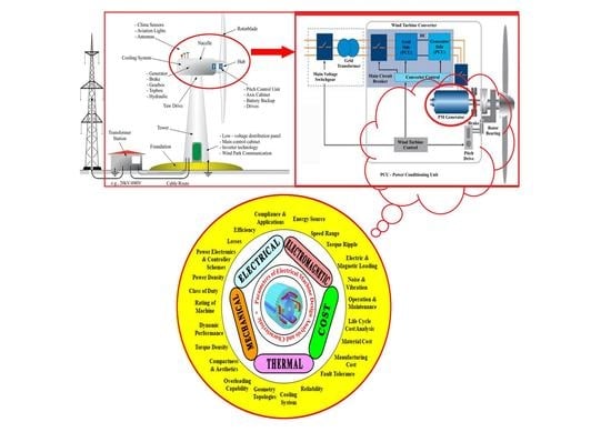


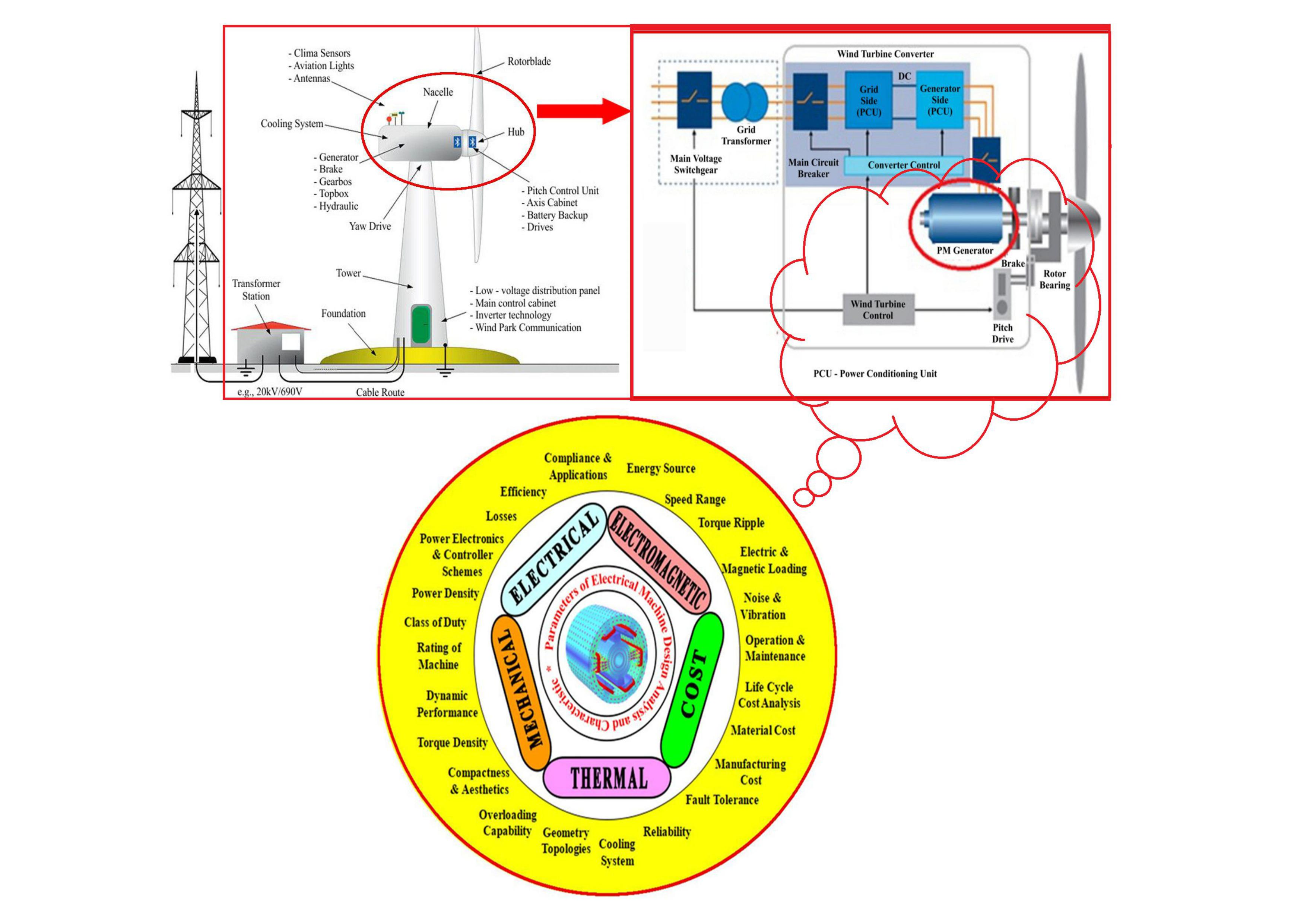
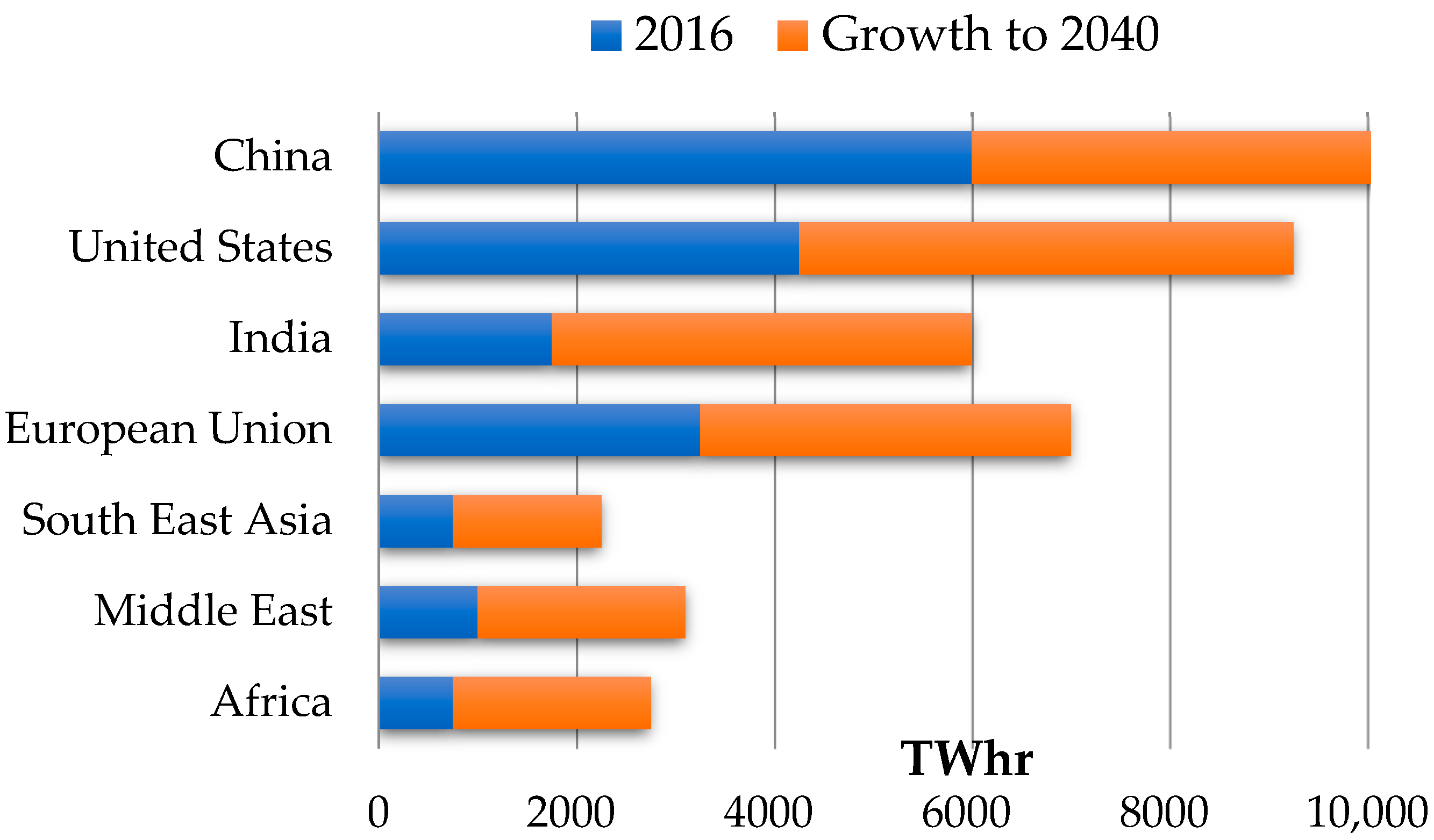
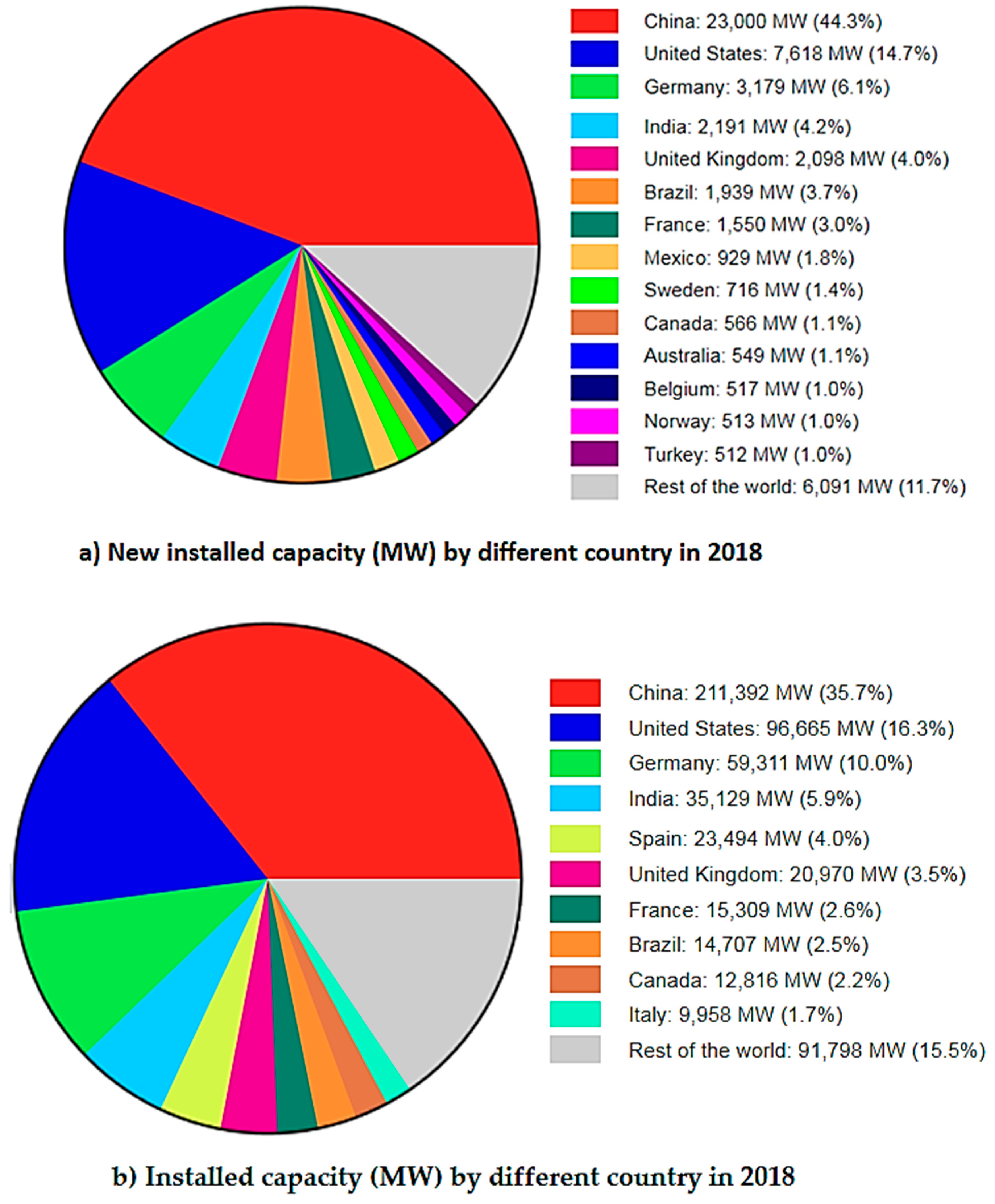
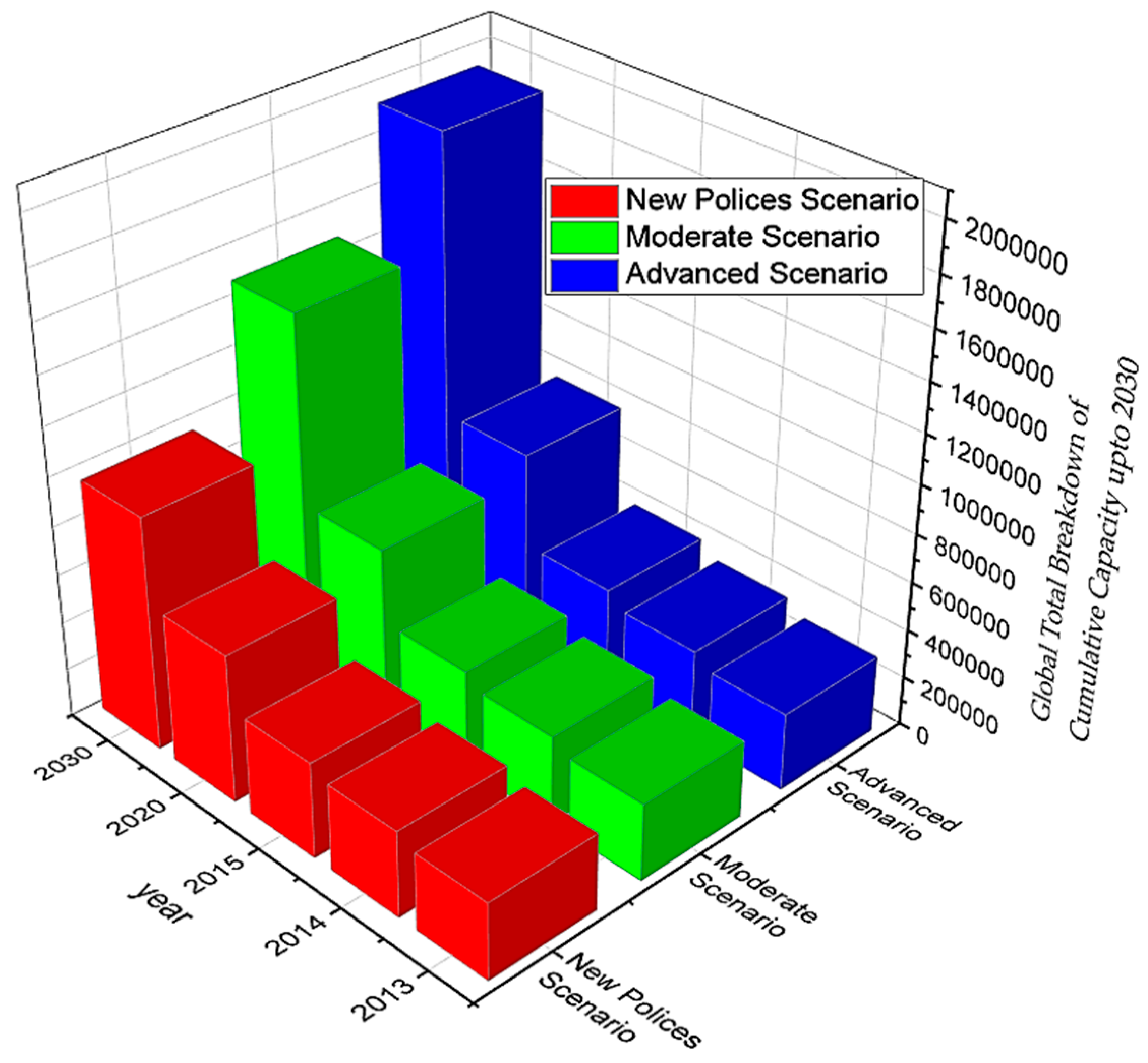
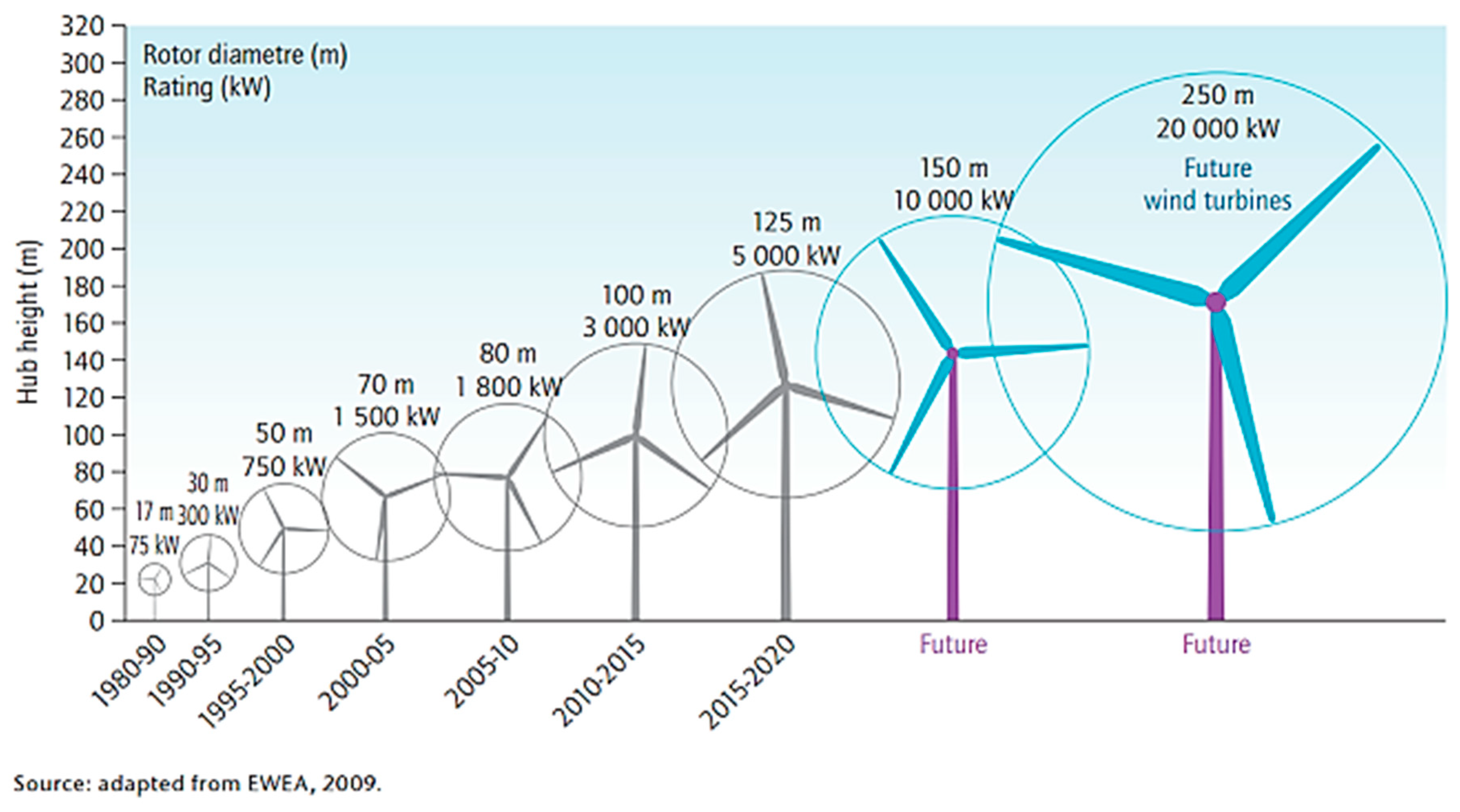
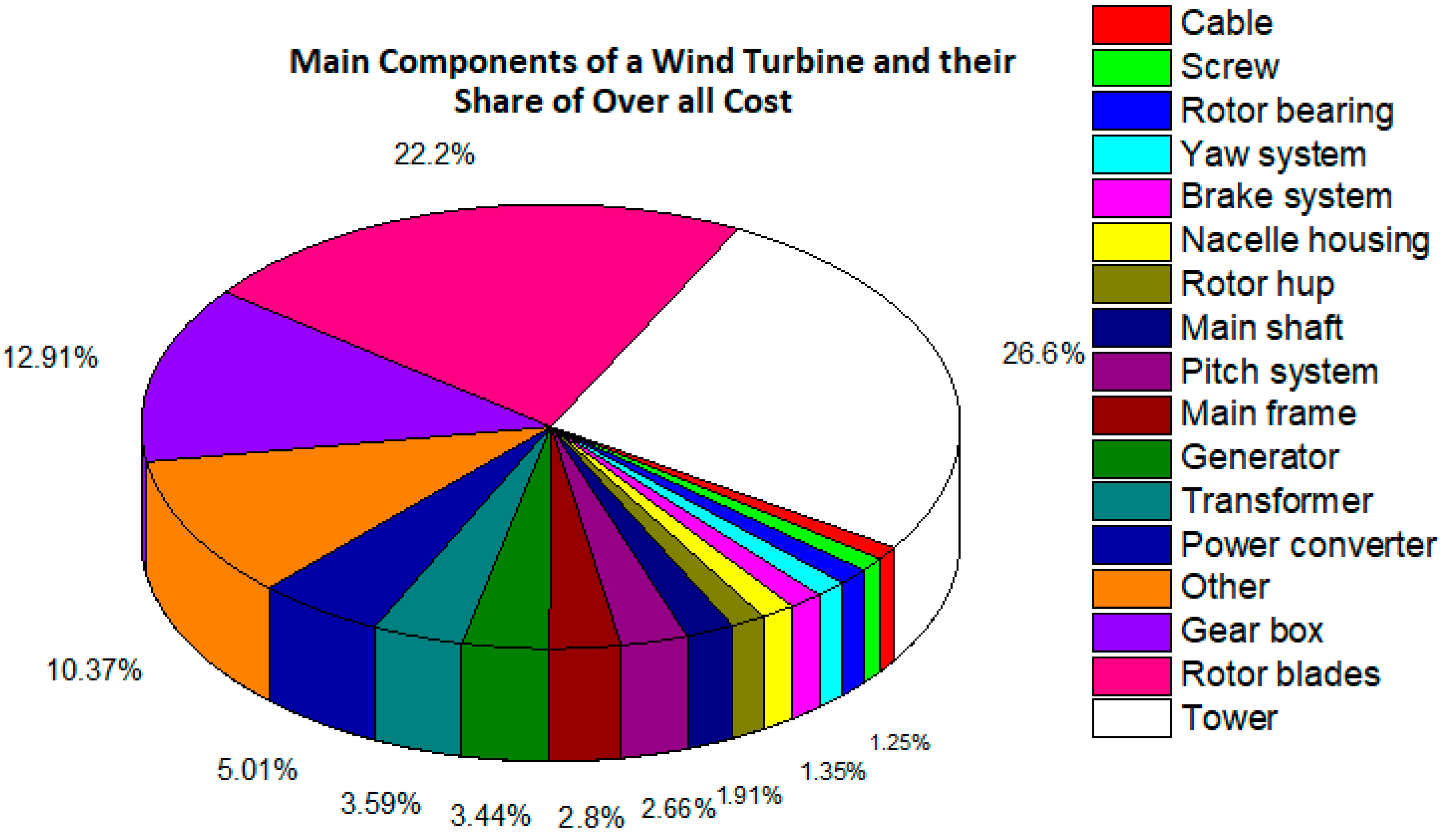
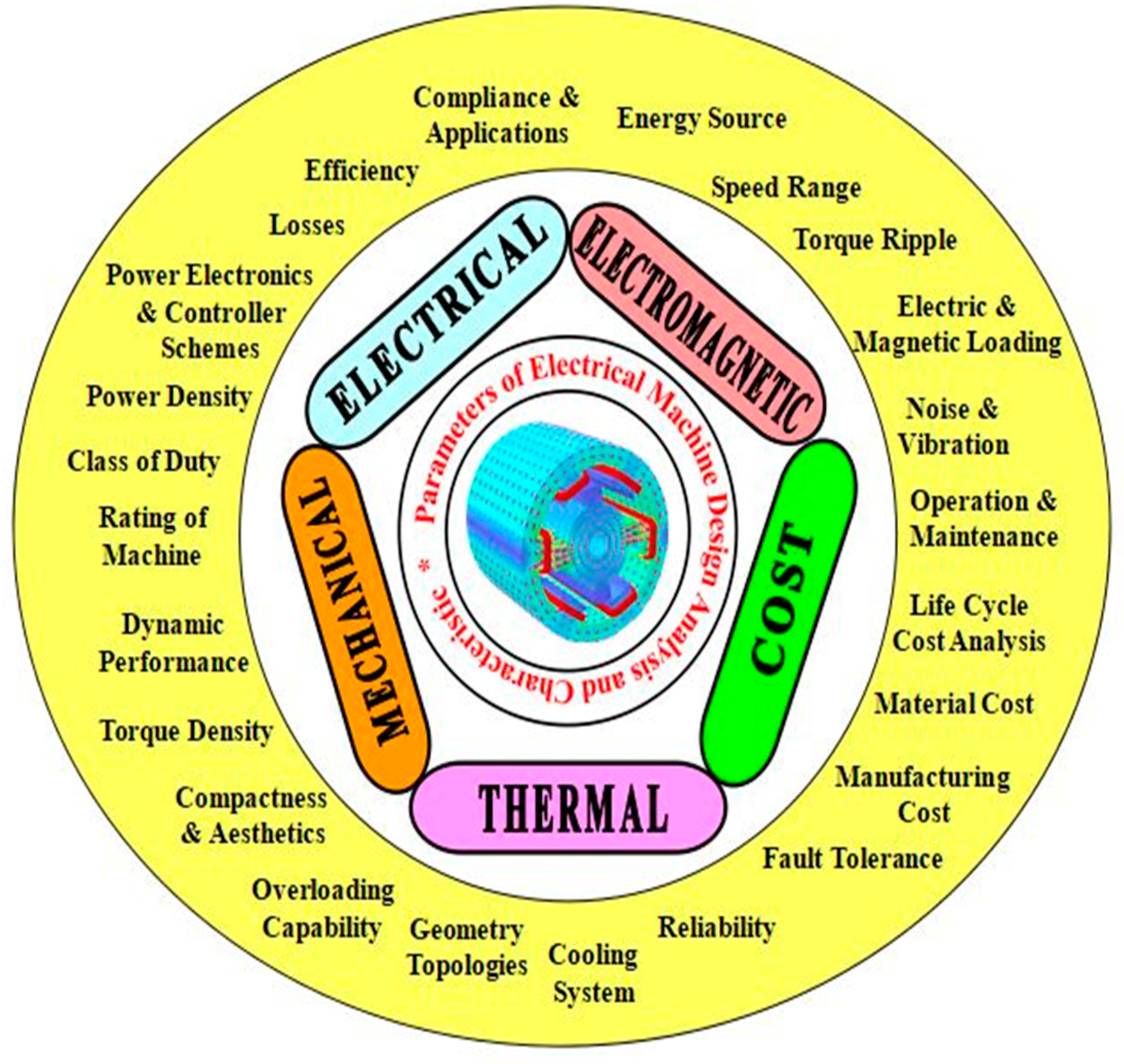
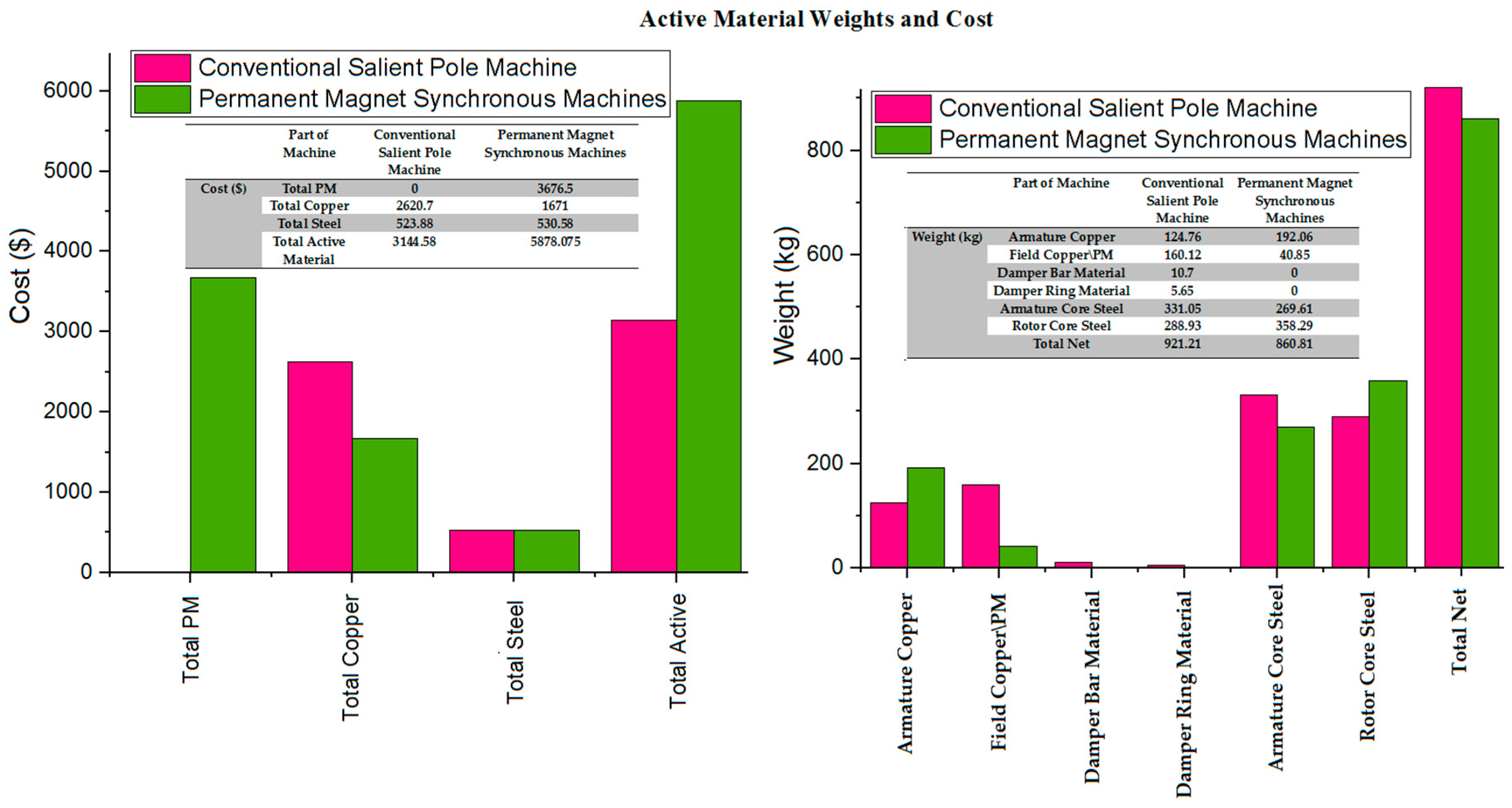
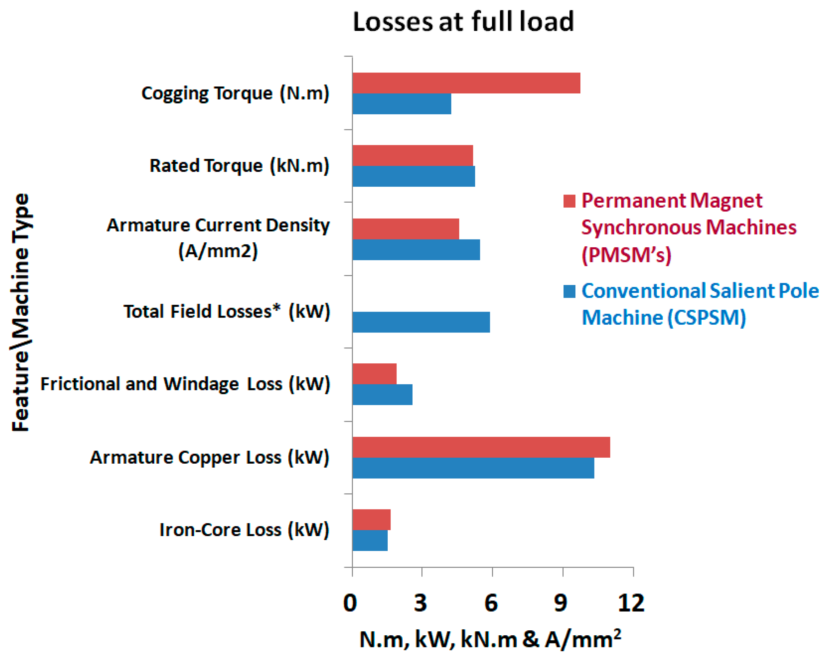
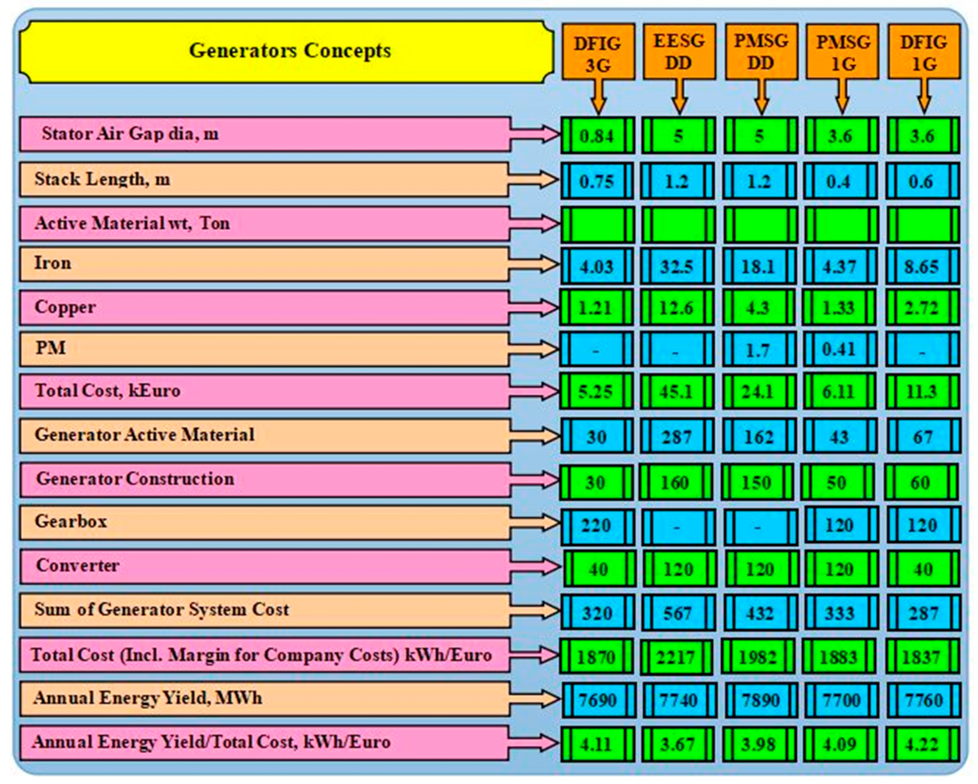
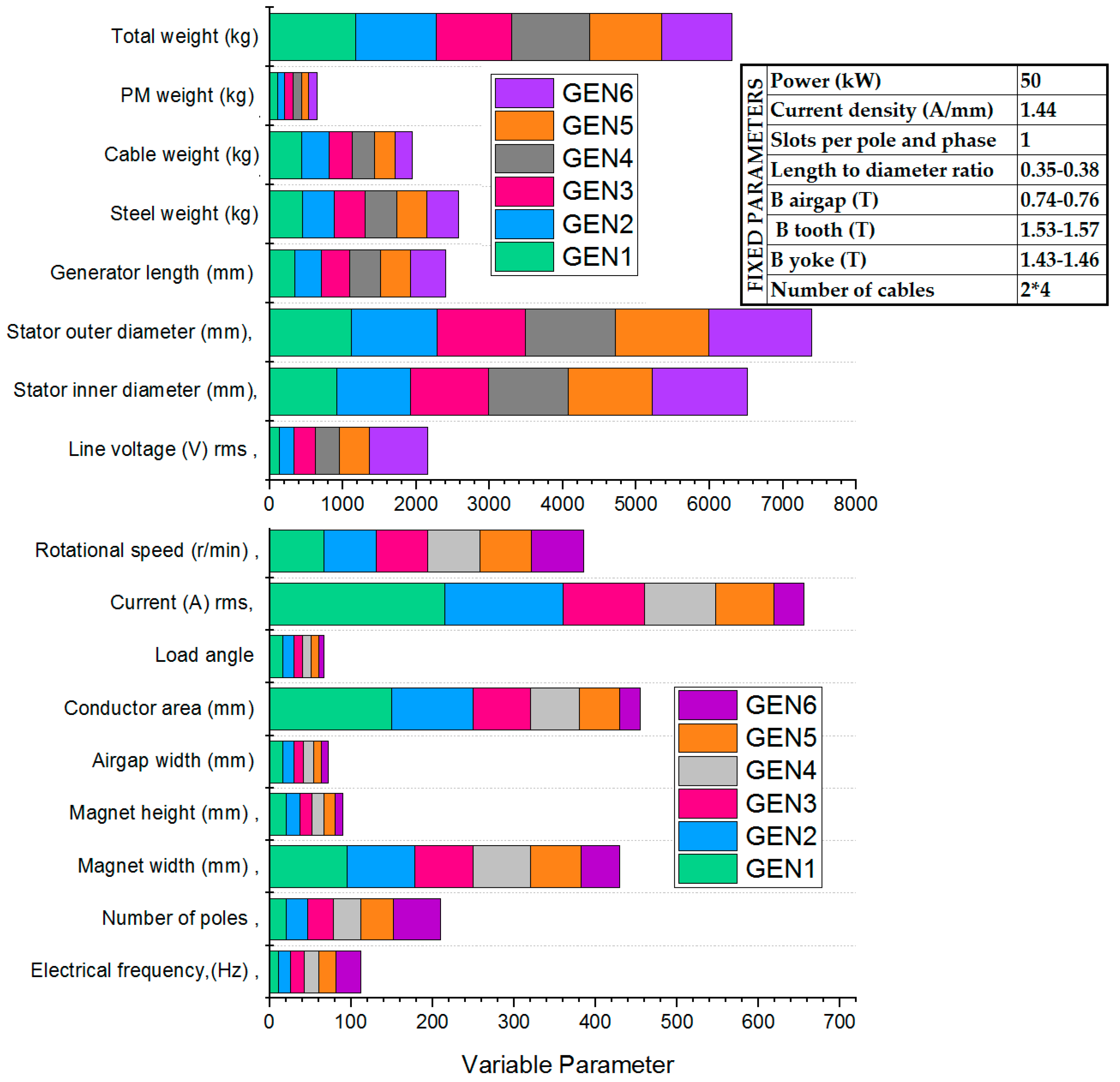
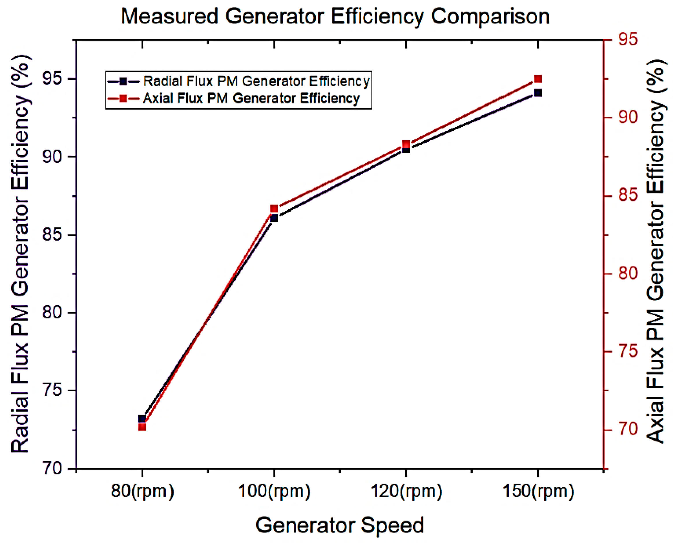
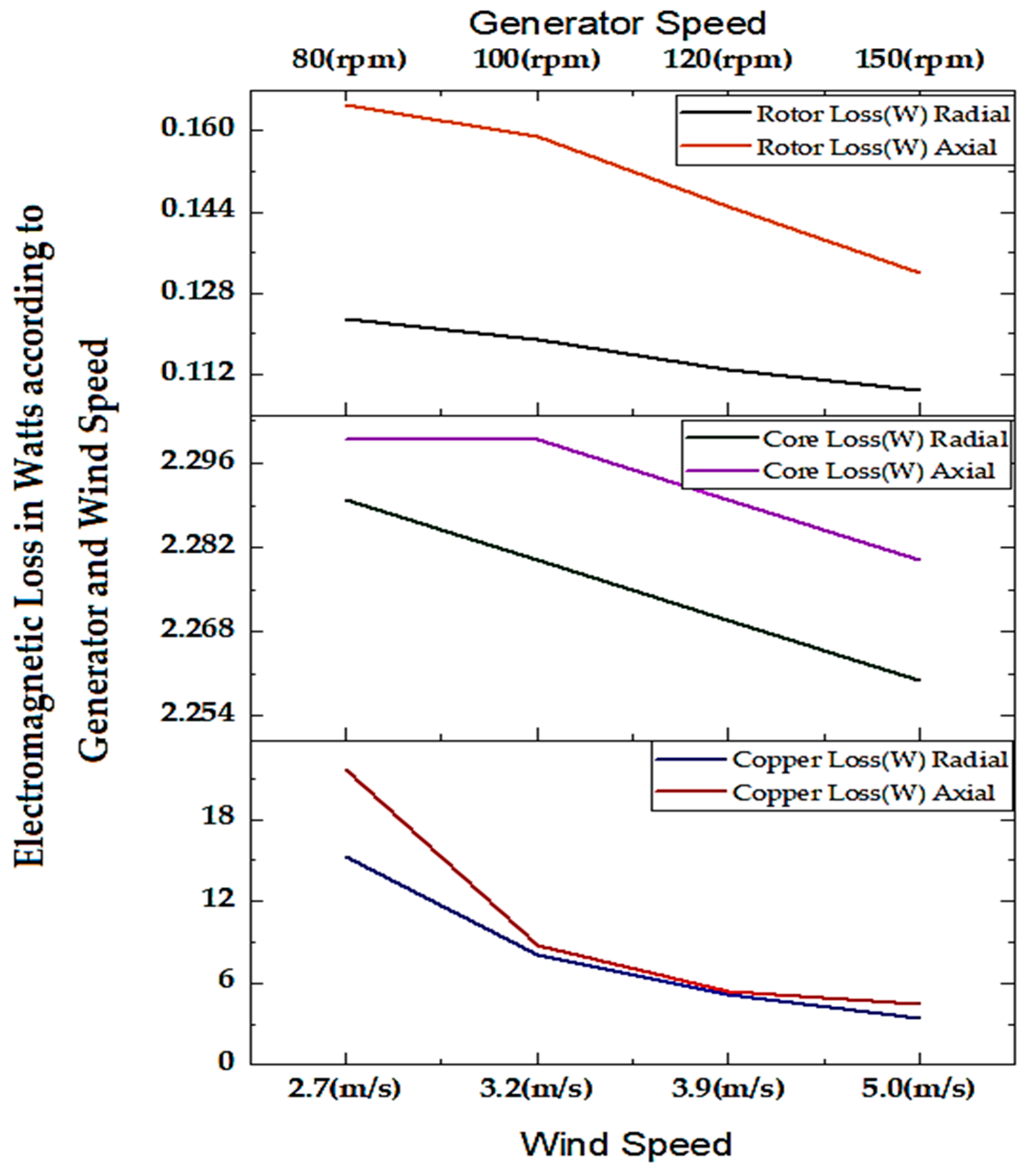
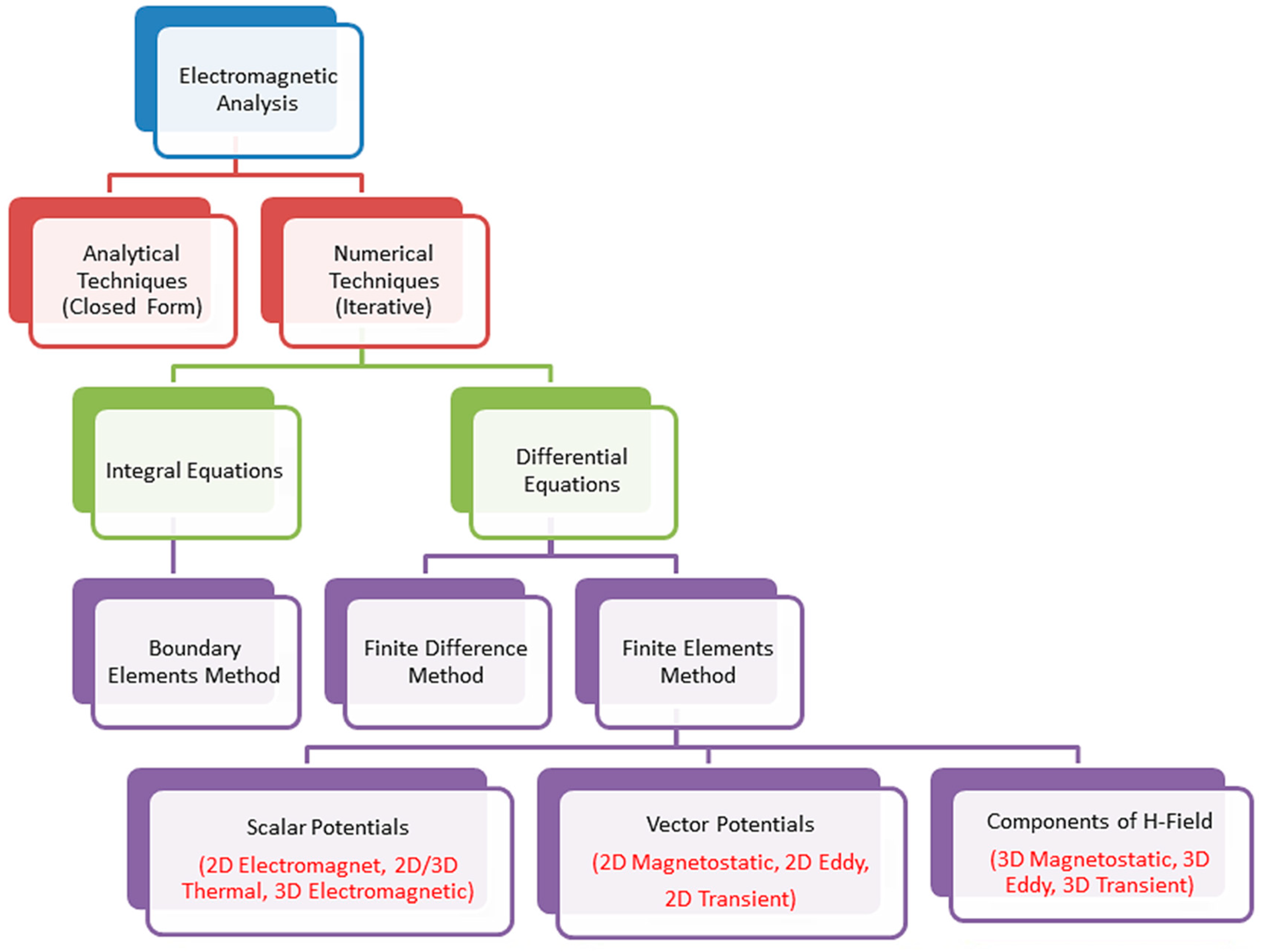
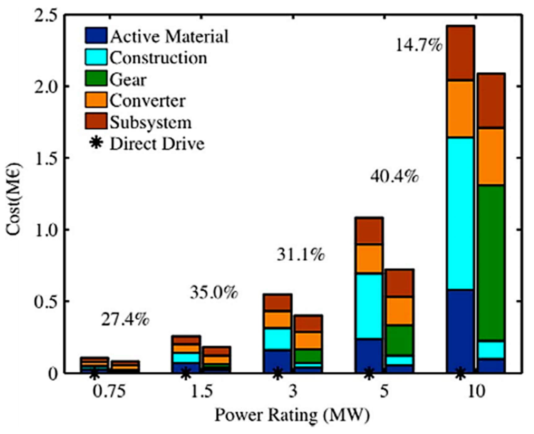
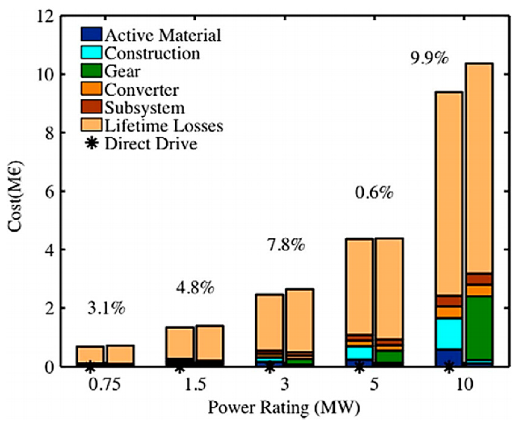
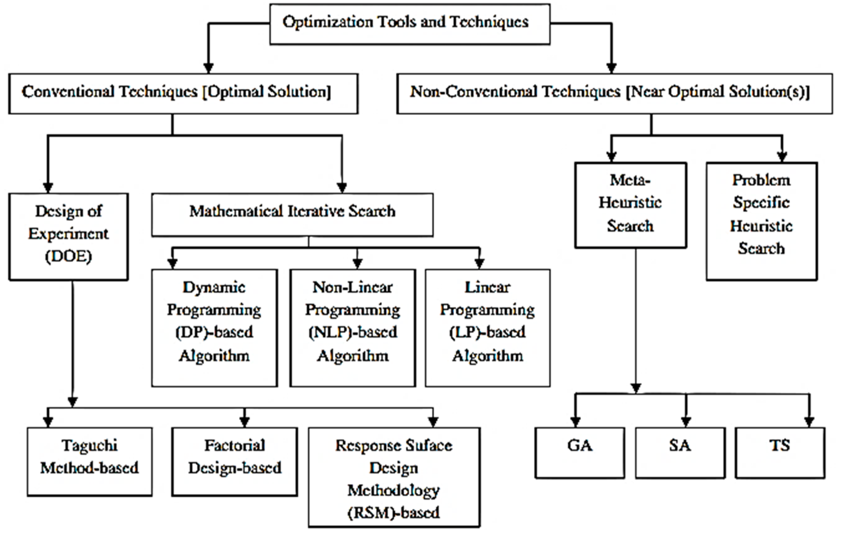
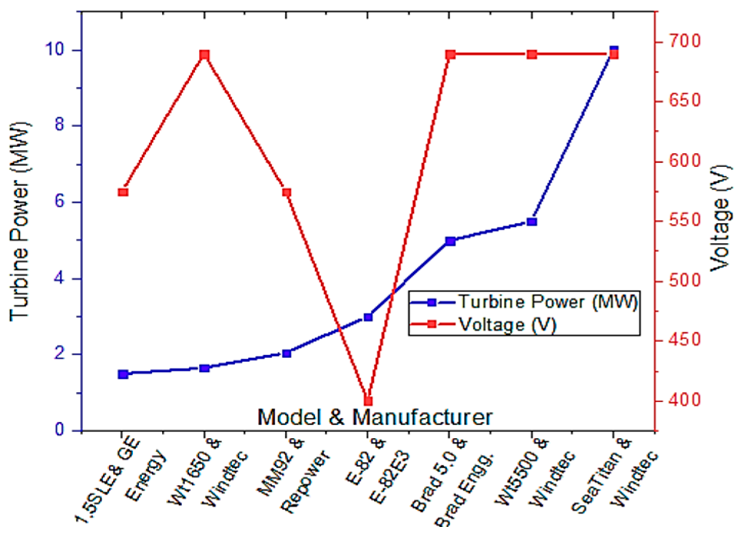
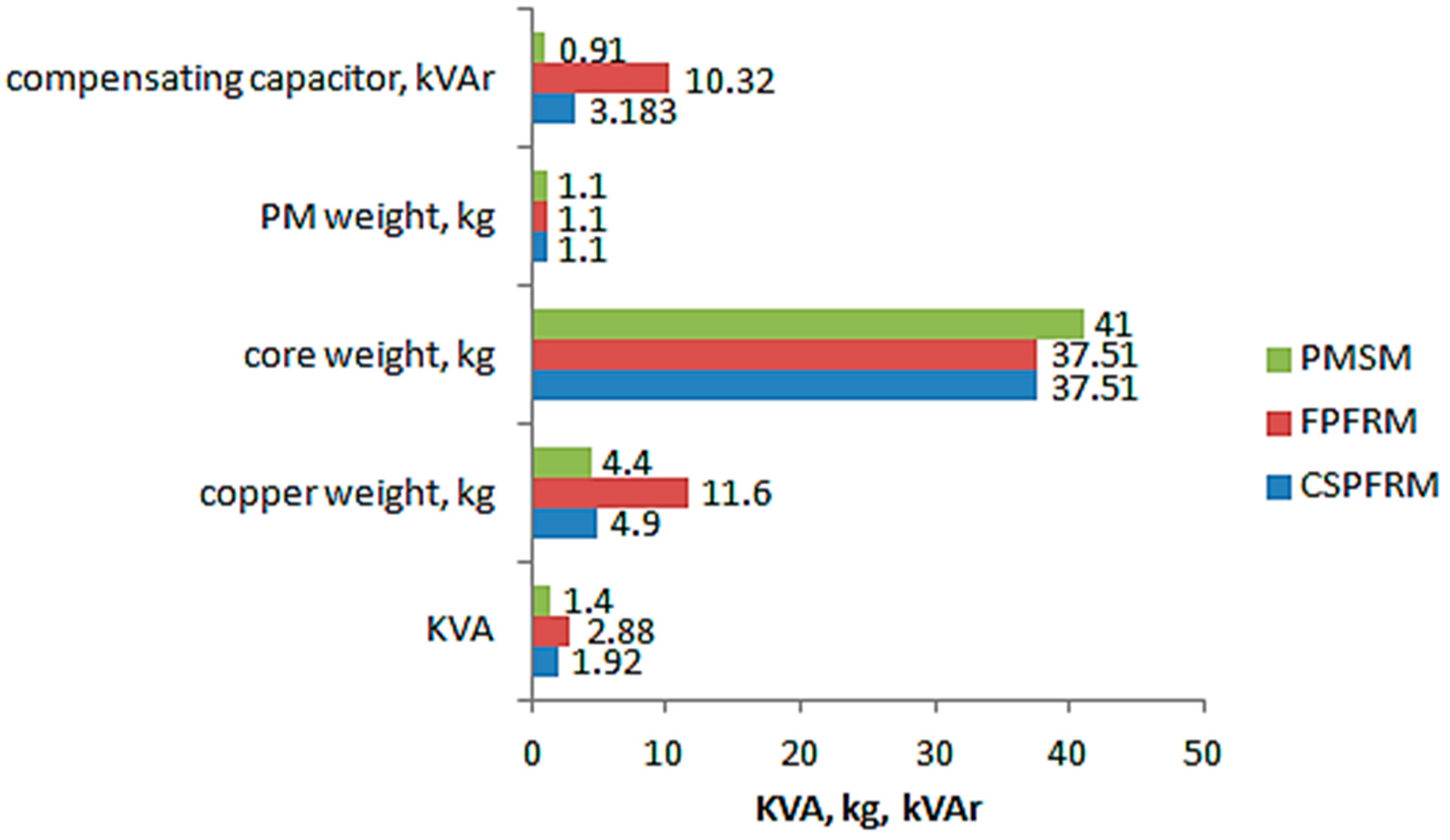
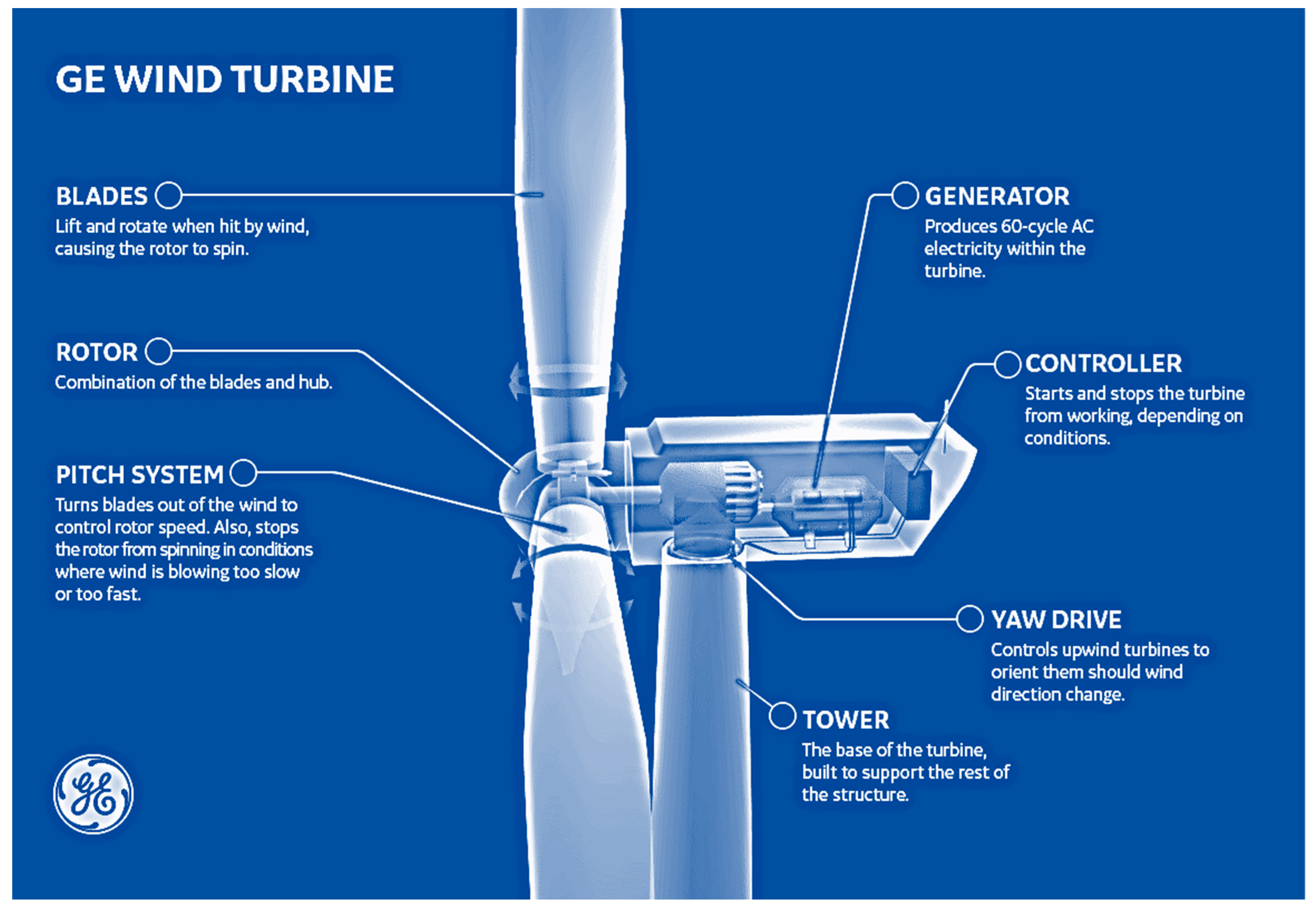