Article

A Three-Phase Transformerless T-Type- NPC-MLI for Grid Connected PV Systems with Common-Mode Leakage Current Mitigation

1
Department of Electrical and Electronics Engineering, Alagappa Chettiar college of Engineering and Technology, Karaikudi 630 003, Tamilnadu, India
2
Department of Electrical and Electronics Engineering, Thiagarajar College of Engineering, Madurai 625 015, Tamilnadu, India
3
Center for Bioenergy and Green Engineering, Department of Energy Technology, Aalborg University, 6700 Esbjerg, Denmark
4
Oregon Renewable Energy Center (OREC), Department of Electrical Engineering & Renewable Energy, Oregon Tech, Klamath Falls, OR 97601, USA
5
Department of Electrical and Electronics Engineering, SRM University, Chennai 603 203, Tamilnadu, India
*
Authors to whom correspondence should be addressed.
Energies 2019, 12(12), 2434; https://doi.org/10.3390/en12122434
Submission received: 4 June 2019 / Revised: 17 June 2019 / Accepted: 21 June 2019 / Published: 24 June 2019

Abstract

:
DC to AC inverters are the well-known and improved in various kinds photovoltaic (PV) and gird tied systems. However, these inverters are require interfacing transformers to be synchronized with the grid-connected system. Therefore, the system is bulky and not economy. The transformerless inverter (TLI) topologies and its grid interface techniques are increasingly engrossed for the benefit of high efficiency, reliability, and low cost. The main concern in the TL inverters is common mode voltage (CMV), which causes the switching-frequency leakage current, grid interface concerns and exaggerates the EMI problems. The single-phase inverter two-level topologies are well developed with additional switches and components for eliminating the CMV. Multilevel inverters (MLIs) based grid connected transformerless inverter topology is being researched to avail additional benefits from MLI, even through that are trust topologies presented in the literature. With the above aim, this paper has proposed three -phase three-level T type NP-MLI (TNP-MLI) topology with transformerless PV grid connected proficiency. The CM leakage current should handle over mitigating CMV through removing unwanted switching events in the inverter pulse width modulation (PWM). This paper is proposes PV connected T type NP-MLI interface with three-phase grid connected system with the help of improved space vector modulation (SVM) technique to mitigate the CM leakage current to overcome the above said requests on the PV tied TL grid connected system. This proposed the SVM technique to mitigate the CM leakage current by selecting only mediums, and zero vectors with suitable current control method in order to maintain the inverter current and grid interface requirements. The proposed PV tied TNP-MLI offering higher efficiency, lower breakdown voltage on the devices, smaller THD of output voltage, good reliability, and long life span. The paper also investigated the CM leakage currents envisage and behavior for the three-phase MLI through the inverter switching function, which is not discussed before. The proposed SVM on TL-TNP-MLI offers the reliable PV grid interface with very low switching-frequency leakage current (200mA) for all the PV and inverter operation conditions. The feasibility and effectiveness of the TLI and its control strategy is confirmed through the MATLAB/Simulink simulation model directly as compared with 2kW roof top PV plant connected TL-TNP-MLI experimentation, showing good accordance with theoretical investigation. The simulation and experimental results are demonstrated and presented in the good stability of steady state and dynamics performances. The proposed inverter reduces the cost of grid interface transformer, harmonics filter, and CMV suppressions choke.

1. Introduction

Photovoltaic (PV) based power generation is an unavoidable segment in the electrical power generation system (PGS) to meet the world power demand. The most recent renewables 2018 global status report indicates that 450GW of new PV plants have been set up worldwide in 2017, a 125% proliferation when compared to 2016 [1]. The reported global electricity generations from renewable energy sources alone in 2017 has been estimated around 26.5%, out of which 1.9% is from PV power generations.
The leading PV power producers were China, European Union, and the United States of America, with 131.1 GW, 108 GW, and 51 GW, respectively [2,3]. Countries like Japan, India, United Kingdom (UK), and Australia are the next pioneers in generating more power from PV planets.
Even though the price of PV panel has been mostly dropped, the complete cost of both the components investment and the generation of grid-tied PV system are quiet high. Hence, the PV tied grid-tied voltage source inverters (VSIs) are need to be prudently designed for accomplishing the low cost, high efficiency, and small size, in addition to low weight. The PV grid-tied VSIs are associated with the line-frequency transformers (LFTs) to afford galvanic-isolation in commercial PV inverter system structures. Nevertheless, LFTs are heavy and large, building the complete system bulky as well as inflexible to install. The use of LFTs for line-frequency isolation in grid-connected inverters, high-frequency isolation transformers are considered for their smaller size, lower cost, as well as total system weight. On the other hand, these high-frequency transformers connect inverter system have different power conversion stages, which affect the system and diminish the system overall efficiency and straightforwardness [4,5]. As a result, the PV grid-tied transformerless inverters (TLIs) are broadly used and installed in the low-power PV distributed generation systems (particularly 5kW and less). However inappropriately, TLIs are producing the common-mode leakage currents, which cause the leakage current flow due to the present PV panel parasitic capacitances [6]. This leakage current leads to serious safety concern and electro magnetics interference issues [7]. Hence, parasitic capacitances leakage current must be able to mitigate within a recommended choice [8]. Furthermore, the PV inverters tied grid-connected system should fulfill the grid interfacing standards and codes, leakage current detection, grid frequency protection, active and reactive control, and power quality standards [9,10,11,12,13]. Hence, the PV large manufacturers companies, such as Fronius international, Sunny boy, and SMA solar technology, are strict with PV standards and codes to satisfy the system safety and reliability requests. These companies are following German codes (VDE0126-1-1, IEC 60755 issued time, 2006 and VDE-AR-N-4105 issued time, 2011) for leakage current (less than 300mA) and grid frequency (47.5 < f < 51.5). Hence, over 300 mA leakage current, the PV inverter should be trigger to breakdown within 0.3 sec, as per the VDE 0126-1-1 code standard.
From the above-mentioned investigation, the important concerns in the PV tied transformerless inverters should be considered for efficiency, reliability, and cost. In industry practices, the commercial TLIs are designed with the total efficiency of more than 97% to 98 %. The total efficiency of the distributed PV tied TLI systems are manufactured by Steca’s Grid and Good We Technology’s, with 97.7% and 96.9%, respectively [14,15]. In view of PV inverters installation, 10%–20% overall installation cost is the initial system cost [16], hence the price drops for PV inverters installations certainly promote the PV product affordability. The U.S. energy department demonstrated that the TLI system for the residential systems (≤ 10 kW) had dropped from nine U.S. dollars to 4.8 U.S. dollars per Watt, since 2009 to 2014 [17].
Most of the installed PV plants are erected by single-phase type two-level voltage source inverter (VSI) topologies [2], which generate pulsating AC output power. Hence, the inverters require large DC-link capacitors; high collector–emitter voltage based switching devices and bulky filters ensure the grid standard codes. Henceforth for the last quarter decades, three-phase three-level NPC (3L-NPC) inverters are preferred for the alternate of two-level VSIs, which has been the hub of various research studies on PV applications [3,4,5,6,7]. Due to their small DC-link capacitors and the constant ac power on the output, NP-MLIs gave higher efficiency, lower breakdown voltage on the devices, smaller THD of output voltage, good reliability, and long life span [3,18,19,20,21,22,23,24]. Three-phase three-level NPC-MLIs are separated into two types (I and T) based on their leg shapes. After the arrival of T-type- NPC-MLI, I-type-NPC-MLI were evaded due to their long current commutation paths, higher stray inductance, and high conduction loss. The T-type 3L-NPC is being explored more to progress the better system efficiency [25,26,27,28,29,30,31,32]. The research on NPC-MLI has been extensively researched in PV and DC Distribution Network due its influencing of the stability, lower total harmonic distortion (THD), and lower electromagnetic noise [32,33,34]. These improvements mainly focused on DC-link balancing and common-mode voltage mitigations [35,36].
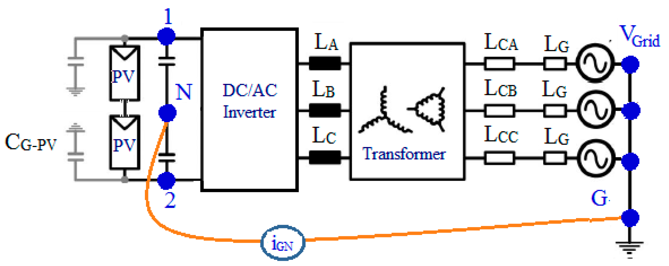
Most of the PV-tied grid connected inverter topologies are transformer based, which isolates the PV panels from the grid. The line-frequency transformer is avoided and high-frequency transformer is preferred due to the size and weight issues. However, the high-frequency transformer degrades the efficiency and makes the system more complex [37,38]. As a result, transformerless (TL) PV tied inverter–grid connection structure is greatly appreciated and studied by the power engineers due its less size, weight, and cost [39,40]. Although the TL inverters are able to gain system efficiencies of up to 97%, due to the absence of galvanic isolation and large stray capacitances, higher common mode voltage (CMV) is generated by VSI, which escorts the higher CM leakage current on the PV modules. Therefore, TL inverters suffer higher THD, ripple in grid current, degrading power quality, and warns of human safety, along with forming worsening EMI issues [41,42]. Figure 1 shows the leakage current bath for the Transformerless PV connected system.
The PV commissioning companies recommended limiting the leakage current, for example, in German standard 300mA, is used as the reference value. In order to keep this recommendation, most of the inverter manufacturers maintain expertise in inverter topologies, special controllers, and novel pulse width modulation (PWM) techniques. There are techniques for the TL system to reduce the leakage current through adding up devices in the inverter, such as diodes, switches, and passive elements [43,44,45,46,47]. However, changing the PWM switching pattern is more efficient than adding the devices and increasing the cost and reducing trust on continuous operation [37], which are mainly changing the pulses based on CMV development. When compared to other PWM methods, space vector modulation (SVM) is a pledge PWM to creating different PWM in a binary way. The methods use three medium vectors (3MV), keeps minimal CMV as the constant value, and it does not root less leakage current. Nevertheless, the maximum fundamental output voltage of the inverter is restricted VDC/2. A different method in [45] uses two MVs and one zero vector (ZV) and it does not cause the leakage current. However, similar to 3MV, its limited output voltage, and hence the better dc-link voltage, is compulsory to interface with the grid. Lee. J.S et.al has developed modulation techniques for reducing the leakage current while balancing the DC-link voltages. The method using the medium, zero, and large vectors reduces the CMV voltage that significantly roots the leakage current with better DC-link unitization [47].
Based on the aforementioned recognitions, a novel three-phase three-level TL T-type- NPC-MLI (3L-TL-TNPC-MLI) is proposed for the PV grid connected system with leakage current reduction. The novel TL-TNPC-MLI topology, together with the SVM strategy, have been proposed, aiming to improve system efficiency through the reduction of the commutation and conduction loss on the inverter, and leakage current reduction. The validity of the proposed inverter and its SVM control algorithm is verified for 1.5 kW PV grid connected system via simulation and experiment study. From the results, it is verified that the proposed inverter and PMW algorithm is well set for the perfect grid interface with reducing the leakage current.
The paper is outlined, as follows: nomenclature deals with the List of symbols and abbreviations. Section 2 accomplishes the analytical model and derivation of the leakage current on the three-phase transformerless MLI PV-grid connected system. Section 3 discusses the proposed PV tied three-phase three-level TL-TNP-MLI for th grid connected system. Section 4 and Section 5 accomplishes the MATLAB/Simulink simulations and hardware prototype experimentations. In conclusion, the advantages of the proposed system are presented in Section 6.

2. Leakage Current Analysis Transformerless PV Inverter System

In the PV tied grid connected systems, the isolation transformer is connected between the PV inverters and the grid, as shown in Figure 1. The parasitic capacitances (CG-PV) is connected in the 1 (dc+ terminal) and 2 (dcterminal) of the PV array. The mid-point of terminals 1 and 2 is called the neutral point (N). The voltage difference between terminals 1 and 2 is related to ground (G). The LA, LB, and LC are line the inductances of each phase, LCA, LCB, and LCC are the line inductances of each phase with respect to grid and, LG is the grid inductance. When the variations of the 1 and 2 terminals would source leakage currents from the PV panel to the ground. The leakage current value is depending on the amplitude and frequency of the voltage fluctuations and, in addition to the value of the parasitic capacitance (leakage capacitance) [26]. The leakage capacitance value depends on many factors, such as PV panel and frame structure, dust or salt covering the PV panel, and weather conditions, and so on.
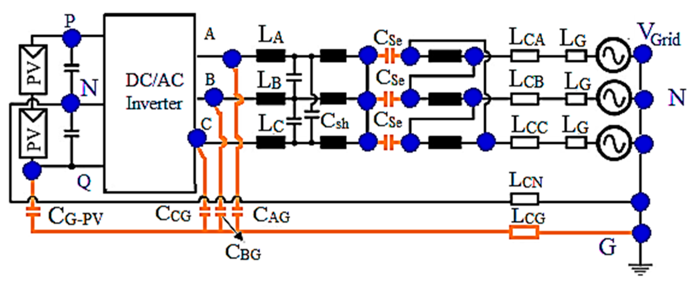
Due to the fact of CG-PV and inverter topology, common-mode voltage (CMV) is generated, which causes the common-mode current (CMC). The CMC is a danger, and it falloffs the PV lifetime [36]. In a general PV tied grid connected system with isolation transformer, the CMC can only find its path through the stray capacitances of the transformer. Generally, this is the reason why galvanic isolation (with a transformer) based PV systems are not affected due to the low frequency leakage current behavior, irrespective of the converters and their modulation techniques. As per German standard-DIN VDE0126-1-1, when the ground current goes beyond 300 mA (peak), the inverter needs to disconnect within 3 sec, and it furnishes the needs for restrictions concerning ground leakage and fault currents [18]. However, in TLI, due to the transformer absence, the converter and modulation methods can only do the CMC elimination. With this aim, the leakage current model is derived related with three-phase inverter switching. In order to illustrate the path for the common-mode current (CMC), the stray elements are added to the system, as in Figure 2.
Figure 3 shows the three-phase PV-grid connected inverter model with CG-PV and CMV source that individually calculate the CMV and differential mode voltage (DMV), and these can be related with the leakage current model.
Where the parameters are described, as follows; Csh is shunt capacitance; Cse is series capacitance; LCN is inductance between inverter neutral point and grid; LCG is inductance between PV terminals and grid; and, CAG,CBG, and CCG are the capacitances between each phase with respect to grid ground (see Figure 4).
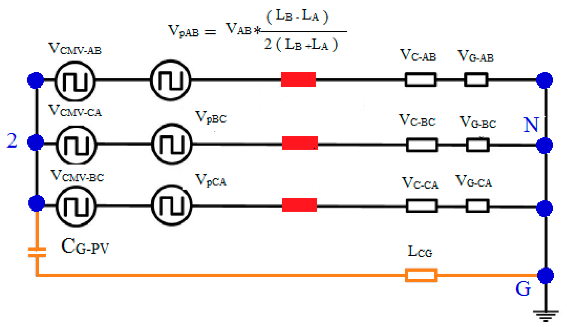
In a three-phase system, CMV and differential mode voltage (DMV) calculations between A to B or B to C or C to A phases are same. Thus, only A and phase B investigated in this paper. They calculated as [5],
CMV   between   A   and   B   phases ,   V CM AB = V AN + V BN 2
DMV   between   A   and   B   phases ,   V DM AB = V AN V BN
From (1) and (2), the out voltage expressed as
V AN = V DM AB 2 + V CM AB
V BN = V DM AB 2 + V CM AB
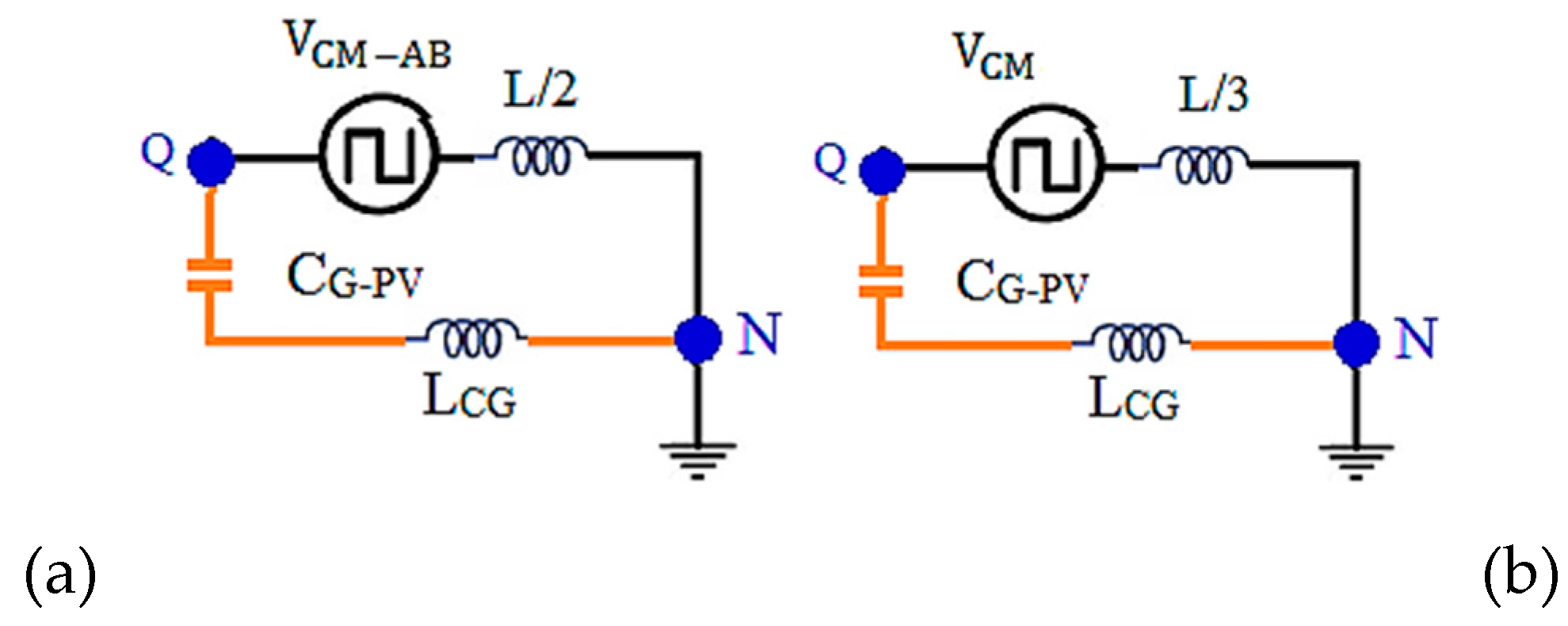
By observing the above equations, the CM model for A and B phases are shown in Figure 5 and Figure 6. Inverter stray capacitances are significantly identical, since the output inductances are identical for all three phases; the model can be simplified, as presented in Figure 7a. The final CM equivalent circuit model for the three-phase system is based on the designed two-phase circuit CM model, as shown in Figure 7b.
The CMV for all three phases expressed as [20],
V CM = V AN + V BN + V CN 3
The output voltages of the three-level VSI are determined, based on the inverter’s legs connection with one point among P, N, and Q, as in Figure 3. If the grid ground (G) is the standard, these three connection points’ output voltages are VDC + VN, VDC/2 + VN, and VN, respectively.
The grid currents is expressed as [5],
V AN + V N E a z L + V BN + V N E b z L + V CN + V N E c z L = 0
ZL is the impedance of the L-filter
Sum of grid currents is zero,
E a   + E b   + E c   = 0
V N = V AN + V BN + V CN 3
From (5) and (8), the V CM is related to the output voltages of inverter, which means that V CM can be influenced by the inverter switching state.
Consider that Sa, Sb, and Sc are the switching states of the inverter legs. Hence, the switching function is defined as,
S A , B , C ( V AN ,   V BN , V CN ) 1 ,   1     2   , 0 =   V DC   V DC / 2 0   V DC   V DC / 2 0   V DC   V DC / 2 0
From (6) and (9)
  V N   or   V CM = V DC (   S a ) + V DC (   S b ) + V DC (   S c ) 3
From (10), the possibilities of the CMV in the inverter switching are −VDC, –5VDC/6, –2VDC/3, –VDC/2, –VDC/3, –VDC/6, and 0. These ac-components of VN cause the leakage current through the line, including CPV.
Further, the leakage current is calculated, as [5],
| I CM | = | V CM | | Z PV |
Due the square wave CMV nature, the total CM leakage current is the addition of odd multiples of switching frequency current components. Hence, the total leakage current ( I TCM ) is obtained, as [5],
I TCM = n = 1 , 3 , 5 , 7 , . . | I CM ( nf ) |
From (12), if the switching frequency increases, there is an increase in I TCM . However, it is not proportional to the switching frequency due to the damping resistor, the leakage resistor on the PV, RPV. From the above discussion, I TCM is influenced by leakage capacitor CPV, and the switching action of the inverter. Hence, inverter switching based leakage current elimination is the best method, since CPV is decisive by the environmental factors.

3. Proposed PV Tied Three-Phase Three-Level TL-TNPC-MLI for Grid Connected System with Leakage Current Reduction

This section discussed the proposed PV tied grid connected TL-TNPC-MLI, including CM leakage current elimination by using the full CM elimination switching technique with grid interfacing.

3.1. TL-TNPC-MLI Operation for Zero CMV.

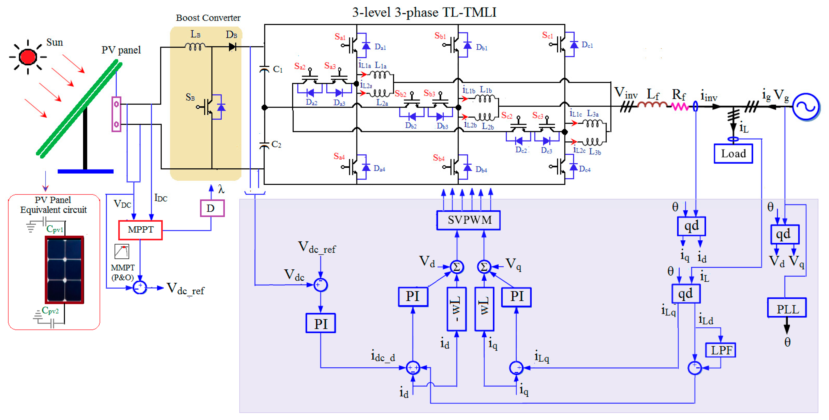
Figure 8 shows the three-phase 3L-TL-TMLI power circuit, which has 12-IGBTs (Sa1-Sc4) and 12-anti-parallel free-wheeling diodes (FWD; Da1-Dc4) three-phase 3L-TL-TMLI power circuit. It involves three-phase leg with four IGBTs (Sa1-Sa4) and four FWD (Da1-Da4) in a leg. Here, the top and bottom switches IGBTs/diodes (Sa1/Da1and Sa4/Da4) that were employed with 1200V and middle switches (Sa2 / Da2 and Sa3 / Da3) operated by two 600V. Hence, due to small blocking voltage, middle switches consume very less switching and conduction losses, even though there are two devices that were connected in series [40]. The inverter includes two dc-link identical capacitors (C1= C2= VDC/2) and six equal value split inductors (La1 = La2 = Lb1 = Lb2 = Lc1 = Lc2 = L). In view of T-MLI with TL concept, the ground connection is the essential one for any TL inverter topologies, while the centre of PV cluster does not ground, the proposed TL-TMLI output terminals can be abundantly associated to the grid; else, mid-point (N) of both the dc-link capacitors (VC1 and VC2) must be connected to the PV cluster mid-point and grid neutral (G). Table 1 illustrates the switching operation of TL T-MLI, the modes of operation is situated based on the dc-link mid-point (N) connection to DC+, N and DC-. There are 27 possible switching states of operation on 3L-TL-TMLI for the full cyclic operation of one grid cycle. Here, the modes are created based on the switching ON and OFF position on each inverter leg. These modes are categorized in four groups (G-1 to G-4). The possible switching state and its switching groups are tabulated in Table 2.
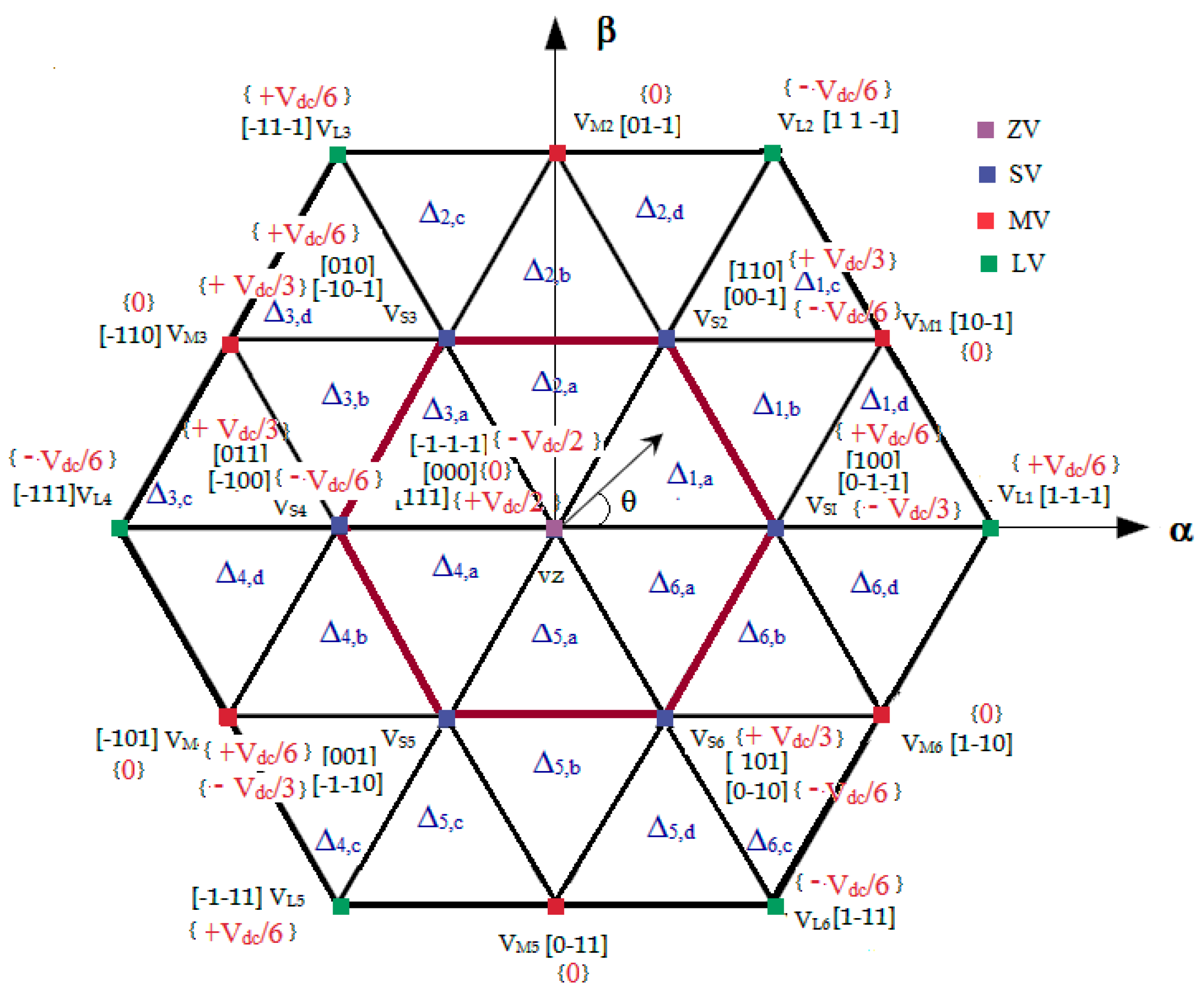
By applying the switching states in equation (10), each switching state has different possibilities of the CMV in the inverter switching are Vdc/6, Vdc/3, Vdc/2, 0, −Vdc/6, −Vdc/3, and −Vdc/2 as shown in Table 3. For example, for the -1-1-1 switching state, the obtained CMV is V com [ 1 1 1 ] = 1 3 · ( 3 ) · V dc 2 = V dc 2 . Similarly, the MV 10-1 switching state CMV is V com [ 1   0 1 ] = 1 3 · ( 0 ) = 0. Table 1 illustrates the CMV for the different switching state inverter. For all 27 switching states, the CMVs are summarized as +Vdc/2, 0, +Vdc/3, +Vdc/6. Figure 8 shows the space vector diagram (SVD) for three-level TMLI with their switching and ITS corresponding CMV. The SVD consists of six sectors, 27 switching states, and 24 sub-triangles Here, every switching states has its own CMV, which is tabulated as seven groups and the same represented in three-level SVD, as shown in Figure 8. Here, expect group-D (six MVs and one ZV) all other group switching states are producing CMV and these CMV components cause the leakage current through the line, including CPV.
While operating SVM by selecting D –group-switching sequence, the CMV is fully eliminated, and, as a result, leakage current is fully eliminated. Figure 9 shows the refined SVD with using only D-group switching. When considering the case of V* moving in sector-1 in order to zero CMV, the suggested switching structure uses zero CMV vectors, as VZ [000], VM1 [10-1], and VM2 [01-1]. The uses of MVs with ZV facilitated by fixing/switching at the middle of the sector are 30, 90, 150, 210, 270, 330, (-30). Hence, the proposed scheme trundles on the principle of reference phase angle discrete hoping. Thus, sector-1 is reordered between -30 to 30 (−300 < θ >300). Similarly, sector-2 is 30 to 90 (300<θ>900), and so on. This angle determination procedure has expanded for all six sectors in the SVD and each sector consists of the three zero CMV switching vectors (two MVs and one ZV switching state) as shown in Figure 10. Of course, due the absence of LVs, the full CMV elimination limited ma is to 0.7. Therefore, the inverter output voltages reach up to 70% from the full linear ma range. The dc-link voltage of the inverter must be increased in order to increase the voltage performance.

3.2. Proposed Close Loop Grid Connected TL-TNPC-MLI

Figure 11 shows the proposed control system block. As presented in closed loop system, the PV panels are and controlled by P&O—maximum power point tracking (MPPT) method and the control output drive the boost converter to meet the desired dc-link voltage for the inverter. To connect the inverter power with utility grid, the phase lock loop (PLL) that is used to measure the phase locked angle of the grid voltage (θ) and its nominal frequency (wr) from the Vg. The three-phase inverter (iinv) and load current (iL) are converted from abc to dq to match the PV output Vdc.
By using (13) and (14), according to [20], reference Vα and Vβ are generated, which control the SVM to achieve the inverter grid interface.
V α = wLi d + V d + i dc _ d
V β = wLi q + V q + i L _ q
Finally, the predetermined component (Vα and Vβ) is given to the SVM block, which gives the voltage control reference (V*) with desired modulation index (ma) to match the grid voltage.
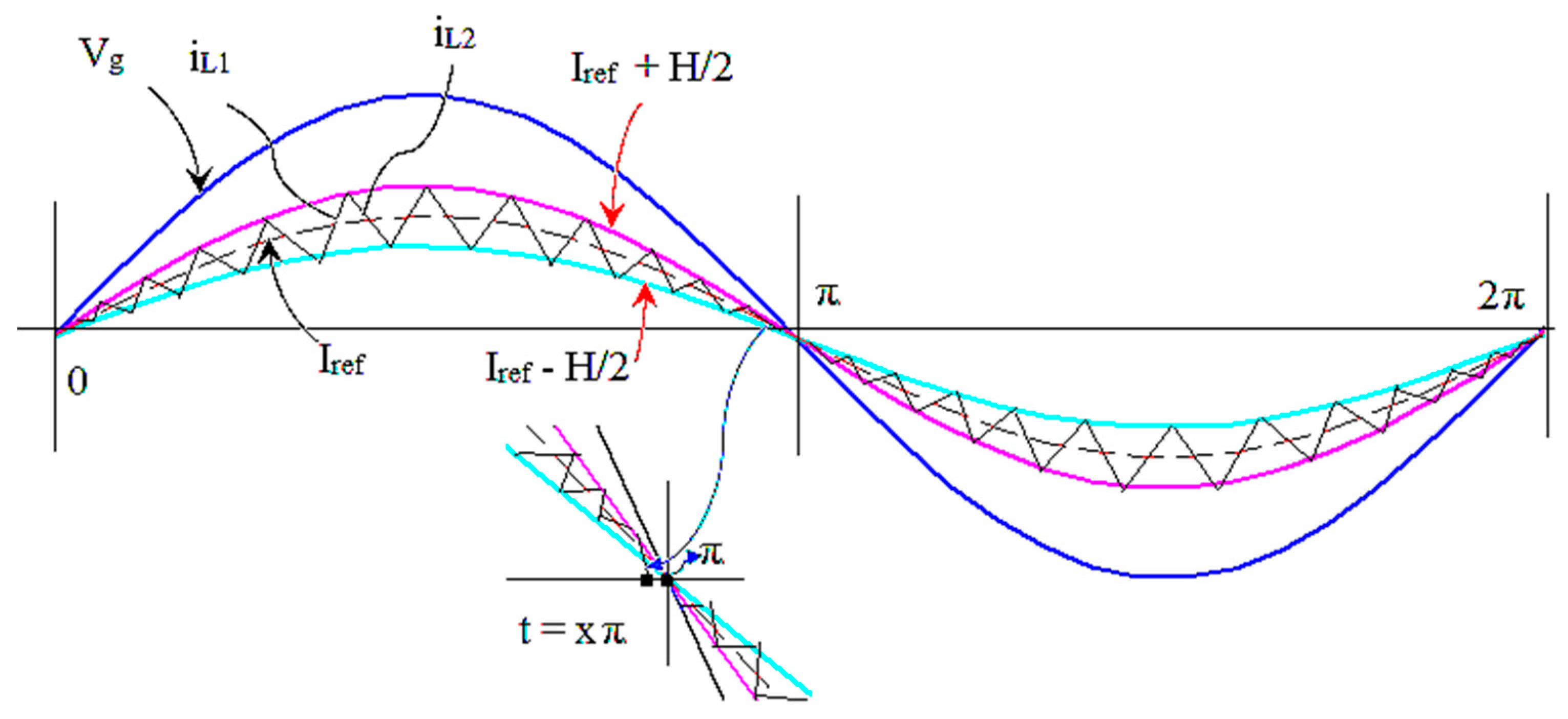
The hysteresis current control (HCC) is used for controlling the inductor current based on the grid current reference. The proposed HCC is giving suitable switching sequence to SVM for controlling inverter. In any HCC, it is necessary to retain the actual load current near the reference load current within the hysteresis boundaries. The main mathematical challenge in current controllers is to generate the reference current components. Figure 12a illustrates the building block of HCC of an inverter. Here, the reference current ( iref ) is related with the actual current (iact) to produce the error current, ε i = (iLref - iLact), which will produce the error gain (control input u(t)) between the two hysteresis bands BU and UL (upper and lower hysteresis bands) [24]. This control signal generates the control input u (t) to drive the inverter.
The Sinusoidal PWM (SPWM) based conventional HCC (CHCC) involves three individual references. Therefore, due to the non-interference between the commutation phases, the CHCC deviates from the variable switching frequency over the fundamental frequency cycle, which results in an irregular inverter operation. This happens, because each phase current not only depends on the corresponding phase voltage, but is also affected by the other voltages [23]. However, SVM-based CCs control the current using a single reference vector. Here, the tip of the reference current vector moves around the hexagonal-coordinate system in SVD [20]. Some of the research on HCC for MLI has been attempted through SVM [24,35]. However, these controllers have difficulties in attempting to make a direct current control and they use more numbers of hysteresis bands in order to achieve the results.
Unlike the reported CHCC and SVCC, the proposed HSVCC not only maintains the current, but it also takes care of dc-link capacitor balancing for the inverter, which assures the capacitor balancing within the recommended significance and produces the effective output voltage with current control to the grid. These switching options enables the CC with capacitors balancing throughout the operating condition (change in PV, Inverter, and grid parameters).
Here, when the reference current (iLref) and actual current (iLact) lie in SVD, and it is expressed as [24],
i L r e f =   i L r e f _ α   + j i L r e f _ β
i L a c t   =   i L a c t _ α +   j i L a c t _ β
Subsequently, the error vector, ε i is calculated from (2) and (3),
ε i = i L r e f     j i L a c t
Now, the ε i expressed in the αβ-vector components frame is
ε i = Δ i α   +   j Δ i β
From Equation (5), the position of the ε i in SVD is calculated and the switching vectors are then selected to keep the i Lact close to the i Lref .
It is assumed that the inverter has unity power factor (PF), i.e., the inverter current iL is in phase with the grid voltage Vg. This assumption is true for PV grid-connected inverter (unity PF between the in-grid current and the grid voltage). The high frequency inverter switching pulse (fs) must be stopped at the time xπ in order to confirm the zero-inverter current beforehand the zero crossing of the Vg, hence the inverter current is forced to zero by the grid voltage, as shown in Figure 13.
The time xπ to turn OFF the high-frequency inverter switching signals is calculated from the inverter switching action for an interval between x to x.
x π π [ V g . sin ( wt ) + V D ( ON ) + V S ( ON ) ] L I ref . sin ( x π ) + H 2
Here, VD (ON) and VS (ON) are the ON-state voltages of clamping diodes and the power switches, respectively; ‘H’ is the bandwidth of current hysteresis, i.e., the ripple of inductor current, and x is the percent of high-frequency driving signal continuance. HCC is a nonlinear controller, which has high performance, high stability, and fast dynamic response. Nevertheless the output current is widely distributed in the energy of spread-spectrum due to the unfixed switching frequency. Therefore, the filter design is highly difficult. There are many studies on hysteresis band calculation [37]; among them, the real-time regulation method that was based on the switching frequency is the effective method for the calculation of the H value. Fixed frequency HCC can be obtained by calculating the hysteresis band H while using the transient value of the Vg and output voltage of PV array. Based on that, the hysteresis band ‘H’ is calculated as,
H = V g ( V PV 2 . V g ) V PV . L . f s
Here, the variant parameters are VPV, Vg, fS, and fixed one is filter inductor (L)

4. Simulation Validation

The performance of the proposed PV connected three-phase three-level TL-T-MLI simulation models are performed while using MATLAB/Simulink 14.b. Here, the 2 kW PV array module is configured (series model) to feed the power to inverter with each module rated at 152.5W. The T-MLI maintains the dc-link voltage that is close to 456V by the help of two (C1 and C2) 470μF capacitors. The inverter is connected to 230V/50 Hz utility grid via 4 mH quality split inductors, Lx1 and Lx2 (where. x = a,b,c). The inverter switching frequency (fsw) is maintained throughout the operation of the inverter as 5 kHz. Simulation studies are carried out in two main directions: verifying the validity of the current controller for controlling inductors current and validating the grid connection of PV tied TL inverter with zero circulating current.
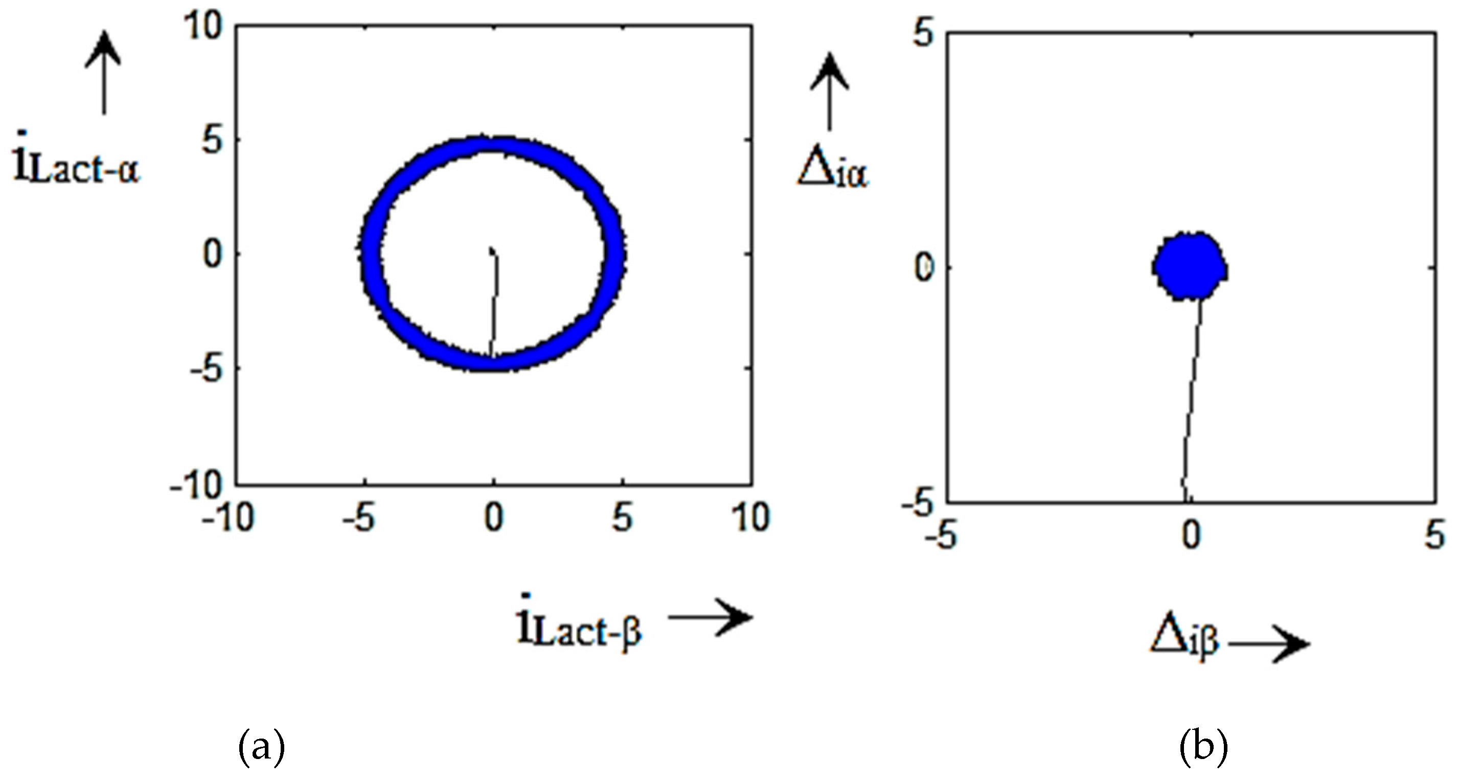
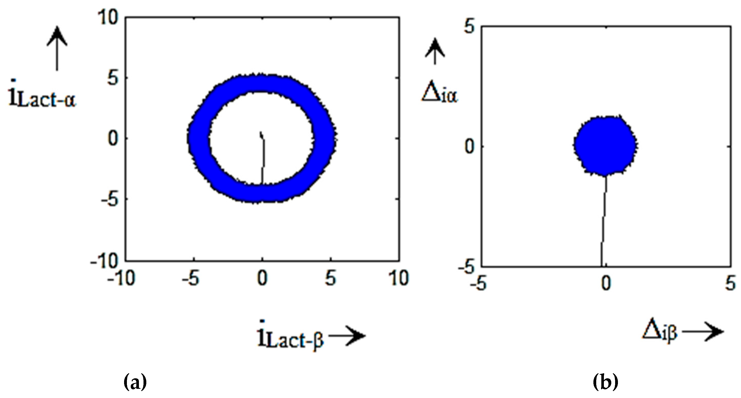
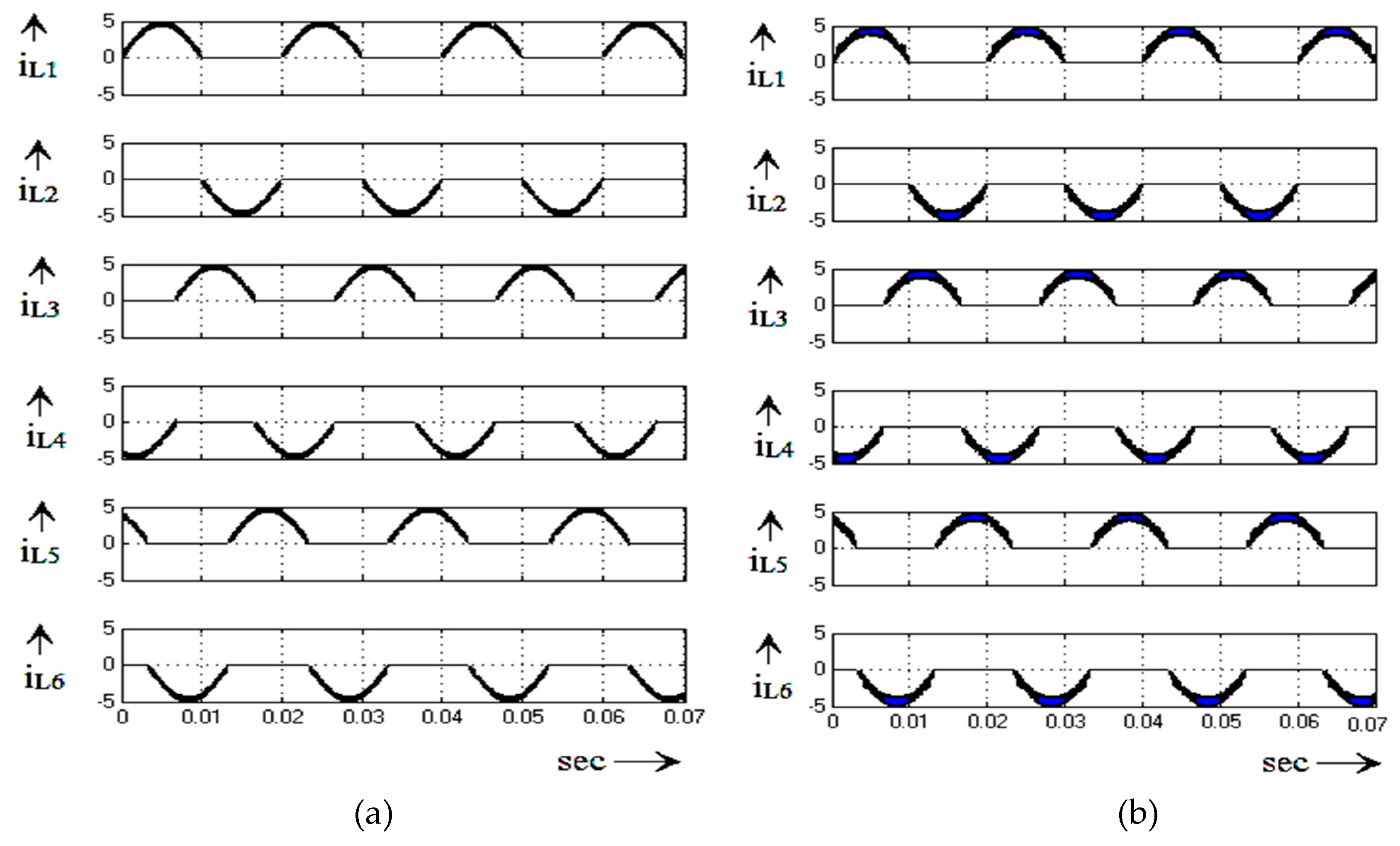
Initially, the PV is set to obtain 456V DC-link voltage for T-MLI. The simple boost converter with the P&O Maximum power point tracking (MMPT) method is used to maintain the MLI DC-link as constant. Figure 14 shows the model of the PV array with the MPPT algorithm results, which is taken at various irradiations and constant cell temperature in increasing and decreasing irradiation with the oscillation of MPP voltage. From the results, it could be seen that the MPPT algorithm was able to follow the MPP of PV array within 1.5 times grid period. The inverter operation tested for variable and fixed band hysteresis. In Figure 15 and Figure 16, the current error (∆ei) trajectory and controlled current trajectory in α-β plane for variable and fixed band hysteresis are shown. These results indicate the HCC characteristic operation and its error minimization are well worked for both bands. When the TL T-MLI operates in the HCC with a fixed band and variable band, the waveforms of iLref and iLact are shown in Figure 17. From the results, it can be viewed that iLact visibly tracks iLref and minimizes the error by using the proposed HCC for both the fixed band and variable hysteresis band, which ensure the perfect inverter current synchronous with grid voltage. Figure 18a,b shows the inverter leg inductor currents (iL1 to iL6) for variable and fixed band hysteresis. It shows that all of the inductors are properly and identically charged. Hence, three-phase inverters current are equal to each other.
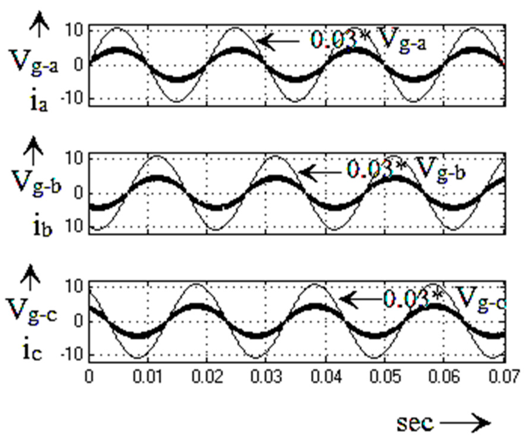
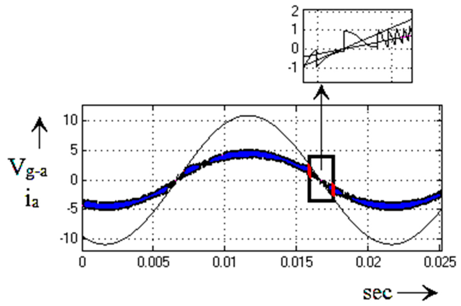
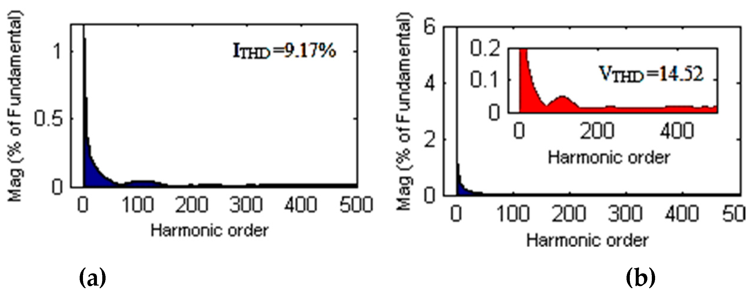
Figure 19 shows the waveforms of grid voltage Va,Vb,Vc and inverter current ia,ib,ic. The one cycle Vg and ia is given in Figure 20. Based on Figure 20 (zoomed waveform), it could realize that Vg and Iinv are meeting together in the zero crossing point for ensuring the perfect grid synchronization. The harmonics spectra of the inverter current and inverter voltage are carried out up to the 500th order (25 kHz/50Hz), as shown Figure 21; it can be seen the THD percentages for both are less, as 14.52% and 9.14%, respectively.
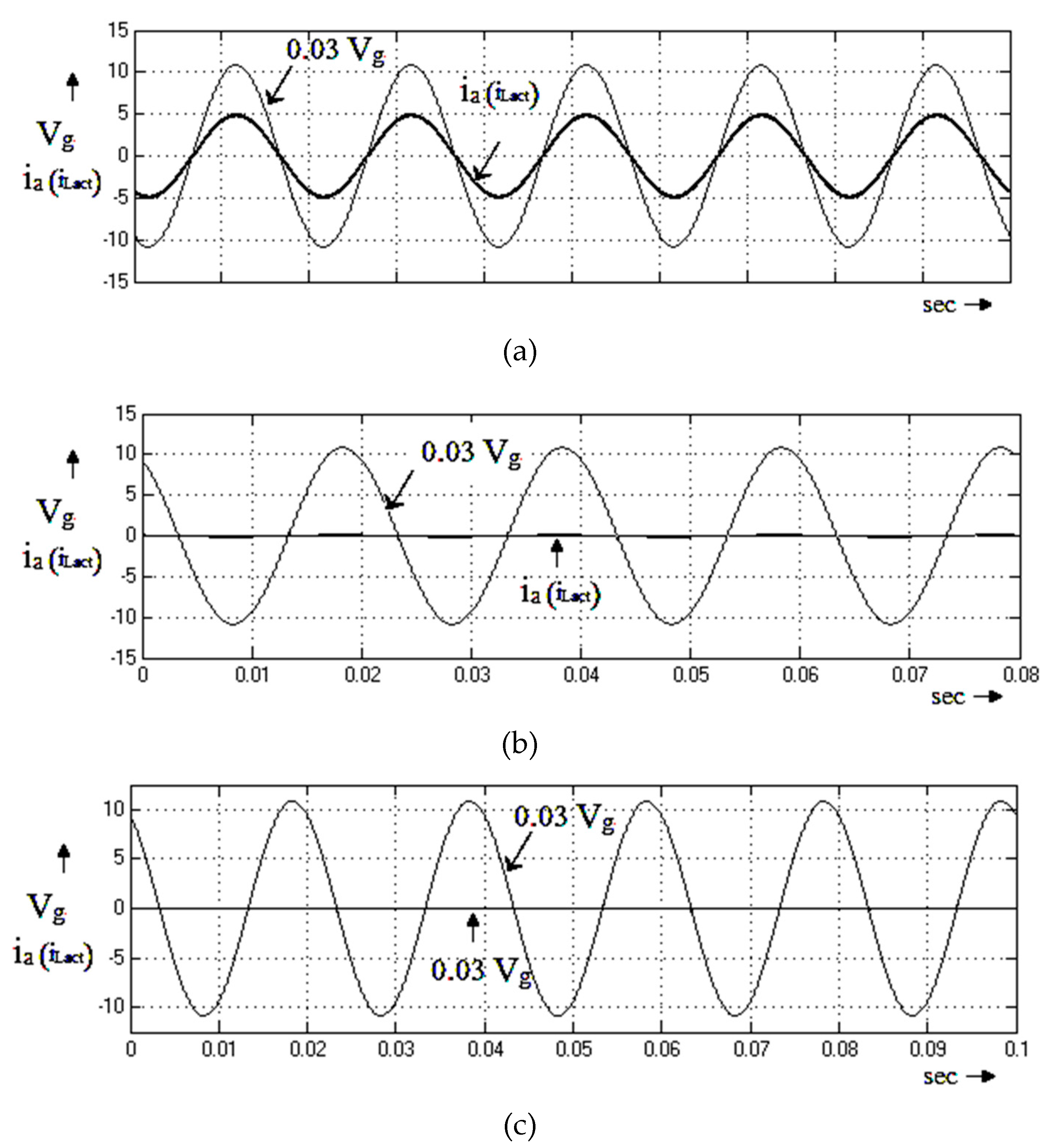
Figure 22 shows the performance of the inverter, when there is a change in grid frequency and current magnitudes, here the actual current reaches the reference current by using constant-frequency in 1/5 of the grid frequency interval itself. Figure 23 shows the leakage current of the inverter is observed as very low (100mA), which is close to zero. Based on the waveform, it could clearly understand that the proposed inverter fully mitigates the CM leakage current. Figure 24 shows the performance of the PV tied grid-connected inverter in different grid variations.
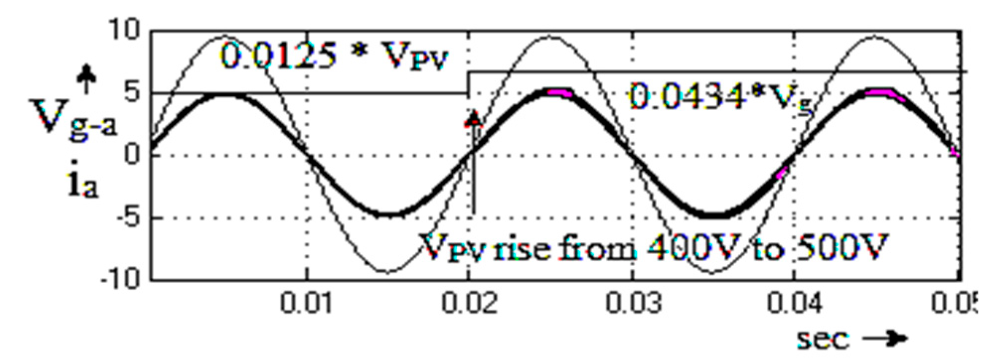
Next, the proposed system is investigated under dynamic condition, when there is an abrupt rise and drop on the grid-current, grid voltage, and PV input voltage, as shown in Figure 25 and 26. Figure 25 illustrates the performance of the PV tied grid connected TL-TMLI by a change in grid voltage Vg. Here, the grid voltage rises at 2.2ms from 230V to 250 V. Figure 26 illustrates the PV voltage variation at 3 msec from 400V to 500V. The proposed controller operated well for both the grid voltage rise and the PV voltage rise. The same way when there are sudden changes in Vg and PV input voltage, the inverter interfacing manipulations on HCC react soon to obtain the actual current matching with the reference current.
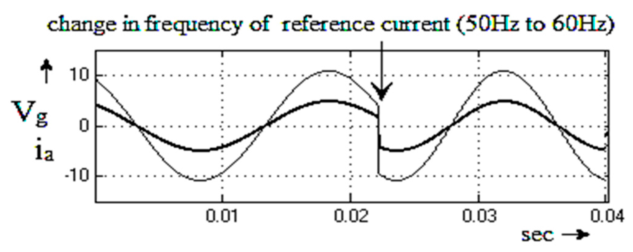
Next, the inverter performance is tested with HSVCC for different operation frequencies. Figure 27 presents the transient response of current for step change (at 0.023sec from 50Hz to 60Hz) in the frequency of the reference current. From the tested results, it is confirmed that the proposed HSVCC also exhibits superior performance in transient state.

5. Experimental Result

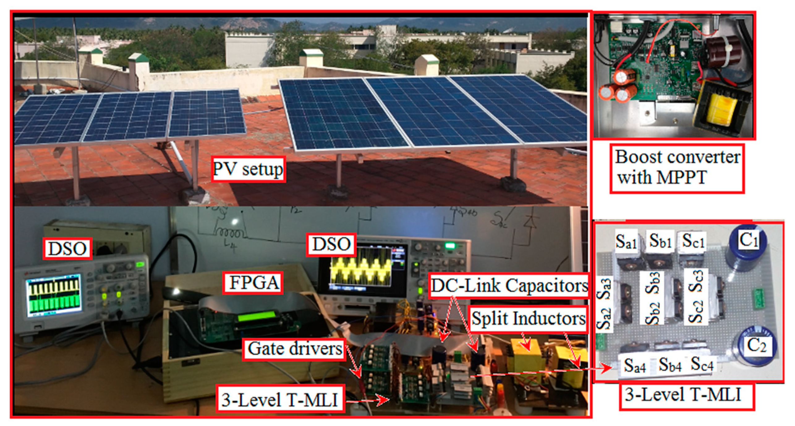
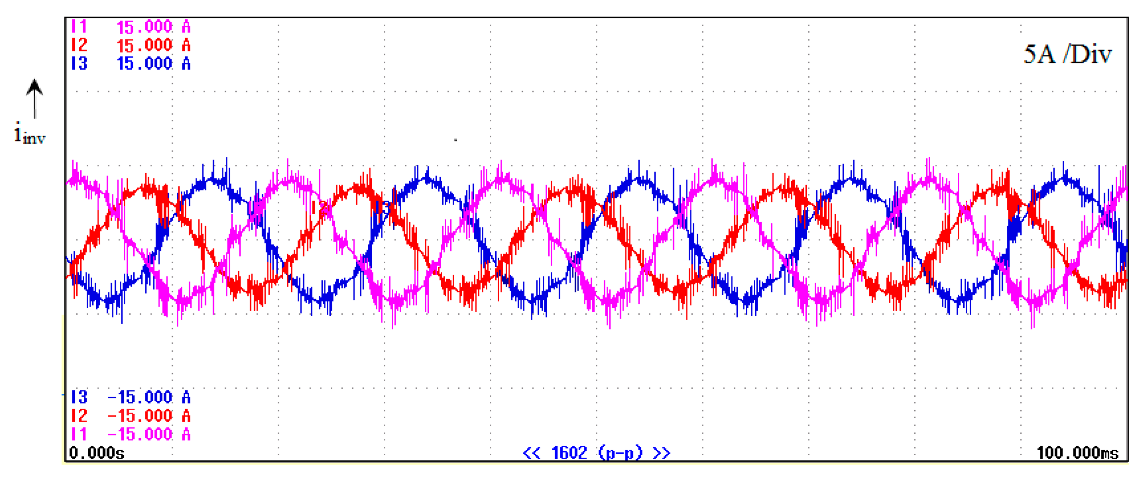
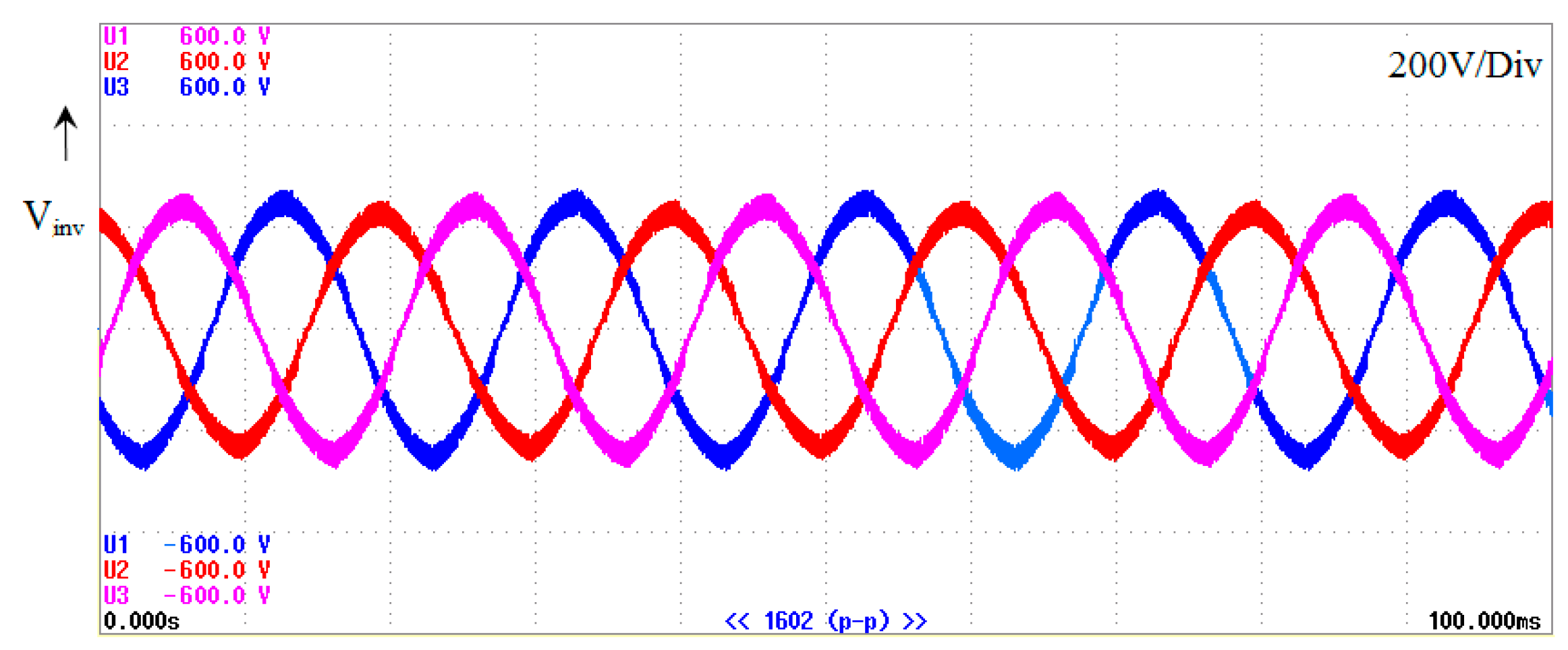
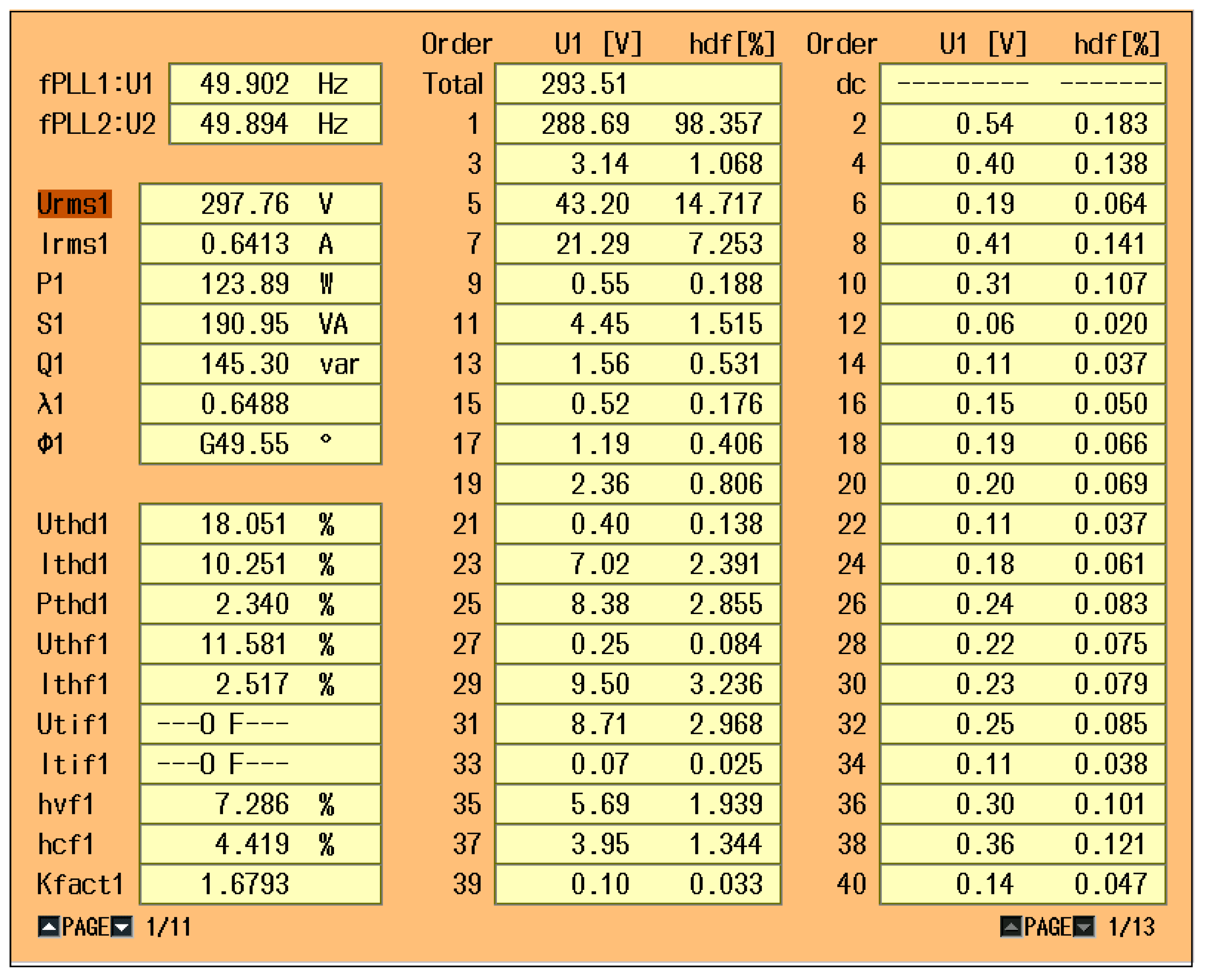
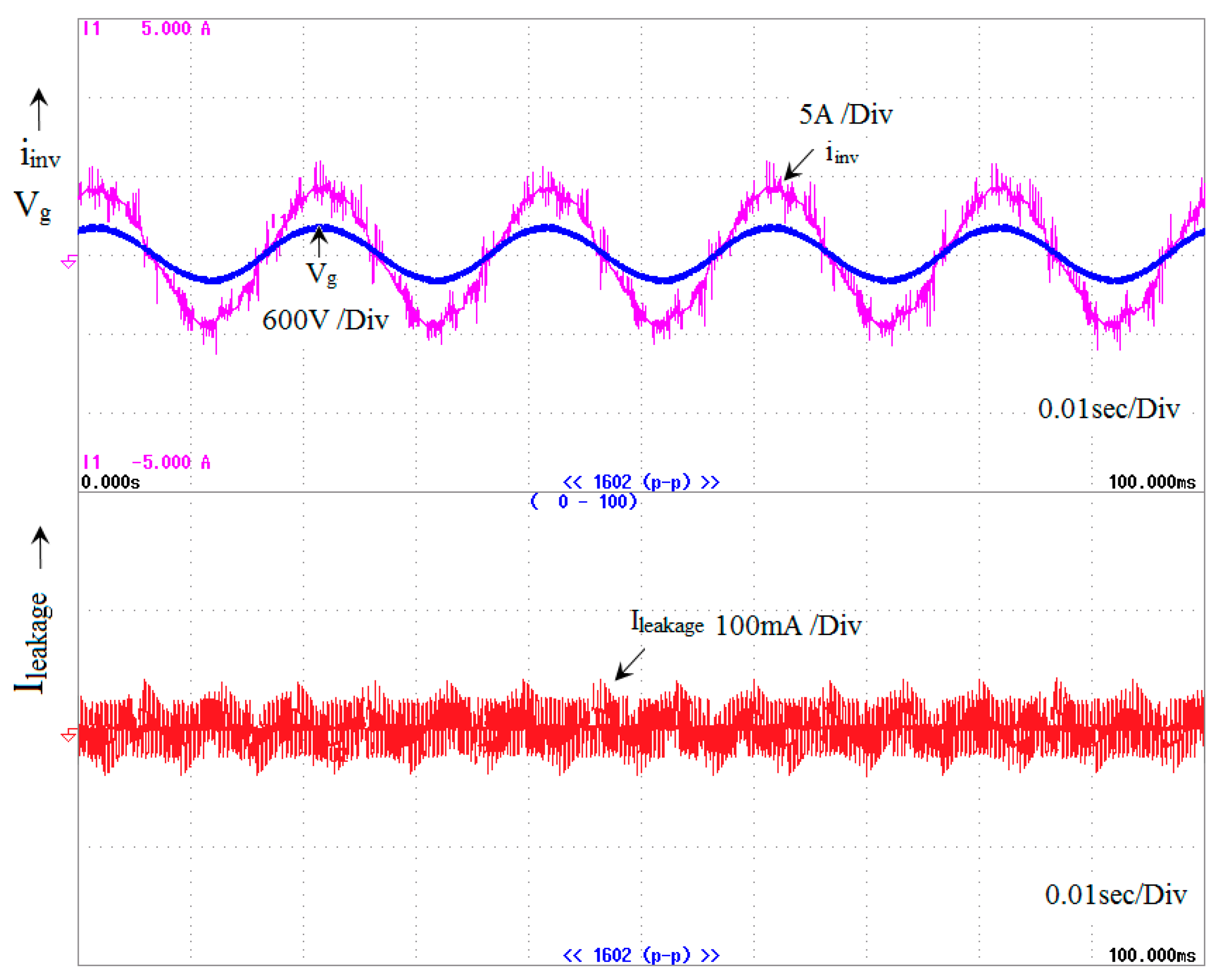
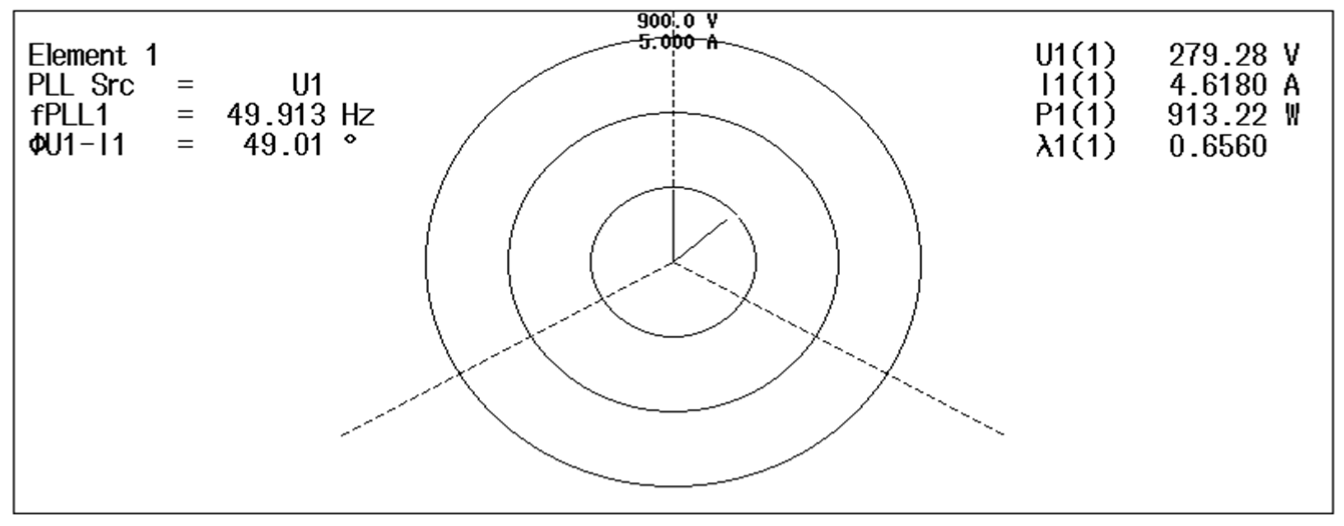
A 1.5kW prototype (shown in Figure 28) is built and CM leakage current elimination SVM signals are produced and tested on a Spartan-III field-programmable gate array (FPGA) board in order to confirm the performance of the proposed topology based 2kW roof-top PV grid connected system, which was programmed through the MATLAB/Simulink-system generated Xilinx tool. The specifications laboratory prototype proposed system parameters are listed; PV output based dc-link voltage = 400, DC-link capacitance C1=C2 = 100mF, stray capacitance (used a thin-film capacitor) =100nF, maximum ma = 0.9, output active, three phase filter inductance Lf=1mH, filter resistance Rf = 10Ω, fundamental frequency f =50Hz, switching frequency fs = 10kHz, dead time tD= 4μs. All of the collaborative results were measured by a digital oscilloscope (DSO)) Tektronix MDO4034B-3 and Yokogawa power analyzer. Figure 29 shows the phase-A inverter leg inductor currents (iL1a and iL2a). It shows that the both inductors are charged properly and identically. Similarly, other inverters phase legs -B and C inductors iL1b, iL2b andiL1c, iL2c also maintains identical nature, like phase-A inductors. Hence, the three-phase inverters currents are equal to each other. Figure 30 shows the inverter current (iinv) and Figure 31 shows the inverter voltage. The inverter current harmonics profile is measured and is given in Figure 32. Here, the percentage current THD is observed as 10.251% and all higher harmonics are eliminated. Figure 33 shows the numerical harmonics values for inverter voltage and current. From the results, it could observe that the percentage voltage THD is about 18.051. Here, the third order harmonics is predominant and all other higher orders are very low. Figure 34 shows the iL and Vg, and inverter i leakage. In order to show that the interface between Vg and iL, the Vg and IL are measured in the same scope window as 600V/div and 5A/div, respectively. Based on the waveform, it can be seen that Vg and IL are meeting together in the same zero crossing point for ensuring the grid synchronization. The second scale of Figure 34 showing leakage current of the inverter is observed as very low (200mA), which is close to zero. This value is less than the threshold value referred to VDE0126-1-1, IEC 60755, and VDE-AR-N-4105 PV tied grid connected TLI codes. Figure 35 illustrates the phasor angle of inverter and the grid voltage and current, which confirms the perfect phase sequence of inverter grid interface. With respect to PV input, the proposed PV tied gird connected T type NP-MLI transformerless topology maintains that the efficiency is more 95% in all PV conditions. Based on the above discussed experimental results of the proposed TL PV tied grid connected system, not only the removing the transformer and inverter leg leakage current. It is also ensuring the enhanced performance such as accuracy in voltage and current waveform, quicker converging speed with smaller amount of response time, no steady-state oscillation around the PVs maximum power point values.

6. Conclusions

The interested on photovoltaic tied transformerless inverter topologies and its grid interface techniques are increasingly engrossed for the benefit of high efficiency, reliability, and low cost. The main issue in the transformerless inverter is CMV, which causes the switching-frequency leakage current. The single-phase inverter and two-level topologies are well developed with additional switches and components for eliminating the CMV. Even through there are trust topologies presented in literature, MLIs based grid connected transformerless inverter topology is being researched to avail the additional benefits from MLI, such as lower device breakdown voltage, smaller harmonics effect in the output voltage, good reliability, and long life span.
With above aim, this paper has proposed three-phase three-level T type NP-MLI topology with transformerless PV grid connected proficiency. The proposed MLI is successfully connected with the PV and grid connected system with the help of improved space vector modulation technique to mitigate the CM leakage current.
First, the paper analyzed the three-phase PV tied grid connected transformerless inverter in detail and derived the mathematical model for CMV, DMV, and common mode leakage current. Subsequently, followed by CMV model, the inverter switching function equation is derived for the opportunity of leakage current mitigation. Second, the paper proposed the PV gird interfaced closed model for three-phase three-level T type NP-MLI topology with help of improved space vector modulation technique for controlling the current and mitigating the CM leakage current. The combined space vector and hysteresis current control has been proposed based on the behavior and requirements of the grid connected standards. The proposed arrangements are confirmed by MATLAB/Simulink simulations and FPGA based 1.5 kW PV tied TL-TNP-MLI grid connected experimentations. The simulation and experimental results significantly recognized that the proposed PV tied gird connected T type NP-MLI transformerless topology is observed as very low CM leakage current (200mA) for all PV and inverter operation conditions. The results are demonstrated and presented in the good stability of steady state and dynamics performances. The proposed inverter reduces current as well as voltage harmonics, and reduction leakage (current near to zero), which makes a significant reduction in harmonics filter and the complete elimination of CMV suppressions choke receptivity.

Author Contributions

All authors are involved developing the concept, simulation and experimental validation and to make the article error free technical outcome for the set investigation work.

Funding

This research received no external funding.

Conflicts of Interest

The authors declare no conflict of interest.

Abbreviations

CG-PV parasitic capacitances
VCM Common mode voltage
VDC DC-link voltage
ICM Leakage current
V* SVM Reference voltage
VZ Zero voltage vector
VS Small voltage vector
VM Medium voltage vector
VZ Large voltage vector
ITCM Total leakage current
Vα and Vβ α and β SVM coordinated voltage
iref Reference current
iact Actual current
ε i   Error current
u(t)) Control input
ma Modulation index
fs Frequency inverter switching pulse
f Grid frequency inverter switching pulse
Vg Grid voltage
ei current error
TL Transformerless inverter
TNP-MLI Neutral point multilevel inverter
SVM Space vector modulation
DMV Common mode voltage
SVD Space vector diagram
HCC hysteresis current control
HSVCC hysteresis Space vector current control
MMPT Maximum power point tracking

References

  1. Global Status Report. Renewables; REN21: Paris, France, 2018; ISBN 978-3-9818911-3-3. [Google Scholar]
  2. Zsiborács, H.; Baranyai, N.H.; Csányi, S.; Vincze, A.; Pintér, G. Economic Analysis of Grid-Connected PV System Regulations: A Hungarian Case Study. Electronics 2019, 8, 149. [Google Scholar] [CrossRef]
  3. Zsiborács, H.; Baranyai, N.H.; Csányi, S.; Vincze, A.; Pintér, G. Economic and Technical Aspects of Flexible Storage Photovoltaic Systems in Europe. Energies 2018, 11, 1445. [Google Scholar] [CrossRef]
  4. Sahan, B.; Vergara, A.N.; Henze, N.; Engler, A.; Zacharias, P. A single stage PVmodule integrated converter based on a low-power current source inverter. IEEE Trans. Ind. Electron. 2008, 55, 2602–2609. [Google Scholar] [CrossRef]
  5. Li, Q.; Wolfs, P. A review of the single phase photovoltaic module integrated converter topologies with three different dc link configuration. IEEE Trans. Power Electron. 2008, 23, 1320–1333. [Google Scholar]
  6. Lopez, O.; Freijedo, F.D.; Yepes, A.G.; Fernandez Comesana, P.; Malvar, J.; Teodorescu, R.; Doval Gandoy, J. Eliminating ground current in atransformerless photovoltaic application. IEEE Trans. Energy Convers. 2010, 25, 140–147. [Google Scholar] [CrossRef]
  7. Xiao, H.; Xie, S. Leakage current analytical model and applicationin single-phase transformerless photovoltaic grid-connected inverter. IEEE Trans. Electromagn. Compat. 2010, 52, 902–913. [Google Scholar] [CrossRef]
  8. VDE-AR-N. 4105: Power Generation Systems Connected to the Low-Voltage Distribution Network—Technical Minimum Requirements for the Connection to and Parallel Operation with Low-Voltage Distribution Networks; DIN_VDE Normo: Berlin, Germany, 2011. [Google Scholar]
  9. DIN VDE V 0126-1-1. Automatic Disconnection Device between a Generator and the Public Low-Voltage Grid; DIN VDE V 0126-1-1. Berlin, Germany, 2006. Available online: https://www.hylaw.eu/database/national-legislation/germany/din-vde-v-012611-automatic-disconnection-device-between-a-generator-and-the-public-lowv (accessed on 24 June 2019).
  10. IEEE Application Guide for Std. 1547, IEEE Standard for Interconnecting Distributed Resources with Electric Power Systems; IEEE Standard 1547.2-2008; IEEE: Piscataway, NJ, USA, 2009. [Google Scholar]
  11. IEC 61727. Photovoltaic (PV) Systems—Characteristics of the Utility Interface; IEC 61727; IEC: Geneva, Switzerland, 2004. [Google Scholar]
  12. UL 1741. Standard for Inverters, Converters, Controllers, and Interconnection System Equipment for Use with Distributed Energy Resources; UL 1741; UL: Northbrook, IL, USA, 2010. [Google Scholar]
  13. EN 61000-3-2. Electromagnetic Compatibility (EMC)—Part 3-2: Limits—Limits for Harmonic Current Emissions (Equipment Input Current Under 16 A Per Phase); EN 61000-3-2: Brussels, Belgium, 2006. [Google Scholar]
  14. Steca Grid. Available online: www.steca.com (accessed on 24 June 2019).
  15. Goodway. Available online: www.goodwe.com (accessed on 24 June 2019).
  16. Goodrich, A.; James, T.; Woodhouse, M. Residential, Commercial, Utility-Scale Photovoltaic (PV) System Prices in the United States: Current drivers and Cost-Reduction Opportunities; Nat. Renewable Energy Lab.: Golden, CO, USA, 2012.
  17. Feldman, D.; Margolis, R.; Bolinger, M.; Chung, D.; Fu, R.; Seel, J.; Wiser, R. Photovoltaic System Pricing Trends: Historical, RecentNear-Term Projections, 2013th ed.; U.S. Dept. Energy: Oak Ridge, TN, USA, 2013.
  18. Koutroulis, E.; Blaabjerg, F. Design optimization of transformerless grid-connected PV inverters including reliability. IEEE Trans. Power Electron. 2013, 28, 325–335. [Google Scholar] [CrossRef]
  19. Rodriguez, J.; Bernet, S.; Steimer, P.K.; Lizama, I.E. A survey on neutral-point-clamped inverters. IEEE Trans. Ind. Electron. 2010, 57, 2219–2230. [Google Scholar] [CrossRef]
  20. Bharatiraja, C.; Jeevananthan, S.; Munda, J.L.; Latha, R. Improved SVPWM vector selection approaches in OVM region to reduce common-mode voltage for three-level neutral point clamped inverter. Int. J. Electr. Power Energy Syst. 2016, 79, 285–297. [Google Scholar] [CrossRef]
  21. Selvaraj, R.; Chelliah, T.R.; Khare, D.; Bharatiraja, C. Fault Tolerant Operation of Parallel-Connected 3L-Neutral-Point Clamped Back-to-Back Converters Serving to Large Hydro-Generating Units. IEEE Trans. Ind. Appl. 2018, 54, 5429–5443. [Google Scholar] [CrossRef]
  22. Maheshwari, R.; Munk-Nielsen, S.; Busquets-Monge, S. Design of neutral-point voltage controller of a three-level NPC inverter with small DC-link capacitor. IEEE Trans. Ind. Electron. 2013, 60, 1861–1871. [Google Scholar] [CrossRef]
  23. Bharatiraja, C.; Jeevananthan, S.; Latha, R. FPGA based practical implementation of NPC-MLI with SVPWM for an autonomous operation PV system with capacitor balancing. Int. J. Electr. Power Energy Syst. 2014, 61, 489–509. [Google Scholar] [CrossRef]
  24. Bharatiraja, C.; Jeevananthan, S.; Latha, R. Vector Selection Approach-based Hexagonal Hysteresis Space Vector Current Controller for a Three-phase Diode Clamped MLI with Capacitor Voltage Balancing. IET Power Electron. 2016, 9, 1350–1361. [Google Scholar] [CrossRef]
  25. Yong Wang, W.W.; Shi, N.X.; Wang, C.M. Diode-Free T-Type Three-Level Neutral-Point-Clamped Inverter for Low-Voltage Renewable Energy System. IEEE Trans. Ind. Electron. 2014, 61, 6168–6174. [Google Scholar] [CrossRef]
  26. Schweizer, M.; Kolar, J.W. Design and implementation of a highly efficient three-level T-type converter for low-voltage applications. IEEE Trans. Power Electron. 2013, 28, 899–907. [Google Scholar] [CrossRef]
  27. Chokkalingam, B.; Bhaskar, M.S.; Padmanaban, S.; Vigna, K.R.; Iqbal, A. Investigations of Multi-Carrier Pulse Width Modulation Schemes for Diode Free Neutral Point Clamped Multilevel Inverters. J. Power Electron. 2019, 19, 702–713. [Google Scholar]
  28. Bharatiraja, C.; Sanjeevikumar, P.; Blaabjerg, F. Critical Investigation and Comparative Analysis of Advanced PWM Techniques for Three-Phase Three-Level NPC-MLI Drives. Electr. Power Compon. Syst. 2018, 46, 258–269. [Google Scholar]
  29. Bharatiraja, C.; Jeevananthan, S.; Munda, J.L. Timing Correction Algorithm for SVPWM Based Diode-Clamped MLI Operated in overmodulation Region. IEEE J. Sel. Top. Power Electron. Appl. 2018, 6, 233–245. [Google Scholar] [CrossRef]
  30. Santhakumar, C.; Shivakumar, R.; Bharatiraja, C.; Sanjeevikumar, P. Carrier shifting algorithms for the mitigation of circulating current in diode clamped MLI fed induction motor drive. Int. J. Power Electron. Drive Syst. 2017, 8, 844–852. [Google Scholar] [CrossRef]
  31. Bharatiraja, C.; Raghu, S.; Rao, K.R.S. Comparative analysis of different PWM techniques to reduce the common mode voltage in three-level neutral-point- clamped inverters for variable speed induction drives. Int. J. Power Electron. Drive Syst. 2013, 3, 105–116. [Google Scholar]
  32. Lyu, J.G.; Wang, J.D.; Hu, W.B.; Wu, Z.F. Research on the Neutral-Point Voltage Balance for NPC Three-Level Inverters under Non-Ideal Grid Conditions. Energies 2018, 11, 1331. [Google Scholar] [CrossRef]
  33. Wang, Y.; Xu, Q.; Ma, Z.; Zhu, H. An Improved Control and Energy Management Strategy of Three-Level NPC Converter Based DC Distribution Network. Energies 2017, 10, 1635. [Google Scholar] [CrossRef]
  34. Chen, Z.; Yu, W.; Ni, X.; Huang, A. A new modulation technique to reduce leakage current without compromising modulation index in PV systems. In Proceedings of the 2015 IEEE Energy Conversion Congress and Exposition (ECCE), Montreal, QC, Canada, 20–24 September 2015. [Google Scholar]
  35. Zhang, L.; Sun, K.; Feng, L.; Wu, H.; Xing, Y. A Family of Neutral Point Clamped Full-Bridge Topologies for Transformerless Photovoltaic Grid-Tied Inverters. IEEE Trans. Power Electron. 2013, 28, 730–739. [Google Scholar] [CrossRef]
  36. Hashempour, M.M.; Yang, M.Y.; Lee, T.L. An Adaptive Control of DPWM for Clamped-Three-Level Photovoltaic Inverters With Unbalanced Neutral-Point Voltage. IEEE Trans. Ind. Appl. 2018, 54, 6133–6148. [Google Scholar] [CrossRef]
  37. Cavalcanti, M.C.; Farias, A.M.; Oliveira, K.C.; Neves, F.A.S.; Afonso, J.L. Eliminating leakage currents in neutral point clamped inverters for photovoltaic system. IEEE Trans. Ind. Electron. 2012, 59, 435–443. [Google Scholar] [CrossRef]
  38. Araujo, S.; Zacharias, P.; Mallwitz, R. Highly efficient single-phase transformerless inverters for grid-connected photovoltaic systems. IEEE Trans. Ind. Electron. 2010, 57, 3118–3128. [Google Scholar] [CrossRef]
  39. Albalawi, H.; Zaid, S.A. An H5 Transformerless Inverter for Grid Connected PV Systems with Improved Utilization Factor and a Simple Maximum Power Point Algorithm. Energies 2018, 11, 2912. [Google Scholar] [CrossRef]
  40. Selvamuthukumaran, R.; Garg, A.; Gupta, R. Hybrid Multicarrier Modulation to Reduce Leakage Current in a Transformerless Cascaded Multilevel Inverter for Photovoltaic Systems. IEEE Trans. Power Electron. 2015, 30, 1779–1783. [Google Scholar] [CrossRef]
  41. Lopez, O.; Teodorescu, R.; Doval-Gandoy, J. Multilevel transformerless topologies for single-phase grid-connected converters, 32nd Annual Conf. onIEEE Industrial Electronics. IECON 2006, 1, 5191–5196. [Google Scholar]
  42. Kwon, J.M.; Nam, K.H.; Kwon, B.H. Photovoltaic power conditioning system with line connection. IEEE Trans. Ind. Electron. 2006, 53, 1048–1054. [Google Scholar] [CrossRef]
  43. Bharatiraja, C.; Padmanaban, S.; Siano, P.; Leonowicz, Z.; Iqbal, A. A hexagonal hysteresis space vector current controller for single Z-source network multilevel inverter with capacitor balancing. In Proceedings of the 2017 IEEE International Conference on Environment and Electrical Engineering and 2017 IEEE Industrial and Commercial Power Systems Europe, Milan, Italy, 6–9 June 2017. [Google Scholar]
  44. Wang, J.; Zhai, F.; Wang, J.; Jiang, W.; Li, J.; Li, L.; Huang, X. A Novel Discontinuous Modulation Strategy with Reduced Common Mode Voltage and Removed DC Offset on Neutral Point Voltage for Neutral Point Clamped Three Level Converter. IEEE Trans. Power Electron. 2018, 6, 1966–1978. [Google Scholar] [CrossRef]
  45. Bae, Y.; Kim, R.Y. Suppression of Common-Mode Voltage Using a Multicentral Photovoltaic Inverter Topology With Synchronized PWM. IEEE Trans. Ind. Electron. 2014, 61, 4722–4733. [Google Scholar] [CrossRef]
  46. Hu, X.; Ma, P.; Gao, B.; Zhang, M. An Integrated Step Up Inverter Without Transformer and Leakage Current for Grid-Connected Photovoltaic System. IEEE Trans. Power Electron. 2019. [Google Scholar] [CrossRef]
  47. Lee, J.S.; Lee, K.-B. New Modulation Techniques for a Leakage Current Reduction and a Neutral-Point Voltage Balance in Transformerless Photovoltaic Systems Using a Three-Level Inverter. IEEE Trans. Power Electron. 2014, 29, 1720–1732. [Google Scholar] [CrossRef]
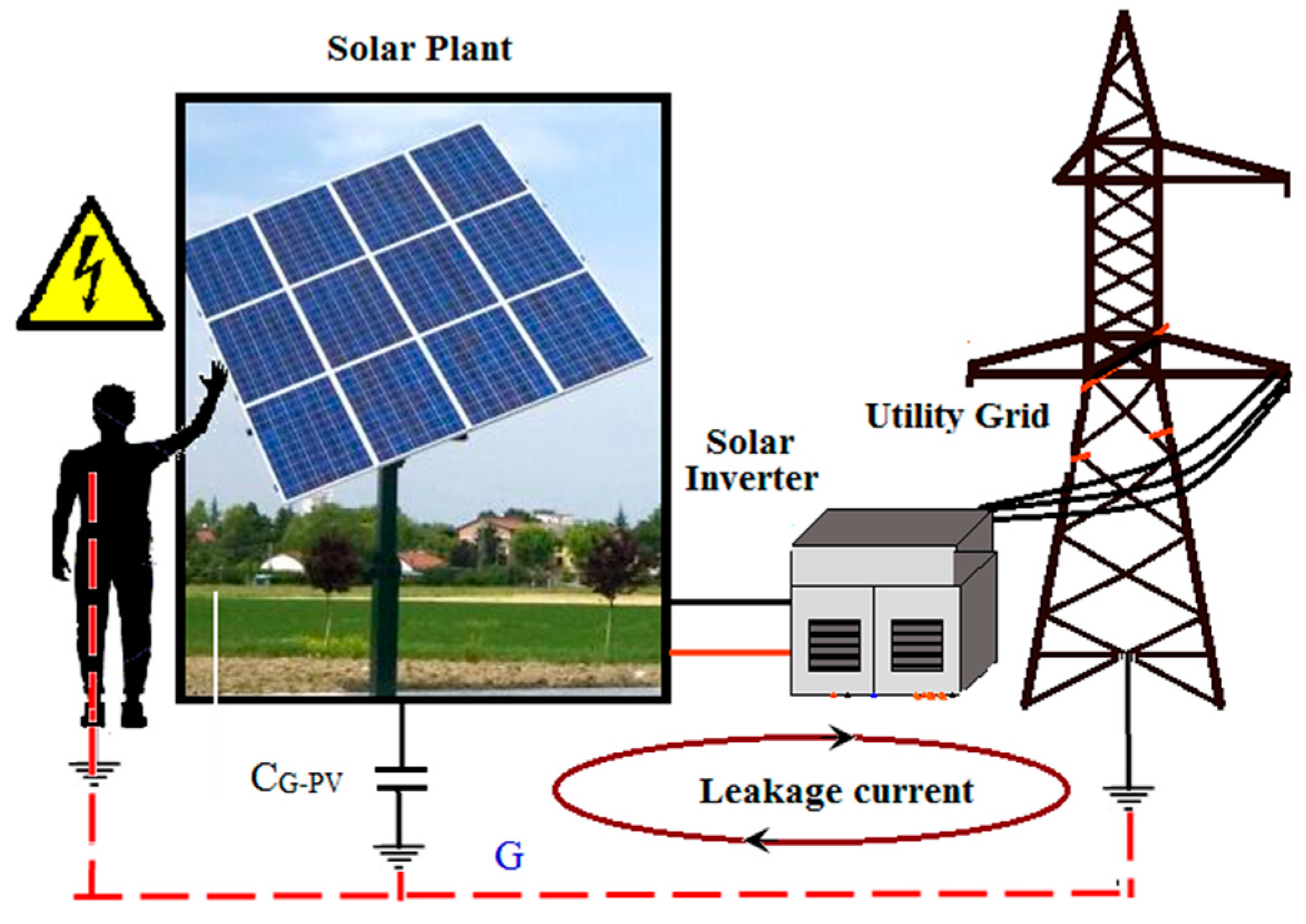
Figure 1. Leakage current for Transformerless photovoltaic (PV) connected system.
Energies 12 02434 g001
Figure 2. Grid connected PV system including the parasitic capacitance to ground of the PV array.
Energies 12 02434 g002
Figure 3. Three-phase PV-grid connected inverter model with stray elements.
Energies 12 02434 g003
Figure 4. Three-phase PV-grid connected inverter model [5].
Energies 12 02434 g004
Figure 5. PV-grid connected inverter model only A and B phase [5].
Energies 12 02434 g005
Figure 6. Single line model of total common mode voltage (CMV) [5].
Energies 12 02434 g006
Figure 7. CMV model (a) two-phase model, and (b) three-phase model.
Energies 12 02434 g007
Figure 8. PV tied Three-level TL T- MLI power circuit.
Energies 12 02434 g008
Figure 9. Three-phase space vector diagram (SVD) for three-level MLI.
Energies 12 02434 g009
Figure 10. Proposed full mitigation CMV SVD.
Energies 12 02434 g010
Figure 11. Proposed closed control PV tied grid connected TL-TMLI schematic control block.
Energies 12 02434 g011
Figure 12. Hysteresis current control (HCC) control strategy [24]. (a). HCC comparator, (b). HCC band.
Energies 12 02434 g012
Figure 13. Phase control between grid voltage Vg and inductor current iL12.
Energies 12 02434 g013
Figure 14. PV array performance for different irradiance.
Energies 12 02434 g014
Figure 15. Current error (∆ei) trajectory and controlled current trajectory in α-β plane for variable and fixed band hysteresis. (a). iLref-α and iLact-β Trajectory (b). ∆i α and ∆i β Trajectory.
Energies 12 02434 g015
Figure 16. Current error (∆ei) trajectory, and controlled current trajectory in α-β plane for variable and variable band hysteresis. (a). iLref-α and iLact-β Trajectory (b). ∆i α and ∆i β Trajectory.
Energies 12 02434 g016
Figure 17. iLact and iLref tracking; (a) variable hysteresis band, (b) variable and variable band Hysteresis.
Energies 12 02434 g017
Figure 18. Inverter leg inductor currents ( iL1 to iL6); (a) while applying fixed hysteresis band, (b) while applying variable hysteresis band.
Energies 12 02434 g018
Figure 19. Waveforms of grid voltage Va,Vb,Vc, and inverter current ia,ib,ic.
Energies 12 02434 g019
Figure 20. Vg and Iinv waveforms of proposed PV-grid connected TL-TNPC-MLI.
Energies 12 02434 g020
Figure 21. Harmonics spectra of the inverter current and inverter voltage. (a). Current THD (b). Voltage THD.
Energies 12 02434 g021
Figure 22. Performance of the PV tied grid connected TL-TMLI by change in grid current iLref.
Energies 12 02434 g022
Figure 23. Common-mode, i leakage.
Energies 12 02434 g023
Figure 24. Steady operation waveform with different grid-current command under variable-band constant-frequency HSVCC; (a) rated current, (b) 5% of rated grid current, and, (c) Zero-grid-current reference.
Energies 12 02434 g024
Figure 25. Performance of the PV tied grid connected TL-TMLI by change in grid voltage Vg.
Energies 12 02434 g025
Figure 26. Performance of the PV tied grid connected TL-TMLI by change in PV input voltage VPV.
Energies 12 02434 g026
Figure 27. Transient response of the PV tied grid-connected inverter by change grid frequency.
Energies 12 02434 g027
Figure 28. Experimental setup of PV tied reconnected tranformerless T-MLI.
Energies 12 02434 g028
Figure 29. Inverter leg inductor currents ( iL1aand iL2a).
Energies 12 02434 g029
Figure 30. Three phase inverter current (Iinv).
Energies 12 02434 g030
Figure 31. Three phase inverter voltage.
Energies 12 02434 g031
Figure 32. Inverter current ( iL) and harmonics spectra.
Energies 12 02434 g032
Figure 33. Numerical harmonics spectra of inverter voltage and inverter current.
Energies 12 02434 g033
Figure 34. Inverter current (IL) and grid voltage (Vg), and inverter leakage current.
Energies 12 02434 g034
Figure 35. Phasor angle of inverter and grid voltage and current.
Energies 12 02434 g035
Table 1. PV connected Three-level T-type MLI power circuit.
StateVoutSa1Sa2Sa3Sa4
DC++Vdc/2ONONOFFOFF
N0OFFONONOFF
DC--Vdc/2OFFOFFONON
Table 2. Mode of operation of 3L-TL-TMLI.
GroupsGroupsSwitching Mode
G-1Zero Vector (ZV) switching(000),(111),(-1-1-1)
G-2Small Vector (SV) switching{(100),(011)},{(110),(001),{(010),(101)}{(011),(100),{(001), (110)},{(101),(0-10)}
G-3Medium Vector (MV) switching(10-1), (01-1), (-110), (-101), (0-11), (1-10)
G-4Large Vector (LV) switching (1-1-1), (11-1), (-11-1), (-111), (-1-11), (1-11)
Table 3. Switching states and CMV.
GroupSwitching States of 3-Level InverterCMV Generated
A(111)Vdc/2
B(110), (101), (011)Vdc/3
C(1-11), (11-1),(-111), (001), (010), (100)Vdc/6
D(000), (01-1), (0 –11), (10-1), (1-10), (–101), (–110)0
E(– 1–11),( –11 –1), (1 –1 –1), (00 –1), (0–10), (–1 00)–Vdc/6
F(– 10 –1), (0 –1 –1), (0 –1 –1)–Vdc/3
G(–1 –1 –1)–Vdc/2