Article

A Hybrid DC Circuit Breaker with Fault-Current-Limiting Capability for VSC-HVDC Transmission System

1
School of Electronics Information and Electrical Engineering, Shanghai Jiao Tong University, Shanghai 200240, China
2
Key Laboratory of Control of Power Transmission and Conversion, Ministry of Education, Shanghai 200240, China
*
Author to whom correspondence should be addressed.
Energies 2019, 12(12), 2388; https://doi.org/10.3390/en12122388
Submission received: 28 April 2019 / Revised: 17 June 2019 / Accepted: 18 June 2019 / Published: 21 June 2019
(This article belongs to the Special Issue HVDC/FACTS for Grid Services in Electric Power Systems)

Abstract

:
The direct current circuit breakers are considered a promising option to protect the transmission line against commonly appearing line-to-ground fault. However, the challenges of losses in the nonoperational stage, escalation of response against fault current, and large fault current handling capability remain the debatable issues for direct current circuit breakers. This paper introduces a novel topology of the hybrid circuit breaker with fault-current-limiting characteristics, which contains three branches: the main branch, fault-current-limiting branch, and energy absorption branch. The main branch includes a mechanical switch, breaker impedance, and bidirectional power electronics switches. In the fault-current-limiting branch, a fault-current-limiting circuit is introduced which contains n numbers of bidirectional switches and current-limiting inductors, which are connected in series to make the design modular in nature. During the normal working stage, the current flows through the main branch of the breaker. Once a fault in the system is confirmed, the fault current is transferred to the fault-current-limiting branch. At this stage, the intensity of the fault current is reduced significantly using the fault-current-limiting circuit, and finally, the residual current is shifted to the energy absorption branch. The working principle, design considerations, and parametric analysis concerning the design of hybrid circuit breakers are incorporated in this paper. The performance of the proposed breaker is evaluated using a three-terminal voltage-source converter-based high-voltage direct current transmission network; for this purpose, a PSCAD/EMTDC simulation tool is used. The performance of the proposed breaker is also compared with other topologies. The comparative analysis shows that the proposed breaker is a good alternative considering high fault current interruption requirements, response time against fault current, and power losses.

1. Introduction

Due to increased penetration of renewable energy into power grids, the VSC-HVDC transmission projects have gained attention globally because the VSC-HVDC systems allow the independent control of active and reactive power [1,2,3,4,5]. With the passage of time, the rating of VSC-HVDC projects has increased; the details of HVDC projects in [6,7,8] strengthen this argument. The VSC-HVDC-based transmission shows more vulnerability against frequently appearing L-G faults. The increased ratings of VSC-HVDC networks demand the protection equipment with increased fault current handling capabilities.
With an increased rating of VSC-HVDC network and vulnerability towards commonly appearing L-G faults, the protection equipment is required to handle large fault current. In this context, the FCLs are generally used and classified into two types: SFCLs and NSFCLs. The studies [9,10,11,12] contain some examples under the umbrella of SFCLs; likewise, [13,14,15] present the examples of NSFCLs. The FCL of both types can limit the fault current to some extent, but the fault current cannot be forced to zero or isolated totally. Therefore, DCCBs are considered a reliable option to isolate the fault current. Generally, DCCBs are divided into three major types: mechanical active and passive resonance circuit breakers, solid-state circuit breakers (SSCB), and hybrid circuit breakers (HCBs) [16]. In 2012, a paradigm shift in the high-voltage DCCBs area was observed with the introduction of HCBs [17,18]. Later on, in 2014, another state-of-the-art HCB was introduced with experimental validation [19]. The [19] highlights the comparative analysis of two important HCBs. Although HCBs possess good features in terms of response time [17,18,19], they have limitations in handling large fault currents with increased voltage ratings. Therefore, different researchers had used the breakers in a combination of FCLs to ensure the safety, fault isolation capability, and increased fault current handling capacity as well [20,21].
In Reference [22], a compound current limiter and circuit breaker is introduced; likewise in Reference [23], the new topology for HCBs is explained in detail. In Reference [24], the implantation of breakers on a small scale is explained. The new designs of breakers placed between negative and positive terminals of line, and multiterminals are explained in [25,26,27]. Some miscellaneous protection schemes to protect the line against L-G faults using HCBs and other approaches are elucidated in [28,29]. In addition, some examples of SFCLs with DCCBs are given in [30,31], whereas the comprehensive comparison between NSFCL and SFCL is given in [32].
The recent investigations in [20,21] explain the hybridization of NSFCL and DCCB; these two examples are comprehensively elaborated here, because in the later stages, some results are reproduced for comparative analysis. In Reference [20], three breakers were used; one was called MCB, and the other two were named as BCBs. Apart from breakers, three CLIs were also used. The working principle was explained as follows: during normal operation, the CLIs were connected in parallel and thus the equivalent impedance was reduced. As a result, the on-state loss was reduced too. In case of the fault, the CLIs were used in series and had included heavy impedance during the fault current limitation stage. In this way, the intensity of the fault current was reduced. At the terminal stage, the MOAs used in the MCB and BCBs were used to absorb the residual current. The BCBs had ensured the parallel operation of current-limiting inductors during normal operating condition, and series operation in faulty condition. In Reference [21], a hybrid current-limiting circuit breaker for DC line was proposed which had two major components: energy-dissipating circuit and isolation mechanism. The energy-dissipating circuit (contains) inductance, power electronics-based switches (Thyristors), and energy-dissipating resistor. The working mechanism of the hybrid current-limiting circuit breaker was simple: in case of a fault, the intensity of the fault current was suppressed by employing current-limiting inductance, and then the main circuit was isolated using a mechanical switch. Eventually, the residual current was dissipated by the MOA and resistor.
In this paper, an improved method is developed to limit the quantum of the fault current. Similar tactics as of [20] are chosen to limit the fault current, but with significant modifications, to solve some key issues. In the previous study, to achieve the fault-current-limiting operation, two additional breakers (BCBs) were used to guarantee the series and parallel operation of the CLIs. These additional breakers had significantly increased the cost. Moreover, the CLIs remained in the circuit during normal operating condition, and as a result, the large size of inductors could result in more losses. However, using the proposed FCLC, the CLIs are only used when fault current suppression is required, and this is considered a major advantage. Thus, the use of large CLIs for high fault current handling is possible, and parallel operation of CLIs is alleviated. Since no CLI is used during normal operation, power loss in normal condition due to FCLC is zero. The schematic diagram of the proposed FCLC for DCCB is shown in Figure 1, whereas Figure 2 contains the schematic diagram of the fault current limiter discussed in [20]. In Figure 1, S1, S2, S3……Sn represent the bidirectional PE switches and L1, L2, L3……Ln represent the CLIs. By employing CLIs, the fault current can be reduced effectively; however, the main branch of the breaker has to tolerate transient overvoltage. To rectify this issue, the concept of parallel arrester is used, and the details are charted in the subsequent part of this study.
The working principle of proposed topology, analysis to determine the size of CLIs, current in different stages, and transient overvoltage analysis are discussed in Section 2 of the paper. In Section 3, simulation results are presented to verify the theoretical concepts. Section 4 contains the comparative analysis of proposed solutions with other available topologies. Finally, in Section 5, the conclusions of the paper are presented.

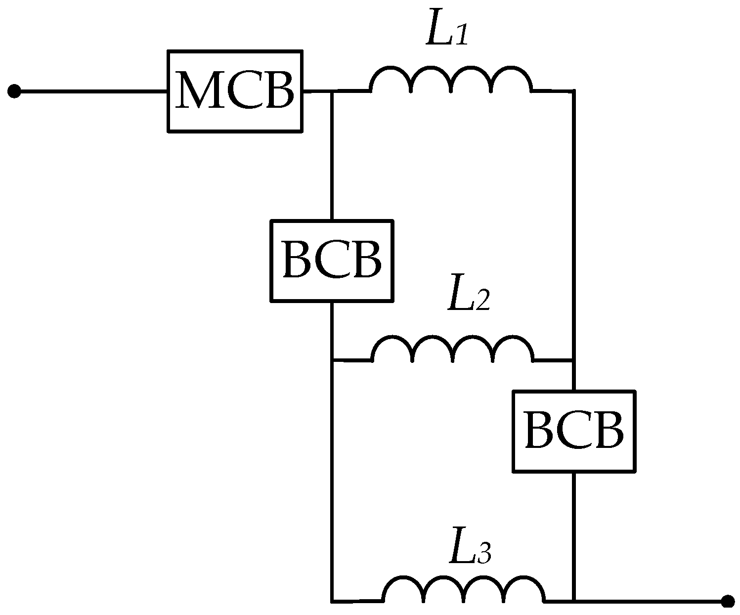
2. Proposed Topology

2.1. Working Principle

The proposed HCB with FCLC contains three branches: the main branch, auxiliary branch, and energy transfer branch, as shown in Figure 3. The main branch constitutes a mechanical switch called UFD, and bidirectional PE switches composed of IGBTs, also known as LCS. The proposed FCLC to limit the fault current is placed in the auxiliary branch. The third branch of the HCB is called the energy absorption branch, which consists of an MOA. In Figure 3, the value of CLR is represented by Lb, which is called the breaker impedance. Although the design of the FCLC is modular in nature, three CLIs are considered at this stage, namely, L1, L2, and L3, and three bidirectional PE switches composed of IGBTs are named as S1, S2, and S3. It must be noted that the CLIs are connected in series, and these are not coupled magnetically.
In order to understand the working principle of the proposed scheme and its contours, it is divided into four different working periods. The different operating periods with reference of time are shown in Figure 4. During 0 ≤ tt1, normal current flows through the whole system including the main branch of the CB. The path-I indicates the current during this interval (see Figure 5a). Normal current means the rated current of the system, defined according to design considerations. At t1, the fault in the system is suspected. After the fault is suspected, it usually takes a few milliseconds to confirm. During this time, the current continues to flow through the main branch of the CB and switches start to open gradually. The direction of current flow during this time remains the same as of 0 ≤ tt1.
Once the fault in the system is confirmed at t2, the switches associated with the main branch of the CB are opened and the fault current is directed to the FCLC placed in the auxiliary branch of the CB. At this stage, fault current limitation operation is achieved. Figure 5b explains the current flow during t2tt3. After t3, the switches in the auxiliary branch are opened and the residual fault current is shifted to the MOA. At this stage, the fault current is forced to zero and isolated from the system. The flow of current during this period is elucidated in Figure 5c.

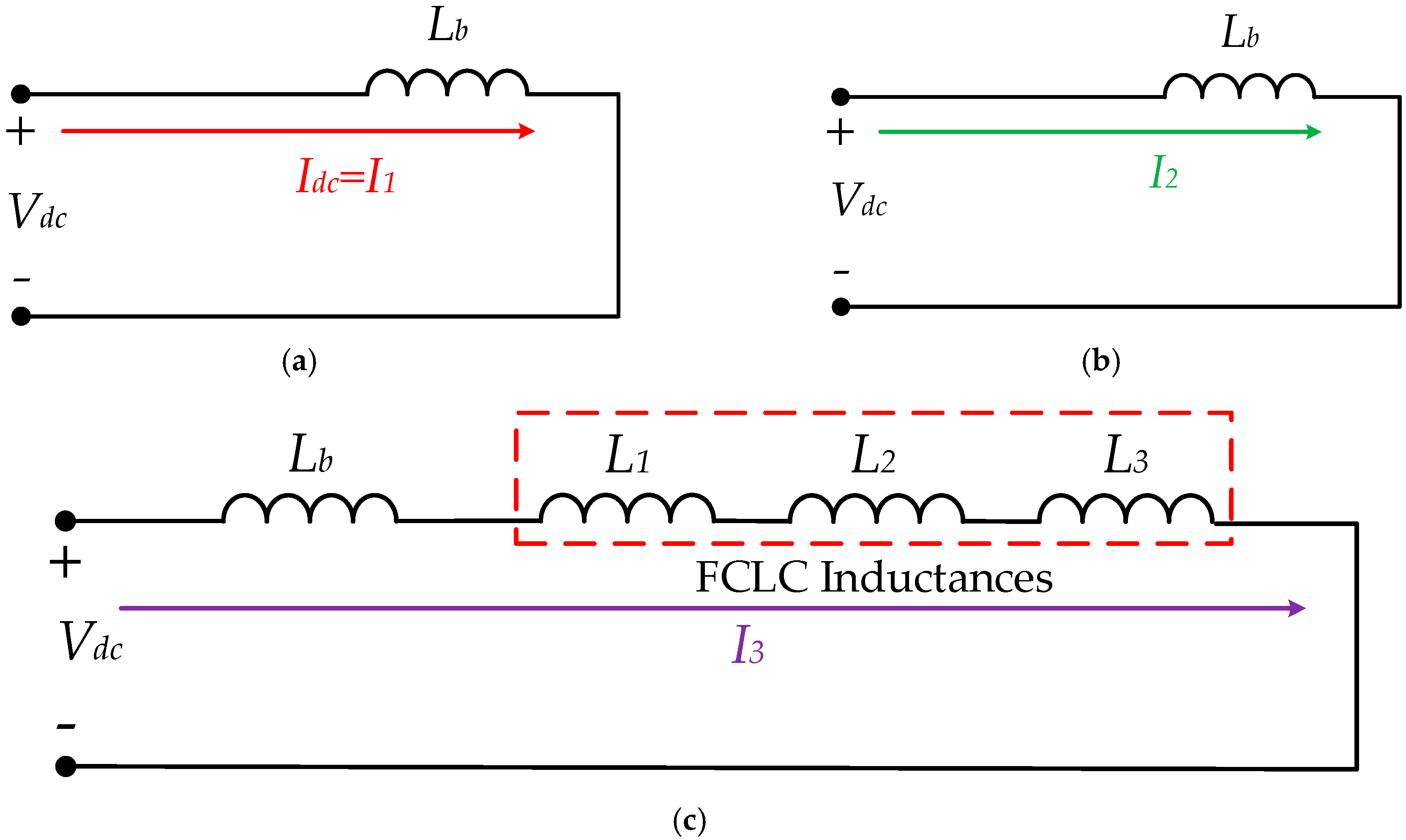
2.2. Determination of Current and Size of Current-Limiting Inductors

The size of breaker impedance (CLR/Lb) and current-limiting inductances (CLIs, L1, L2, and L3) depends on design considerations or the desired requirements. The equivalent circuit to estimate the values of current, CLR, and CLIs is divided into two parts: an equivalent circuit of the system before the fault and an equivalent circuit of the system after the fault. The equivalent circuits for the time intervals 0 ≤ tt1 and t1tt2 are shown in Figure 6a,b, respectively. The internal resistance of UFD and LCS is minimal, therefore, for simplicity, these are ignored. The second equivalent circuit is drawn for the fault current limitation stage during the time t2tt3 and is shown in Figure 6c.
During 0 ≤ tt1, the value of the current increases from zero to the rated value. This rated value is considered as the line current which is predefined. The current during this period is defined by Equation (1). In Equation (1), Idc represents the rated value of the line current.
I I = I d c
Once the fault in the system at t2 is detected, it takes a few milliseconds to confirm the existence of the fault. During this time, the current continues to flow through the main branch of the CB, and the quantum of the fault current in this interval is calculated using the equivalent circuit in Figure 6b. The current during t1tt2 is calculated with the application of KVL and Laplace Transformation. The final result is given obtained in the time domain, which is given by Equation (2).
I 2 = I I + ( V d c L b ) t
In Equation (2), I1 is the constant which depends on the initial condition, Vdc is the rated line voltage, and Lb represents the value of CLR. In Equation (2), the constant I1 is accessed by using Equation (1). From Equation (2), an approximate value of Lb can be calculated, keeping in view the maximum permissible range of fault current I2, which is the peak value of the current the system attains after fault detection. Once the fault is confirmed at t2, the FCLC in the auxiliary branch is activated. For this case, the equivalent circuit diagram is shown in Figure 6c. The following constraints are considered for calculating the current during this period:
L 1 = L 2 = L 3 = L
Application of KVL for the circuit in Figure 6c results in the following equation:
V d c = L b ( d I 3 d t ) + 3 L ( d I 3 d t )
or
V d c = d I 3 d t ( L b + 3 L )
Solving Equation (5) to get the current during the time t2tt3:
I 3 = I 2 L r L b + 3 L + V d c L b + 3 L ( t )
or
I 3 = 1 L b + 3 L [ I 2 L b + V d c ( t ) ]
In Equation (7), the current I2 depends on the initial conditions. From Equation (3), it is obvious that I2 is the maximum permitted current after fault detection. Since I3 represents the amount of suppressed current, Equation (7) is used to estimate the values of inductances (L1 = L2 = L3 = L) used during the fault current limitation stage. After the time t3, the residual current I3 is transferred to the energy absorption branch (i.e., MOA) and the fault current at this stage is converged to zero and isolated from the system. The energy absorbed by the MOA at the final stage is calculated using the following mathematical relationship [33]:
E = V ( t ) I ( t ) d t
In Equation (8), E represents the energy absorbed by the MOA, V(t) represents the voltage across the MOA, and I(t) represents the current through the MOA. The graphical illustration of DC current explaining the behavior of the current in different stages is highlighted in Figure 7. In Figure 7, tfc represents fault clearance time, which is calculated as:
t f c = t 4 t 2
Based on the above analysis, it can be concluded that the transfer of current from one branch of the breaker to another branch at the switching instants t1, t2, t3, and t4 depends on two factors: maximum values of the current and time to attain it. In other words, it depends on rate of change of the current.

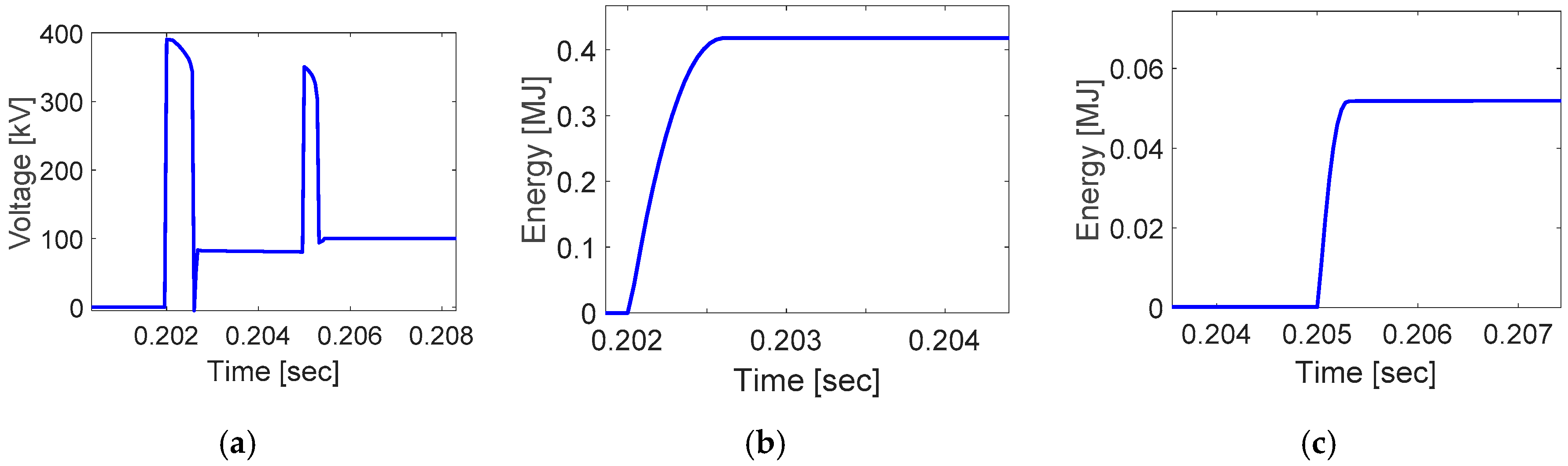
2.3. Transient Overvoltage Analysis

By application of FCLC in the auxiliary branch of the proposed HCB, the quantum of the fault current can be reduced effectively. However, due to the use of FCLC in the auxiliary branch, the main branch of the breaker has to sustain voltage overshoot for a brief time. To avoid this problem, the protection scheme for the main branch is essential. In this context, several approaches are discussed in the literature. For example, in Reference [34], the concept of parallel MOA was used to guard PE switches against overvoltage; the schematic layout is shown in Figure 8, where Rs and Ls represent system resistance and inductance, respectively, Lp represents stray inductance that exists between IGBT switch and main arrester (MOAm), and Vdc represents the terminal DC voltage. The components with dotted lines are used to protect the IGBT switch against overvoltage. A similar approach as discussed in [34] was utilized to protect the switches in the main branch against transient overvoltage; the schematic layout is given in Figure 9.

3. Results and Discussion

The proposed HCB with FCLC is tested with a three-terminal VSC-HVDC transmission system, using PSCAD/EMTDC simulation tool. The VSC is based on a two-level converter with the standard double-loop control scheme for each terminal. The schematic layout of the system with the placement of HCB is elucidated in Figure 10. The details of parameters for each terminal are given in Table A1 in the Appendix A [21]. The details of parameters used for the proposed HCB with FCLC for preliminary simulation analysis are available in Table A2 in the Appendix A. To test the performance of the proposed HCB with FCLC, the L-G fault on cable 12 is introduced. The proposed breaker to limit and isolate the fault current is commissioned on either side of the transmission line. The overall response DC current with the placement of the proposed breaker is shown in Figure 11. It must be noted that the performance of the proposed HCB is analyzed for 200 kV voltage level. This voltage level is used in various real-world projects; for example, the Zhoushan five-terminal VSC-HVDC project in China is designed for 200 kV voltage level. Thus the simulation results provide a good assessment considering the real-world applications and operating conditions.
The details of the events for the particular result are as follows. From 0 to 0.2 s, the system is allowed to operate in normal or steady-state condition. During this time, the system carries the rated DC current, which is defined as 0.5 kA. At 0.2 s (say, t1), the L-G fault is introduced on cable 12. It can be observed from the result in Figure 11 that the fault current increases with a high rate, and at 0.202 s (say, t2), the fault current reaches the level of approximately 4 kA. During this interval, the fault current is allowed to flow though the main branch of the breaker.
At 0.202 s, the fault in the system is considered confirmed, and the fault-current-limiting operation begins, by opening the switches in the main branch and closing the switches in the FCLC (in auxiliary branch). The FCLC remains alive for 3 milliseconds and the fault current first drops sharply and then at 0.205 s, it reaches the value of less than 3 kA. In this way, by employing the FCLC, the fault current is reduced significantly. After 0.205 s (say, t3), the switches in the FCLC are opened and the residual current is shifted to the MOA, and at the instant t4, the fault current is fully isolated from the system.
The supplementary results include the current though the main branch, auxiliary branch, and energy absorption branch of the breaker; these results are shown in Figure 12a–c, respectively. These results segregate the response of the DC current during different intervals. For example, in Figure 12a, the current through the LCS is outlined, which shows that from 0 to 0.202 s, the current flows through the main branch, and at 0.202 s, the switches open completely and the current drops to zero. Likewise, from Figure 12b, it can be observed that the FCLC remains inactive until 0.202 s, and after that, the fault-current-limiting operation begins, and due to the three CLIs, the current in this branch is restricted to 1.5 kA (approximately). At 0.205 s, the switches in the FCLC open and the current in the branch is dropped to zero. Right after 0.205 s, the residual current is shifted to the MOA, which is shown in Figure 12c.
Furthermore, the result in Figure 13a represents the voltage across the circuit breaker. It is important to note that all branches in the circuit breaker are connected in parallel, so the voltage across them is the same. To avoid voltage overshoot across the main branch of the circuit breaker, due to parasitic inductance and CLIs in the auxiliary branch of the breaker, an MOA of larger size (MOAov) is used with the main branch of the breaker, as discussed in [34]. This MOA shares some part of the energy in the fault current limitation stage and also resists the voltage overshoot across the main branch of the breaker in order to reduce the quantum of the fault current. From Figure 13a, it can be noted that the voltage overshoot is observed twice, first when the fault-current-limiting operation begins at 0.202 s, and secondly at 0.205 s, when the residual current is transferred to the MOA. Figure 13b,c show energy absorbed by overvoltage arrester (MOAov) and main arrester (MOAm), respectively.
Moving forward, the impact of varying the values of current-limiting inductances (L1 = L2 = L3 = L) in the FCLC is also observed, keeping all other parameters unchanged, and Figure 14 shows the overall response of the DC current. It is observed from the results that the larger values of inductances lower the rate of increase of the current and also improve the fault clearance time (i.e., tfc). In addition, the peak value of the current during the fault current limitation stage reduces with larger L. Figure 15a,b show the corresponding energy absorbed by overvoltage arrester (MOAov) and main arrester (MOAm), respectively. The quantified data of system response under varying values of L is given in Table 1.

4. Comparative Analysis of Proposed Breaker and Other Topologies

So far, the critical results of the proposed HCB with FCLC under various conditions have been discussed. In this segment of the paper, the performance of the proposed HCB with FCLC is compared with other solutions to evaluate the effectiveness and competitiveness. For this purpose, a three-terminal VSC-HVDC model is used, with the same parameters discussed in Table A1 in the Appendix A. The designs of the proposed FCLC and current-limiting breaker in [20] are modular in nature, therefore the number of CLIs can be changed according to requirements; for compression purpose, one CLR and three CLIs are used. The details of breaker parameters used for compression purpose are the same as in Table A2 in the Appendix A.
The results presented in Figure 16 signify the DC current flowing through the systems for three different cases. The results in Figure 17 show the response of voltage across the breaker, and Figure 18 shows the power absorbed by the main arrester for different solutions. The details of the results discussed in Figure 16 are as follows: at 0.2 s, a fault in the system is introduced, and for 2 milliseconds, the current is allowed to flow through the main branch of breaker discussed in [18,20] and proposed scheme. It is observable that during this time, the rate of increase of the current and maximum value of current for [18] and the proposed scheme is the same. However, in the same interval, the rate of increase of the fault current is less for the solution discussed in [20], and the maximum value of the current is also a bit lower. Because the CLIs are used in parallel even in normal condition, they resist the steep increment in the fault current during fault confirmation stage.
The fault-current-limiting operation is applied for 3 milliseconds. During the fault current limitation stage, the current starts to flow through the auxiliary branch of the breaker in [18,20] and the proposed scheme. Since the design of the breaker in [18] has no capacity to limit the fault current, during this interval, the current continues to increase and reaches the peak value of 8 kA (approximately). For [20], during this time, the intensity of the fault current is first reduced and then increased to the level of 2 kA (approximately). In the proposed scheme, the FCLC is employed in the auxiliary branch, and thus the fault current is first dropped and then increased to 1.4 kA (approximately).
The details of results concerning voltage across the breaker in Figure 17 is as follows. From 0 to 0.2 s, the voltage across the breaker is zero for all cases because during this time, the system is operating in normal condition. At 0.2 s, a fault in the system is introduced for the proposed HCB, and [18] the voltage remains zero until 0.202 s, because for 2 ms after the introduction of the fault, the current continues to flow through the main branch of the breaker. For Reference [20], the voltage across the breaker is also observed during fault confirmation stage due to the use of parallel CLIs. At 0.202 s, the fault current limitation starts; the transient voltage overshoot is large for Reference [20], however, it can be compensated using capacitors in parallel with BCBs. For the proposed HCB with FCLC, the transient voltage overshoot is controlled using the concept of parallel arresters as mentioned in [34]. The voltage across the breaker discussed in [18] remains zero during the fault-current-limiting stage because no fault-current-limiting component is used. The second voltage overshoot is observed when the current is shifted to the main MOA at the final stage. From Figure 17, it can be observed that during this stage, voltage across the proposed HCB is better than the other two cases. The results in Figure 18 show the power absorbed by the main arrester under different causes, and it is clear that the main arrester in the proposed HCB absorbs the energy less than the others. The performance evaluation charts in Table 2 and Table 3 summarize the details of comparative analysis.
From the details of the performance evaluation charts in Table 2 and Table 3, it is established that the proposed HCB with FCLC can prove to be a good alternative to limit and isolate the fault current in VSC-HVDC transmission systems.

5. Conclusions

A novel topology of HCB is proposed in this paper, with additional characteristics to limit the fault current. The main branch of the breaker is constituted by using UFD and IGBT switches, as used in several other topologies discussed in the literature. In the auxiliary branch, a new circuit named FCLC is introduced. During the fault current suppression stage, the intensity of the fault current is reduced by using FCLC. The reduction in the fault current can cause transient voltage overshoot, which is reduced by using a parallel asserter in the main branch. During fault current limitation, a portion of energy is absorbed by the asserter used for overvoltage protection, thus the requirement for the main asserter is also reduced. The values of CLR and inductances in FCLC can be designed by considering the following aspects: cost, the maximum permissible range of fault current, the required level of fault current suppression, and fault clearance time. A larger size of CLI can reduce the fault current more quickly, but it also causes transient voltage overshoot; consequently, the requirement for protection equipment in the main branch of the breaker also increases, thus a smaller size of CLI is recommended. The simulation results for different case studies and comprehensive comparative analysis indicate that the proposed HCB with FCLC can prove to be a good alternative to limit and isolate the fault current with reasonable efficiency.

Author Contributions

The author M.A. presented the core idea of this paper. Furthermore, he had done the numerical analysis and all simulation-based experiments. W.Z. suggested the pertinent literature for review and supervised the whole process of write-up.

Funding

Authors would like to acknowledge the following agencies for their support: Project Supported by National Key R&D Program of China (2018YFB0904600); and Special Funding of Technical Standard of Shanghai Science and Technology Commission (18DZ2205700).

Conflicts of Interest

The authors declare no conflict of interest.

Abbreviations

BCCBBranch circuit breakerLCCLine-commutated converters
CLRCurrent-limiting reactance LCSLoad commutation switch
CLIsCurrent-limiting inductorsL-GLine-to-ground
CBCircuit breaker MOAMetal oxide arrester
DCDirect currentMCBMain circuit breaker
DCCBDirect current circuit breakermsMilliseconds
FCLCFault-current-limiting circuitMJMegajoule
FCLFault current limiters NSFCLsNon-superconducting FCL
HVDCHigh-voltage direct current PEPower electronics
HVAC High-voltage alternating currentSFCLsSuperconducting FCL
HCBHybrid circuit breaker VSCVoltage source converter

Appendix A

Table A1. Three-terminal VSC-HVDC parameters.
ParametersValues
DC link parametersDC voltage Vdn±200 kV
DC current Idn0.5 kA
DC link capacitor300 µF
Active powerTerminal-1 (P1)0 MW
Terminal-2 (P2)+200 MW
Terminal-3 (P3)−200 MW
DC line parametersLength of cable 12200 km
Length of cable 13100 km
Resistance per unit length (R)0.035 Ω/kM
Inductance per unit length (L)0.156 mH/kM
AC gridGrid-1 voltage420 kV
Grid-2 voltage500 kV
Grid-3 voltage420 kV
Table A2. Proposed HCB with FCLC parameters.
ParametersValues
CLRLb38.4 mH
CLIsInductor-1 L1100 mH
Inductor-2 L2100 mH
Inductor-3 L3100 mH
Parasitic inductance L’p2 µH

References

  1. Zappa, W.; Junginger, M.; van den Broek, M. Is a 100% renewable European power system feasible by 2050? Appl. Energy 2019, 233–234, 1027–1050. [Google Scholar] [CrossRef]
  2. The International Renewable Energy Agency (IRENA). Renewable Energy Statistics 2018. Available online: http://www.ren21.net/wp-content/uploads/2018/06/17-8652_GSR2018_FullReport_web_final_.pdf (accessed on 1 March 2019).
  3. World Economic Forum (WEF). Three Countries Are Leading the Renewable Energy Revolution. Available online: https://www.weforum.org/agenda/2018/02/countries-behind-global-renewable-energy-growth/ (accessed on 1 March 2019).
  4. Renewable Energy Network (REN) for the 21st Century. Renewables 2018 Global Status. Available online: http://www.ren21.net/wp-content/uploads/2018/06/17-8652_GSR2018_FullReport_web_final_.pdf (accessed on 1 March 2019).
  5. Rudervall, R.; Charpentier, J.P.; Sharma, R. High Voltage Direct Current (HVDC) Transmission Systems Technology Review Paper. Presented at the Energy Week 2000, Washington, DC, USA, 7–8 March 2000. [Google Scholar]
  6. Muhammad Rashid. In Power Electronics Hand Book, 4th ed.; BH Publications: Oxford, UK, 2018; pp. 849–851.
  7. ABB. High-Voltage Direct Current Transmission Enabling Single EU Energy Market. Available online: http://www.eem18.eu/gfx/eem-network/userfiles/_public/eem18_lodz_krontiris.pdf (accessed on 1 March 2019).
  8. IEEE Transmission and Distribution Committee. HVDC Project Listing. Available online: http://www.ece.uidaho.edu/hvdcfacts/Projects/HVDCProjectsListingDec2006.pdf (accessed on 1 March 2019).
  9. Yang, Q.; Le Blond, S.; Liang, F. Design and Application of Superconducting Fault Current Limiter in a Multiterminal HVDC System. IEEE Trans. Appl. Supercond. 2017, 27, 1–5. [Google Scholar] [CrossRef] [Green Version]
  10. Lee, H.Y.; Asif, M.; Park, K.H.; Lee, B.W. Feasible Application Study of Several Types of Superconducting Fault Current Limiters in HVDC Grids. IEEE Trans. Appl. Supercond. 2018, 28, 1–5. [Google Scholar] [CrossRef]
  11. Li, B.; Jing, F.; Li, B.; Chen, X.; Jia, J. Study of the application of active saturated iron-core superconductive fault current limiters in the VSC-HVDC system. IEEE Trans. Appl. Supercond. 2018, 28, 1–6. [Google Scholar] [CrossRef]
  12. Chen, L.; Tang, F.; Ren, L. Comparative study of inductive and resistive SFCL to mitigate the DC fault current in a VSC-HVDC system integrated with wind power farms. In Proceedings of the 2015 IEEE International Conference on Applied Superconductivity and Electromagnetic Devices (ASEMD), Shanghai, China, 20–23 November 2015. [Google Scholar]
  13. Sujuan, X.; Yufeng, Q.; Tianshu, B. Resistive DC fault current limiter. IET J. Eng. 2017, 2017, 1682–1685. [Google Scholar] [CrossRef]
  14. Wang, M.; Leterme, W.; Beerten, J.; van Hertem, D. Using fault current limiting mode of a hybrid DC breaker. IET J. Eng. 2018, 2018, 818–823. [Google Scholar] [CrossRef]
  15. Keshavarzi, D.; Farjah, E.; Ghanbari, T. Hybrid DC Circuit Breaker and Fault Current Limiter with Optional Interruption Capability. IEEE Trans. Power Electron. 2018, 33, 2330–2338. [Google Scholar] [CrossRef]
  16. Franck, C.M. HVDC Circuit Breakers: A Review Identifying Future Research Needs. IEEE Trans. Power Deliv. 2011, 26, 998–1007. [Google Scholar] [CrossRef]
  17. Hassanpoor, A.; Häfner, J.; Jacobson, B. Technical Assessment of Load Commutation Switch in Hybrid HVDC Breaker. IEEE Trans. Power Electron. 2015, 30, 5393–5400. [Google Scholar] [CrossRef]
  18. Callavik, M.; Blomberg, A.; Häfner, J.; Jacobson, B. Break-through!: ABB’s hybrid HVDC breaker, an innovation breakthrough enabling reliable HVDC grids. Abb Rev. 2013. Available online: https://www.researchgate.net/publication/297049686_Break-through_ABB’s_hybrid_HVDC_breaker_an_innovation_breakthrough_enabling_reliable_HVDC_grids (accessed on 1 March 2019).
  19. Nguyen, A.D.; Nguyen, T.T.; Kim, H.M. A comparison of different hybrid direct current circuit breakers for application in HVDC system. Int. J. Control Autom. 2016, 9, 381–394. [Google Scholar] [CrossRef]
  20. Li, S.; Zhang, J.; Xu, J.; Zhao, C. A new topology for current limiting HVDC circuit breaker. Int. J. Electr. Power Energy Syst. 2019, 104, 933–942. [Google Scholar] [CrossRef]
  21. Liu, J.; Tai, N.; Fan, C.; Chen, S. A Hybrid Current-Limiting Circuit for DC Line Fault in Multiterminal VSC-HVDC System. IEEE Trans. Ind. Electron. 2017, 64, 5595–5607. [Google Scholar] [CrossRef]
  22. Heidary, A.; Radmanesh, H.; Bakhshi, A. A Compound Current Limiter and Circuit Breaker. Electronics 2019, 8, 551. [Google Scholar] [CrossRef]
  23. Nguyen, V.-V.; Son, H.-I.; Nguyen, T.-T.; Kim, H.-M.; Kim, C.-K. A Novel Topology of Hybrid HVDC Circuit Breaker for VSC-HVDC Application. Energies 2017, 10, 1675. [Google Scholar] [CrossRef]
  24. Thomas, J.; Geraint, P.C.; Christian, M.F. Small-scale HVDC circuit breaker. IEEE Trans. Compon. Packag. Manuf. Technol. 2017, 7, 1058–1068. [Google Scholar] [CrossRef]
  25. Kontos, E.; Schultz, T.; Mackay, L. Multiline breaker for HVdc applications. IEEE Trans. Power Deliv. 2017, 33, 1469–1478. [Google Scholar] [CrossRef]
  26. Li, C.; Liang, J.; Wang, S. Interlink hybrid DC circuit breaker. IEEE Trans. Ind. Electron. 2018, 65, 8677–8686. [Google Scholar] [CrossRef]
  27. Liu, W.; Liu, F.; Zhuang, Y. A multiport circuit breaker-based multiterminal DC system fault protection. IEEE J. Emerg. Sel. Top. Power Electron. 2018, 7, 118–128. [Google Scholar] [CrossRef]
  28. Nadeem, M.H.; Zheng, X.; Tai, N.; Gul, M. Identification and Isolation of Faults in Multi-terminal High Voltage DC Networks with Hybrid Circuit Breakers. Energies 2018, 11, 1086. [Google Scholar] [CrossRef]
  29. Cwikowski, O.; Wood, A.; Miller, A. Operating DC Circuit Breakers with MMC. IEEE Trans. Power Deliv. 2018, 33, 260–270. [Google Scholar] [CrossRef]
  30. Xiang, B.; Liu, Z.; Geng, Y.; Yanabu, S. DC Circuit Breaker Using Superconductor for Current Limiting. IEEE Trans. Appl. Supercond. 2015, 25, 1–7. [Google Scholar] [CrossRef]
  31. Pei, X.; Cwikowski, O.; Smith, A.C.; Barnes, M. Design and Experimental Tests of a Superconducting Hybrid DC Circuit Breaker. IEEE Trans. Appl. Supercond. 2018, 28, 1–5. [Google Scholar] [CrossRef] [Green Version]
  32. Alam, M.S.; Abido, M.A.Y.; El-Amin, I. Fault Current Limiters in Power Systems: A Comprehensive Review. Energies 2018, 11, 1025. [Google Scholar] [CrossRef]
  33. Filipović-Grčić, B.; Uglešić, I.; Pavic, I. Energy Stress of Surge Arresters Due to Temporary Overvoltages. In Proceedings of the International Conference on Power Systems Transients (IPST), Delft, The Netherlands, 14–17 June 2011. [Google Scholar]
  34. Magnusson, J.; Saers, R.; Liljestrand, L.; Engdahl, G. Separation of the Energy Absorption and Overvoltage Protection in Solid-State Breakers by the Use of Parallel Varistors. IEEE Trans. Power Electron. 2014, 29, 2715–2722. [Google Scholar] [CrossRef]
Figure 1. Proposed FCLC for DCCB used in auxiliary branch of breaker.
Energies 12 02388 g001
Figure 2. Fault-current-limiting circuit with MCB and BCB.
Energies 12 02388 g002
Figure 3. Proposed HCB with FCLC.
Energies 12 02388 g003
Figure 4. Different operating periods with fault current handling stages.
Energies 12 02388 g004
Figure 5. Flow of current through different branches of breakers during different time intervals: (a) 0 ≤ tt1 and t1tt2; (b) t2tt3; (c) t > t3.
Energies 12 02388 g005aEnergies 12 02388 g005b
Figure 6. The simplified equivalent circuits in different working stages: (a) for normal working stage; (b) for fault suspect/confirmation stage; (c) for fault current limitation stage.
Energies 12 02388 g006
Figure 7. The graphical illustration of estimated DC current with control signals.
Energies 12 02388 g007
Figure 8. A scheme for protection of PE switches against overvoltage.
Energies 12 02388 g008
Figure 9. Representing the protection approach for switches in main branch of the HCB with FCLC.
Energies 12 02388 g009
Figure 10. Three-terminal VSC-HVDC system.
Energies 12 02388 g010
Figure 11. Overall response DC current.
Energies 12 02388 g011
Figure 12. Current through different branches of breaker: (a) main branch; (b) FCLC (auxiliary branch); (c) MOAm.
Energies 12 02388 g012
Figure 13. Miscellaneous results: (a) voltage across breaker; (b) energy absorbed by MOAov; (c) energy absorbed by MOAm.
Energies 12 02388 g013
Figure 14. The influene of L on overall DC current.
Energies 12 02388 g014
Figure 15. Energy absorbed by arrester under different values of L: (a) MOAov; (b) MOAm.
Energies 12 02388 g015
Figure 16. The response of DC current flowing through the system under the influence of different solutions.
Energies 12 02388 g016
Figure 17. Voltage across the breaker under influence of different solutions.
Energies 12 02388 g017
Figure 18. Power absorbed by main MOA under different solutions.
Energies 12 02388 g018
Table 1. Repressing the statistical details of system response under varying values of L.
Size of L (mH)Fault Clearance Time (ms)Peak Current in Fault Current Limitation Stage (kA)Energy Absorbed by MOAov (MJ)Energy Absorbed by MOAm (MJ)
1003.251.400.43060.052
1503.151.000.45580.024
2003.110.760.47050.014
2503.080.620.48100.009
3003.050.520.48810.006
Table 2. Performance evaluation chart for normal and fault suspect/confirmation stage.
SchemesCurrent in Normal Working StageCurrent in Fault Suspect/Confirmation Stage
I1 (max) [kA]I2 (max) [kA]Time to Attain [ms]
[18]0.53.82
[20]0.53.22
Proposed0.53.22
Table 3. Performance evaluation chart for fault current limitation and clearance stage.
SchemesCurrent in Limitation StageClearance Stage
I3 (max) [kA]Time to Attain [ms]Energy Absorbed by MOA [MJ]Clearance Attained [ms]
[18]8.2531.783.8
[20]2.0430.764.8
Proposed1.4030.053.8

