1. Introduction
Nowadays, most of the vehicles in the transportation system are still dependent on liquid fossil fuels, which are slowly being depleted. Fifty percent of crude oil production is used by vehicles in the transportation sector. The continuous consumption of liquid fossil fuels has led to increased atmospheric absorptions of greenhouse gases (GHG), especially carbon dioxide. For such reasons, shifting the global energy demand away from fossil fuels towards sustainable transportation is becoming a critical matter. In this context, full electric or hybrid road vehicles have attracted attention as good solutions to the above problems of liquid fossil fuel dependency [
1].
Electric vehicles (EVs) have become an important factor in the growth of automobile manufacturing. EVs are operated by an electric motor that receives power from a rechargeable battery. Presently, there are two charging techniques for EVs, namely AC and DC charging [
2,
3,
4,
5]. For AC charging, single-phase or three-phase AC power is supplied to an on-board AC–DC power converter in the EV. Meanwhile, DC charging is performed by directly supplying DC power to the battery of the EV via an off-board AC–DC power converter. The use of on-board chargers will definitely increase the charging accessibility of the vehicle; meanwhile, off-board chargers allow the use of higher rating circuits. Thus, the off-board charger completes the charging in a shorter period of time. An off-board charger is actually available as an external unit, rather than being a part of the EV. A typical off-board charger is able to produce a higher DC voltage. For practical purposes, a battery management system (BMS) is required to operate the battery system safely and efficiently for an extended life. The BMS is used is to provide a reliable estimate of the crucial internal states such as the state of charge (SOC) and the instantaneous capacity, which is an indicator of the State of Health (SOH) [
6]. As a result, the BMS should have the ability to charge the battery by using this voltage. Nevertheless, the main weakness of this type of design is that the charger is not installed as a part of the EV. Therefore, the charging of the EV battery can only be done with a specific charger that is capable of providing the required amount of DC voltage. In contrast to an off-board charger, an on-board charger is a part of the EV, which allows for charging at almost any location possible as long as single-phase or three-phase supply is available.
Owing to the advancements in EV technologies, the design of a reliable, efficient, and high power density charger has become a great challenge. One of the common issues with EV charging is the use of power electronics converters that potentially create harmonics issues in the grid. These harmonics have impacts on the power quality (PQ) of the low-voltage (LV) distribution network. They can negatively affect the stability as well [
7,
8]. Furthermore, the input current of an EV charger with high total harmonic distortion (THD) can subsequently cause many problems for the other electronic devices that are used in the charger station. As the level of harmonics increases within the supply, there can be unwanted side effects in the charging stations, such as conductor and transformer heating. In addition, the harmonic current levels can cause voltage distortion in the supply, which may also cause unwanted effects for other electrical equipment connected to the same mains supply. Moreover, the chargers also suffer from high ripples of DC-link voltage which can damage the battery. The existing battery chargers are designed to charge only one level of the charging mode. Therefore, there is a lack of flexibility in terms of providing multi-modes charging. Level 1 charging can draw 1.4–1.9 kW of power based on the ampere rating, while the time required to fully charge the battery of an EV is 6–8 h [
9]. The required power of Level 2 charging is 7.7–25.6 kW, and it commonly takes 4–8 h to fully charge [
10]. The output power of Level 3 charging is 50–100 kW, and it requires 1–3 h to fully charge the battery of a heavy-duty-vehicle [
11,
12].
Various control algorithms have been developed to charge EVs. These control algorithms have been introduced to limit the harmonic content of the current drawn from the power line by the rectifiers, such as direct power control (DPC) [
13], but this type of controller needs high inductance and sample frequency. In [
14], hysteresis control, originally used for thermostatically controlled loads [
15], is employed for plug-in electric vehicle (PEV) charging to actively control the aggregated consumption of a higher number of chargers. However, variable switching frequency and the possibilities of limit cycle operation with high-frequency switching are the disadvantages of this type of controller.
In addition, numerous studies have established that model predictive control (MPC) yields a smaller total harmonic distortion (THD) and a smaller mean absolute current reference tracking error as compared to other controllers. For example, in [
16], the authors presented a predictive current control method to minimize the THD by using a switching frequency of 8 kHz with a voltage source inverter. In [
17], the researchers implemented a four-leg converter by applying a model predictive current control algorithm, where the THD and switching frequency were observed at low values of the filter parameter. A comparative study between a finite-control-set MPC (FCS-MPC) and synchronous proportional integral (PI) controller with space vector modulation (PI-SVP) was presented in [
18]; it was observed that the FCS-MPC is able to generate waveforms with fewer low-order harmonics than the PI-SVM. The MPC method is able to operate with different voltage/frequency values while maintaining a lower THD value [
19,
20,
21]. However, MPC requires complex implementation as compared to linear controllers. Meanwhile, in the single-phase on-board bidirectional charger proposed by [
22], PI controllers were employed in AC/DC converters and DC/DC converters to provide constant voltage and constant current charging, as well as reactive power compensation. However, the total THD of the line current was high. In [
23], the authors proposed a unidirectional EV charger managed by direct power control. The charger was sufficient in providing a utility with reactive power support and other vehicle-to-grid benefits, but the work did not study the grid-to-vehicle (G2V) impact.
This work presents the novel design and development of a universal EV charger. This EV charger is capable of three levels of EV charging, providing single-phase AC, three-phase AC, and DC charging, as shown in
Figure 1. Hence, it is suitable for all three levels of charging. As such, this work focuses on scenarios where there are limitations in terms of space and resources available. In this regard, a more compact universal charging strategy will be advantageous. Specifically, in this work, the voltage-oriented control (VOC) technique is proposed to control the three-stage converters of the EV charger. These stages are a pulse-width modulation (PWM) rectifier, sinusoidal pulse-width modulation (SPWM) inverters, and a diode bridge rectifier. The proposed VOC technique demonstrates highly dynamic operation, appropriate output voltage, and a low THD of the input current.
In addition, the components of an EV universal charger and the control strategies involved, are presented. As seen in
Figure 1, the sensing circuits are located at the initial stage of control (VOC rectifier), where they provide the status of all related system variables to the control algorithms. Subsequently, the measured variables are processed by the control algorithms and are compared with their respective reference values to generate gating PWM pulses for controlling the switching operation of the converters.
The proposed charging method is implemented in a compact manner that reduces the overall size and weight. More importantly, the proposed method is designed to be universal, as it can provide all three levels of charging; single-phase AC, three-phase AC, and DC charging. In other words, the proposed method is more versatile and advantageous in certain scenarios, especially when there are limitations in terms of space and resources. Thus, in charging stations, a universal charger can save space and equipment costs (such as acquisition and maintenance costs) while being able to provide both AC and DC charging protocols to EVs.
The key contributions of this paper are as follows:
- (1)
A charger system composed of three levels of charging: Single-phase 120 V/16 A AC for a motorcycle (Level 1), three-phase 240 V/60 AC for a saloon car (Level 2), 650 V/100 A DC for a bus or lorry (Level 3), and battery charging.
- (2)
The proposed universal charger system is controlled digitally and implemented on a TMS320F28335 digital signal processor (DSP) board.
- (3)
The charger system is designed with three stages of converters: A PWM VOC rectifier, SPWM inverters, and a diode bridge rectifier. These provide the results of a unity power factor at the input stage, and the total harmonic distortion (THD) of the input current is approximately 0.83%.
- (4)
The charger system satisfies the voltage control and the isolation between the grid and vehicle through a three-phase transformer integrated with the charger system. The secondary output of the transformer is able to provide Levels 1 and 2 of charging, while the whole circuit output can provide Level 3 DC charging.
The remainder of this paper is organized as follows.
Section 2 presents a general review of the VOC model.
Section 3 briefly describes the three-stage converters and the modeling of the EV charger.
Section 4 describes the simulation setup of the work using the MATLAB/Simulink 2010a software and the experimental setup in a laboratory to verify the performance of the proposed algorithm.
Section 5 and
Section 6 present the simulation and experimental findings, respectively. A benchmarking analysis is provided in
Section 7. The final section concludes and highlights the important contributions of this work.
2. Voltage-Oriented Control
Field-oriented control (FOC) for induction motors is the origin of the voltage-oriented control method for AC–DC converters. FOC provides a fast, dynamic response because of the use of loops of current control. The VOC technique applied for grid-connected rectifiers has been widely reported in its theoretical aspects. The PWM method is associated with the control system, which is applied to ensure that the features of the VOC control system are varied. The effect of interference (disturbances) can be minimized. System solidity is accomplished by applying the hysteresis pulse-width modulation technique. The changing switching frequency contributes to stress in power switching, which results in the need for an input filter at high-value parameters.
To minimize the harmonics issues, the proposed method applies the VOC principle to control the charging process while maintaining low harmonic distortions to the grid.
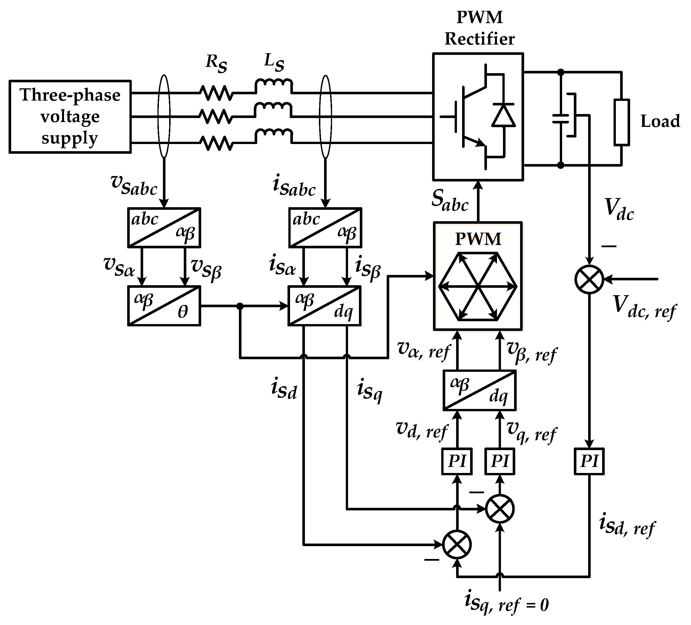
Figure 2 shows the voltage-oriented control for AC–DC line-side converters. The operation of VOC is mainly performed in the two-phase
and
domains, where Clarke and Park transformation matrices, as shown in Equations (1) and (2), respectively, are applied:
Note that
,
and
are the three-phase source voltages in
domain,
,
,
,
and
are the source voltages in the
and
domains, and
is the operating phase of the power system. A similar transformation process is applied to convert the three-phase source current
, as illustrated in
Figure 2.
By using the transformation technique, AC side control variables will become DC signals; in this manner, steady-state errors are easily eliminated by the proportional integral (PI) controllers according to the following approaches:
where
and
are the gains of the PI controller,
and
are the source current in the
domain, and
and
(derived from the measured DC voltage
of VOC rectifier) are the reference signals for
and
, respectively. After obtaining the reference voltage
and
, the inverse Park transformation, as shown in Equation (5), together with the PWM switching technique, are applied to derive the gate switching pulses
, which control the operation of the VOC rectifier. The overall domain transformation process involved in VOC operation is summarized in
Figure 3.
3. Methodology
The proposed universal charger shown in
Figure 4 is composed of a three-stage converter that is controlled by the VOC algorithm. The first stage consists of a three-phase AC source, a three-phase rectifier controlled by the VOC technique (named the VOC rectifier), and a DC-link capacitor. For closed-loop operation, the voltage and current controllers are used to obtain feedback voltage from the load-side battery of the EV. This is the most important control stage and consists of two main functions: (1) Regulating the output DC voltage to a pre-determined value, and (2) controlling the input AC phase currents to have a nearly sinusoidal wave shape and also to work in phase with the AC phase voltage.
The second stage contains an inverter controlled by the SPWM switching technique (named the SPWM inverter). The output of the PWM signal which has been filtered by the inductor–capacitor (LC) circuit, is further connected to a transformer (three-phase transformer of 50 Hz) for either step-up or step-down purposes. Note that the inverter and rectifier share the same DC-link capacitor . Generally, the inverter produces a PWM waveform, with its width varying periodically. The PWM waveform is commonly filtered by an LC filter, which generates the desired sinusoidal waveforms. A high switching frequency provides a better filtered sinusoidal waveform. The desired output voltage is generated as a result of continuous changes in the amplitude and frequency of a reference or modulating voltage. The amplitude and frequency variations of the reference voltage will change continuously. This results in pulse-width patterns of the output voltage. However, the modulation pattern will remain sinusoidal.
The modulation process is executed by comparing a low-frequency sinusoidal modulating signal with a high-frequency triangular carrier signal. Pulses with varying duty cycles are formed when the two signals intersect with each other. The intersection locations determine the switching times for each switching state of a specific variable. As illustrated in
Figure 4, three balanced-sinusoidal controlled voltages are compared with their respective triangular voltage waveforms. The resulting pulses are used to control the switching operating of the switching devices in each leg of the inverter. The switching frequency applied for the SPWM technique is set to 12 kHz. Basically, the switches in each phase are operating in a complementary manner: When the upper leg is in the open position, the lower leg will be in the closed position, and vice versa. The third stage is a three-phase diode bridge rectifier, where the control strategies of the whole charger are realized through VOC closed-loop control.
The most important part of the proposed VOC technique is the applied decoupled controller, as shown in
Figure 5. As can be observed in
Figure 5, the proposed circuit utilizes three PI controllers. The first controller is a PI voltage controller which manages the output loop of DC-link voltage
. This controller compares the measured
with its pre-determined reference value
to estimate the reference current signal
. The second controller is a PI current controller, which manages the inner loop of the
current component. This minimizes the error between
with
and then estimates the reference voltage signal
. Similarly, another PI current controller is applied to manage the inner loop of the
current component, where it reduces the
current component to 0 and, in turn, estimates the reference voltage signal
. Note that this control technique requires the three-phase AC current to be first transformed and decoupled into active
and reactive
components, respectively. The decoupled active and reactive components are then controlled in such a way that the errors between the desired reference and measured values of the active and reactive components are minimized. Generally, the active current component
is regulated by using a DC-link voltage control approach which aims to achieve an active power flow balance in the system. Meanwhile, the reactive component
is regulated to 0 to ensure unity power factor operation.
The characteristics of the PI voltage controller and the two PI current controllers are given as follows:
where
and
are the constant gain values that represent the proportional and integral gains of the PI voltage controller, respectively;
and
are the gain values for the first PI current controller;
and
are the gain values for the second PI current controllers; and
is the source inductance value. For these inner current control loops, the bandwidth
should be selected as smaller than a decade below the switching frequency (
) [
25].
where
(rad/s) is the current controller bandwidth.
For a voltage control loop, the conversational DC link capacitor is used to tune the PI controller as follows [
26,
27]:
where the damping factor
is fixed at 0.707, and
is the angular frequency. Subsequently, by using the initial value, further tuning and adjustment are performed heuristically to improve the performance of the proposed charging strategy.
4. Simulation and Experimental Setup
In this work, the simulation of the proposed EV universal charger and its control algorithms were conducted in the MATLAB/Simulink 2010a software, utilizing the SimPowerSystems toolbox. The charger circuit in the MATLAB/Simulink software is shown in
Figure 6. The main components of the circuit are capacitors, inductors, insulated-gate bipolar transistor (IGBT) switches, a three-phase transformer, and a battery as a load. The simulation parameters of the charger are listed as follows:
(1) Input Source Parameters
The circuit consists of a three phase input power supply , , and . The three-phase AC input voltage has been supplied to various values of voltage, which depend on the level of charging at a frequency of 50 Hz. The input filter consists of inductors and resistors that are connected in series, where the input inductors are 5 mH, and the input resistors are 5 Ω. The input filter has been connected to the input of the next part of the circuit (PWM rectifier).
(2) PWM VOC Rectifier
This consists of three phases: The AC source, VOC rectifier, and DC-link capacitor. For closed-loop operation, the voltage and current controllers are used to obtain feedback voltage from the load-side battery of the electric vehicles. The purposes of the control are as follows:
(3) PI Controller
This work presents three PI controllers to control three elements: , currents, and DC-link voltage. At this point, the PI controller is used for the control of the input current and output voltage. A proportional (P) controller reduces error in response to disturbances (transients) but still allows for a steady-state error. When the controller includes a term proportional to the integral of the error (I), the steady-state error will be eliminated. Dynamic response is defined as the output overshoot that occurs when the converter output load is turned on/off or abruptly changed. In this work, a PI controller for efficient operation voltage and current PI controllers were used for controlling the input current and output voltage.
(4) PWM Inverter
A PWM inverter is composed of six switches through and the output of the inverter for each phase is connected at the middle of each inverter leg. The output of the comparators provides the gating pulses required for controlling the switching operation of all three legs in the inverter. The switching frequency applied for the PWM was set at 12 kHz. Basically, the switches in each phase are operating in a complementary manner: When the upper leg is in the open position, the lower leg will be in closed position, and vice versa.
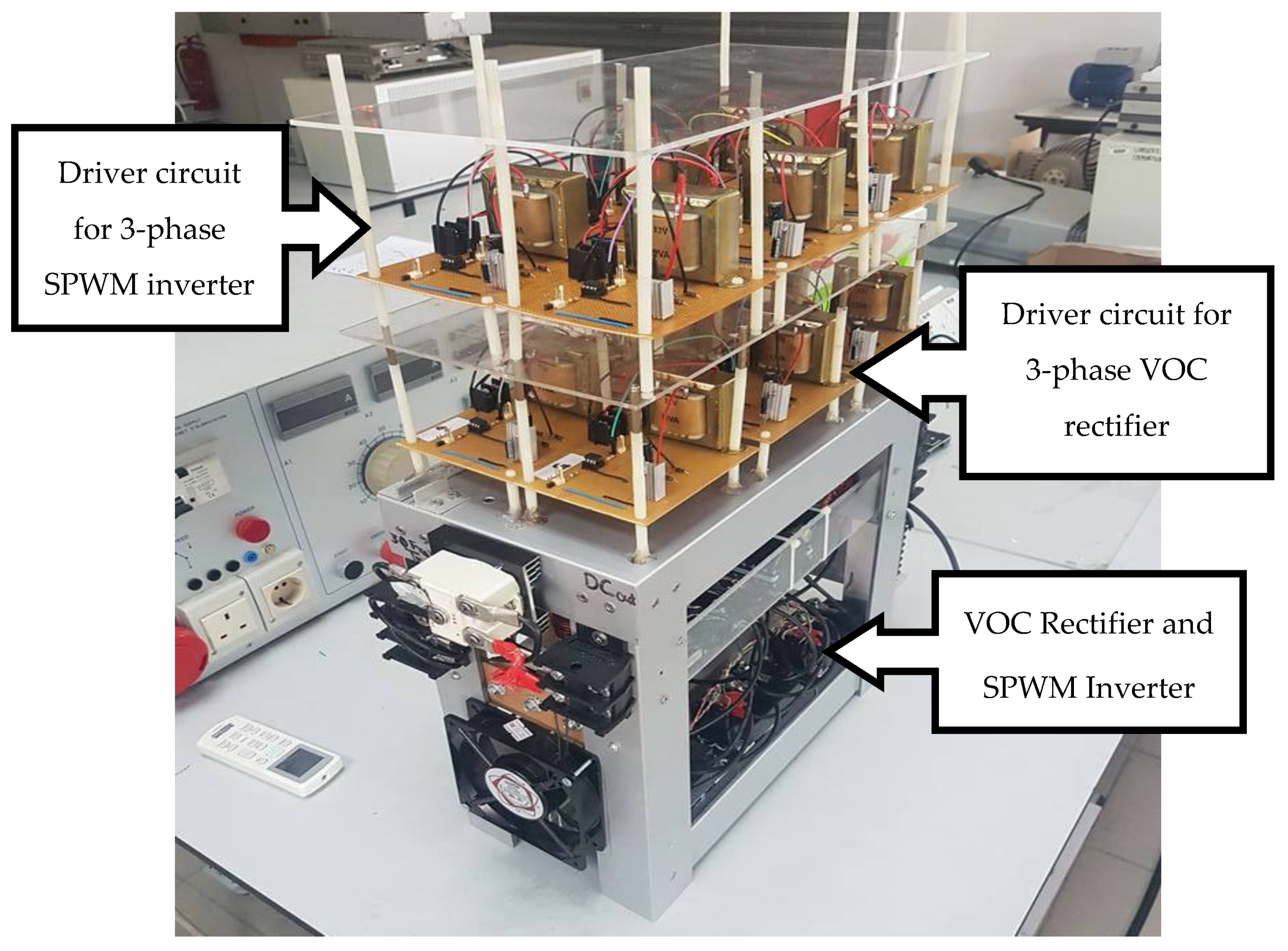
With the completion of the simulation work, the next step was developing the experimental setup to evaluate the performance of the proposed technique. A hardware prototype of the charger was built, as shown in
Figure 7. Laboratory prototypes were constructed where the controller and power electronics circuits were constructed to function as three-level chargers, similar to the one modeled in MATLAB/Simulink. The experimental set up consisted of the measurement circuit implementation, driver circuits, and a digital signal processor (DSP) board. The current and voltage sensors were developed to measure the DC current and voltage of the power supply. This research study used a current sensor of (LA-125P) and a voltage sensor of (LV-25P). All of the signals used by the VOC PWM rectifier and the SWPM inverter were processed through a DSP. The power switching device of the VOC rectifier and SPWM inverter is a module IGBT (CM200DU-24F), which needs to be isolated from a digitally based circuit or, specifically, a DSP. Thus, for this purpose, a driver circuit was designed by using an optocoupler of (LM4041C12ILP). However, in experimental work, for safety purposes and also due to resource limitations, the maximum input supply voltage for the battery charger was set to 100 Vrms (line to line). Meanwhile, the output DC reference voltage was set to 100 V. The proposed control scheme was implemented on a DSP controller (TMS320F28335), where it is can easily interface with the MATLAB/Simulink software. More importantly, the specification of this DSP model was sufficient for this work, as it provided a maximum clock frequency of 150 MHz and came with 16 ADC channels (used as input) and 12 enhanced pulse width modulator (ePWM) channels (used as output).
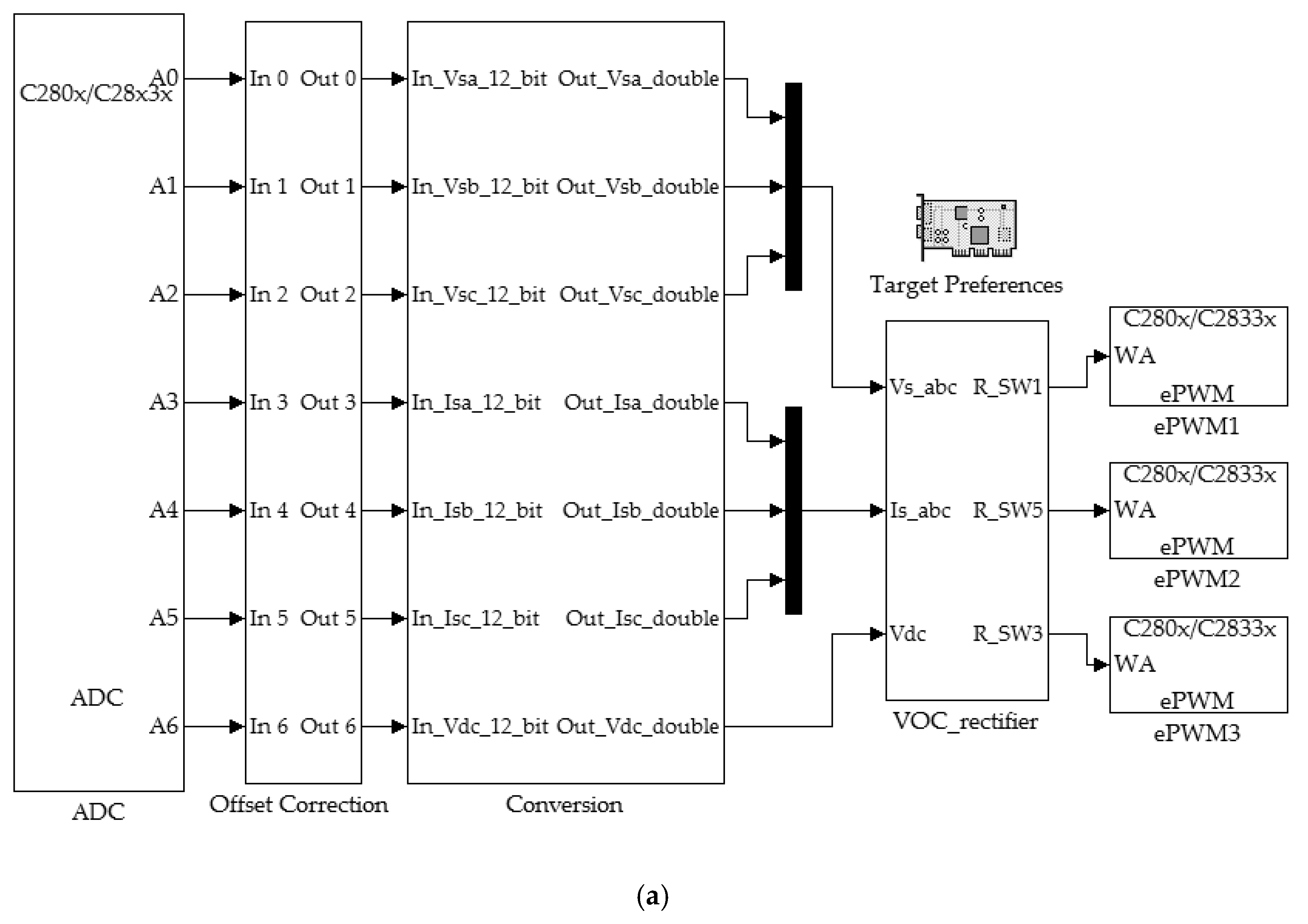
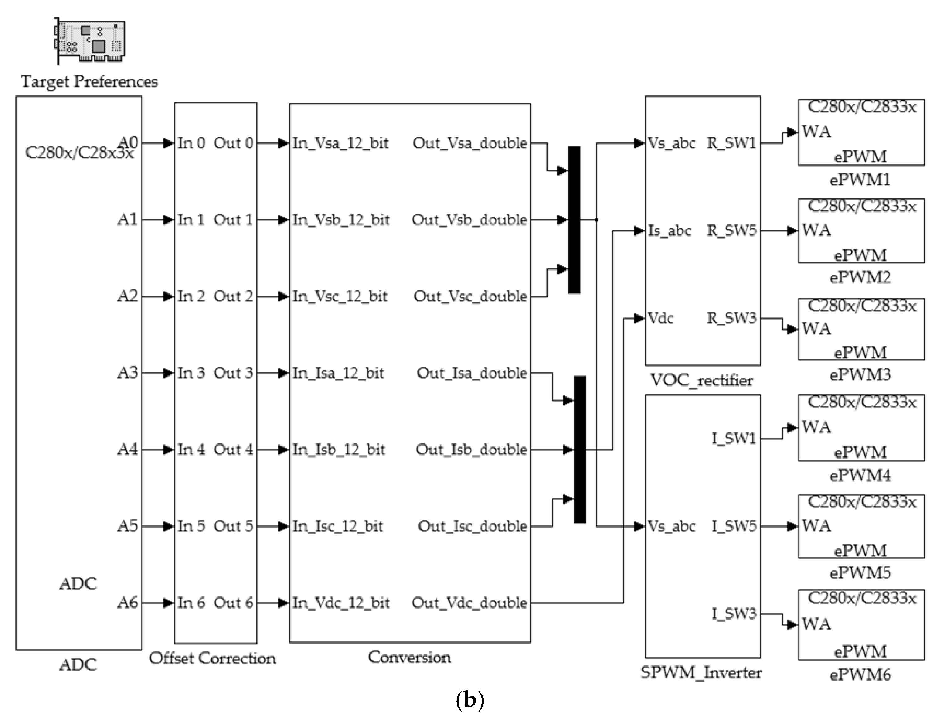
Figure 8 shows the MATLAB/Simulink model that was developed for DSP implementation. The first controller program was the ADC (Analog-to-Digital Converter) block, where the digital resolution of the converted signal was 12 bits. The output of ADC was in the range of 0–4095 because the ADC is a 12-bit converter. Finally, the ePWM block generated the ePWM. To control the switching operation of all the power converters, the control outputs of the DSP were interfaced to their respective switches via driver circuits.
7. Benchmarking
The proposed three-level universal EV charger was designed to overcome the limitations of the charging system in the previous work. The fundamental operation has been described, analyzed, and verified by simulations and experimental work in the previous sections. In this section, the features of the proposed charger are benchmarked with the capability of the few existing works.
Table 4 summarizes the performance of the proposed charger in comparison to a few existing charging systems, which include a boost converter, a non-isolation DC–DC converter, and a unidirectional charger. The comparison considers the complexity of the control structure, the THD performance, the integration of the isolation system, and the allowable level of charging standards. As summarized in
Table 4, the proposed universal charger operated by the VOC control technique provides the best advantages in terms of controller complexity and THD performance. Additionally, the integration of a three-phase transformer in the proposed charger allows for isolation between the grid and vehicle and, thus, potentially reduces the damage to the charger/vehicle due to power quality issues that occurred at the main supply. Most importantly, the proposed universal charger is able to provide all three levels of charging (Levels 1, 2 and 3), whereas the existing charger only permits single-level charging (i.e., either Level 1 or 2).
Overall, as reported by the simulation and experimental results, the design concept of the proposed universal EV charger itself and, subsequently, the operation of the VOC and SPWM algorithms in a control system, can be confirmed to be valid. The proposed universal EV charger is designed to perform three types of charging: Single-phase AC charging (Level 1), three-phase AC charging (Level 2), and DC charging (Level 3). Furthermore, the proposed VOC and SPWM control techniques are applied to minimize the harmonic distortion in the grid. As can be seen from the simulation and experimental work, the THD value is well below 5%. In other words, the proposed charging strategy does not cause significant harmonic distortions to the grid while charging.
8. Conclusions
In this research, the proposed three-level universal electric vehicle charger was successfully designed, fabricated, and tested in the lab environment. All of the objectives were successfully achieved. This research presented the design and fabrication process of a three-level universal electric vehicle charger. The proposed charger is able to provide a controllable and constant charging voltage for various EVs and is composed of three levels of charging: (1) 650 V/100 A DC for a bus or lorry, (2) three-phase 240 V/60 A AC for a saloon car, and (3) single-phase 120 V/16 A AC for a motorcycle. The three-phase PMW converter, based on the VOC of conversion theory and appropriate for Level 1, Level 2 and Level 3 of charging, was proposed. A new control algorithm based on the integration of the VOC and SPWM techniques for the effective operation of three battery charging level circuits was presented. A study was conducted that investigated the use of a three-phase converter unidirectional EV battery charger to be used in charging stations. It must be emphasized that a three-phase charger is employed for a full-bridge-based pulse-width modulation (PWM) rectifier (AC–DC) for the duration of charging. In the proposed design, the reactive and unstable active currents can be counteracted by the PWM rectifier via an inner current controller, input and output filters, and power factor correction (PFC). It is clear that the control algorithm accurately regulates the output DC voltage. At the same time, it ensures a sinusoidal input current with minimum switching ripples and distortions. The power factor of the system is almost unity, and the total harmonic distortion (THD) for the input current is less than 0.39%. However, due to limitations in terms of available facilities and resources, the ability of the proposed charging strategy in performing Level 1 and Level 2 charging have not been practically verified in this work, in which only the simulation findings have presented for this aspect. Hence, for future work, the experimental validation of Level 1 and Level 2 charging will be conducted to further support the simulation findings obtained in this work and the feasibility of the proposed charging strategy.

 ,
, 


