Article

Nonlinear Control of a Doubly Fed Generator Supplied by a Current Source Inverter

by
Krzysztof Blecharz
* and
Marcin Morawiec
Faculty of Electrical and Control Engineering, Gdańsk University of Technology, 80-233 Gdańsk, Poland
*
Author to whom correspondence should be addressed.
Energies 2019, 12(12), 2235; https://doi.org/10.3390/en12122235
Submission received: 5 April 2019 / Revised: 29 May 2019 / Accepted: 6 June 2019 / Published: 12 June 2019
(This article belongs to the Special Issue Control Strategies for Power Conversion Systems)

Abstract

:
Nowadays, wind turbines based on a doubly fed induction generator (DFIG) are a commonly used solution in the wind industry. The standard converter topology used in these systems is the voltage source inverter (VSI). The use of reverse-blocking insulated gate bipolar transistor (RB-IGBT) in the current source inverter topology (CSI), which is an alternative topology, opens new possibilities of control methods. This paper presents a novel power control system for a DFIG supplied by a CSI. The authors propose to use multi-scalar DFIG state variables. A nonlinear control method realized by feedback linearization was used to control the active and reactive powers of the generator. In the feedback linearization controls, the nonlinear DFIG model was taken into account. In the control system structure, classical proportional–integral controllers were used. The control variables were the output current vector components of the CSI. Such approach was named the “current control”. The proposed control method is characterized by good dynamic properties which, combined with the inverter properties in the rotor circuit, allow to increase the quality of the energy transferred to the grid by the generator. In the simulation tests, the correctness of the decoupling of the active and reactive power control loops, the dynamics of controlled power changes, and the change of the machine operating range resulting from the increase of the rotational speed of the generator shaft were controlled. The simulation studies also evaluated the impact of changes in the value of the passive elements of the system on the operation of the generator system. Characteristic operating states of the generator system were analyzed using computer simulations.

1. Introduction

Doubly fed induction generator (DFIG) systems are widely used in wind power plants. The configuration of these systems is based on the use of a voltage source inverter. In a classic configuration of a generator system, the stator of a doubly fed generator is connected to the main grid, while the rotor is supplied by a voltage source inverter (VSI). An alternative but rarely used solution is to use a current source inverter (CSI) to supply the rotor side of the generator. Power electronics constructions with a CSI were popular in the 1980s. In this configuration, circuits with thyristors were used as power switches [1]. Because of their numerous disadvantages, such as a complicated auxiliary supply thyristor system and long switching times, these solutions have been replaced in the market by VSIs with insulated gate bipolar transistors transistors. In the last years, the dynamic development of semiconductor devices has led to the appearance on the market of IGBT transistors with serially connected diodes, which were called reverse-blocking transistors (RB-IGBT) [2,3]. These new semiconductor switches have opened new possibilities for the design and construction of power electronics circuits, CSIs in particular. This fact motivated the authors to look for solutions in the field of DFIG control with CSIs. Another reason for investigating this field is the lack of papers describing such solutions in the literature. The literature on the issues of a DFIG powered by a CSI is scarce [4,5,6,7]. The fundamental properties of a DFIG supplied by a CSI with regard to operating ranges and power flow were presented in some studies [4,5]. In [4], the author showed a theoretical analysis of the properties of a DFIG system supplied by a controlled current source in the rotor circuit. These results were confirmed in another study [5], in which the cyclo-converter in the rotor power supply system was replaced by a CSI. In both cases, good dynamic properties of this types of system were shown. The authors of [6] proposed the use of a control structure without a rotor speed sensor in the system with the CSI. The proposed solution highlighted some difficulties in using the sensorless control algorithm due to the use of thyristors as switching elements. The possibility to use the multi-scalar nonlinear control of a DFIG was first presented in [7]. However, the described solution used hysteresis current control of the voltage inverter, whose basic disadvantage is the variable frequency of switching power devices.
Most of the available publications concern drive systems with a cage motor supplied by a CSI [8,9,10,11,12]. All authors confirm the high dynamics of the presented CSI systems, emphasizing, however, the hardware difficulties associated with the use of thyristor switches [8,9] and high harmonic content in the output current due to the low-frequency switching of the thyristor [10,11]. A very interesting comparison of the two current inverter structures in the thyristor front-end rectifier and pulse width modulation (PWM) front-end rectifier configuration is shown in [12]. Another area where the application of CSI can be found is permanent magnet synchronous generator control [13,14]. In [13], the authors showed a novel power control system with a CSI inverter based on the field-oriented control (FOC) method. A similar structure of the system is shown in [14]. In both articles, the authors draw attention to the benefits of eliminating the capacitors in the DC link circuit and the general improvement of the reliability of the entire system, with a reduction of losses in the inverter and the high quality of the power transmitted to the network.
Regardless of how the rotor of the DFIG is supplied, the active and reactive powers transferred to the grid can be controlled by various methods. The classic approach to active and reactive power control of a DFIG is the FOC [15,16], which can be applied with some variations. Another approach is the direct power control (DPC) [17,18] based on the direct torque control (DTC) method from induction motor control systems. In [19], a different kind of power control systems based on a nonlinear control method was shown. This paper proposes a novel power control system for DFIGs where the rotor is supplied by a CSI. For control system synthesis, a less popular variation of the input–output nonlinear control method based on multi-scalar Z-type variables was used. The performance and utility of the proposed solution were verified in several simulations.

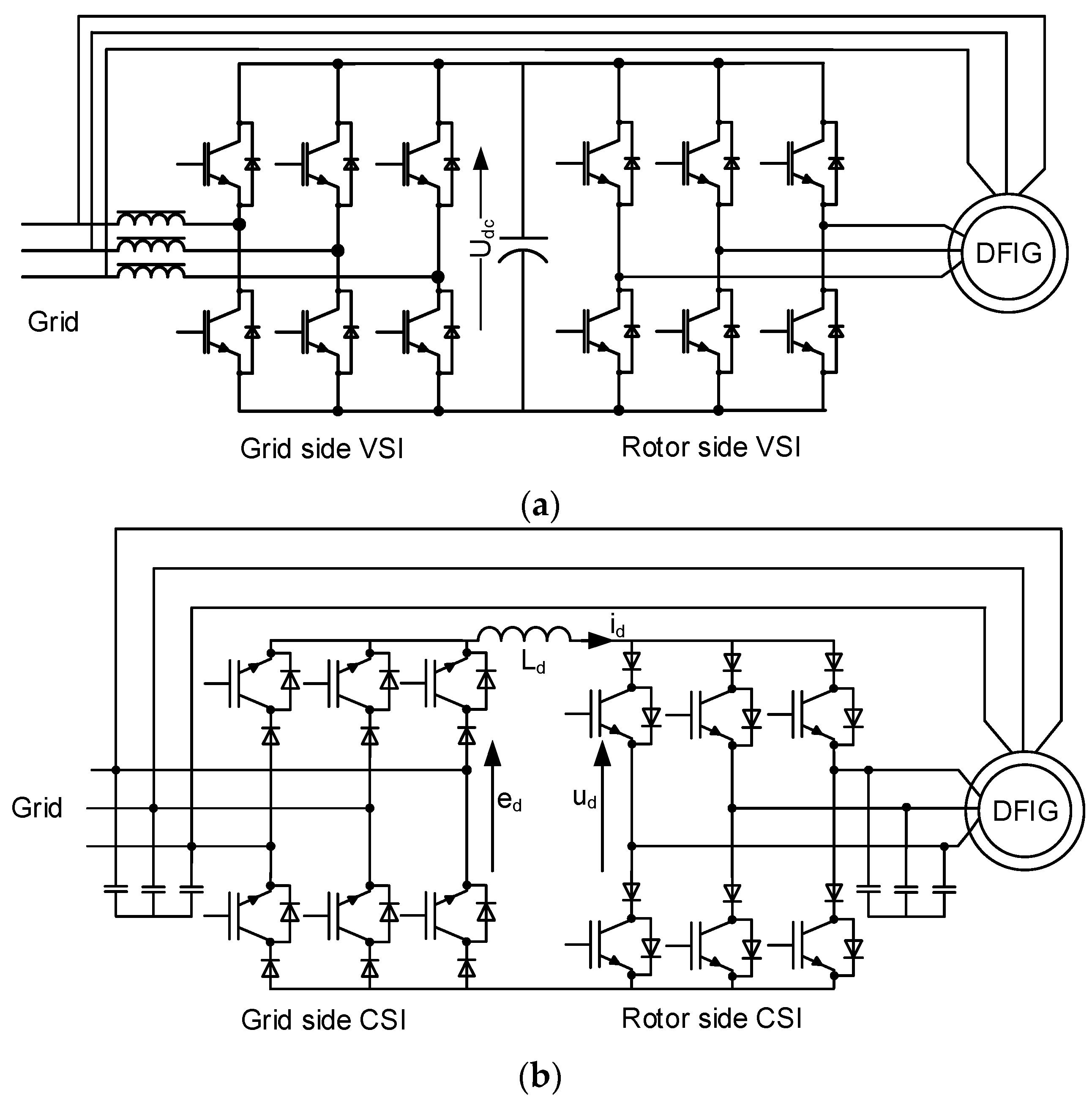
2. Doubly Fed Generator System

A typical VSI supply system with a DFIG is shown in Figure 1a. In this configuration, the rotor of the generator is supplied by voltage rectangular pulses generated by the inverter according to a PWM algorithm. The shapes of the rotor current depend on the adopted PWM method and the parameters of the circuit. The choice and correct application of the PWM method does not guarantee the attainment of rotor currents without any distortions. The cable connection between the buck-to-buck converter and the generator must be shielded to limit electromagnetic interference. The length of the cable is also limited by wave effects.
The supply of the generator rotor by a CSI reduces or completely eliminates the described problems. A standard topology of current source converter (CSC) supply of a DFIG with PWM front-end rectifiers is shown in Figure 1b. The principle of operation of this solution is to maintain a constant direct current value in the DC link circuit of the converter using the grid side of the converter. The rotor side of the converter functions as an electronic commutator to generate a current impulse in accordance with the PWM current algorithm. For a correct operation of the system, a capacitor bank connected to the rotor circuit is used as a filter. The generator system with a CSC consists of a few basic components or devices: two power stages of the CSI with RB-IGBT or different kinds of power electronic switches, two passive filters with capacitors, and a DC link circuit with main inductance Ld.
DFIG systems with a CSI are characterized by a few positive features in relation to the systems with a VSI. The cable length between the converter and the generator does not have a large effect on the operation of the whole supply system. The occurrence of a short circuit on the generator rotor is not dangerous because it is a natural operating state of the inverter. In the design of the CSI, it is not necessary to use low-inductance connections between converter switches modules to limit overvoltage on the transistors during fast switching. These properties simplify the design of the converter considerably. The main drawbacks of CSI systems include the sensitivity to a sudden current interruption in the load circuit, resulting in the induction of a high voltage and system damage. The inductor in the DC link circuit, which is an energy storage element, especially in high-power systems, is expensive, and its dimensions can be considerable.

3. Generator Model

3.1. Vector Model of the Machine

The dynamics of the DFIG in a vector form set of equations are represented in any reference frame rotating at ωa as [19]:
d Ψ s x d τ = R S L S Ψ s x + R S L m L S i r x + ω a Ψ s y + u s x
d Ψ s y d τ = R S L S Ψ s y + R S L m L S i r y ω a Ψ s x + u s y
d i r x d τ = L S 2 R r + L m 2 R S L S w σ i r x + R S L m L S w σ Ψ s x + ( ω a ω r ) i r y L m w σ ω r Ψ s y + L s w σ u r x L m w σ u s x
d i r y d τ = L S 2 R r + L m 2 R S L S w σ i r y + R S L m L S w σ Ψ s y + ( ω a ω r ) i r x L m w σ ω r Ψ s x + L s w σ u r y L m w σ u s y
d ω r d τ = L m J L S ( Ψ s x i r y Ψ s y i r x ) 1 J T d r
where Rs and Rr are the resistances of stator and rotor windings, Ls, Lr are the inductances of stator and rotor windings, Lm is a mutual inductance between the generator windings. The symbols J and Tdr indicate the moment of inertia and the drive torque of the machine, respectively.

3.2. Multiscalar Z-Type Model of the Machine

The dynamics of the DFIG can be written in a different mathematical form. It is necessary to adopt new nonlinear variables to derive the system of equations. The nonlinear variables, named Z-type multi-scalar, are defined differently as follow [19]:
z 11 = ω r
z 12 = Ψ s x i r y Ψ s y i r x
z 21 = Ψ S 2
z 22 = Ψ s x i r x + Ψ s y i r y
Determining the derivatives of such adopted variables, taking into account Equations (1)–(5) of the mathematical model, leads to a new system of equations:
d z 11 d τ = L m J L S z 12 1 J m 0
d z 12 d τ = 1 T V z 12 + z 11 z 22 + L m w σ z 11 z 21 + L s w σ u r 1 L m w σ u s f 1 + u s i 1
d z 21 d τ = 2 R S L S z 21 + 2 R S L m L S z 22 + 2 u s f 2
d z 22 d τ = 1 T V z 22 + R S L m L S w σ z 21 + R S L m L S z 12 2 + z 22 2 z 21 z 11 z 12 + L S w σ u r 2 L m w σ u s f 2 + u s i 2
where
u r 1 = u r y Ψ s x u r x Ψ s y u r 2 = u r x Ψ s x + u r y Ψ s y
u s i 1 = u s y i r x u s x i r y u s i 2 = u s x i r x + u s y i r y
u s f 1 = u s y Ψ s x u s x Ψ s y u s f 2 = u s x Ψ s x + u s y Ψ s y
Such a transformation of the system in Equations (10)–(13) leads to a reduction in the order of the DFIG model. By writing the model equations in this form, the Z-type multi-scalar variables are independent from the selected coordinate system and only depend on the length of selected vectors and the angle between them.
The application of the feedback in the form
u s i 1 = m 1 z 11 z 22 L m w σ z 11 z 21 L m L S w σ z 21 L S w σ u r 1 + L m w σ u s f 1
u s i 2 = m 2 R S L m L S w σ z 21 R S L m L S z 12 2 + z 22 2 z 21 + z 11 z 12 L S w σ u r 2 + L m w σ u s f 2
results in two decoupled second-order linear systems. Two subsystems can be distinguished in this system. The first mechanical subsystem is
d z 11 d τ = L m J L S z 12 1 J T d r
d z 12 d τ = 1 T V ( z 12 + m 1 ) ,
and the second electromagnetic subsystem is
d z 21 d τ = 2 R S L S z 21 + 2 R S L m L S z 22 + 2 u s f 2
d z 22 d τ = 1 T V ( z 22 + m 2 )
where Tv is a combination of generator parameters and defines the electromagnetic time constant of a machine, and m1 and m2 are the new control signals.
It is possible to create a different form of the mathematical generator model by selecting another variant pair of vectors from a set of machine state variables, for example by combining pairs, such as (Ψr, is) or (Ψm, ir), etc. The difficulty in each case, if it exists, is to find decoupling equations of the model and mathematical formulas for active and reactive powers expressed with the use of nonlinear variables.

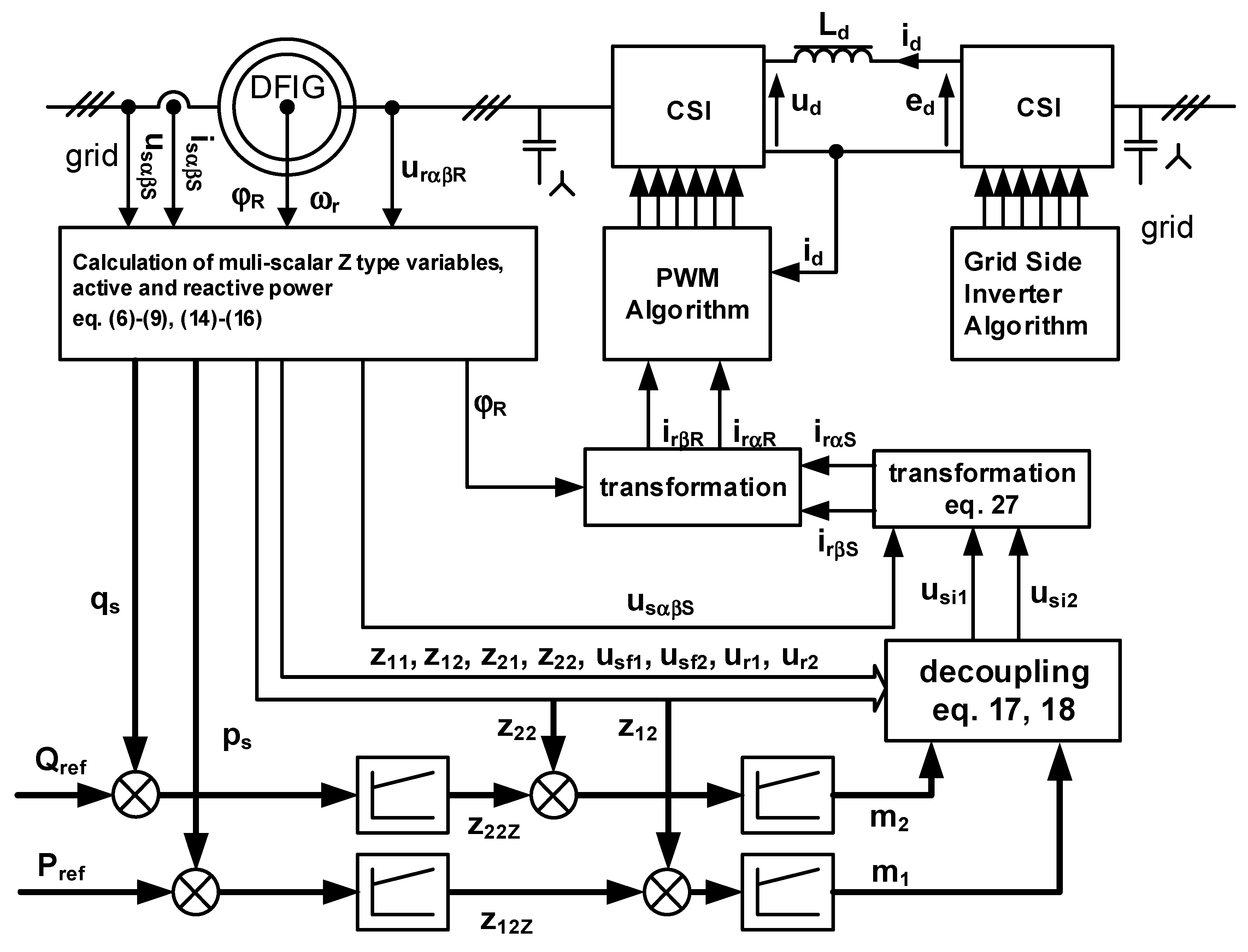
4. Active and Reactive Power Control System

The power control system of a DFIG should provide decoupled control of active and reactive powers. Active sp and reactive sq powers using Z-type multi-scalar variables (6)–(9) can be expressed in a per-unit (p.u.) system in the form:
s p = 1 L s u s f 2 L m L s u s f 1 z 12 + u s f 2 z 22 z 21
s q = 1 L s u s f 1 L m L s u s f 1 z 22 u s f 2 z 12 z 21
It should be noted that Equations (23) and (24) may be simplified due to the fact that in steady-state, the auxiliary variables usf1 and usf2 are approximately equal to 1 and 0 in p.u. In the simplified version of the equations, they take the form:
s p = L m L S z 12
s q = 1 L S L m L S z 22
The components of the rotor current in a stationary reference frame can be calculated from the values of the usi1 and usi2 variables by the expression:
i r α S = u s i 1 u s β S + u s i 2 u s α S u s 2 i r β S = u s i 2 u s β S u s i 1 u s α S u s 2
In this way, the determined components of the rotor current after transformation (Equation (32)) to a stationary rotor reference frame, using the rotor position angle φr, are the reference values for the PWM algorithm.
Figure 2 presents a schematic diagram of the nonlinear control strategy. The control system has four proportional–integral controllers (PI) controllers in two independent power control loops. The inner control loops are responsible for the control of the multi-scalar variables z12 and z22. The outer loops allow for active and reactive power control and set the reference values for the inner PI controllers. The gains of all PI controllers are shown in Table A2 in Appendix A. This cascade control system approach is used most commonly.

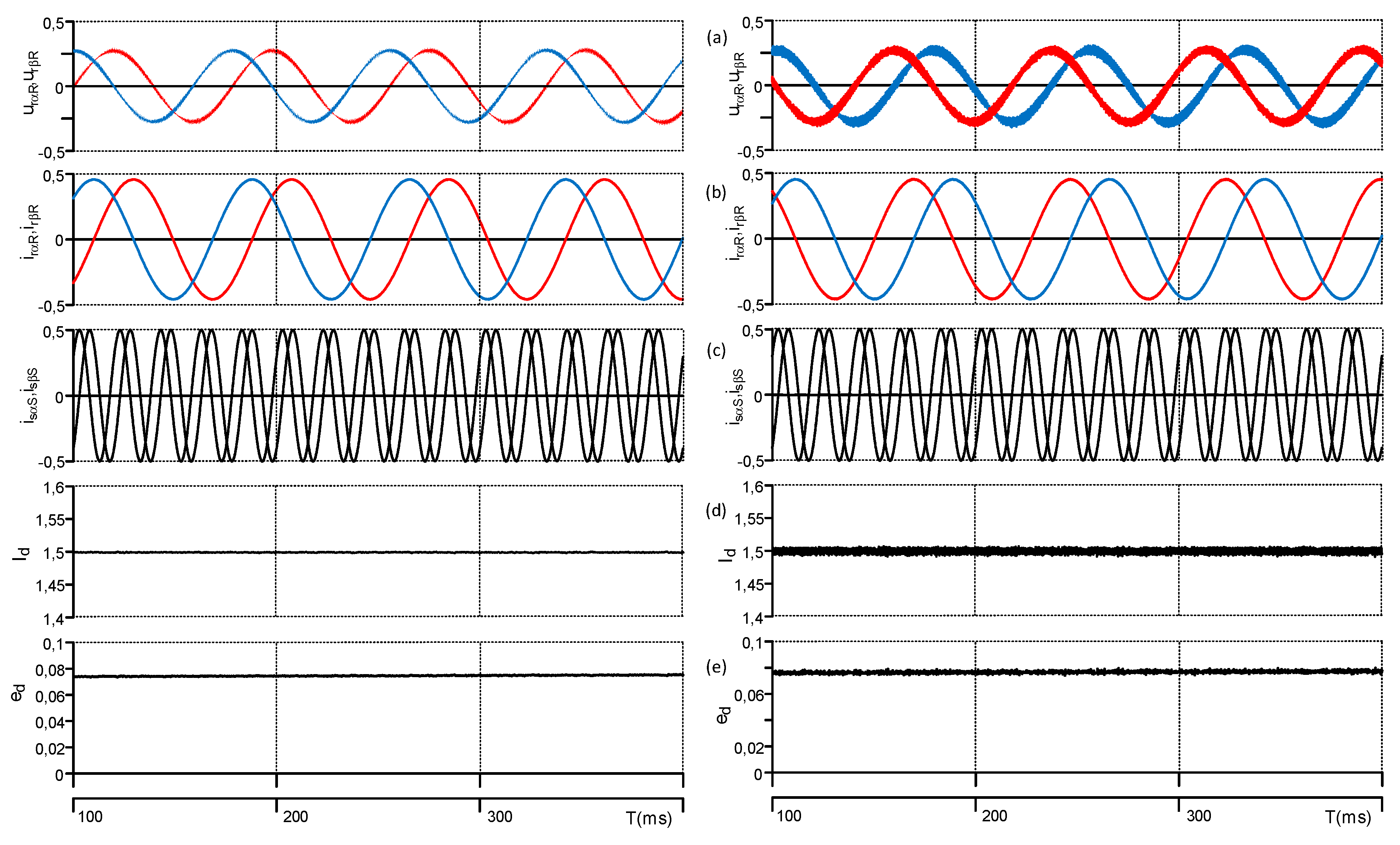
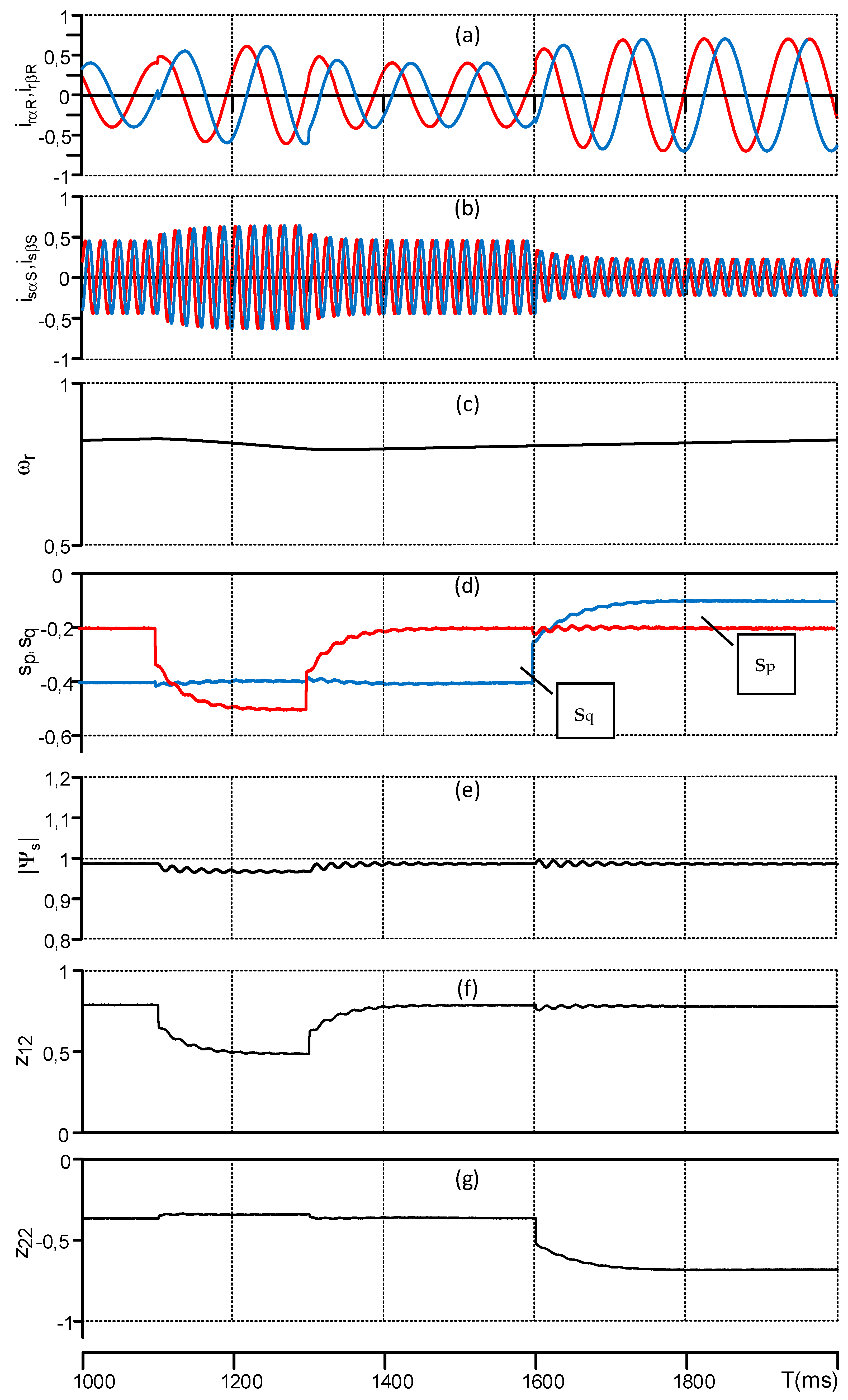
5. Model and Simulation Results

This section presents the model description and simulation results in order to illustrate the behavior of the proposed active and reactive power control system of a DFIG supplied by a CSI. The model of the analyzed supply system with a CSI is shown in Figure 3.
The system model is divided into a few parts. The grid side inverter operation was not directly included in the simulation program. This part of the simulation system was replaced by an adjustable voltage source. One of the control strategies of the DFIG supplied by a CSI was based on a forced constant value of the current in the DC link. The current source inverter worked in various modulation indexes (defined as the ratio of the rotor current module to the value of the DC-link current). The reference current idref was then treated as the input of the PI controller and compared to the measured value of the DC-link current. The voltage obtained from the PI controlled output is marked as ed, and its value not only is constant but also depends on the DFIG working points. The dynamics of the current id in a direct current link circuit is expressed as:
d i d d t = R d L d i d + 1 L d ( e d u d )
The value of direct voltage ud is
u d = i r α R u r α R + i r β R u r β R I d
For a correct operation of the system, an output filter connected directly to the current inverter terminals is required. The voltage on the output filter Cm changes the value according to:
d u c d t = 1 C m ( i f i r )
Taking into account the dynamics of voltage uc changes on the passive filter, the rotor voltage at the terminals of the generator rotor is defined as
u r = R c ( i f i r ) + u c
where all vector quantities are in bold.
It was assumed that the power stage of the rotor side CSI was an ideal lossless energy conversion system. The main purpose of the rotor side CSI was to form a sinusoidal output rotor current. In the simulation program, the space vector pulse width modulation (SV-PWM) method described in [20] was used. In this method, six active vectors and three passive vectors are used. A typical sequence of space vectors is passive–active–active. The passive vector denotes a state where two transistors are switched on in the same branch of power stage in a current inverter. It is a natural operating state of the current inverter and it is not dangerous for the converter. The transition between consecutive sequences of space vectors must take place during an uninterrupted flow of DC current, therefore it is necessary to keep the overlap time short. If this does not occur, the lack of a continuous current leads to high-voltage spikes on the DC-side inductor, which may damage the transistors. In the simulation, an overlap time value equal to zero was assumed. A detailed analysis of the influence of the overlap time effect on the operation of the SV-PWM current source inverter has been presented [21].
The sequence of SV-PWM has a large influence on common-mode voltage reduction and may cause bearing currents, especially in high-power machines, as described in [22]. Another interesting aspect of the construction of CSI, shown in [23], is the use of silicon carbide transistors, which allow to increase the frequency of the PWM modulator to tens of kHz and reduce the size of passive elements in the inverter.
In order to analyze the operation of the proposed power control system simulation, studies were performed. The simulation tests included checking the correctness of the decoupling of the active and reactive power control loops, the dynamics of controlled power changes, and the change of the machine operating range resulting from the increase of the rotational speed of the generator shaft.
The simulation studies also evaluated the impact of changes in the value of the passive elements Ld and Cm of the system on the operation of the generator system.
All simulation results were obtained using a simulation program written in C++ programming language by the research team. Open and free software was used to write the simulation program. The classical Runge–Kutta method with 1 μs integration step was used to integrate the differential equations of the generator system. The simulation program contained the DFIG model according to Equations (1)–(5), the functional CSI model with the output filter (28)–(31), and all structures of a control system. The discrete nature of the control system and of the power converter was taken into account. A control system impulse period of 150 μs was assumed. In the simulation, according to the real machine, the parameters of a 2 kW wound-rotor induction machine were considered. All values obtained on the basis of the simulation studies were expressed in per units.
The parameters of the simulation model and the reference units are shown in Table A1 (Appendix A). The position and rotor speed of the generator were known.
The following description method of vector reference frame was adopted on all presented simulation results. The model vector components in a stationary rotor reference frame have indexes αR and βR, while the vector components in stationary stator reference frame have indexes αS and βS.
The following scenarios were investigated in the simulations:
(1)
Changes of the CSI parameters influencing the stator and rotor current and voltages—Figure 4 and Figure 5;
(2)
Changes of the reference active and reactive powers—Figure 6;
(3)
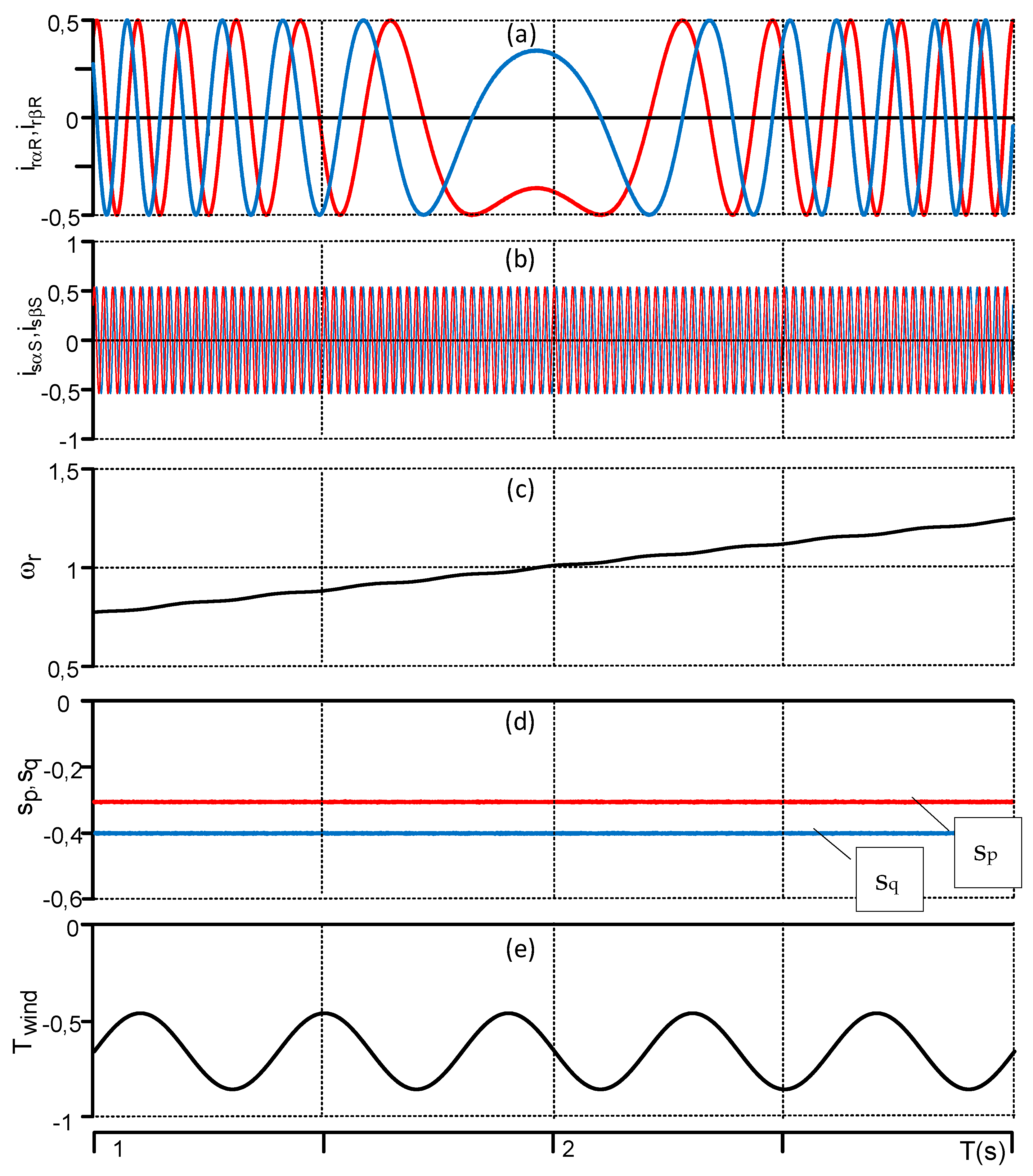
DFIG system behavior during changes of the rotor speed from under-synchronous to over-synchronous speed with constant reference active and reactive powers—Figure 7.
(4)
DFIG system behavior during changes of the active and reactive powers with constant driven torque—Figure 8.
In the above investigations, all the changes of the reference reactive and active powers were limited to the nominal value of stator and rotor current. Typical tests are performed with a DFIG connected to the grid while controlling the active and reactive powers by an inverter on the rotor side.
Figure 4 shows characteristic transient waveforms for the simulation model in steady state for different values of Lm main choke inductance, i.e., urαR, urβR, rotor voltage vector components, irαR, irβR, rotor current vector components, isαS, isβS, stator current vector components, Id, current in the DC link circuit, ed, controlled voltage source. Changing the main inductance value from 0.05 p.u. to 0.02 p.u. resulted in the appearance of high-frequency oscillations in direct current in the DC link circuit. It caused the deterioration of the working conditions of the PWM algorithm and worsened the operating conditions of the entire power supply system.
Figure 5 shows two causes of characteristic transient waveforms for the simulation model in a steady state for different values of Cm passive output filter capacitance, i.e., ifαR, current inverter output vector component, icαR, current filter vector component, irαR, rotor current vector component, isαS, stator current vector component, ud, voltage in the DC link circuit, urαR, rotor voltage vector component. For the sake of clarity, only the component α of the vectors is shown in Figure 5.
The incorrect selection of the capacitance (0.1 p.u.) caused distortions of high harmonics in the rotor and stator currents waveforms. The rotor current was very smooth without any additional high harmonics when the capacitance assumed the proper value of 0.35 p.u.
For the purpose of the simulation studies, the harmonic content (THDi) was assumed in the output current at the level of 1%, and for this value, the parameters of the passive elements (Rc, Cm, Ld) were selected.
The inductance value of the DC choke Ld can be calculated from Equation (32):
L d = 1 Δ i d t 1 t 2 ( e d u d ) d t
where Δid is the allowed current oscillation in the DC-link circuit, and t1, t2 are times resulting from the switching frequency of PWM.
In summary, the correct selection of the inductance value of the inductor in the circuit and of the capacitance value of the filtering condenser ensures the correct operation of the system. The current and the voltage supplying the generator rotor circuit did not contain higher harmonics. This translated into a higher quality of energy transferred to the system.
Figure 6 presents the reaction of the power control system for two reference power changes. In Figure 6, after 100 ms, the reference active power changed from −0.2 to −0.5 p.u. and next, after 600 ms, the reactive power changed from −0.4 to −0.1 p.u. (lagging). While changing the reactive power, the rotor current increased as a result of a build-up of the magnetising current component at the rotor side of the generator. Thus, the stator current decreased. The stator active and reactive power oscillations were smaller than 2% of the reference values and resulted from the natural character of the generator. The decoupling of the active and reactive power control loops was proper. In this scenario, the reference active and reactive powers were changed so to obtain the real DFIG working conditions.
Next, the behaviour of the DFIG system was tested while changing the rotor speed from under to over-synchronous. Figure 7 presents the following waveforms: irαR, irβR, rotor current vector components and isαS, isβS, stator current vector components, after the ωr rotor speed has increased from 0.7 p.u. to 1.3 p.u. as a consequence of an increased mean value of the drive torque Tdrive. The regulated values of active sp and reactive sq powers were maintained at the set values of sp = −0.35 and sq = −0.4 (lagging) in the entire range of the rotational speeds tested, despite the oscillating nature of the driving torque. The waveforms presented in Figure 7 confirmed that the control system structure with the proposed multi-scalar transformation and feedback control law, which is based on the DFIG model, was stable.
Figure 8 presents the reaction of the power control system for three changes of the reference active power and one change of the reference reactive power. It was assumed that the drive torque on the generator shaft was constant. This case corresponds to a constant wind speed, which occurs within the assumed 5 s time interval. In Figure 8, after 1 s, the reference active power changed from −0.2 to −0.5 p.u. after every 1 s, then after 4 s, the reactive power changed from −0.4 to 0. The power coefficient at the generator output changed in this case from 0.41 to 1. The reactive power necessary to magnetize the generator was generated on the rotor side, therefore, the value of the rotor currents in 5 s was increased. Also, in the shown case, decoupling between active and reactive power control loops occurred, as shown in Figure 8. The power control algorithm worked correctly.

6. Conclusions

This study proposes a novel power control system for a DFIG where the rotor is supplied by a CSI. For control system synthesis, a not widely known variation of the input–output nonlinear control method based on multi-scalar Z-type variables was used. The performance and utility of the proposed solution were verified by simulations. All simulation tests confirmed the correctness of the proposed power control system concept. The presented system is characterized by high dynamics of operation with independent ability to control the active and reactive powers of the generator. The advantage of the presented solution is represented by the sinusoidal currents in the rotor circuit which translate into high power quality with a reduced harmonics content in the stator currents. The control structure presented in this paper with a multi-scalar transformation confirmed that the DFIG system is stable in the three proposed scenarios. In the case of the CSI structure, it is important to determine the filter capacitor and in the DC-link inductor values. These values influence the control system stability, as shown in the first scenario. The theoretical analysis presented in this paper allows to use the proposed control system structure for practical verifications. This will be presented in future works.

Author Contributions

Conceptualization, K.B.; software, K.B.; validation, K.B.; investigation, K.B.; writing—original draft preparation, K.B.; writing—review and editing, K.B., M.M.; visualization, K.B.; All authors carried out the theoretical analysis and contributed to writing the paper.

Funding

This research received no external funding.

Conflicts of Interest

The authors declare no conflict of interest.

Nomenclature

Rs, Rrstator and rotor resistances;
Ls, Lrstator and rotor inductances;
Lmmutual inductance;
Jmoment of rotor inertia;
Tdrdrive torque;
ωr, z11pulsation of reference frame;
ωamechanical speed;
sp, sqstator active and reactive powers;
z12, z22, z21Z-type multi-scalar variables;
ur1, ur2, usi1, usi2Z-type auxiliary multi-scalar variables;
m1, m2control variables;
idDC-link current;
ed, udDC-link voltages;
Rd, LdResistance and inductance of DC-link choke;
Cmoutput filter capacitance.

Appendix A

Table A1. Generator parameters and reference unit.
SymbolQuantityValues
Rsstator resistance2.833 Ω/0.067 p.u.
Rrrotor resistance 2.867 Ω/0.068 p.u.
Lmmagnetizing inductance0.15 H/1.123 p.u.
Ls, Lrstator and rotor inductance0.164 H/1.1227 p.u
Lσleakage inductance0.014 H/
Pnnominal power2 kW
Insnominal stator current5.5 A
Inrnominal rotor current3.4 A
Unnominal stator voltage400 V
nnominal rotor speed 910 rpm
fnominal frequency50 Hz
rturn ratio Ns/Nr1
Ldchoke inductance6.2 mH/0.05 p.u
Cmfilter capacitance280 uF/0.35 p.u
Ub = Unreference voltage400 V
I b = 3 Insreference current9.52 A
Sbreference power3810 VA
Table A2. Parameters of PI regulators in reference units.
SymbolQuantityValues
kpPproportional gain for active power controller1.5
kiPintegral gain for active power controller0.15
kpQproportional gain for reactive power controller1.5
kiQintegral gain for reactive power controller0.15
kp12proportional gain for z12 variable controller2.5
ki12integral gain for z12 variable controller0.5
kp22proportional gain for z22 variable controller2.5
ki22integral gain for z22 variable controller0.5
The transformation from the stator reference frame to the rotor reference frame is defined as follows:
[ i r α R i r β R ] = [ cos ( φ r ) sin ( φ r ) sin ( φ r ) cos ( φ r ) ] [ i r α S i r β S ]

References

  1. Hombu, M.; Ueda, S.; Ueda, A.; Matsuda, Y. A New Current Source GTO Inverter with Sinusoidal Output Voltage and Current. IEEE Trans. Ind. Appl. 1985, 5, 1192–1198. [Google Scholar] [CrossRef]
  2. Vellvehi, M.; Galvez, J.L.; Perpina, X.; Jorda, X.; Godignon, P.; Millan, J. Trench isolation technique for Reverse Blocking IGBT using Boron Nitride doping wafers. In Proceedings of the 13th European Conference on Power Electronics and Applications (EPE 2009), Barcelona, Spain, 8–10 September 2009. [Google Scholar]
  3. Takei, M.; Harada, Y.; Ueno, K. 600V-IGBT with reverse blocking capability. In Proceedings of the 13th International Symposium on Power Semiconductor Devices and ICs (ISPSD’01), Osaka, Japan, 4–7 June 2001. [Google Scholar] [CrossRef]
  4. Walczyna, A. Właściwości maszyny indukcyjnej dwustronnie zasilanej sterowanej źródłem prądu w obwodzie wirnika (polish) (A properties of a double-fed induction machine controlled by a current source in the rotor circuit). Prz. Elektrotech. Zesz. 1982, 10, 70–75. [Google Scholar]
  5. Smith, G.A.; Nigim, K.A. Wind-energy recovery by a static Scherbius induction generator. IEE Proc. C-Gener. Transm. Distrib. 1981, 128, 317–324. [Google Scholar] [CrossRef]
  6. Lefley, P.W.; Peasgood, W.; Ong, R.; Wong, J.K.J. Sensorless closed loop control of a slip ring induction machine using adaptive signal processing. In Proceedings of the APEC 99, Fourteenth Annual Applied Power Electronics Conference and Exposition 1999 Conference Proceedings (Cat. No.99CH36285), Dallas, TX, USA, 14 March 1999; Volume 2, pp. 1251–1256. [Google Scholar] [CrossRef]
  7. Bogalecka, E.; Krzeminski, Z. Control systems of doubly-fed induction machine supplied by current controlled voltage source inverter. In Proceedings of the 1993 Sixth International Conference on Electrical Machines and Drives (Conf. Publ. No. 376), Oxford, UK, 8–10 September 1993; pp. 168–172. [Google Scholar]
  8. Mark, A.P.; Irudayaraj, G.C.R.; Vairamani, R.; Mylsamy, K. Dynamic Performance Analysis for Different Vector-Controlled CSI-Fed Induction Motor Drives. J. Power Electron. 2014, 14, 989–999. [Google Scholar] [CrossRef]
  9. Dakir, A.; Nowak, M.; Grochal, P.; Barlik, R. Simulation of a AC-drive with PWM current inverter and induction machine. In Proceedings of the 1995 Proceedings IEEE International Symposium Industrial Electronics, Dubrovnik, Croatia, 10–14 July 1995; Volume 1, pp. 327–331. [Google Scholar] [CrossRef]
  10. Kolmakov, N.M.; Bakhovtsev, I.A. Three-phase current source inverter with hysteresis control in voltage source mode. In Proceedings of the 16th International Conference of Young Specialists on Micro/Nanotechnologies and Electron Devices, Erlagol, Altai, 29 June–3 July 2015; pp. 429–432. [Google Scholar] [CrossRef]
  11. Wu, B.; Dewan, S.B.; Slemon, G.R. PWM-CSI inverter for induction motor drives. In Proceedings of the Conference Record of the IEEE Industry Applications Society Annual Meeting, San Diego, CA, USA, 1–5 Octorber 1989; Volume 1, pp. 508–513. [Google Scholar] [CrossRef]
  12. Espinoza, J.R.; Joos, G. A current-source-inverter-fed induction motor drive system with reduced losses. IEEE Trans. Ind. Appl. 1998, 34, 796–805. [Google Scholar] [CrossRef]
  13. Dai, J.; Xu, D.; Wu, B. A Novel Control Scheme for Current-Source-Converter-Based PMSG Wind Energy Conversion Systems. IEEE Trans. Power Electron. 2009, 24, 963–972. [Google Scholar] [CrossRef]
  14. Singh, A.; Benzaquen, J.; Mirafzal, B. Current Source Generator–Converter Topology for Direct-Drive Wind Turbines. IEEE Trans. Ind. Appl. 2017, 54, 1663–1670. [Google Scholar] [CrossRef]
  15. Chwa, D.; Lee, K.B. Variable Structure Control of the Active and Reactive Powers for a DFIG in Wind Turbines. IEEE Trans. Ind. Appl. 2010, 46, 2545–2555. [Google Scholar] [CrossRef]
  16. Yang, S.; Ajjarapu, V. A Speed-Adaptive Reduced-Order Observer for Sensorless Vector Control of Doubly Fed Induction. Energy 2010, 25, 891–900. [Google Scholar]
  17. Pura, P.; Iwanski, G. Direct Torque Control of a Doubly-Fed Induction Generator Connected to Unbalanced Grid. Prz. Elektrotech. 2016, 1, 42–46. [Google Scholar] [CrossRef] [Green Version]
  18. Kalamian, N.; Kazemi, M.V.; Gholomian, S.A. Direct power control of DFIG by using nonlinear model predictive controller. Asian J. Control 2016, 18, 985–999. [Google Scholar] [CrossRef]
  19. Krzeminski, Z. Sensorless multiscalar control of double fed machine for wind power generators. In Proceedings of the Power Conversion Conference-Osaka 2002, Osaka, Japan, 2–5 April 2002; Volume 1, pp. 334–339. [Google Scholar] [CrossRef]
  20. Morawiec, M.; Krzeminski, Z.; Wlas, M. PWM current source inverter with IGBT transistors and multiscalar model control system. In Proceedings of the 2005 European Conference on Power Electronics and Applications, Dresden, Germany, 11–14 September 2005; p. 10. [Google Scholar] [CrossRef]
  21. Geng, Y.; Deng, R.; Dong, W.; Wang, K.; Liu, H.; Wu, X. An Overlap-Time Compensation Method for Current-Source Space-Vector PWM Inverters. IEEE Trans. Power Electron. 2018, 33, 3192–3203. [Google Scholar] [CrossRef]
  22. Shang, J.; Li, Y.W. A space-vector modulation method for common-mode voltage reduction in current-source converters. IEEE Trans. Power Electron. 2014, 29, 374–385. [Google Scholar] [CrossRef]
  23. Fernández, E.; Paredes, A.; Vicent Sala, V.; Romeral, L. A Simple Method for Reducing THD and Improving the Efficiency in CSI Topology Based on SiC Power Devices. Energies 2018, 11, 2798. [Google Scholar] [CrossRef]
Figure 1. The topology of doubly fed induction generator (DFIG) systems with different constructions of converters at the rotor side: buck-to-buck voltage source converter (a) buck-to-buck current source converter (b). VSI: voltage source inverter, CSI: current source inverter.
Energies 12 02235 g001
Figure 2. Schematic diagram of the nonlinear control strategy. PWM: pulse width modulation.
Energies 12 02235 g002
Figure 3. Model of the DFIG rotor supply system with a CSI.
Energies 12 02235 g003
Figure 4. Simulation results: steady-state transients for different values of the main choke inductance: (left) Ld = 0.05, Cm = 0.35; (right) Ld = 0.02, Cm = 0.35. (a) Rotor voltage vector components; (b) rotor current vector components; (c) stator current vector components; (d) current in the DC link circuit; (e) voltage in the DC link circuit.
Energies 12 02235 g004
Figure 5. Simulation results: steady-state transients for different values of output passive filter capacitance: (left) Ld = 0.05, Cm = 0.35; (right) Ld = 0.05, Cm = 0.1. (a) Vector component of the output current inverter; (b) vector component of the output current filter; (c) vector components of the stator and rotor currents; (d) voltage in the DC link circuit; (e) rotor voltage component.
Energies 12 02235 g005
Figure 6. Simulation results of active sp (red) and reactive sq (black) power step responses in the nonlinear control system. (a) Rotor current vector components; (b) stator current vector components; (c) rotor speed; (d) active and reactive powers; (e) stator flux vector module (f) multi-scalar variable; (g) multi-scalar variable.
Energies 12 02235 g006
Figure 7. DFIG system behaviour during changes of the rotor speed from under-synchronous to over-synchronous with constant reference active and reactive powers. (a) Rotor current vector components; (b) stator current vector components; (c) rotor speed; (d) active and reactive powers; (e) drive torque.
Energies 12 02235 g007
Figure 8. DFIG system behavior during changes of the active and reactive powers with constant driven torque. (a) Rotor current vector components; (b) stator current vector components; (c) rotor speed; (d) active and reactive powers; (e) power factor.
Energies 12 02235 g008

