Article

Nanocrystalline and Silicon Steel Medium-Frequency Transformers Applied to DC-DC Converters: Analysis and Experimental Comparison

by
Dante Ruiz-Robles
1,*,
Jorge Ortíz-Marín
1,
Vicente Venegas-Rebollar
1,
Edgar L. Moreno-Goytia
1,
David Granados-Lieberman
2 and
Juan R. Rodríguez-Rodriguez
3
1
Graduate Program and Research in Electrical Engineering (PGIIE), Instituto Tecnológico de Morelia, Morelia 58120, Mexico
2
ENAP-Research Group, CA-Fuentes Alternas y Calidad de la Energía Eléctrica, Departamento de Ingeniería Electromecánica, Instituto Tecnológico Superior de Irapuato (ITESI), Irapuato 36821, Mexico
3
Departamento de Energía, Facultad de Ingeniería, Universidad Nacional Autónoma de Mexico, Ciudad de Mexico 04510, Mexico
*
Author to whom correspondence should be addressed.
Energies 2019, 12(11), 2062; https://doi.org/10.3390/en12112062
Submission received: 6 May 2019 / Revised: 23 May 2019 / Accepted: 25 May 2019 / Published: 30 May 2019
(This article belongs to the Section F: Electrical Engineering)

Abstract

:
High performance, highly efficient DC-DC converters play a key role in improving the penetration of renewable energy sources in the context of smart grids in applications such as solid-state transformers, built-in power drives in electric vehicles and interfacing photovoltaic and wind-power systems. Advanced medium-frequency transformers (MFTs) are fundamental to enhance DC-DC converters and determining its behavior, therefore MFT design procedures have become increasingly important in this context. This paper investigates which type of core material, between nanocrystalline and silicon steel, has the best properties for designing MFTs for distinct applications. Unlike to other proposals, in this work, two 1 kVA-120 V/240 V-1 kHz lab MFT prototypes, with a different type of core material, are developed for the purpose of comparing its physical characteristics, behavior, and performance under real-life conditions. A final section, the experimental results show that the nanocrystalline MFT has greater power density and efficiency. The results of this work introduce nanocrystalline MFTs as an option in a wider range of applications in niches in which other materials are currently used.

Graphical Abstract

1. Introduction

As newer research on dual active bridge-type DC-DC converter applications to renewable energies and electric vehicles comes out [1,2,3], the performance requirements of converters are increasingly becoming higher and higher [4]. This implies a profound study and development of improved medium frequency transformers (MFTs) [5,6,7,8].
Lately, MFT designs for a frequency range from 600 Hz [9] to 20 kHz [10] have been proposed using different core materials [11,12] such as ferrites [10], nanocrystalline [13,14], silicon steel [9,15] and amorphous materials [16]. Each material has distinctive characteristics. For instance, ferrites have been successfully used in obtaining efficient MFT designs at 20 kHz [10]. On the other hand, efficient MFT designs at 5 kHz [17] have been also obtained with nanocrystalline and amorphous materials. Last but not least, silicon steel alloys are employed in efficient MFTs designs at 1 kHz.
Silicon steel alloy is a popular choice for designing MFTs due to its low cost as well as its well-known magnetic properties and behavior, both favorable for developing conventional transformers working at low/medium frequencies implemented with “classical transformer designs” procedures [10]. Currently, the maximum operating frequency of silicon steel MFTs is 1 kHz [18]. In the case of nanocrystalline MFTs, the typical operating frequency is 5 kHz [17,19]. These two MFT designs have both high-power density and high efficiency. For comparison purposes, Table 1 shows the latest proposals using nanocrystalline and silicon steel cores. Nanocrystalline MFTs are designed at 5 kHz/0.9 T [17,19], whereas silicon steel MFTs are designed at 1 kHz/0.5 T [18]. From other points of view, if nanocrystalline MFTs were designed at 1 kHz/0.9 T, then its power density would be greater than that obtained with silicon steel MFTs. However, due to the relative lower cost per cm3 of the silicon steel, low cost MFTs would be preferred. In order to provide critical analysis for the selection of MFT cores, this paper evaluates the performance/cost balance of developing a nanocrystalline MFT compared to silicon steel MFT. This comparison includes MFT prototypes for each core type.
At the moment, it is unknown which type of core material has the best performance/cost balance in designing MFTs for DC-DC converters. Determining this balance is important because the new information can help MFT designers in developing new effective/efficient DC-DC converters with improved performance for interfacing renewable energy sources as well as applied to electric vehicles and solid state transformers.

Contributions from This Work

The main points of our work are: (1) It presents an analysis of the performance of two MTF operating under real conditions using lab prototypes; (2) it delivers experimental results helpful to enhance and develop power electronic converters for application well-suited for smart-grid environments; (3) it presents a comparison of the performance of a silicon steel-MFT, designed following a classical method [10], with a nanocrystalline MFT designed using a cutting-edge method [19] considering the same conditions. The main purpose of this comparison is to determine which of the two MFTs achieves higher power density, higher efficiency and overall better performance at lower construction cost. It is worth mentioning that, to the best of our knowledge, this later key point has not been reported in the specialized literature. Therefore, this research work contributes to design low-losses, high-power, cost-efficient DC-DC converters with a relatively small size. Application areas such as electric vehicles, photovoltaic systems, wind power systems, solid state transformers and distributed DC microgrids increasingly need power electronic structures. Therefore, this research work may have a deep potential impact on the whole area.
From the technical point of view, for applications in aircraft, electric vehicles and the like, an MFT requires higher power density as a key characteristic. In this case, the nanocrystalline MFT has a niche of opportunity because it can achieve high-power density and size reduction compared to other materials. Similarly, for applications in which efficiency is paramount, such as in solid-state transformers, photovoltaic systems, wind systems, both nanocrystalline and silicon steel are competent. In this context, the nanocrystalline MFT has a greater opportunity if small size is the option. On the other hand, silicon steel MFT is the option currently if more information is required for design and construction.
This paper is organized as follows: Section 2 presents the methodology used to design MFTs including a brief introduction on core materials, the full bridge converter and its relation to MFTs within the context of DC-DC converters. Section 3 presents the results obtained with our proposed methodology. The two MFT designs are compared regarding their physical dimensions, building costs, core-and-winding losses, and hysteresis curves. Section 4 presents the simulation results of the performance of the MFTs-full bridge converter combination. Section 5 presents and comments on the experimental results obtained from the testing performed on the lab MFT prototypes featuring full bridge converters. Finally, Section 6 presents a discussion of the results and Section 7 our conclusions.

2. MFTs Designs

This section introduces the design methodologies for silicon steel and nanocrystalline MFTs.

2.1. Design Methods

The choice of the design method is fundamental in defining the MFT performance. Hence several design methods have been recently proposed especially for the medium-frequency range (600 Hz to 20 kHz) [9,17,18,19], featuring different core materials such as silicon steel, ferrites, nanocrystalline and amorphous ones. Silicon steel-based designs are usually specified at 1 kHz, while nanocrystalline cores are more commonly used at 5 kHz. In order to explore additional capabilities of core materials, in this paper a nanocrystalline MFT prototype is designed at 1 kHz/1 kVA and compared in performance to a silicon steel MFT prototype with the same characteristics. The latter prototype has been designed using a classical method [10], which is based on the design procedure for line frequency transformers but using medium frequency curves (1 kHz), instead of 60 Hz, for the calculation of flux density and core losses. This method was originally developed by the Mexican company Magnelec S. A. de C. V. (Morelos, Mexico) that specialized in designing and constructing silicon steel-core transformers. From a different approach, the nanocrystalline MFT is designed following the method reported in [19]. It should be mentioned that silicon steel core-based designs can be specified at 5 kHz but at this frequency, the MFT size and building costs increases while MFT efficiency decrease. Figure 1 illustrates the flow diagram of this design process for nanocrystalline MFTs.
At step 1, the initial values of input and output voltages (Uin, Uout, respectively), output current (Iout), frequency (f), current density (J), turns ratio (n), waveform coefficient (kf), window utilization factor (ku) and output power (Pout) are selected. At step 2, the core material according to the required nominal operation frequency is selected. At step 3, the computation of the physical dimensions of the MFT core, which include the outer diameter (OD), the inner diameter (ID), the core length (HT), the window area (Wa), the effective cross section of the core (Ac), and the area product (Ap) are carried out. With the physical dimensions at hand, the flow density (Bac) is then computed. If Bac > Bmax (maximum allowable flow density), then Ap is incremented and steps 2 and 3 are repeated. At step 4, the primary winding turns (Np), the secondary winding turns (Ns), the primary wire area (Awp), the secondary wire area (Aws), the input current (Iin), the minimum distance between conductors (dins), the required insulation voltage (Uins), the insulation dielectric rigidity (Eins), and the safety margin (v) are calculated. At step 5, the primary windings resistance (Rp), the secondary windings resistance (Rs), the primary windings losses (Pp), the secondary windings losses (Ps), the copper losses (Pcu), the core losses (Pfe), total losses (Ptot), the magnetization inductance (Lm) and the dispersion inductance (Ld) are calculated. The calculation of the temperature (Tr) raise is carried out in step 6.
Finally, if Tr < 80 °C and the calculated efficiency is greater than 98% then the final design results of the MFT are achieved, these are the core dimensions (Wa, Ac, Ap), the winding characteristics (Np, Awp, Ns, Aws) and the insulation dimensions. Additional data are the distance between the primary and the secondary windings (Diso), the minimum insulation distance between primary conductors (Dins1) and the minimum insulation distance between the secondary conductors (Dins2).

2.2. Magnetic Materials

The magnetic material in MFTs is a key element in defining the transformer behavior and performance. In the following analysis of the MFT, we consider silicon steel and nanocrystalline materials because of both exhibit favorable properties and conditions for the design and construction of MFTs at medium-frequency. Table 2 presents the most relevant characteristics of both core materials.
The maximum density flow of the nanocrystalline material in Table 2, 1.2 T, is lower than the corresponding to the silicon steel material. This leads to an important MFT design criterion: the higher the density flow, the higher the power density achievable. Then, the choice of the core material for a given flow density has great consequences in the final MFT operating frequency. For instance, for silicon steel cores operating at 60 Hz, commonly the density flow is 1.5 T. However, if the frequency increases, the density flow must be reduced to avoid an increment of core losses that obstruct obtaining high efficiency [18]. For a frequency of 600 Hz, the MFT designs are commonly specified at a density flow of 0.6 T in order to reduce core losses while achieving high efficiency [9]. On the other hand, with nanocrystalline cores, MFT designs are usually specified at 5 kHz, with satisfactory results [17,19]. Selecting 5 kHz instead of 1 kHz increases the power density and decrease the MFT weight and physical dimensions. Last but not least, silicon steel MFTs are designed for a maximum frequency of 1 kHz. In these types of cores, the frequency is rarely higher due to the increase of core losses.
Table 2 also shows the permeability of the selected materials. Nanocrystalline materials commonly exhibit a permeability ranging from 15,000 to 150,000. The exact value depends on the manufacture of the cores. In this paper, we choose Vitroperm500F [20]. The selected grain-oriented silicon steel core for building our MFT prototype has a permeability of 1400. It should be mention that the density flow specified for nanocrystalline cores is 0.9 T at 1 kHz, which results in an efficient MFT (>98%). Regarding core costs, nanocrystalline cores are always more costly than silicon steel cores. In Section 3, a cost comparison between the two lab MFT prototypes is presented for clarity purposes.

2.3. MFT Featuring a Full Bridge Converter

The main applications of MFTs involve DC-DC converters. These converters operate with square waveforms, hence MFTs must be tested using such type of signals in order to better characterize their behavior in real operating conditions. For this reason, a Full Bridge converter is selected to perform the testing. This converter is depicted in Figure 2.
For the laboratory cases, the converter is fed with 120 VDC. The transformer has a voltage relation of 1:2.

3. Comparison of MFTs

For the design of the two MFTs, several parameters are compared such as overall transformer physical dimensions, winding and core losses, hysteresis curve, material permeability and, building costs. This comparison is intended to support MFT designers in selecting the core material that has the most suitable properties for applications of DC-DC converters operating in a smart grid context.

3.1. Geometrical Dimensions

The geometrical dimensions are also a key point in MFT design since a reduced overall size and shape of the core and winding will result in higher power density. Figure 3a depicts the geometric dimensions of a silicon steel core of the first MFT prototype designed in this paper. Figure 3b depicts the corresponding geometrical dimensions of the nanocrystalline core of the second MFT prototype. Table 3 shows the dimensions of both cores. The cores are composed of two parts, the specifications of dimensions are for each part of the core.
These cores were selected because of the wide commercial availability of nanocrystalline toroidal cores, and the widespread industrial use of armored silicon steel cores. Table 4 presents a comparison of the core volume (Vc) and the windings (Vw) for both MFTs prototypes. Table 5 shows a comparison of the total weight in kilograms of each MFT. The volume for the silicon steel core is 2226.2 cm3 and 122.52 cm3 for the nanocrystalline one. The latter core has 55% of the volume of the former core. Regarding the volume of the windings, the silicon-steel MFT is 1823.80 cm3, while for the nanocrystalline is 274.89 cm3, which is 84.9% smaller than the first one.
Finally, the total MFT volume of the nanocrystalline core is 90.18% lower than the respect of the silicon steel option.

3.2. Core and Winding Losses

MFT losses are one of the most important issues affecting the MFT performance and efficiency [21]. The manufacturer of the silicon steel MFT provides the specifications of the core and winding losses. In the nanocrystalline case, the losses are determined by the method in [19]. In Section 5, we verify the analytic values by experimental lab testing. Figure 4 depicts the core and winding losses as well as the total losses for both MFT prototypes. Table 6 summarizes the numerical from Figure 4. Last but not least, Table 7 shows the efficiency calculated for both MFTs.
The nanocrystalline MFT in Table 6 has core-losses 81.16% lower than the core-losses of the silicon steel core. Similarly, the winding losses of the nanocrystalline core are 90.95% lower than the losses of the silicon steel core. In summary, the total losses of the nanocrystalline MFT are 90.92% lower case than in the case of the silicon steel MFT. Using the data of the core and winding losses, the efficiency of each MFT is calculated. The results are shown in Table 7. The efficiency for the silicon steel MFT is 82.64% and 98.36% for the nanocrystalline core. The efficiency of the latter is thus 15.72% higher than the one of the former. These previous results are obtained by analytic means. In Section 5, these efficiency results are obtained by experimental means.

3.3. Hysteresis Curve

In this section, the hysteresis of each MFT prototype at 1 kHz/1 kVA are presented. In this case, the parameter curve is estimated because specialized equipment is required, and the measurement of B is not accessible experimentally. Both hysteresis curves are calculated from electrical values and the specific test conditions defining the magnetic parameters involved. These test conditions are nominal voltage and vacuum conditions.
Firstly, the magnetic field strength H ( t ) is calculated by taking the instantaneous current of the primary winding, and equipment design data into Equation (1):
H ( t ) = N 1 I m ( t ) L f e
where N1, is the number of turns in the primary winding, Im is the magnetization current and Lfe is the mean iron path length.
Regarding B ( t ) , the parameter is calculated by taking measurements of the secondary winding, the electrical relations involved and the equipment design data into Equation (2):
B ( t ) = U 2 ( t ) · d t N 2 A e
where U2, is the transient voltage induced in the secondary winding over time, N2 is the number of turns in the secondary winding and Ae is the core cross-sectional area [20]. Figure 5a depicts the hysteresis B(H) curve obtained for the silicon steel MFT and Figure 5b it is depicted the same curve but for the nanocrystalline MFT.
The hysteresis curve of silicon steel MFT has an internal area greater than the hysteresis curve of the nanocrystalline core MFT. This lower area represents lower hysteresis losses for the nanocrystalline core working at 1 kHz.

3.4. MFT Costs

The material cost per unit of silicon steel is lower than for nanocrystalline material. The lower cost of silicon steel is one of its main relative advantages and the main reasons why various MFT designers prefer this type of material. However, this preference could be challenged, and even changed, once that comparisons between MFT prototypes with cores of each material are carried out. The building costs obtained in this research work are reported in Table 8 for both MFTs.
Observe from that Table that the nanocrystalline MFT has a slightly lower construction cost than its silicon steel counterpart. This is explained considering that once the MFT-Full Bridge converter combination is built at 1 kHz/1 kVA, the power density achieved is greater for the nanocrystalline case. This implies a size reduction at that power level as can be observed in Figure 9. This results in less material required for constructing the MFT prototype and, therefore, a total lower building cost.

4. Computer Simulations

To analyze the behavior of both MFT prototypes, a lab tested involving a full bridge converter is performed. Before proceeding to the experimental lab test, a number of simulations are carried out under the same conditions to be used in the lab experimental setup. The MFT-converter combination is shown in Figure 6. The values of the nanocrystalline MFT parameters are obtained from [19] and these are shown in Table 9.
These parameters are the primary and secondary winding resistances (R1 and R2, respectively), the branch magnetization inductance (Lm) and, the branch dispersion inductance (Ld) [22].
Figure 7 shows the input and output voltages for each MFT, whereas the input and output currents are illustrated in Figure 8. Table 10 summarizes the values for input and output voltages and currents from MFTs. Observe that for the nanocrystalline MFT, the input voltage (Uin) is 120 V which leads to an output voltage (Uout) of 237.9 V. The input current (Iin) is 7.95 A leading to an output current (Iout) of 3.96 A. Using these results, the MFT efficiency is calculated. This parameter that mostly determines the MFT performance. The calculated efficiency of the silicon steel MFT is 81.09% and 98.75% for the nanocrystalline core.
The higher efficiency of the nanocrystalline MFT is because of its lower core and winding losses at 1 kHz. In Section 5 the experimental results from the lab MFTs prototypes connected to full bridge converters are presented.

5. Experimental Results

The MFT prototypes are shown in Figure 9. Each MFT prototype is lab tested using the square waves at 1 kHz provided by a full bridge converter, controlled by a DSP card (PICOLO S28335, Texas Instruments, Dallas, TX, USA). The dead time is 200 ns and it is implemented with auxiliary circuitry. In addition, Figure 10a shows the nanocrystalline MFT lab prototype. Figure 10b presents the silicon steel MFT lab prototype. Figure 11 shows the block diagram of the experimental setup of both prototypes, including auxiliary components.
The resulting input and output voltages and currents of the nanocrystalline MFT lab prototype are illustrated in Figure 12, whereas the corresponding waveforms from the silicon steel MFT are shown in Figure 13. The current probes used in the tests are Fluke 80i 1000 s (Fluke Corporation, Everett, WA, USA) and the selected measurement range is 100 mV/A.
The results from the lab MFT prototypes are presented in Table 11. The resulting efficiency of the nanocrystalline MFT is 99.11% and 80.18% for the silicon steel MFT at the nominal load. As can be noticed, the efficiency of nanocrystalline MFT is higher. Table 12 presents the results obtained with a 120 Ω load (half the nominal load).
At half load, the silicon steel MFT has higher efficiency than at nominal load. This because the input and output currents decrease at half load and therefore the losses in the winding also decrease. As a consequence, the efficiency of MFT increases.

6. Discussion

Table 13 presents a summary of recent research papers focused on the design of MFTs with silicon steel and nanocrystalline cores. The table also includes various and technical data about the MFTs.
Each proposal in Table 13 presents a lab MFT prototype with silicon steel or a nanocrystalline core. The comparison between the two MFT prototypes is at 1 kHz and 1 kVA. Regarding these two MFT prototypes, the nanocrystalline MFT has ten times more power density. In the case of efficiency, the silicon steel MFT has 80.18% and the nanocrystalline MFT has 99.11%, this is 18.93% higher.
From a different point of view, we also review other MFT design methods used for silicon steel cores [9,18]. In [18], a 35 kW MFT is designed for a power density of 2.96 kW/l using a novel method. In the case a 1 kVA MFT with nanocrystalline core were to be designed using the previous method, the power density obtained would be lower than the one reported in [18]. This is because reducing the power in the design usually results in a lower power density. However, this is an acceptable situation in MFT designs for the case of silicon steel cores since the efficiency requirements are typically lower as the power in the design decreases. For instance, for a 10 kVA MFT with silicon steel core, the efficiency is about 98%, whereas the efficiency at 1 kVA and 60 Hz ranges from 75 to 92% depending on the manufacturer of the MFT [23]. This decrement in efficiency can also be observed in [9] where an MFT with a silicon steel core is designed at 0.8 kVA, resulting in a lower power density than the one reported in [18]. This is in part due to the lower power specification employed in the design.
Next, we compare the MFTs designed at 1 kHz and 1 kVA but considering these have different core materials, silicon steel, and nanocrystalline cores, respectively. Such designs were developed and reported in [9], for 0.8 kVA. In this case, the power density obtained with the nanocrystalline core is higher than the one achieved with the silicon steel core. This result encourages the design of MFTs using nanocrystalline cores at 1 kHz.
For 5 kHz, as reported in [17] and [19], the nanocrystalline cores exhibit better properties for MFT designs than using silicon steel cores. This is because designing silicon steel MFTs at medium-high frequencies requires decreasing the flow density in the design in on in order to minimize transformer losses. In this case, the final MFT exhibits low power density. For this reason, 1 kHz is the maximum frequency for designs reported in the specialized literature for silicon steel MFTs. On the contrary, nanocrystalline MFTs can easily operate at 5 kHz and achieving greater power density than the one obtained at 1 kHz. Summarizing, the main advantage of silicon steel MFT is their relatively lower cost per unit than those designed using nanocrystalline, amorphous and ferrites cores. To complement the information, 5 kHz MFTs preferably designed with nanocrystalline cores, whereas ferrite cores are preferred for a 20 kHz.
The analysis and results presented in this paper highlight the better performance, efficiency and lower cost of nanocrystalline MFTs operating at a medium-frequency (1 kHz). In addition, this research is helpful for MFT designers in the process of choosing the most suitable core material for a specific need and requirements. Moreover, in our opinion, this research work is a firm step forward in the developer of advanced MFT designs, and from this, new DC-DC converters which have higher power density and efficiency in areas of applications such as photovoltaic systems, power wind systems, electric vehicles, and solid-state transformers.
In order to advance in the MFT designing process, in our opinion several issues must be addressed such as (1) the analysis and control of the MFT dispersion inductance; (2) The analysis of the flow dispersion of MFTs by means of the finite element method in 3D, and (3) the behavior analysis and evaluation of different MFT topologies.

7. Conclusions

The progress of MFTs, through analysis, modeling, simulations, and experimentation, is key for the advancement of DC-DC converters. One of the main challenges that face medium-frequency (600 Hz–20 kHz) MFT designers is the selection of the core material and the availability of cutting-edge design procedures. In this paper, a comparison between two MFTs, one with nanocrystalline core and the other with silicon steel, operating at 1 kHz and 1 kVA is performed. The nanocrystalline MFT is designed using the method presented in [19] while the silicon steel MFT is designed using the “classical method” [10]. Both MFTs are analyzed regarding its physical dimensions, performance evaluated in simulations and experimentally with lab MFT prototypes attached to Full Bridge converters. The MFT featuring a nanocrystalline core exhibits better properties. Such properties include, not limited to, the following: reduced physical dimensions, lower total building cost, lower core, and winding losses, greater efficiency and density power. Note that the last two points are the main objectives in designing MFTs. Therefore, nanocrystalline MFTs can be projected towards application niches in which other materials could be used, such as the next generation of DAB-type DC-DC converters.

Author Contributions

Performed prototype experiments, D.R.-R., and J.O.-M.; proposed the idea, D.R.-R.; supervised the research, V.V.-R., D.G.-L., and E.L.M.-G.; Gave technical support and conceptual advice, E.L.M.-G., D.G.-L., and J.R.R.-R.; wrote the paper, D.R.-R. and E.L.M.-G.; all authors contributed to the review of the paper.
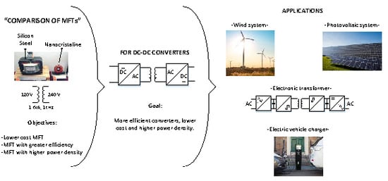
Funding

This research received no external funding.

Acknowledgments

The authors thank the TNM (Tecnológico Nacional de Mexico/Instituto Tecnológico de Morelia) and CONACYT for supporting our research and projects leading to the writing of the present paper.

Conflicts of Interest

The authors declare no conflict of interest.

References

  1. Wei, Q.; Wu, B.; Xu, D.; Reza, N. A Medium-Frequency Transformer-Based Wind Energy Conversion System Used for Current-Source Converter-Based Offshore Wind Farm. IEEE Trans. Power Electron. 2017, 32, 248–259. [Google Scholar] [CrossRef]
  2. Krishnamoorthy, H.; Rana, D.; Garg, P.; Prasad, N.; Pitel, I. Wind Turbine Generator-Battery Energy Storage Utility Interface Converter Topology with Medium-Frequency Transformer Link. IEEE Trans. Power Electron. 2014, 29, 4146–4155. [Google Scholar] [CrossRef]
  3. Blaabjerg, F.; Ma, K. Future on Power Electronics for Wind Turbine Systems. IEEE J. Emerg. Sel. Top. Power Electron. 2013, 1, 139–152. [Google Scholar] [CrossRef]
  4. Ozdemir, S.; Balci, S.; Altin, N.; Sefa, I. Design and Performance Analysis of the Three-level isolated DC-DC converter with the nanocrystalline core transformer. Int. J. Hydrogen Energy 2017, 42, 17801–17812. [Google Scholar] [CrossRef]
  5. Zhao, B.; Song, Q.; Li, J.; Liu, W.; Liu, G.; Zhao, Y. High-Frequency-Link DC Transformer Based on Switched Capacitor for Medium-Voltage DC Power Distribution Application. IEEE Trans. Power Electron. 2016, 31, 4766–4777. [Google Scholar] [CrossRef]
  6. Tian, H.; Wei, Z.; Vaisambhayana, S.; Thevar, M.; Tripathi, A.; Kjaer, P. A Coupled, Semi-Numerical Model for Thermal Analysis of Medium Frequency Transformer. Energies 2019, 12, 328. [Google Scholar] [CrossRef]
  7. Huang, P.; Mao, C.; Wang, D. Electric Field Simulations and Analysis for High Voltage High Power Medium Frequency Transformer. Energies 2017, 10, 371. [Google Scholar] [CrossRef]
  8. Wang, L.; Zhu, Q.; Yu, W.; Huang, A. A Medium-Voltage Medium-Frequency Isolated DC-DC Converter Based on 15-kV SiC Mosfets. IEEE J. Emerg. Sel. Top. Power Electron. 2016, 5, 100–109. [Google Scholar] [CrossRef]
  9. Krishnamoorthy, H.; Daniel, M.; Ramos-Ruiz, J.; Enjeti, P.; Liu, L.; Aeloiza, E. Isolated AC-DC Converter Using Medium Frequency Transformer for Off-Shore Wind Turbine DC Collection Grid. IEEE Trans. Ind. Electron. 2017, 64, 8939–8947. [Google Scholar] [CrossRef]
  10. Balci, S.; Sefa, I.; Altin, N. An Investigation of Ferrite and Nanocrystalline Core Materials for Medium-Frequency Power Transformer. J. Electron. Mater. 2016, 45, 3811–3821. [Google Scholar] [CrossRef]
  11. She, X.; Huang, A.Q.; Burgos, R. Review of Solid-State Transformer Technologies and Their Application in Power Distribution Systems. IEEE J. Emerg. Sel. Top. Power Electron. 2013, 1, 186–198. [Google Scholar] [CrossRef]
  12. Zhao, S.; Li, Q.; Lee, F.; Li, B. High-Frequency Transformer Design for Modular Power Conversion from Medium-Voltage AC to 400 VDC. IEEE Trans. Power Electron. 2017, 33, 7545–7557. [Google Scholar] [CrossRef]
  13. Balci, S.; Sefa, I.; Altin, N. Design and Analysis of a 35 kVA Medium Frequency Power Transformer with the Nanocrystalline core material. Int. J. Hydrogen Energy 2017, 42, 17895–17909. [Google Scholar] [CrossRef]
  14. Ohta, M.; Hasegawa, R.; Itabashi, H. Development of Block Cores Comprising High-Bs Nanocrystalline Alloy Ribbon. IEEE Trans. Magn. 2018, 54. [Google Scholar] [CrossRef]
  15. Kauder, T.; Hameyer, K. Iron Loss Comparison of Standard SiFe and Nanocrystalline Materials for Power Transformers in a Dual Active Bridge Converter. In Proceedings of the 18th European Conference on Power Electronics and Applications (EPE’16 ECCE Europe), Karlsruhe, Germany, 5–9 September 2016. [Google Scholar]
  16. Kauder, T.; Hameyer, K. Performance Factor Comparison of Nanocrystalline, Amorphous, and Crystalline Soft Magnetic Materials for Medium-Frequency Applications. IEEE Trans. Magn. 2017, 53. [Google Scholar] [CrossRef]
  17. Bahmani, M.A.; Thiringer, T.; Kharezy, M. Design Methodology and Optimization of a Medium-Frequency Transformer for High-Power DC-DC Applications. IEEE Trans. Ind. Appl. 2016, 52, 4225–4233. [Google Scholar] [CrossRef]
  18. Huang, P.; Mao, C.; Wang, D.; Wang, L.; Duan, Y.; Qiu, J.; Xu, G.; Cai, H. Optimal Design and Implementation of High-Voltage High-Power Silicon Steel Core Medium-Frequency Transformer. IEEE Trans. Ind. Electron. 2017, 64, 4391–4401. [Google Scholar] [CrossRef]
  19. Ruiz, D.; Venegas, R.; Anaya, R.; Moreno, E.; Rodríguez, R. Design and Prototyping Medium-Frequency Transformers Featuring a Nanocrystalline Core for DC-DC Converters. Energies 2018, 11, 2081. [Google Scholar] [CrossRef]
  20. Hilzinger, R.; Rodewald, W. Rapidly solidified amorphous and nanocrystalline materials. In Magnetic Materials, 1st ed.; Vacuumschmelze GmbH & Co. KG., Publicis Publishing: Erlangen, Germany, 2013; Volume 1, pp. 252–302. [Google Scholar]
  21. Soltau, N.; Eggers, D.; Hameyer, K.; Doncker, R.W.D. Iron Losses in a Medium-Frequency Transformer Operated in a High-Power DC-DC Converter. IEEE Trans. Magn. 2014, 50, 953–956. [Google Scholar] [CrossRef]
  22. Bahmani, M.A.; Thiringer, T. Accurate Evaluation of Leakage Inductance in High-Frequency Transformers Using an Improved Frequency-Dependent Expression. IEEE Trans. Power Electron. 2015, 30, 5738–5745. [Google Scholar] [CrossRef]
  23. Luciano, B.; Morais, M.; Kiminami, C. Single Phase 1-kVA Amorphous Core Transformer: Design, Experimental Tests, and Performance after Annealing. IEEE Trans. Magn. 1999, 35, 2152–2154. [Google Scholar] [CrossRef]
Figure 1. MFT design procedure.
Energies 12 02062 g001
Figure 2. MFT with a Full-Bridge Converter.
Energies 12 02062 g002
Figure 3. Geometric dimensions of, (a) the silicon steel core and, (b) the nanocrystalline core.
Energies 12 02062 g003
Figure 4. Core (Pc), winding (Pw) and, total (Pt) losses for both MFTs.
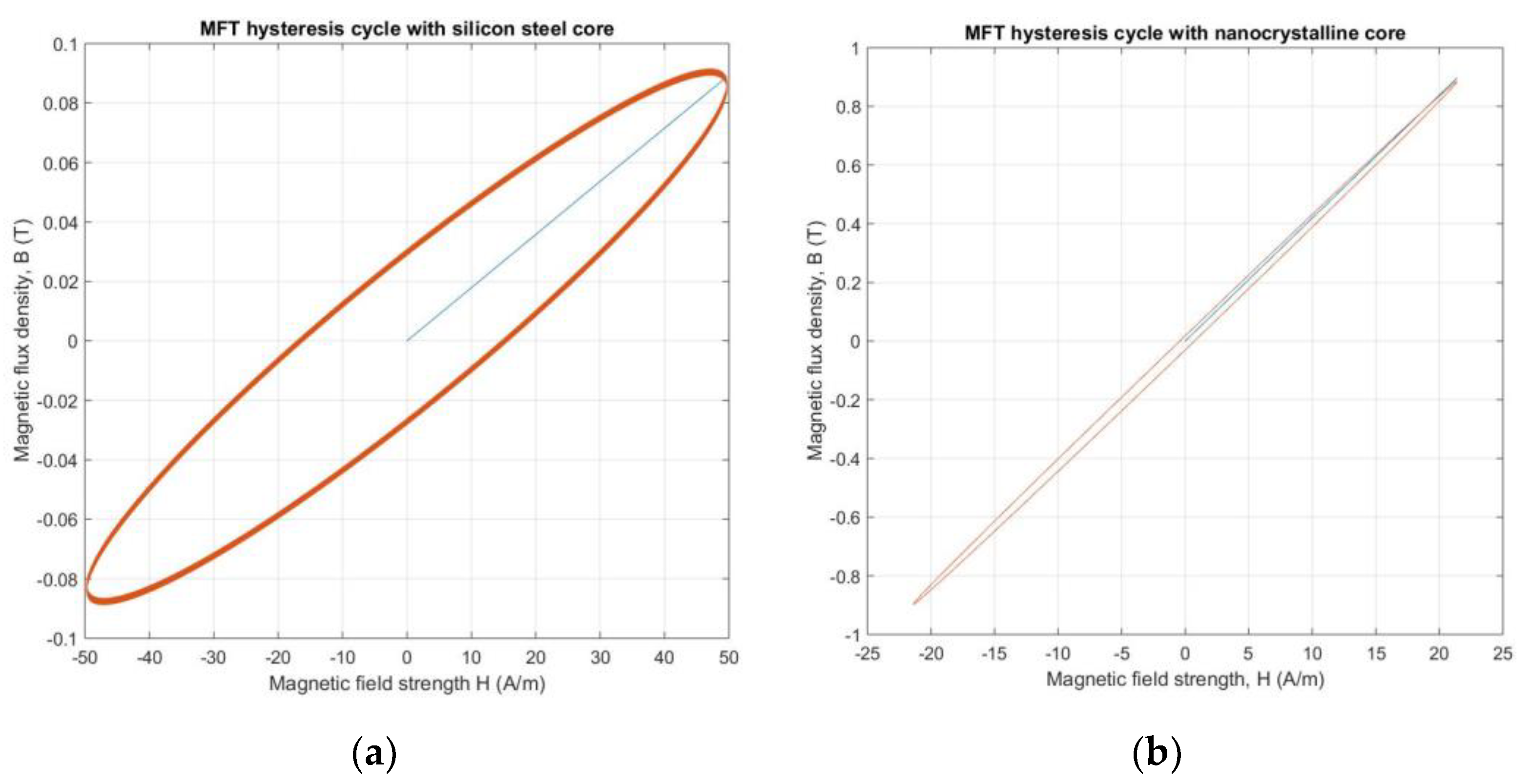
Energies 12 02062 g004
Figure 5. B(H) curves for the MFTs. (a) silicon steel core case, (b) nanocrystalline core case.
Energies 12 02062 g005
Figure 6. Diagram used for simulation of an MFT featuring a Full Bridge converter.
Energies 12 02062 g006
Figure 7. Input and output voltages for MFTs. (a) A silicon steel core and, (b) a nanocrystalline core.
Energies 12 02062 g007
Figure 8. Input and output currents for MFTs. (a) A silicon steel core and, (b) a nanocrystalline core.
Energies 12 02062 g008
Figure 9. MFT prototypes featuring: a nanocrystalline core (right), a silicon steel core (left).
Energies 12 02062 g009
Figure 10. 
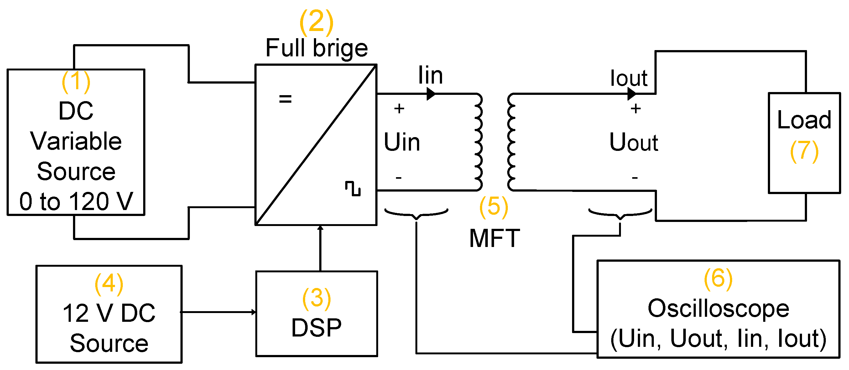
Lab MFT prototypes with a Full Bridge converter. (a) nanocrystalline MFT and (b) silicon steel MFT. (1) DC variable source from 0 to 120 V, (2) Full-Bridge converter, (3) DSP, (4) 12 VDC Source, (5) MFT, (6) Load, and (7) Oscilloscope.
Energies 12 02062 g010
Figure 11. Block diagram of the experimental setup.
Energies 12 02062 g011
Figure 12. Input and output voltages and currents for the MFT lab prototype with the nanocrystalline core: Uin (CH1), Iin (CH2), Uout (CH3), Iout (CH4).
Energies 12 02062 g012
Figure 13. Input and output voltages and currents for the MFT lab prototype with the silicon steel core: Uin (CH1), Iin (CH2), Uout (CH3), Iout (CH4).
Energies 12 02062 g013
Table 1. Characteristics of MFTs with silicon steel and nanocrystalline cores.
Core MaterialPower (kVA)Frequency (kHz)Flux Density (T)Power Density (kW/L)Efficiency
Silicon steel [18]3510.52.9699.40%
Silicon steel [9]0.80.60.61.2999.00%
Nanocrystalline [17]5050.911.599.48%
Nanocrystalline [19]150.915.0199.41%
Table 2. Characteristics of silicon steel and nanocrystalline materials for MFT design.
ParametersMaterial 1Material 2
MaterialNanocrystallineGrain-oriented silicon steel
(Vitroperm 500F, W531)
CoreLaminate (0.02 mm)Laminate (0.19 mm)
Maximum density flow1.2 T1.5–2.0 T
Permeability24,9201400
CostHighLow
Table 3. Geometrical dimensions of both MFTs.
DimensionsNanocrystalline Core (cm)Silicon Steel Core (cm)
A815.5
B59.5
C29
D-12
Table 4. Numerical values for the volumes of the core and windings for both MFTs.
VolumeSilicon Steel Core (cm3)Nanocrystalline Core (cm3)
Vc2223.2122.52
Vw1823.8274.89
Table 5. Weight comparison of MFTs.
MFTTotal Weight (kg)
Silicon Steel33.74
Nanocrystalline4.28
Table 6. Numerical values of Pc, Pw, and Pt for both MFTs.
VolumeMFT with Silicon Steel CoreMFT with Nanocrystalline Core
f1000 Hz1000 Hz
B0.1 T0.9 T
Pc13.06 w2.46 w
Pw160.53 w14.52 w
Pt173.60 w16.98 w
Table 7. Efficiency calculated for both MFTs.
MFT CoreEfficiency
Silicon steel82.64%
Nanocrystalline98.36%
Table 8. MFT building costs.
MFTTotal Cost of the MFT (CHF)Price Per Unit of Weight (CHF/kg)
Silicon steel39511.71
Nanocrystalline37587.62
Table 9. MFT model parameters used in computer simulations.
VariableMFT Silicon Steel CoreMFT Nanocrystalline Core
Pout1000 VA1000 VA
f1 kHz1 kHz
Uin120 V120 V
Uout240 V240 V
R11.47 Ω125 mΩ
R26.77 Ω430.4 mΩ
Ld10.990 mH12.49 μH
Ld24.537 mH49.41 μH
Rm79,657 Ω70,870 Ω
Lm151.9 mH309.2 mH
Table 10. Simulation results.
VariableMFT Silicon Steel CoreMFT Nanocrystalline Core
Uin120 V120 V
Uout196.40 V237.9 V
Iin6.60 A7.95 A
Iout3.27 A3.96 A
Efficiency81.09%98.75%
Table 11. Experimental results, nominal load (60 Ω).
VariableMFTMFT
Silicon Steel CoreNanocrystalline Core
Uin120 V118 V
Uout211 V245 V
Iin7.50 A8.61 A
Iout3.42 A4.11 A
Efficiency80.18%99.11%
Table 12. Experimental results, a half nominal load of 120 Ω.
VariableMFTMFT
Silicon Steel CoreNanocrystalline Core
Uin120 V117 V
Uout238 V239 V
Iin4.28 A4.19 A
Iout1.98 A2.03 A
Efficiency91.75%98.96%
Table 13. Distinct methods for designing MFTs featuring silicon Steel and nanocrystalline cores.
MaterialMethodPowerFrequencyPower DensityEfficiency
NanocrystallineProposed in [19]1 kVA1 kHz2.51 kW/l99.11%
Silicon steel“classical design method” [10]1 kVA1 kHz0.25 kW/l80.18%
Silicon steelProposed in [18]35 kVA1 kHz2.96 kW/l99.40%
Silicon steelProposed in [9]0.8 kVA600 Hz1.29 kW/l99.00%
NanocrystallineProposed in [17]50 kVA5 kHz11.5 kW/l99.48%
NanocrystallineProposed in [19]1 kVA5 kHz15.01 kW/l99.41%

