1. Introduction
Since the limitation of the fossil fuel becomes a public concern, renewable energy is getting more and more attention in recent years. As one of the most dominant renewable sources, wind energy is extensively exploited in power system. In the meantime, the power grid is faced with a series of challenges brought by wind turbines. Especially, the introduced low voltage ride-through (LVRT) issue is a major cause of generator-shedding and power system stability. In order to support the voltage during grid fault, numerous power utilities put forward strict grid codes which require wind turbines not only to remain connected with the power grid but also inject reactive current into the grid [
1].
The doubly-fed induction generator (DFIG) is widely used in wind power generation systems due to its several advantages, such as variable speed operation. However, when a grid fault occurs, the DFIG is faced with the danger of overcurrent on both stator and rotor sides [
2] for its sensitivity to grid fault. Insulated gate bipolar transistors (IGBTs) of the rotor side converter (RSC) may be damaged by the impact current. In addition to overcurrent, the DC-link overvoltage also threatens the security of the DFIG [
3].
Several approaches have been presented to protect the DFIG and enhance its LVRT capability. A widely applied method is crowbar protection in rotor circuit [
4], which has a simple structure and restrains the overcurrent effectively. However, the RSC is blocked when crowbar is active. In this circumstance, the DFIG operates as an induction machine and consumes reactive power from the power grid [
5] which deepens the voltage sag. A capacitor in series with crowbar circuit is proposed to eliminate the ripples in the rotor circuit and DC-link in [
6]. This reduces crowbar operating time but cannot avoid blocking the RSC. Employing a series dynamic braking resistor (SDBR) in the stator or rotor circuit, as in [
7,
8,
9], improves transient responses under a grid fault and avoids blocking the RSC. In addition, stator SDBR restrains the rotor current and DC-link voltage significantly and promotes the terminal voltage [
8]. However, the stator SDBR absorbs active power and rotor SDBR may cause a high rotor voltage [
10]. In [
11], a dynamic voltage restorer (DVR) is adopted, which compensates the grid voltage and allows the DFIG operates uninterruptedly. Simultaneously, the DVR increases the cost and complexity of the DFIG. Combining with crowbar circuit, a R-L impedance circuit in series with rotor circuit was introduced in [
12,
13], which maintains the RSC partial connection to the rotor. In order to retain the control of the RSC and enhance the transient performance during the fault grid, the protection circuit is still expected to be improved. The fault current limiter is adopted in [
14,
15,
16,
17] to limit the fault current and enhance the LVRT ability. In [
18,
19,
20], the control strategies of the RSC are proposed, which controls the RSC generating the rotor current for demagnetizing.
This paper proposes an improved configuration to enhance the LVRT capability of the DFIG and avoid blocking the RSC. A corresponding control strategy is also provided. The proposed configuration is composed of a crowbar and a rotor braking resistor array in series with the rotor circuit between the crowbar and the RSC. The series rotor braking resistor array restrains the RSC current below the maximum current of the IGBTs. Using the crowbar circuit as a part of the protection, the proposed method cannot avoid absorbing reactive power due to the crowbar current, which would reduce the effect of reactive power control. It can be solved partly through an appropriate selection of parameters. The rotor current is calculated and the parameter selection principle is given, by which the rotor current and RSC current remains at an appropriate value.
To improve the transient performance, a corresponding self-adaptive control is employed, which regulates the rotor braking resistance and protection exiting time automatically according to the fault situation and calculation results in the LVRT process. Finally, a 1.5 MW DFIG simulation model is developed to validate the effectiveness of the proposed configuration and control strategy. Compared with the conventional crowbar protection, the fluctuation of the rotor current and the electromagnetic torque under the proposed protection is slightly larger due to the operation of the RSC and the variation of the resistor array. However, the RSC is blocked in the conventional crowbar protection, which brings trouble to the DFIG. Employing the proposed configuration, the control of the RSC is retained. As a result, the reactive power control of the DFIG can be carried out and the grid voltage is supported during the fault period. Additionally, the comparisons of the simulation results also show that the self-adaptive control avoids the repeated operation of the protection and accelerates the damping of the stator flux linkage.
2. Mathematical Model of the DFIG
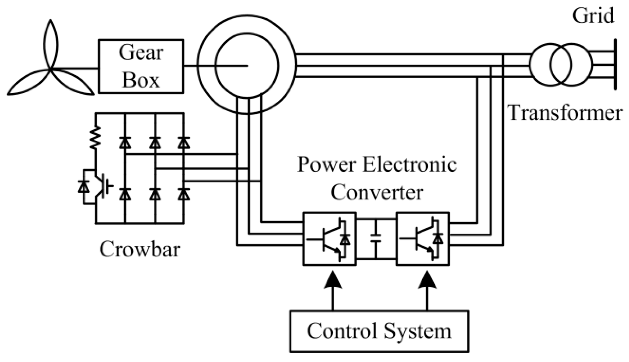
The structure of wind power system driven by the DFIG is described in
Figure 1, which is composed of a wind turbine, gear box, DFIG, power electronic converter, and control system [
21].
The stator of the DFIG is connected with the power grid directly and the rotor is connected with the power grid through a power electronic converter which consists of the RSC and the grid side converter (GSC) [
22]. When the DFIG is operating, both stator and power electronic converter can exchange power with the power grid. The power flow of the power electronic converter tends to be static when the generator is operating synchronously. Through the control system, the amplitude and frequency of rotor voltage is controlled and variable speed operation is realized.
Using the Park’s model, voltage equations can be described as in a d-q synchronous reference frame:
where
us and
ur are the stator and rotor voltage vector, respectively.
is and
ir are the stator and rotor current vector, respectively.
ω1 is the synchronous angular speed and
s is the slip ratio.
Flux linkage equations can be described as well in Equation (2)
where
ψs and
ψr are the stator and rotor flux linkages, respectively;
Lm is the magnetizing inductance,
Ls is the total inductance in stator circuit, and
Lr is the total inductance in rotor circuits.
Employing grid voltage orientation, the active and reactive power produced by stator is written as follows:
From Equation (3), it can be concluded that the active power and reactive power of stator are controlled by the rotor current. A similar conclusion can also be obtained in the GSC:
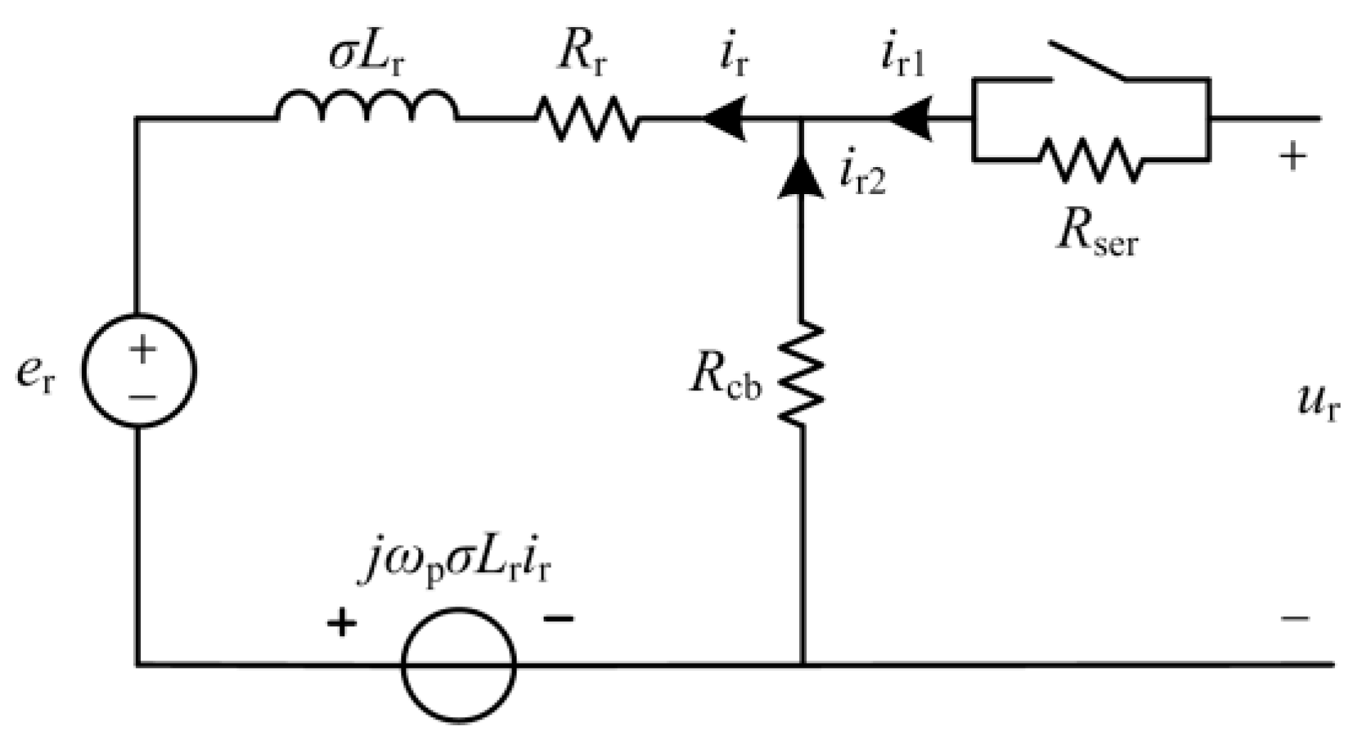
Combining Equation (1) with (2), the rotor voltage can be expressed as follows:
where
ωp is slip angular speed;
er is the rotor induced voltage that affected by stator flux linkage through:
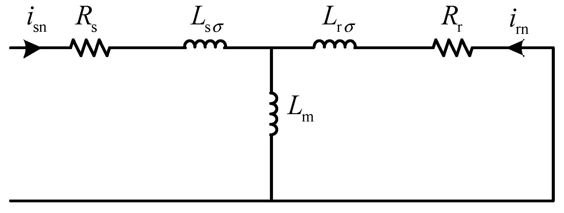
According to Equation (5), the rotor equivalent circuit of the DFIG is presented in
Figure 2, where
.
During the fault period, the stator flux linkage used the synchronous reference frame is:
where
Us0 is steady-state voltage and
Ts is stator time constant.
Kd is the depth of voltage sag and it can be expressed as:
where
Us is the fault voltage. Hence, Equation (6) becomes:
where
λ = −
jωs − 1/
Ts. The
erof is the steady-state component of
er and the
eron is the transient component that decreases exponentially.
As it is shown in Equations (7)–(11), when a grid fault occurs, the stator flux linkage increases and then the rotor induced voltage increases. However, the RSC cannot provide a corresponding exciting voltage, thus, an overcurrent is produced in rotor circuit. The IGBTs of the RSC may be damaged if the overcurrent exceeds the safety threshold and, hence, protection is necessary.
3. Improved Rotor Braking Protection
This section introduces an improved configuration of rotor braking protection firstly. In addition, to prove the effectiveness of the proposed circuit, the equivalent circuit and related theoretical calculations are given. The parameter selection principle is also presented in the last section.
3.1. Proposed Configuration
As what is analyzed in
Section 2, protection should be applied during the fault time. The crowbar circuit is a prevalent method for DFIG protection. When the crowbar is operating, the crowbar resistor is connected with the rotor circuit and rotor current is restrained. However, to protect the RSC, the RSC is blocked in the crowbar operating period and the DFIG operates as an induction machine, which absorbs reactive power from the grid and deepens the voltage sag.
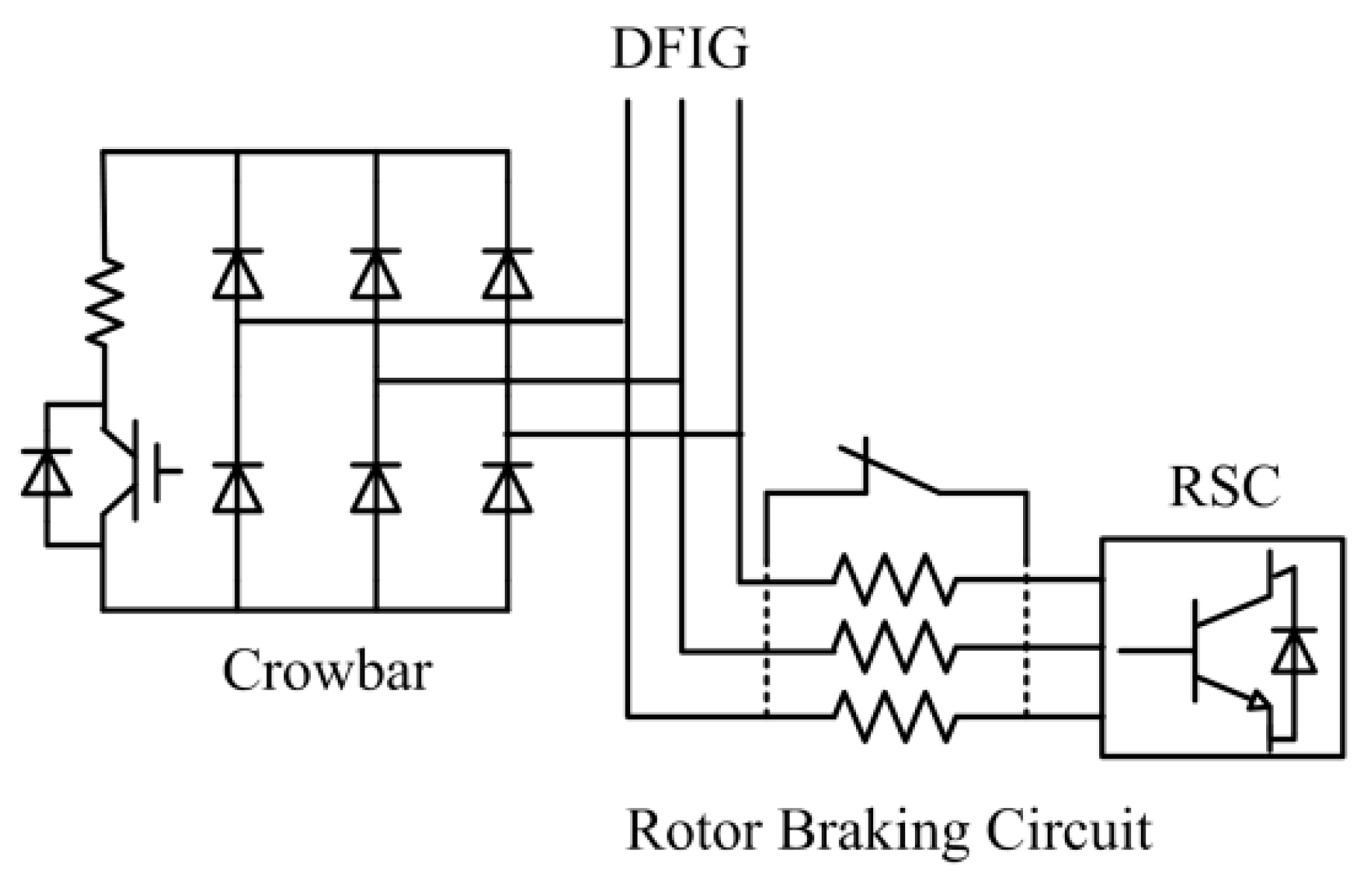
To avoid blocking the RSC and enhance the LVRT capability of the DFIG, an improved configuration of the protection circuit is proposed in
Figure 3. It is composed of two sections: (1) a crowbar circuit, and (2) a series rotor braking circuit.
A rotor braking circuit in series with the rotor circuit between the RSC and crowbar circuit is presented. The series rotor braking circuit is shortened by a switch normally and the switch would break during the grid fault period. When the rotor braking circuit operates solely, the RSC current would be restrained below the maximum current of the RSC. As a result, the RSC avoids being blocked and its control is retained.
As it is explained above, that the variation of
er causes rotor overcurrent, the damping of the rotor current is closely related to the structure of the rotor circuit. When the rotor braking circuit operates solely, the rotor current can be written as follow:
where
Rser is the rotor braking resistance. Solving the differential equation in Equation (12), it can be found that the rotor current decreases exponentially with the stator time constant
Ts and rotor time constant
Tr. The rotor time constant is:
The less the rotor time constant is, the faster the rotor transient current dampens. With the operation of the series resistor, the rotor resistor increases equivalently and, therefore, the rotor time constant decreases, which is beneficial for the protection.
According to Equation (1) and Equation (2), the stator equivalent circuit of the DFIG is shown in
Figure 4.
The rotor resistor can be ignored and the rotor current is written as:
According to Equations (2) and (14), the stator flux linkage becomes:
where
Ls′ is the equivalent stator inductor. As a result, the stator time constant can be expressed as:
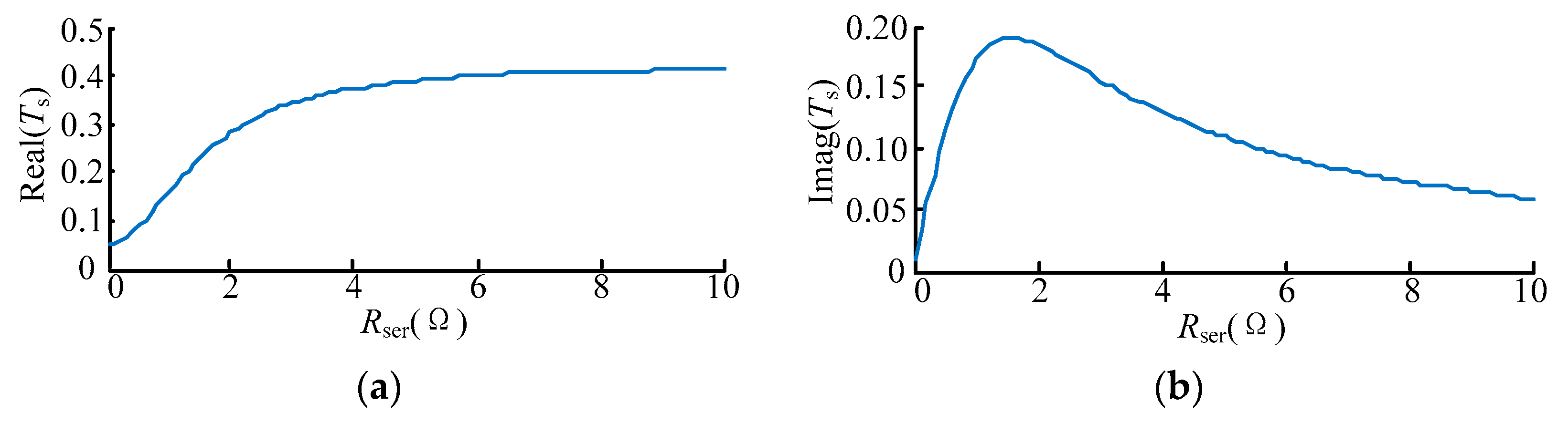
When the rotor braking circuit is operating, the resistor of the rotor circuit cannot be ignored due to the high value of the rotor braking resistor. Equations (14)–(16) are changed as follows:
The variation of stator time constant with rotor braking resistor is shown in
Figure 5. Comparing Equation (16) with Equation (19), it can be found that the rotor braking resistor enhances the real part of the stator time constant. The imaginary part of stator time constant has a maximum that can be ignored in the calculation. As a result, the transient stator flux linkage and the part of the rotor current that decrease with the stator time constant dampens slowly, which is harmful to the protection.
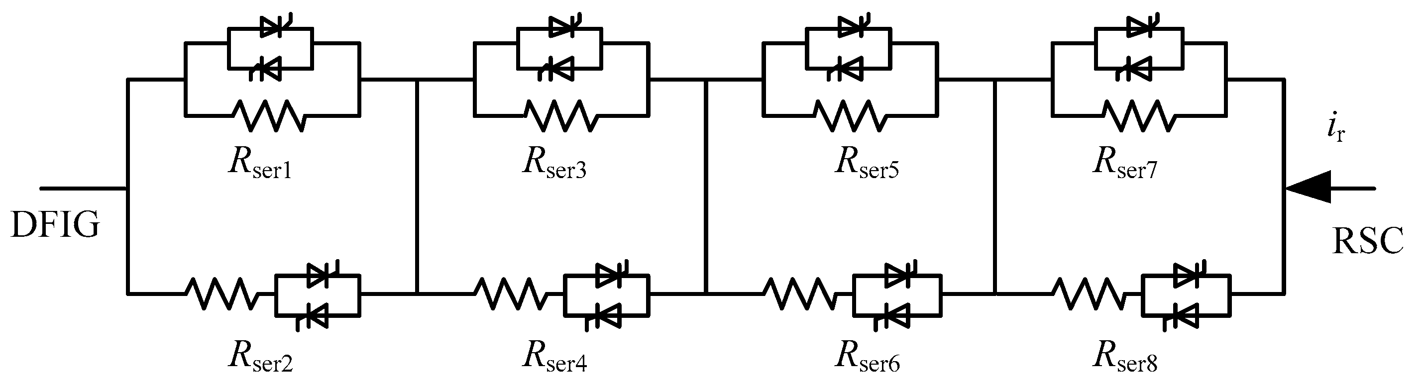
In this circumstance, to prevent the stator time constant becomes too large to affect the protection, the resistor should be optimized rather than fixed in different grid faults. As a result, a rotor braking resistor array is proposed in
Figure 6. The equivalent resistance of the resistor array can be regulated through the switch. When a slight fault occurs, a low equivalent resistance is adopted so that the stator time constant cannot be enhanced too much.
In order to further decrease the stator time constant and improves the damping speed, a crowbar circuit is proposed operating with the rotor braking circuit. The crowbar circuit is helpful to consume the excess energy in the rotor circuit and relieves the effect brought by the enhancement of the stator time constant. When the crowbar and the rotor braking resistor are operating together, the stator time constant becomes:
where
Rcb is the equivalent resistor of the crowbar circuit in the AC side. It can be found that the stator time constant in Equation (20) decreases due to the crowbar operation, which is helpful to the protection.
3.2. Rotor Current Calculation and Parameter Selection Principle
When the proposed protection operates, the rotor equivalent circuit of the DFIG in
Figure 2 can be redrawn as shown in
Figure 7.
The rotor current can be written as:
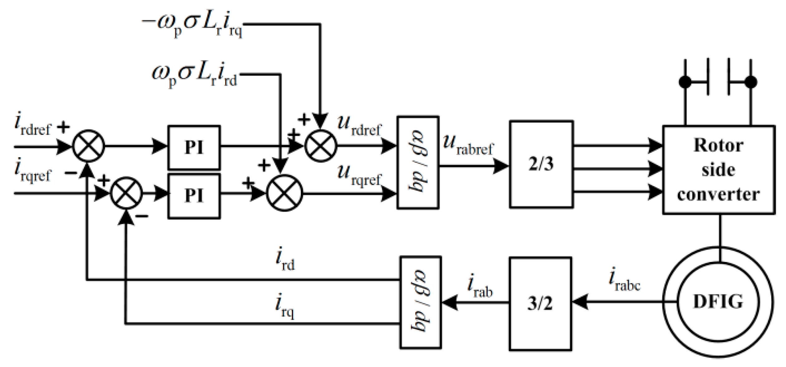
The control diagram of the RSC is shown in
Figure 8 [
23].
The rotor voltage can be expressed as:
where
Kp and
Ki are the parameters of the PI controller.
ir_ref is the reference of the rotor current. According to Equations (21) and (22), the differential equations are given:
The analytical solution can be derived from Equations (7) and (23) and a parameter selection principle may be obtained. However, the analytical solution is a complex and long expression which makes it difficult to analyze the relation between the rotor current and the protection parameters. Compared with the analytical solution, the numerical solution is much simpler and has a clear expression. It is easy to obtain the curve that expresses the variation trend between the maximum rotor current and protection parameters, which provides a basis for protection parameter selection.
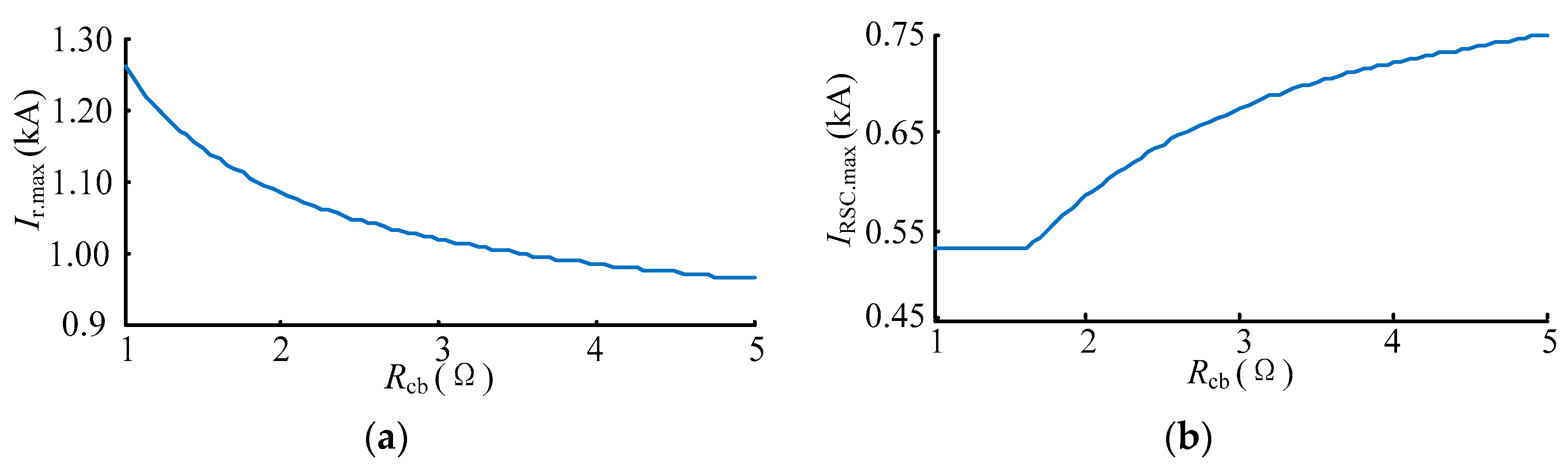
Taking a steady rotor current and the steady rotor voltage as the initial value of the numerical calculation, the rotor current and the RSC current is obtained through solving Equation (23). The calculation results are shown in
Figure 9 and
Figure 10, which shows the variation of maximum transient rotor current under different protection parameters. With the increasing of
Rcb and
Rser, rotor current in
Figure 9a and
Figure 10a decreases obviously. This proves the effectiveness of the proposed protection. However, in
Figure 9b and
Figure 10b, the RSC current increases with the increasing of
Rcb. If a safety threshold of the rotor current is set, the protection parameters are determined in
Figure 9 and
Figure 10.
During the fault time, the rotor current is divided into two parts: the crowbar current and the RSC current. The RSC current controls the active and reactive power that stator generates. However, the crowbar current forces a part of the DFIG to operate as an induction machine, which is likely to be the conventional crowbar protection, and absorbs reactive power from the grid. Therefore, the parameter selection of the protection circuit ought to follow:
- (1)
The Rser and Rcb should be large enough to restrain the overcurrent and the Rser cannot be quite as large, otherwise the control effect of the RSC would be poor due to the low RSC current.
- (2)
The Rcb cannot be quite as large, otherwise the RSC current would exceed the safety threshold.
- (3)
The Rser ought to be less than Rcb. If Rcb is much less than Rser, the DFIG almost operates as an induction machine. However, if Rser is much less than Rcb, the RSC current may exceed the threshold value and the IGBTs are threatened to be damaged.
4. Corresponding Self-Adaptive Control Strategy
Normally, the rotor braking circuit protection circuit operates when the rotor current exceeds the safety threshold and quits operation when the rotor current is under the safety threshold. However, the rotor current may exceed the safety threshold repeatedly, which causes the repeating operation of the rotor braking circuit and cause electromagnetic impact on the DFIG.
To solve this issue, a self-adaptive control strategy is proposed, which controls the rotor braking circuit operating for the long-term. Moreover, to decrease the stator time constant and prevent the rotor current from being restrained excessively in the protection process, the equivalent resistance of the rotor braking resistor array would decreases gradually.
As a result, in the process of long-term protection, the value of protection resistance should be adjusted adaptively. The resistance that adopted should be obtained according to the maximum value of the RSC current after adjusting the resistance. Assuming that the resistance is adjusted at time
tn1, the stator transient flux linkage becomes:
where
is the stator time constant before adjustment and
is the stator time constant after adjustment. The stator transient flux linkage would dampen with
after
tn1. The rotor current, RSC current, and rotor voltage at
tn1 can be measured, and then the RSC current is calculated through solving numerical solution of Equation (23). If the RSC current does not exceed the safety threshold, this resistance is adopted. If not, anther resistance is given and the RSC current should be calculated once again.
For the proposed protection, the selection of protection exiting time is particularly important. If the protection exits too early, it would easily lead to the overcurrent again, and then the protection operates which causes unnecessary impact on the system.
If the protection exits late, it will affect the stability of the system and the control effect. Therefore, it is necessary to optimize and adjust the exiting time of protection during different faults. In order to obtain the optimal moment of protection resection, it is necessary to calculate the secondary overcurrent of the RSC after exiting. Assuming that the protection exits at the time
tx, the stator transient flux linkage becomes:
where
Tx is defined as the transient damping coefficient:
where
(
i = 1, 2, …) is the stator time constant in the process of the protection resistance variation. Measuring the rotor current, RSC current, and rotor voltage at
tx, the RSC current can be calculated through solving the differential equation in Equation (23).
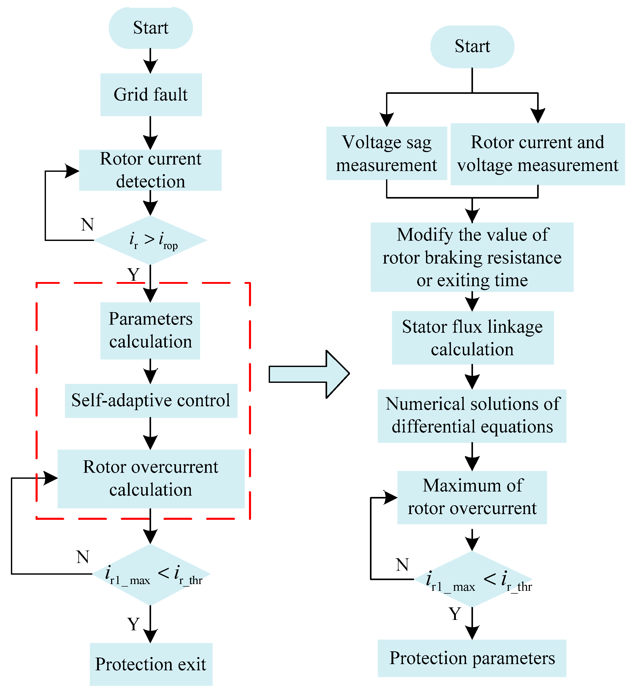
The flow diagrams of self-adaptive control and calculation are illustrated in
Figure 11. The proposed control consists of the following four parts:
- (1)
Protection operation: When the fault of external power grid causes voltage sag, it will cause the rotor overcurrent of the DFIG. The protection would operate at the time that a rotor overcurrent exceeds the action value.
- (2)
Calculation of resistance: The resistance should be calculated before protection operation according to voltage sag depth, rotor current, and voltage.
- (3)
Adaptive adjustment of rotor braking resistance: The long-term protection and adaptive adjustment of resistance value is adopted. During the protection process, the protection resistance decreases once in a power frequency cycle.
- (4)
Protection exiting: Assuming that the protection exits at the current moment, the RSC overcurrent after the exiting is calculated according to the calculation flow. If the calculation result meets the safety threshold, the protection can exit at this moment.
5. Proposed Protection Performance
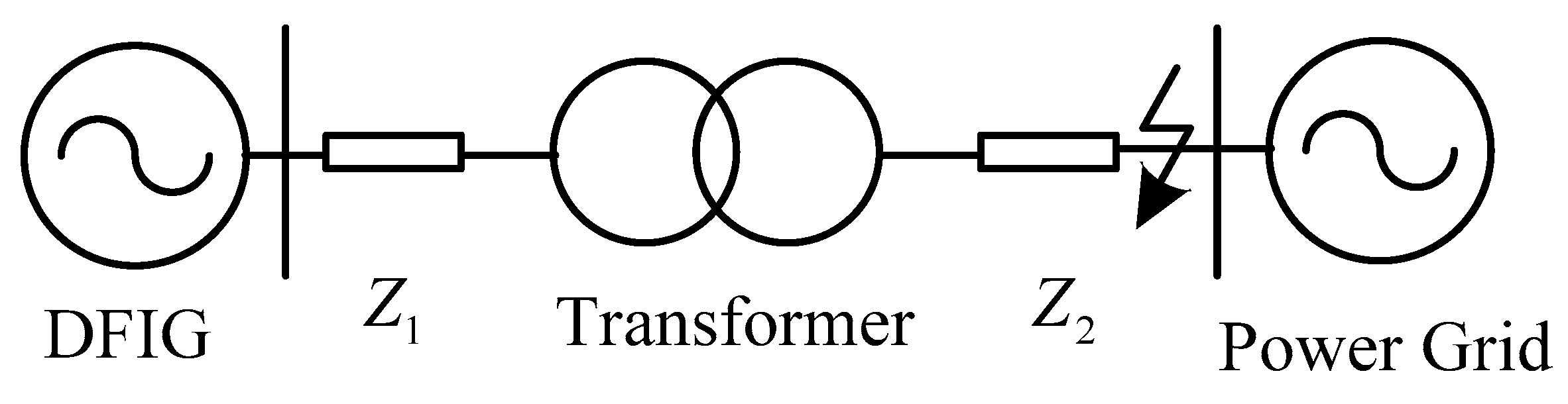
To verify the effectiveness of the proposed protection circuit and corresponding control strategy, a 1.5 MW DFIG simulation model is employed in
Figure 12. The wind speed is maintained at 13m/s and the slip rate is −0.2. A symmetrical voltage dip at grid occurs at 2 s and continues for 0.5 s.
The parameters of the DFIG, transformer, and power grid are shown in
Table 1:
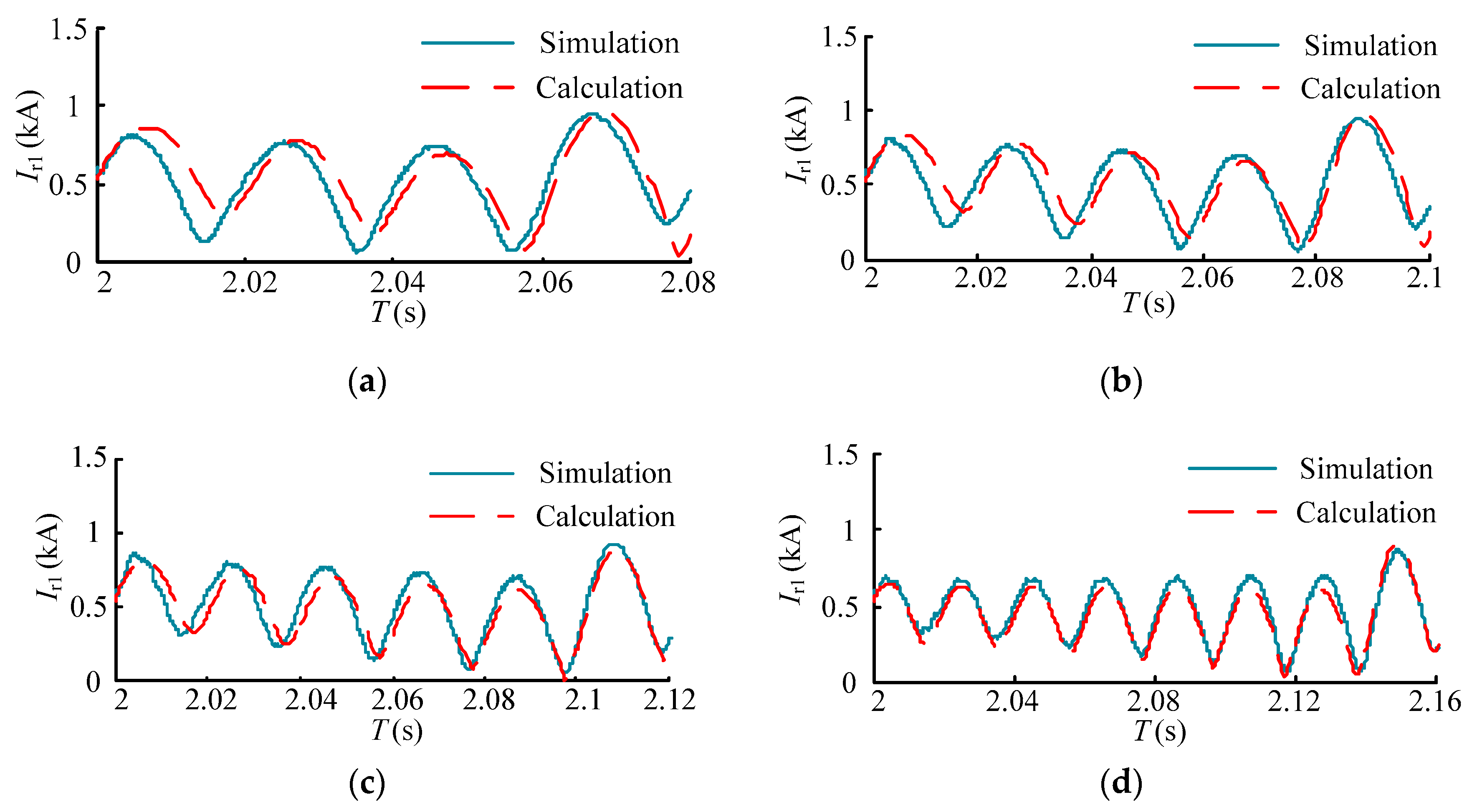
The comparisons of the RSC current under different voltage sags between simulation and calculation are shown in
Figure 13. Ignoring the impedance of the transformer and line, the calculation results are the numerical solution of the rotor current gained according to the rotor current calculation method shown in
Section 3 and
Section 4. The simulation results are gained in simulation platform according to the simulation model. It can be found that the variation tendency and value of the calculated results are close to the simulation results. When the protection exits, the calculated RSC overcurrent is also similar to that in the simulation. As a result, the calculation method introduced in
Figure 11 can be used in the self-adaptive control and the parameters of protection can be optimized.
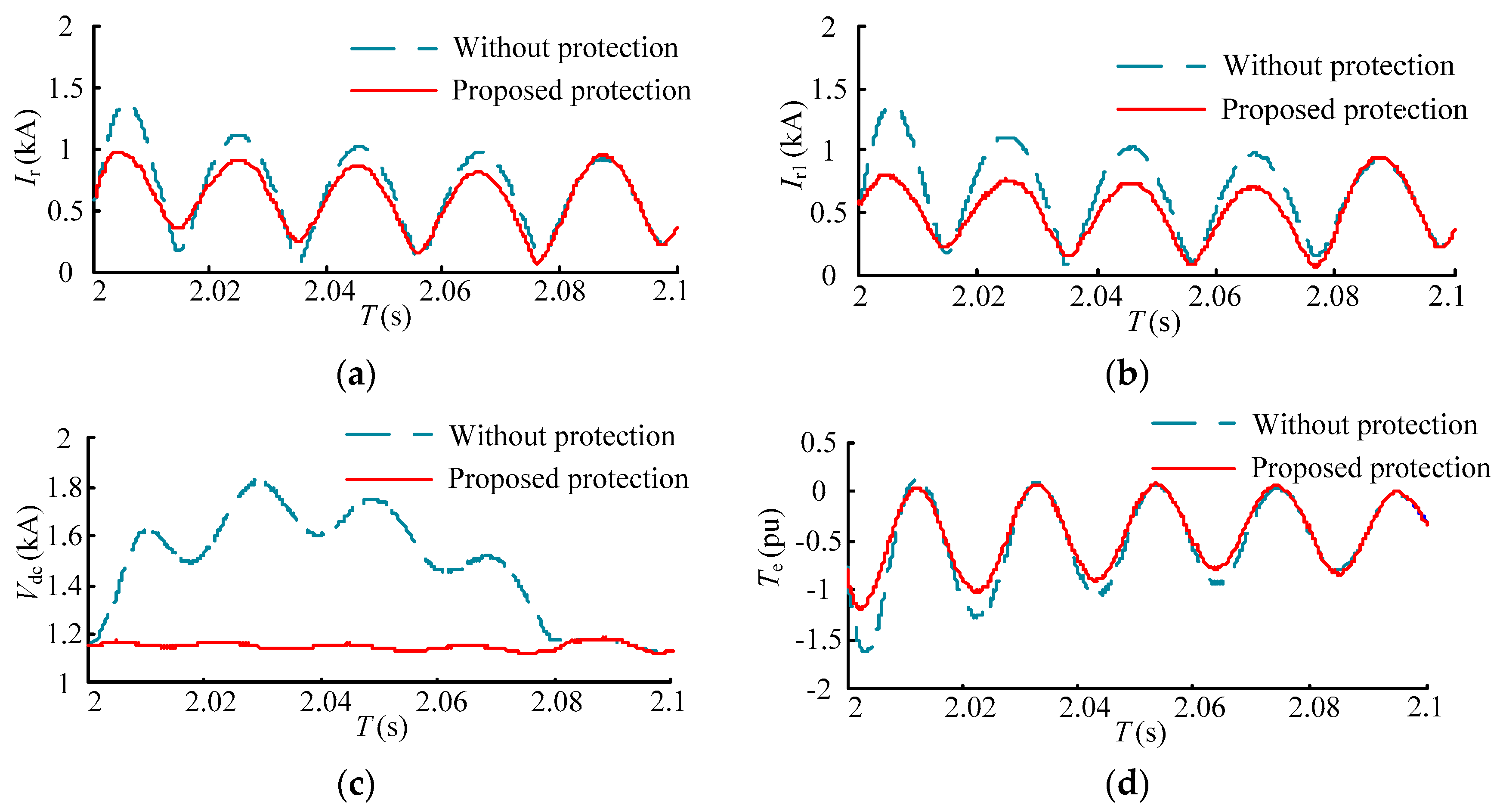
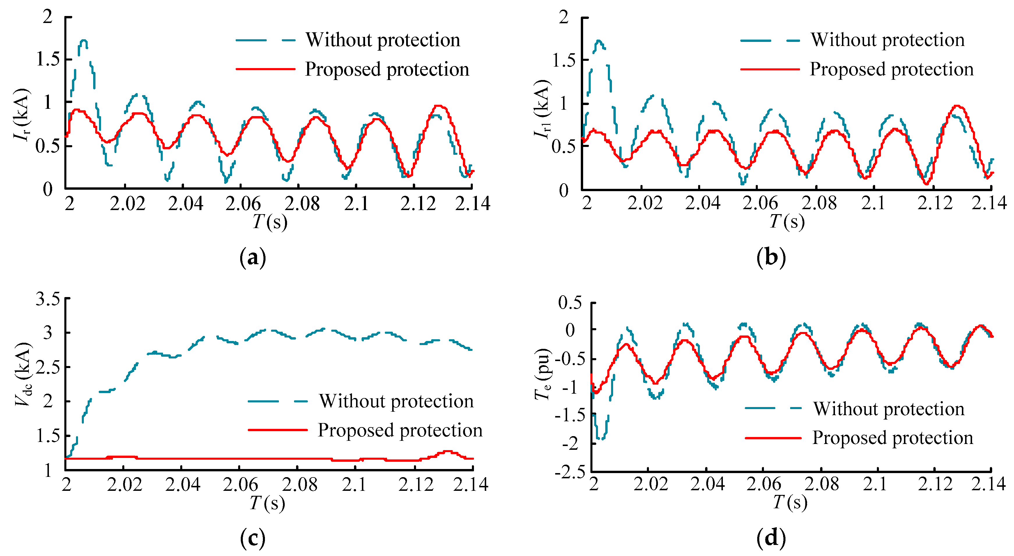
The performances of the proposed protection with the corresponding self-adaptive control strategy under different voltage sags are shown in
Figure 14 and
Figure 15. The transient responses without any protection are also shown. The resistance of rotor braking circuit changes gradually every 0.2 s and the protection exits at 2.08 s and 2.14 s. The DC-link overvoltage and rotor overcurrent are surely threatening the security of DC-link bus and RSC without any protection. In the proposed protection, the overcurrent and overvoltage are restrained effectively. The impact of electromagnetic torque is also restrained. Moreover, the RSC avoids being blocked and the value of the RSC current is below 0.8 kA, which guarantees the IGBTs are not be damaged and the RSC operates normally. The ripples of the RSC current and rotor current are also restrained with the proposed protection.
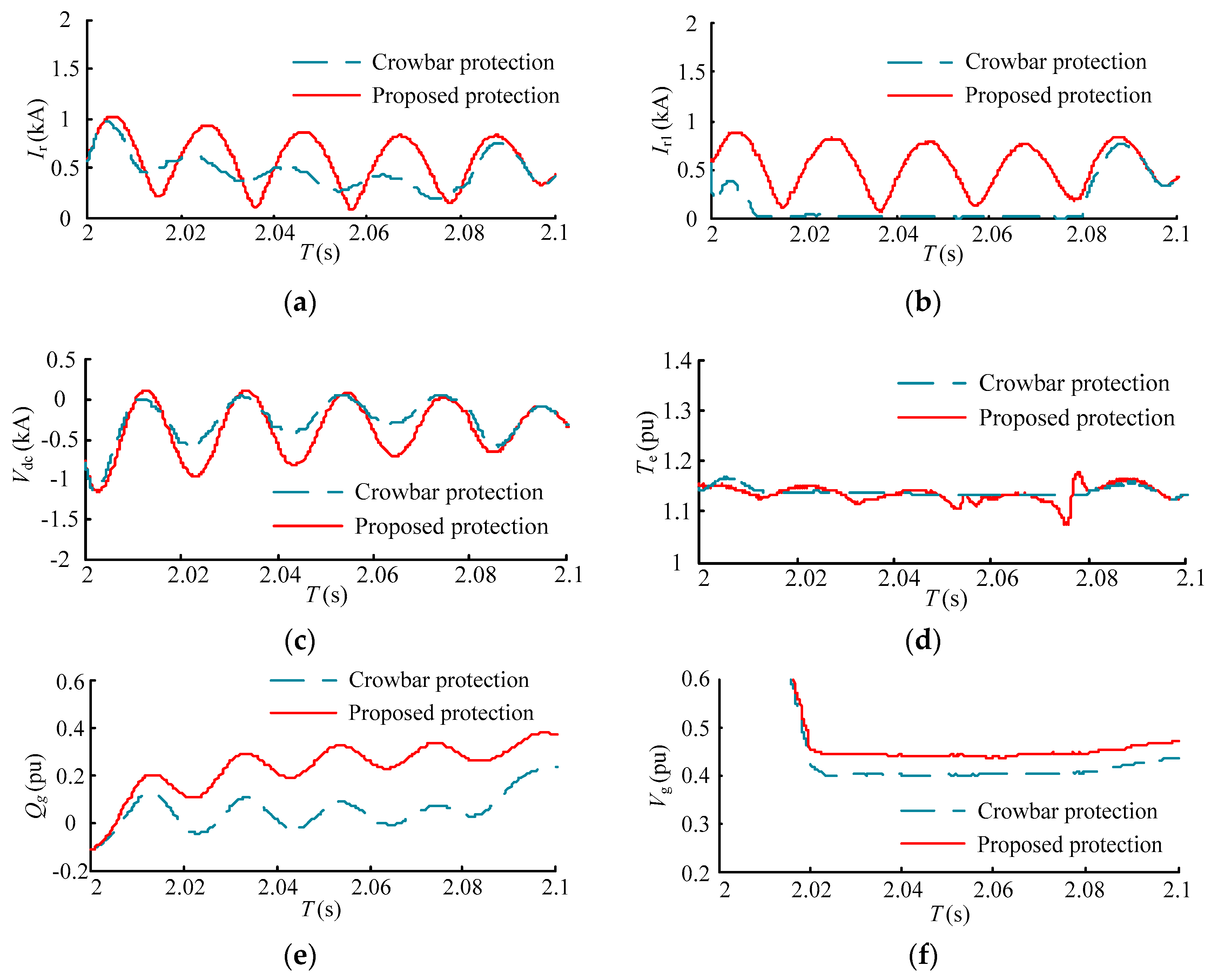
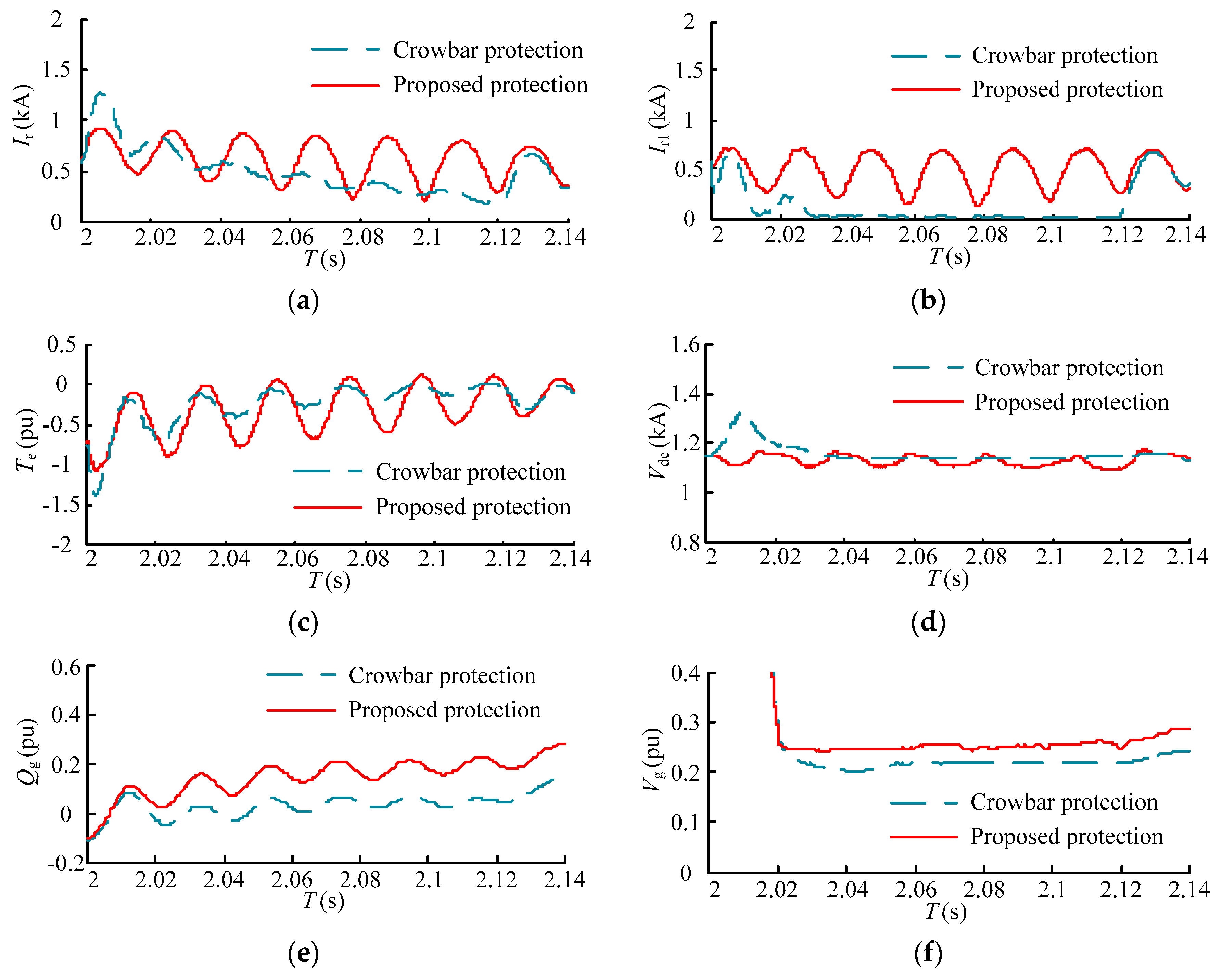
The comparisons between proposed protection and conventional crowbar protection are shown in
Figure 16 and
Figure 17. Although the conventional crowbar protection restrains the rotor current, DC-link bus voltage, and electromagnetic torque effectively, the PWM signals of the RSC are locked to protect the IGBT. As a result, the DFIG loses the reactive power control ability and operates as a induction motor, which may consume reactive power and deepen the voltage sag.
When the proposed protection is adopted, the rotor overcurrent and DC-link bus overvoltage are also avoided. Moreover, the reactive power control ability of the DFIG is retained during the protection operation. As a result, the rotor current is larger than that under crowbar protection. In
Figure 16e,f below, the DFIG generates 0.3 pu of reactive power to the grid and the terminal voltage is enhanced 0.05 pu. This cannot be ignored if each DFIG of a large-scale wind farm generates reactive power.
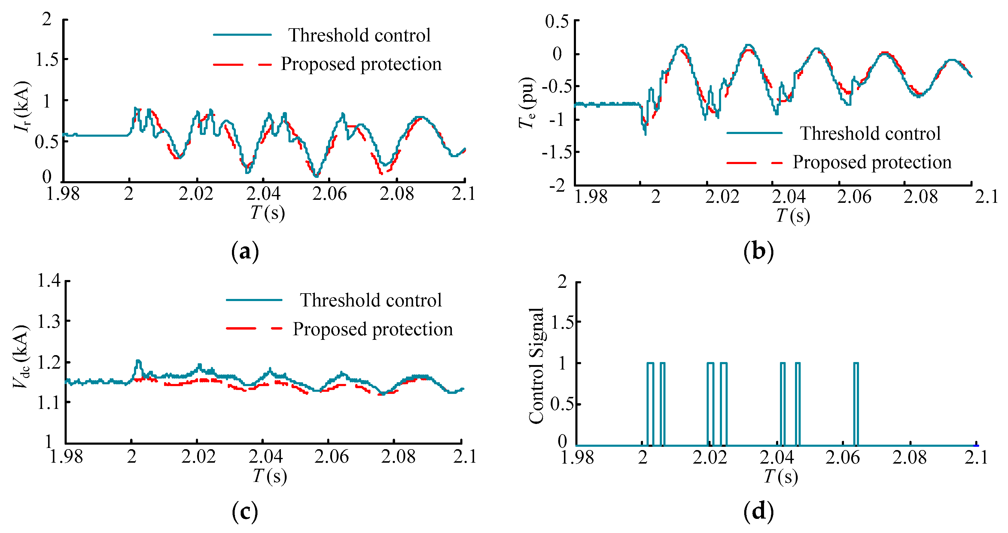
In [
7], the rotor braking resistor and chopper protection are adopted for the LVRT. The operation of the protection is controlled by a safety threshold. The protection operates at the moment that the rotor current or the DC-link bus voltage exceeds the safety threshold and exits at the moment that the rotor current or the DC-link bus voltage is under the safety threshold. The comparisons between protection in [
7] and the proposed protection in this paper are shown in
Figure 18 and
Figure 19.
From
Figure 18d and
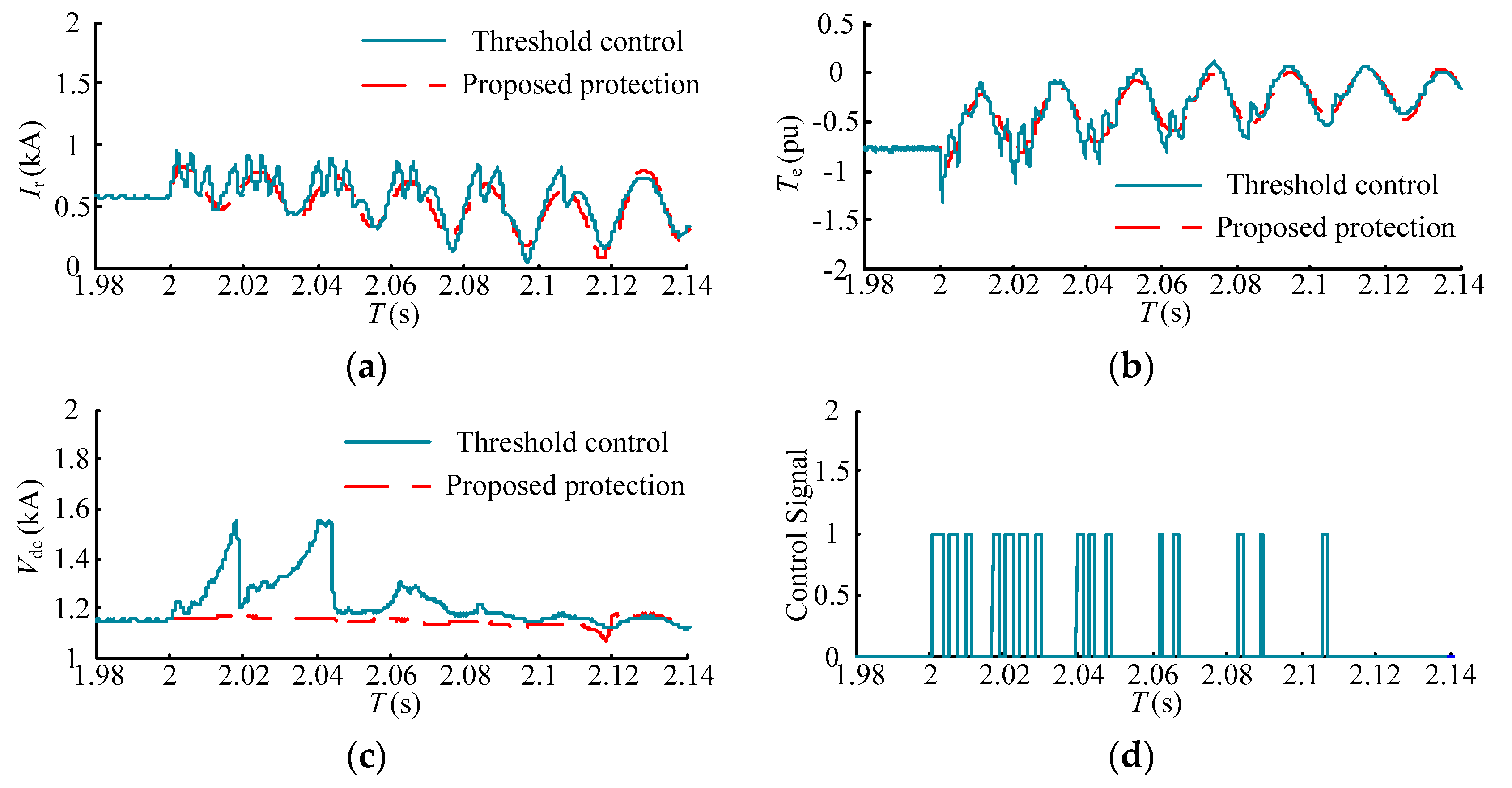
Figure 19d, the protection operates and exits repeatedly during the fault period, which causes several impacts of the rotor current and electromagnetic torque. Additionally, the DC-link bus voltage reaches the operating value of the chopper protection and the chopper protection operates under a voltage sag of 0.8. However, the proposed protection operates for the long-term and ensures the rotor current is smooth. As a result, several impacts are avoided. Moreover, the DC-link bus voltage is retained around the steady-state value under the proposed protection, which does not need the coordination of chopper protection.
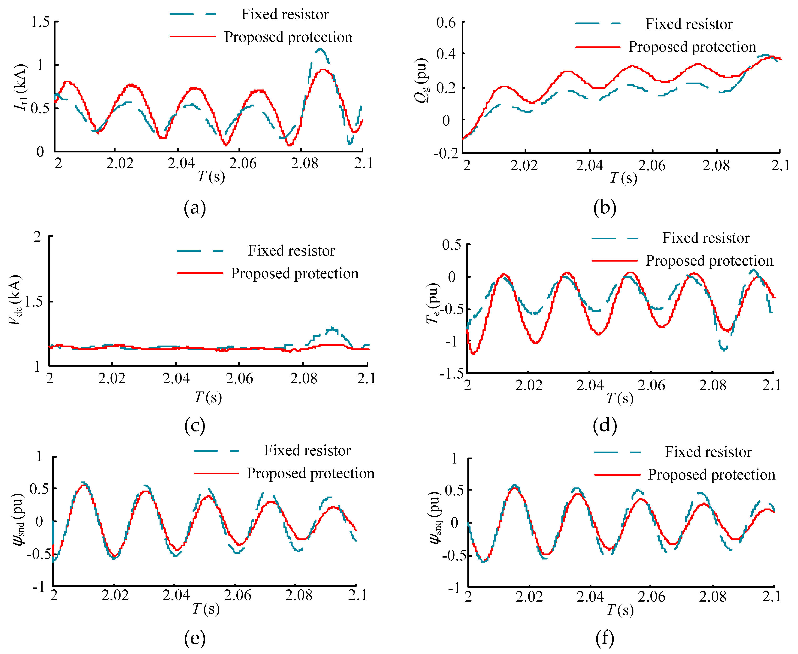
The comparison of the performance between proposed protection and the fixed rotor braking resistor is shown in
Figure 20. A fixed resistor can restrain the rotor overcurrent, DC-link bus overvoltage, and the impact of electromagnetic torque more effectively. However, The RSC current is restrained excessively under a fixed resistor and, hence, the reactive power is lower than that under the proposed method. The stator transient flux linkage damps slowly due to the fixed resistor. As a result, the rotor current exceeds the safety threshold and the DC-link bus voltage is enhanced after the fixed rotor braking resistor, exiting at 2.08 s. The proposed protection control the switch of the resistor array and the equivalent resistance decreases gradually, which ensures that the rotor current is maintained at the appropriate value and the stator transient flux linkage damps quickly. Moreover, the crowbar also decreases the stator time constant and further accelerates the damping of the stator time constant. Therefore, the rotor current cannot exceed the safety threshold after 2.08 s.
6. Conclusion
In order to enhance the LVRT ability of the DFIG, an improved rotor braking circuit is adopted in this work. The rotor equivalent circuit of the DFIG and the differential equations are presented and, hence, a selection principle for the protection parameters is illustrated. To adapt the proposed protection, a self-adaptive control is presented, which regulates the resistance and exiting time of the protection and relieves the effect that brought by rotor braking circuit during the grid fault.
The rotor overcurrent is restrained through the proposed protection, and the ripples of rotor current and DC-link voltage are also reduced. Although the fluctuation of rotor current and the electromagnetic torque under the proposed protection is slightly larger in comparison with conventional crowbar protection, the fluctuation can be accepted and the proposed protection avoids blocking the RSC and retains reactive power control ability during the grid fault. According to the parameter selection, the RSC current and rotor current remains at an appropriate value. The enhancement of the stator time constant by the rotor braking resistor is relieved and the damping of the stator transient flux linkage is accelerated through a self-adaptive control strategy. Compared with the fixed rotor braking resistor, the reactive power ability is enhanced. Moreover, the rotor secondary overcurrent and repeated operation can be avoided by a long-term protection and the calculation of the exiting time. Hence, several impacts of rotor current and electromagnetic torque are relieved.


