1. Introduction
Vehicular industry and especially electric vehicle (EV) industry is going through an era of massive redeployment. Many companies started basing their new models of cars around electricity; a justified outcome if one considers the abundant benefits that EVs offer. Zero emissions, high power efficiency and low noise pollution constitute an environmentally friendly framework that encourages the dominance of EVs in transportation [
1,
2]. The EV penetration into transportation helps countries to be less dependent on foreign oil imports, while in a personal level low maintenance of electric motors and cheap electricity tariffs, in contrast to fuel prices, comprise them to be cost effective [
3]. Incentives and tax rebates contribute to the substantial reduction of the EV operation cost. The merits of EVs on economic issues is extended further due to the combined operation with the renewable energy sources [
4] and the possibility of providing ancillary services to the grid [
5,
6]. However, the problem of energy storage, the limits on travelling distance and the long time of charging the batteries remain their basic drawbacks. Furthermore, one should keep in mind that the battery pack replacement, when is needed, is a very expensive obligation with environmental burden [
7]. Vehicles that combine an electric motor with internal combustion engine, known as hybrid electric vehicles (HEVs), can reduce some of the drawbacks [
8,
9], but EVs with only battery sources constitute the most environmentally friendly solution.
By their nature, EVs are complex electromechanical structures basically comprised of an electric storage system, an electric motor and fully controlled power electronic devices [
5,
10]. The latter are regulated to ensure fast and smooth response, based on:
the driver decisions, imposed by the road and the driving conditions and,
the automatic tracking to the best possible way of recharging/discharging the batteries and of operating most efficiently the electric machine during a route. EVs can recapture energy via the regenerative mode of operation of the electric machine during vehicle braking or when they slow down via the regenerative mode of operation of the electric machine. The energy recovered is used to recharge the batteries while the efficiency of the electric machine can be optimized to the maximum torque per ampere. Among the different kinds of batteries and electric machines that have been used in EVs, the lithium-ion type (Li-ion) batteries and the permanent magnet synchronous motor (PMSM) are the most popular [
9,
11]. PMSMs can be classified according to their rotor geometry and/or to their magnet arrangements. Among the different kinds used in EV applications, primarily the interior PMSM and secondly the surface-mounted PMSM are dominant [
11,
12,
13,
14]. The first one behaves like a salient pole motor while the second one acts like a cylindrical rotor PMSM. In the present case, without loss of generality, a non-salient PMSM is considered and our focus is given to the challenging issue of investigating and designing effective controllers that ensure reliable adaptation to the desired and optimal operation of the PMSM in accordance to the aforementioned goals.
The majority of the control strategies proposed for EVs mostly focus on system optimization [
15,
16] and on holistic management techniques [
17,
18,
19]. In the field of dynamic control designs, different schemes based on conventional linear or nonlinear techniques, such as sliding mode and intelligent control techniques, are proposed [
20,
21,
22,
23,
24,
25,
26,
27,
28,
29]. In most of them, however, the dynamics and the stability of the whole system are not investigated; only in [
26] an attempt that combines fuzzy logic control with the property of input-to-state stability of the complete nonlinear system is presented. Certainly, various attempts concentrate on dynamics and stability of only some special system parts; in this frame, special attention has been given to applying different control techniques for the PMSM speed regulation [
30,
31,
32,
33,
34] and on the batteries modeling and control [
35,
36]. Also, power electronic devices are individually analyzed mainly on the basis of standard linear approximations and feedback cancelation of the nonlinear terms [
37]. Hence, as it is evident, the stability of the system is partially investigated, or it is omitted at all. The familiar to the industrial engineers cascaded PI control scheme is not so far applied on the entire system of an EV; again, only isolated applications on the electric motor drive systems have been proposed [
38,
39] while as explained in the following paragraph, it seems important to extend this technique to more complex systems driven by power converters such as EVs are.
Cascaded control is one of the most successful and extensively used methods for implementing local and independent feedback loops [
40], and, indeed, this is the main reason for adopting it in this work. In simple industrial applications, cascaded loops are easily, and many times heuristically, implemented. The design of such controllers in more complex and perhaps nonlinear systems is not yet an easy task since there does not exist a systematic procedure of analysis for these cases. Thus, considering the EV electromechanical system as a whole we develop a novel, though complicated, method of analysis that bridges this gap by providing independent and simplified control loops with guaranteed stability of the entire system. To clarify the innovations introduced by the proposed approach it is necessary firstly to understand the merit of choosing this control scheme. In a cascaded control system there is one or more control loops inside the primary loop, with each controller output to be the reference input of the next one; there is usually one inner-loop controller inside the primary loop, which constitutes the outer-loop controller. In most applications the purpose of the inner-loop is to compensate quickly the disturbance so that its impact on the outer-loop controller response is small. Loops that correctly implement the cascaded control process can clearly reduce the impact of disturbances. This happens because the state used in the inner-loop feedback acts directly against the disturbance [
40,
41]. This enables the outer-loop to respond for upsets effectively and quickly. Another critical point for applying cascaded control schemes is the fact that the inner-loop variable must be directly influenced by the controlled input of the system. This causal relationship is required so that the feedback control loop to act properly and to enable a solution when the system is non-minimum phase with respect to the desired control primary variable. In this situation, the outer-loop controller performs the main task indirectly via the regulation of the inner-loop variable, and as pointed out in [
42], this is the case on regulating the output voltage of power converters. In our case the adopted approach consists of a pure PI closed-loop current controller and two cascaded PI-P controllers (outer- and inner-loop, respectively) designed to satisfy the main control goals of an EV system; i.e., optimum PMSM flux function, regulation of the motor velocity based on the driver decisions and automatic operation of the battery charging performance. The pure PI controller and the cascaded PI–P controllers are developed to provide directly the duty-ratio input components of the converter interfaces. The whole design and analysis is employed on the entire EV system model as it is presented on the
synchronously rotating reference frame with the inner- and outer-loop controllers taken into account. To the best of the authors knowledge, such an analysis for the aforementioned control scheme with respect to the entire nonlinear EV system model has not yet been reported. The reason is that the complexity of the EV system nonlinear mathematical description, gives rise to substantial difficulties on the development of a rigorous and reliable closed-loop system stability analysis although simplified independent-loop controls are applied.
A solution to the previously discussed problem is proposed in this paper and this constitutes the main contribution since asymptotic stability is proven at the desired equilibrium for the entire closed-loop system. Particularly, since in the present case, the desired equilibrium differs from the origin and nonzero values are expected in steady state for the external inputs, the incremental model of the system around the equilibrium is firstly obtained. The original system is an Euler–Lagrange nonlinear system [
43] and as it is proven in the paper, also the incremental model [
44] can be in the form of an Euler-Lagrange system with the inner-loop controllers involved. Furthermore, to proceed with the stability analysis of the entire system, Lyapunov techniques are applied which at a first stage prove global asymptotic stability (GAS) to the origin by suitably tuning the inner-loop controllers gains. It is noted that since GAS of the inner-loop controllers can ensure rapid adjustment then considering the outer-loop controllers to be slow enough, the latter can be tuned in a second stage by taking into account the time-scale separation principle. Particularly, at this stage the current dynamics are considered so fast that they can be neglected and the current states needed for the speed and the DC-voltage control loop are directly substituted by the corresponding reference value coming from the outer-loop speed and voltage controller, respectively. Both loops result in simple transfer functions with parameters the outer-loop controllers gains. Then, after obtaining their closed-loop transfer functions one can tune the gains in such a way that asymptotic stability is achieved with desired time constants. To further examine the stability of the EV system at the desired operating point, simulation results are conducted, which indicate a very satisfactory response. This is of great importance, since a complete theoretical analysis of the EV closed-loop system additionally verified by simulations, provides a useful design procedure in engineering practice.
The remainder of the paper is organized as follows. In
Section 2, the complete EV system is presented in a compact Euler–Lagrange form. In
Section 3, the incremental model of the EV system is also constructed in a manner that provides again an Euler-Lagrange system. The proposed cascaded controllers are introduced in
Section 4, while in
Section 5 a complete and rigorous stability analysis of the resulting closed-loop system is deployed in two separate steps that include the inner-loop and the outer-loop controllers gain tuning. In
Section 6, extended simulations are conducted and comparisons with conventional control schemes are discussed. Finally, in
Section 7, some useful conclusions are drawn.
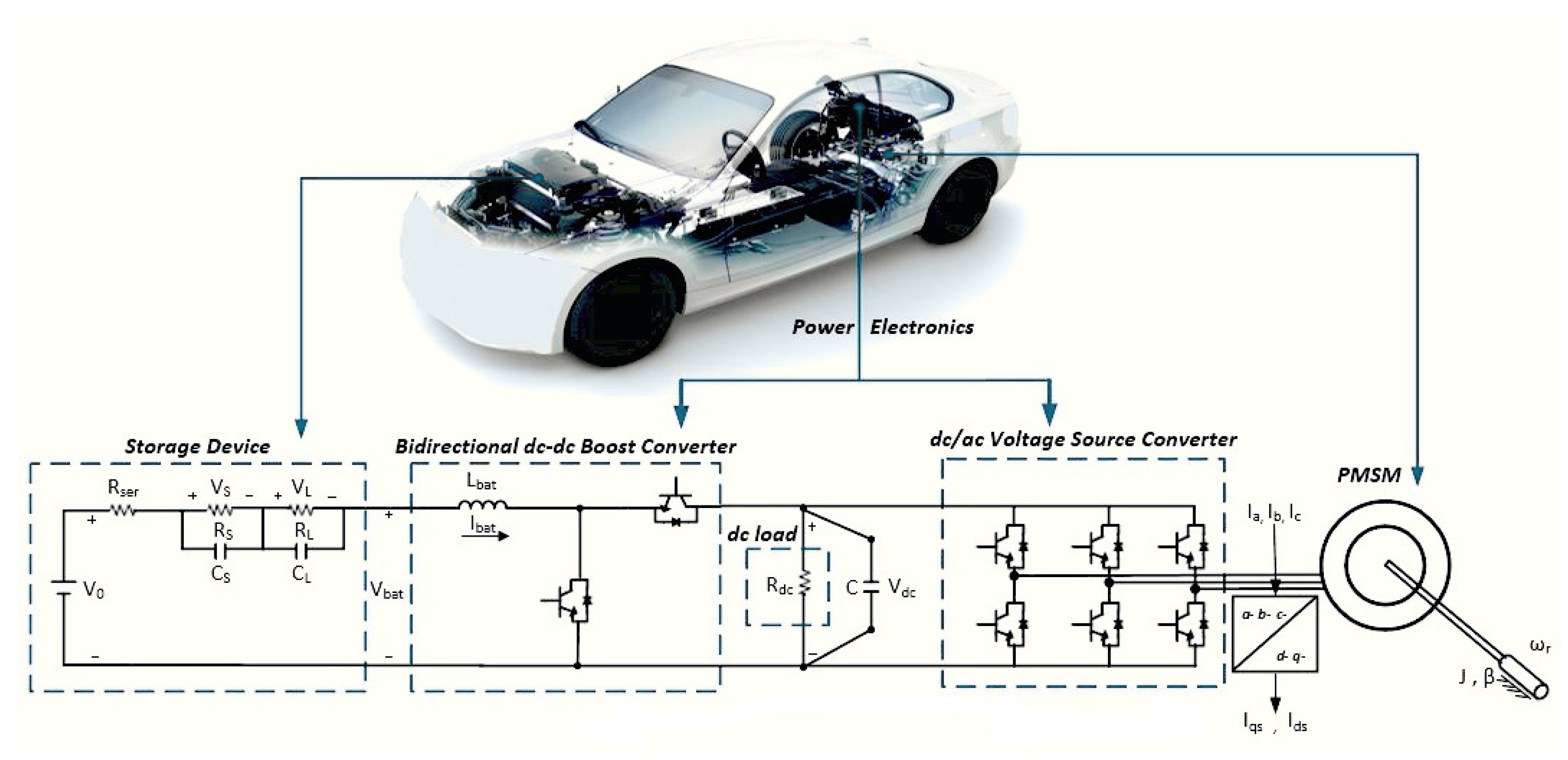
2. EV System Model
In modern EVs, the electromechanical structure is comprised of a power electronic converter, an electric machine, a mechanical transmission system and the driving wheels. The energy source involves the battery and an energy management converter, while the auxiliary subsystem consists of all the involved auxiliary DC loads (lights, climate system etc.) required in an EV [
9,
15].
In the present case, the most popular for EV applications Li-ion batteries are considered [
45] and a PMSM provides the needed torque on the car wheels. The power absorbed by the batteries or injected into the system is controlled by a DC/DC bidirectional boost converter, while the PMSM is driven through a three phase AC/DC voltage source converter [
43]. It is well-known that a DC/DC boost converter is usually employed in HEVs where a smaller battery pack is used. A DC/DC bidirectional boost converter can be used in EVs fed only by battery sources ([
11], Section 7.2 (§1.5)) in order to provide an additional controlled input that allows to exploit the AC/DC converter to operate the PMSM at maximum torque per ampere. Thus the DC/DC converter cost is compensated by optimizing the PMSM operation.
Figure 1 depicts the system under consideration.
The entire mathematical representation of the previously described EV system can be formulated as an Euler–Lagrange system, given below by Equation (1), wherein the equations of motion as well as the ones of the electric and electromagnetic part, are given in the
synchronously rotating reference frame [
37], for both the power converters and the PMSM. For the battery representation, electric circuit-based models are considered which are extremely useful for vehicle system level analysis [
11].
where
x represents the state vector and
m the controlled input vector and are provided respectively as
Matrix
M is a positive definite generalized inertia matrix,
is the Coriolis and centrifugal forces matrix, wherein the controlled input vector
m of the duty-ratio component signals is included,
D is the damping matrix, while
d represents the uncontrolled input vector that is considered as disturbance. All mentioned matrices are defined below.
where
,
are the
d- and
q-axis stator current components and
is the rotor mechanical angular velocity.
stands for the DC-link voltage,
stands for the output of the total battery array, and
and
are the internal battery short- and long-term voltage drops, respectively. Additionally, the control input of the battery-side boost converter is denoted by its duty-ratio
, while
and
represent the control inputs at the motor side, that actually stand for the
d- and
q-voltage source converter duty-ratio components. Also, in the disturbance vector, the external mechanical torque at the machine rotor is denoted by
and takes piecewise unknown constant values, while
stands for the battery internal voltage and is set to a known (based on battery specifications) constant value. It is mentioned that the electric equivalent circuit of the battery model incorporates the fundamental principles based on cell discharging data. Specifically, the differential equations for the voltage battery states
,
actually represent the voltage drops during diffusion- and stored-charge process, respectively. The voltage drop during diffusing charge process in a battery has the same form as that of a voltage across an RC circuit element and therefore is represented by a short time transient response (
for the short-term transient). On the other hand, the voltage drop during stored charge process in a battery has the form of a slowly decreasing response that represents the loss of batteries charge at rest and therefore describes a long-term transient (
for the long-term transient) ([
11], Section 4.5).
Table 1 provides the parameters of the system as they are used in simulation studies in
Section 6, while nomenclature is provided at the end of the paper.
The previous compact representation of the EV system will be the basis for the design of suitable controllers that guarantee asymptotic stability at the system desired equilibrium as will be discussed in the next sections.
3. Incremental Model
In the present work, the main objective is to perform the stability analysis of the closed-loop system, concerning a desired equilibrium at steady state, that generally differs from the origin by taking nonzero values. To describe the system dynamics around a nonzero equilibrium, one has to obtain the incremental model, with inputs, states and outputs to be the deviations from their steady-state equilibrium values, respectively [
39]. It is, therefore, essential to define, firstly, such a possible equilibrium.
Denoting the equilibrium by
wherein the elements
,
and
are predefined at their desired reference values, as implemented by the proposed in the next section control loops. In particular, we set (i)
, i.e., the current is considered zero in order to achieve optimal function of the EV motor, i.e., maximum torque per ampere (perpendicular rotor and stator fluxes), (ii)
, as it is manually provided by the car driver through the car pedals, in accordance to road and driving conditions and (iii)
be an arbitrary constant, adequate to support the converters duty-ratio operation under SPWM (Sinusoidal Pulse Width Modulation) [
37]. All the other five equilibrium values of
vector and the three equilibrium duty-ratio input components
result from setting to zero the derivatives of the 7th-order Equation (1) by considering constant and piecewise constant the disturbance components
and
, for this particular case, i.e.,
Combining Equations (1) and (2), the equation that describes the incremental model of the system is obtained as follows
where
is defined as the difference between the state vector and its equilibrium
.
Fortunately, the structure of matrix
allows, after some manipulations, the term
to be split and rearranged to
, where
is defined as the difference between the system controlled input vector and its equilibrium
, and wherein matrices
and
are provided as
Therefore, Equation (3) finally results in the following expression that describes the incremental model of the EV electromechanical system,
where
represents the state vector and
represents the input vector of the incremental model.
It is noticed that the incremental model has a substantially different structure from the initially used model given by Equation (1). In Equation (4) the external uncontrolled input vector does not exist while two new terms are appeared; a linear term with respect to , namely the , and a controlled input vector . It is worth noting that both matrices S and G are dependent from the particular equilibrium values.
Based on the extracted system incremental model three control schemes will be implemented, with each controlled input task corresponding to the desired response of the PMSM and the battery array.
4. The Proposed Control Scheme
The design and implementation of suitable control schemes that ensure an optimal and stable EV system operation, is of great importance. The most considerable control goals for an EV system include the operation of PMSM under optimal torque extraction, tracking of the motor and wheels speed at the reference value and recharging or discharging the battery under constant DC voltage. The main purpose of our design is to construct suitable control schemes satisfying the aforementioned tasks. Since the overall system stability is very significant for the security and reliability of an EV operation during a route, a rigorous method is developed, on the accurate nonlinear complete system model. On the other hand, the controllers have to be as simple as possible and for this reason the cascaded controller loops are selected. The cost of simplifying the controllers and using the cascaded scheme in guaranteeing stability, is the need of a complex and multi-step stability analysis, performed in contrary to the conventional heuristic design procedures used in such cases.
As previously discussed, the goal of the cascaded control is to improve the system performance regardless of the effect of the external disturbances. In our case, fast inner-loop current controller is used to compensate via the current variable the disturbance action very quickly, while the outer-loop controller eliminates the difference between the controlled current variable and its reference signal. The inner-loop controller is typically a P or a PI controller. The derivative action is usually not needed to speed up the loop, since the inner-loop controllers are selected to be adequately fast. Furthermore, in cases where the inner-loop reference value is not necessary to be exactly followed, the I-controller term is no longer needed. Adopting this general frame and defining in the EV system incremental model, the control input vector as
the following confined control schemes are proposed, one for each input. Therefore, as mentioned in the previous section, in order to achieve PMSM optimal (maximum torque per ampere) operation, it is essential to regulate the
d-axis current
to zero. To this end, the following classic PI controller is proposed, that actually provides the
d-axis duty-ratio input component
of the voltage source converter as
where the gains
and
are assumed positive constants,
represents the
d-axis current reference value and
is an arbitrary constant. Then, it is obvious that the
d-axis duty-ratio error component
of the voltage source converter is
since
under these circumstances.
Now, in order to track the reference speed provided by the car driver, a suitable speed PI controller, that makes use of the deviation between the rotor mechanical angular speed
and its corresponding to the equilibrium reference value
, is implemented. Specifically, the applied controller is described by
where
,
are positive constants.
The output
of controller in Equation (8) is used as the reference input of a faster inner-loop current controller which provides the
q-axis duty-ratio input component
of the voltage source converter. However, since the main control task at this loop is implemented by the external loop controller given by Equation (8), it is adequate to simplify the inner-loop current controller into a P controller. Thus, the duty-ratio input component
is realized by
where the gain
is a positive constant and
is arbitrarily chosen to a constant value.
As is evident, a proportional controller can only decrease and not eliminate the steady state error (no matter what is the magnitude of the selected proportional gain
). Therefore, the resulting
q-axis current equilibrium value
at the desired steady-state of the PMSM is slightly different from the reference value
used in Equation (9). Therefore, the related duty-ratio error component
is defined as
where it is determined:
.
In a similar manner, the controller that corresponds to the duty-ratio input
of the DC/DC boost converter is designed. Specifically, a PI controller that regulates the DC-link voltage
to a predefined reference value
, that corresponds to the equilibrium, is firstly implemented as follows
where the gains
,
are positive constants.
Again, the output of Equation (11) is not directly used to act on the boost converter duty-ratio input
, but stands as an intermediate reference value of an inner-loop P controller acting on the battery current
. The simple inner-loop P controller is thus chosen as
where gain
is a positive constant and
stands for arbitrarily chosen to a constant value.
Once again, it is obvious by Equation (12) that the desired
is finally obtained although
is generally different from
. Therefore, it is defined
where now,
.
5. Stability Analysis and Gain-Tuning of the Complete Controlled System
The proposed three controlled inputs
,
and
, are realized by a PI, P and P, respectively, fast inner-loop current controllers, while external slower PI outer-loop controllers are needed to drive the last two P inner-loop current controllers in a dual cascaded scheme. As the design of cascaded controllers is based on the time-scale separation principle [
39], the stability analysis presented in this section is divided into two separated parts. In the first part, the fast dynamics of the system are studied with the inner-loop fast dynamics included in the analysis. In the second part, we consider that the current loops transients are completed very fast and for this reason one can suppose, without significant error, that all currents are almost identical to their references, allowing us to take into account only the outer-loop slow controllers for the speed and the DC-voltage along with the mechanical and DC-voltage equations, respectively.
5.1. Stability Analysis with the Fast Current Controllers Dynamics Involved
To proceed with our analysis we first consider the inner-loop control inputs in Equation (5) of the incremental EV model by putting together Equations (7), (10) and (13)
where now the integral term dynamics of the first PI controller are expressed by the
state as
Substituting Equations (14) and (15) into Equation (4) and taking into account Equation (5), after some algebraic manipulations, the following closed-loop system representation is obtained
where the 8th-order state vector involves the integral term dynamics and is given by
.
The matrices appeared in (16) are given in the following, where it is considered
.
and
which are defined through the matrix
as follows
As a result, the closed-loop system representation with the fast inner-loop current controllers included is as follows
The incremental closed-loop model (17) is now examined for its stability by applying nonlinear Lyapunov-based techniques. To this end, we select the following Lyapunov function
Then, its derivative is calculated as follows
As previously determined, matrix
is antisymmetric and therefore the first term equals to zero, and therefore the derivative of the storage function finally results in
Matrix
in Equation (18) is an 8 × 8 symmetric matrix with its last column and last row to have all its elements equal to zero. Therefore, in order to ensure stability of the system in Equation (17),
has to be at most positive semidefinite, which simultaneously also means that the incremental model in Equation (17) represents an Euler–Lagrange system. To that end, it is sufficient, the 7 × 7 upper block matrix in
to be positive definite. Since this 7 × 7 matrix, denoted by
, can be written in the form
, where
A,
B and
C are determined as follows,
we can recall the relative theory on characterizing a symmetric positive definite matrix based on Schur complements [
46], which provides
Therefore, based on Sylvester’s criterion [
46], all leading principal minors of the matrix
should be positive. Taking into account that in our case
, we conclude the relations below that define the acceptable value regions for all the positive gains
, while the integral gain
can take any positive value.
As it is easily seen, all inequalities are independent of each other and therefore their solution becomes a simple algebraic problem after the substitution of the parameter and the reference signal values. It is noted that the first two inequalities may easily provide positive values for and , since both the values of the viscous friction coefficient b and the stators resistance are usually very small. Furthermore, the quadratic structure of the third inequality and the signs of the polynomial terms indicate that always a positive value for also exists.
Therefore, since
, the investigated equilibrium of
is globally stable and since
, then states
asymptotically tend to zero. Nevertheless, from the structure of the closed-loop system model (17) it is implied that
when
, the only equilibrium is
. Then we can apply the La Salle Invariance principle [
47]. In accordance to this principle, since
is a continuously differentiable, radially unbounded, positive definite function such that
and no other solution can stay identically in
than the trivial solution
, then the origin of system (17) is GAS. Consequently, the equilibrium
is GAS.
5.2. Stability Analysis with the Outer-Loop Controllers Involved
In order to complete our stability analysis it is essential to encompass the outer-loop controllers, as provided by Equations (8) and (11) which regulate and states, respectively, to their predefined reference values. Basing our cascaded control design on the time-scale separation principle we suppose that the outer-loop controller responses are much slower than the inner-loop ones. To this end, the differential equations that describe the response of the aforementioned states are taken into consideration, while the current loops dynamics are neglected and after applying Laplace transform, the transfer function of each subsystem is obtained. In a second stage, based on the classic feedback control theory, the closed-loop transfer functions that include the related PI outer-loop controllers are designed to achieve the desired settling time, by suitably tuning the gain values. In contrary, the current dynamics for and are not taken into account since these are considered fast enough and their corresponding values are assumed to follow directly the outer-loop controllers output commands: and , respectively.
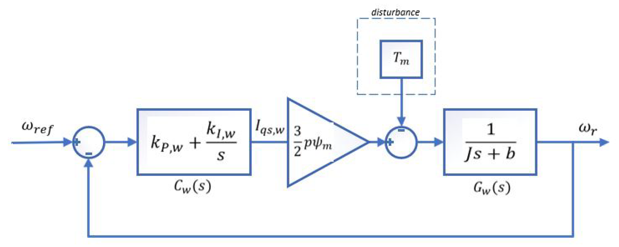
To be more specific, we firstly consider the controller in Equation (8) related to motor rotational speed
, which is provided by the third equation of (1),
Under the assumption that
reaches its reference value (which is equal to zero) very fast due to the action of the PI current controller installed for
and that the current
takes the value provided by the outer-loop PI speed controller, Equation (20) can be written as
Incorporating in the last equation the outer-loop controller in Equation (8), the slow dynamics of the system can represented by
Figure 2.
In the above mentioned expression (21) the last term is considered as disturbance and is omitted. Therefore, by applying Laplace transform on Equation (21), one obtains the following transfer function
while the transfer function
of the proposed PI controller is represented as
Then, the closed-loop system transfer function
is calculated as
Now selecting the PI controller gains
,
as follows
then, the closed-loop transfer function (22) becomes
It is easily observed that the motor rotational speed closed-loop transfer function results in a first order representation with arbitrary selected time constant . It is noted that both gains are functions of the system parameters and the desired time constant .
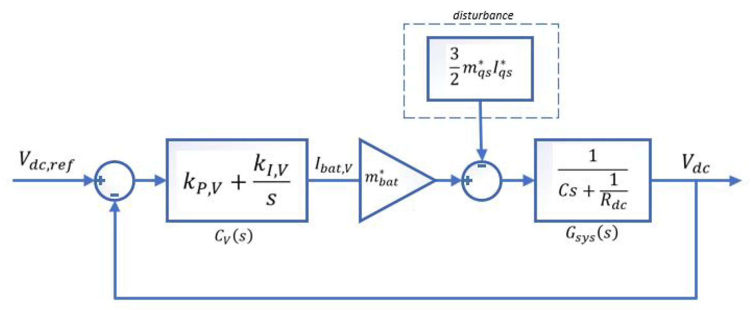
In a similar manner, the related to the DC-link voltage
outer-loop PI controller is analyzed and tuned. Again it is assumed that the current dynamics can be neglected. Starting from the
differential equation (actually the 7th Equation of (1))
Then, for the outer-loop slow system dynamics it is again assumed that
reaches its reference value which is equal to zero and
converges to its equilibrium. Therefore, the last equation can be written as
where
is provided by the outer-loop DC-voltage controller and
takes its steady-state constant value.
Figure 3 represents the closed-loop system with the slow outer-loop controller involved.
Following a similar procedure as for the motor speed controller gain tuning the resulting closed-loop system transfer function
is provided now as follows
Once again selecting the PI controller gains
,
as follows
then, the closed-loop transfer function (24) becomes
It is easily observed that the DC-voltage closed-loop transfer function results in a first order representation with arbitrary selected time constant . It is noted that both gains are functions of the system parameters and the desired time constant . Also, the design is dependent from which takes values in the interval , and it is pre-estimated by the designer.
From the closed-loop transfer functions (23) and (25), it is proved that the dominant system response of the speed and DC-voltage states is asymptotically stable with a time constant selected by the designer. It is evident that the inner-loop system stability is a pre-requirement for the stability of the outer-loop controllers.
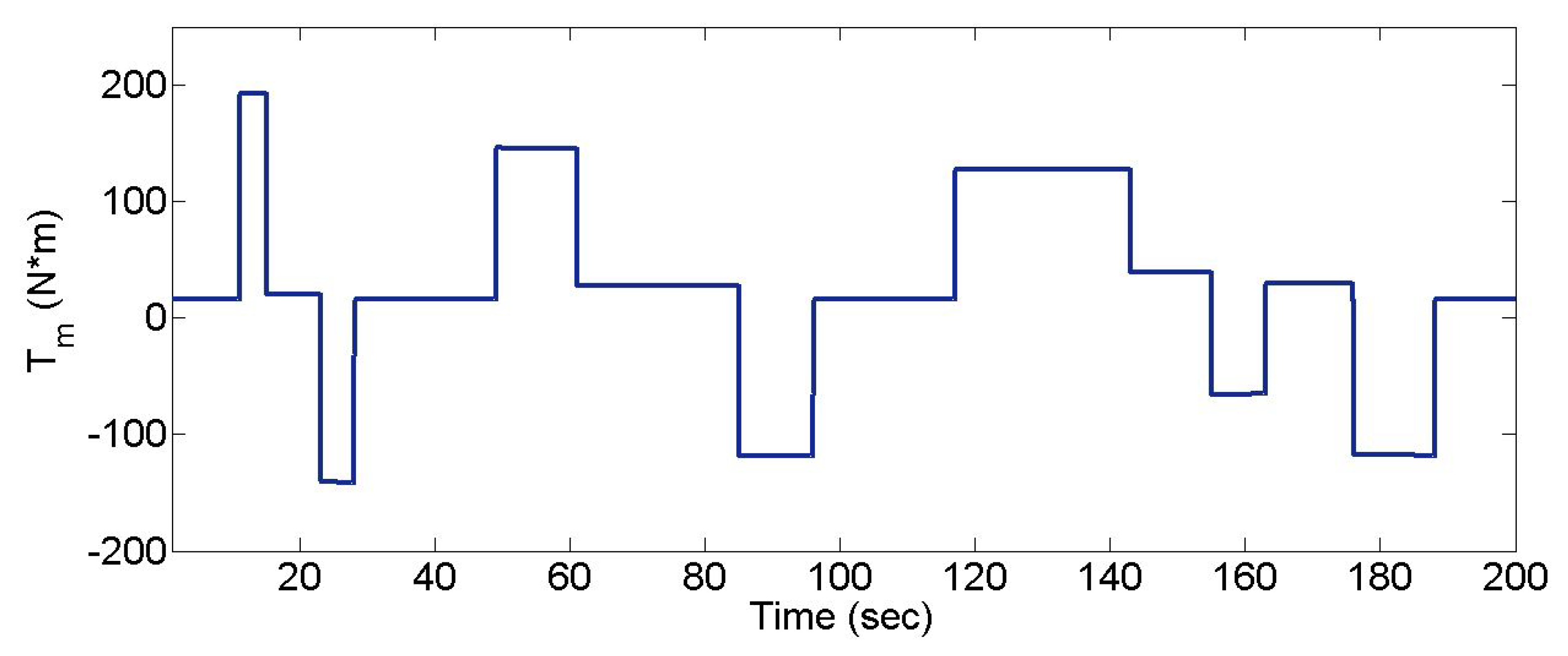
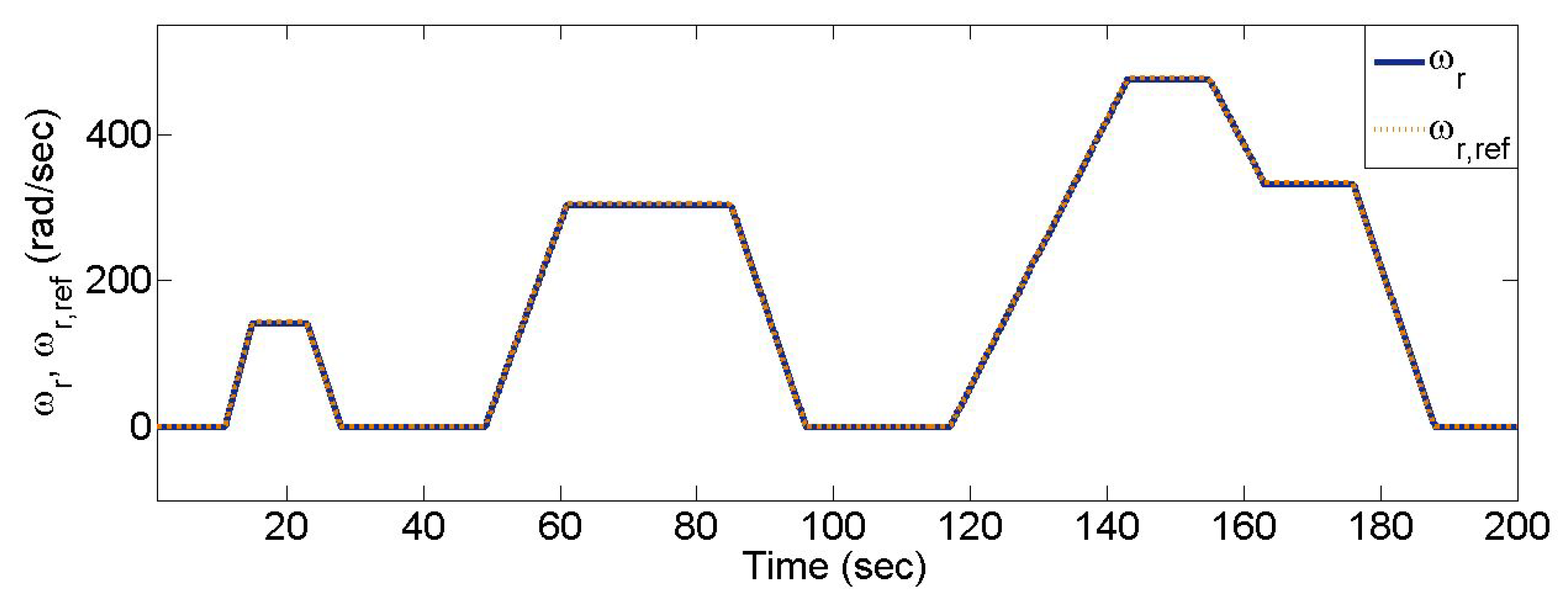
6. System Examination and Results
A detailed design of the three cascaded controller loops was implemented and examined through simulations on a Simulink environment deployed exclusively for the entire EV electromechanical and controller scheme. It did not used any of the existing Simulink/Matlab standard blocks for the power converters, for the PMSM, etc. All the components and system parts have been accurately implemented by their mathematical models. Parameters for all the several EV subsystems are summarized in
Table 1, while all controller gains were chosen in accordance to the stability analysis presented in the previous section. The simulated operation mode of the PMSM was based on the new European driving cycle (NEDC), often used as a typical profile for the EV velocity [
48] in optimization studies. In the present case, however, our intention is to indicate the good transient and steady state performance of the proposed controller. Therefore only a small part of the NEDC cycle was selected, actually the one corresponding to the urban driving cycle (UDC) that involves adequate speed and torque changes for the evaluation of the dynamic response. The mechanical torque
during the selected route was calculated in a standard manner by using the car force model that takes into account the gravitational, rolling resistance, wind and inertial forces. The analytic expressions are thoroughly described in bibliography [
11]. Similarly, the PMSM speed command input profile of
resulted directly from the used UDC velocity profile via a constant transformation depending on the characteristics of the vehicle mechanical transmission system. In accordance to the UDC modeling and the car force model the different constant levels of the external torque
as well as its changing rates are depicted in
Figure 4.
Figure 5 provides the mechanical angular velocity
, which clearly tracks its reference value
, without observable overshoots or oscillations, while in
Figure 6, the regulation of the DC-link voltage to its constant reference value
V is depicted. Both responses satisfied the outer-loop controllers tasks since they follow very close the reference inputs. It is remarkable to note that rather large changes of torque result in very smooth responses.
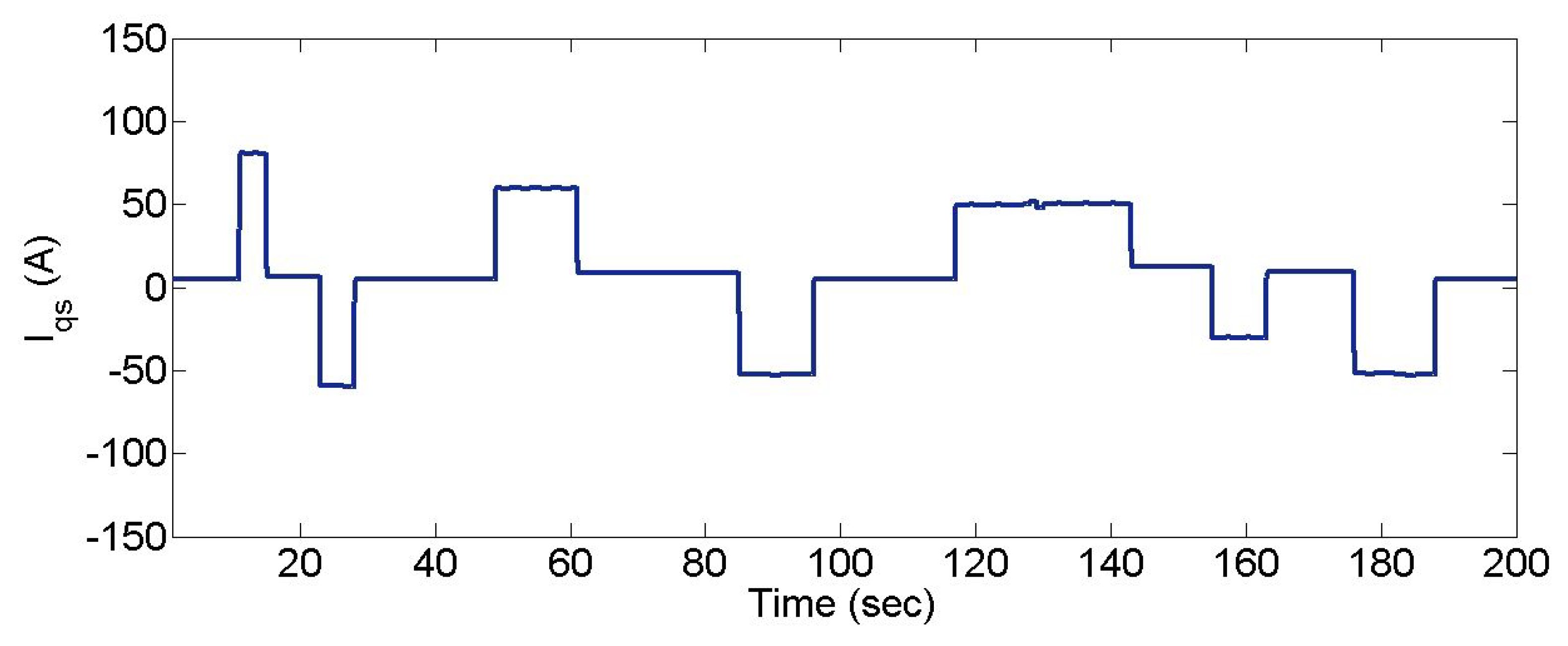
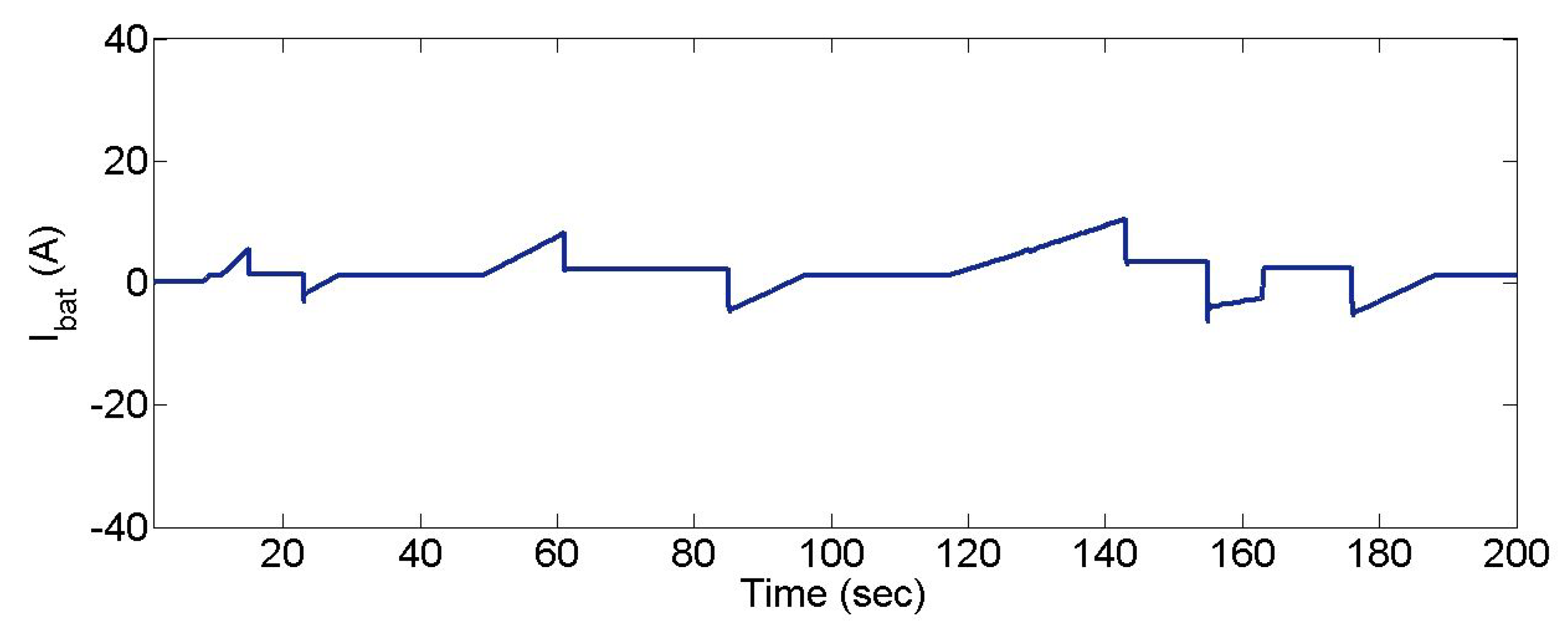
The inner-loop control responses are evaluated through the responses of the currents shown in
Figure 7,
Figure 8 and
Figure 9. Particularly, in
Figure 7 which represents the
d-axis current, it is shown that the current converges very fast to the reference value
, satisfying one of the main control goals, i.e., the PMSM optimal torque operation. In
Figure 8 it is indicated that the
q-axis current response follows the torque variations. The battery current
, indicated in
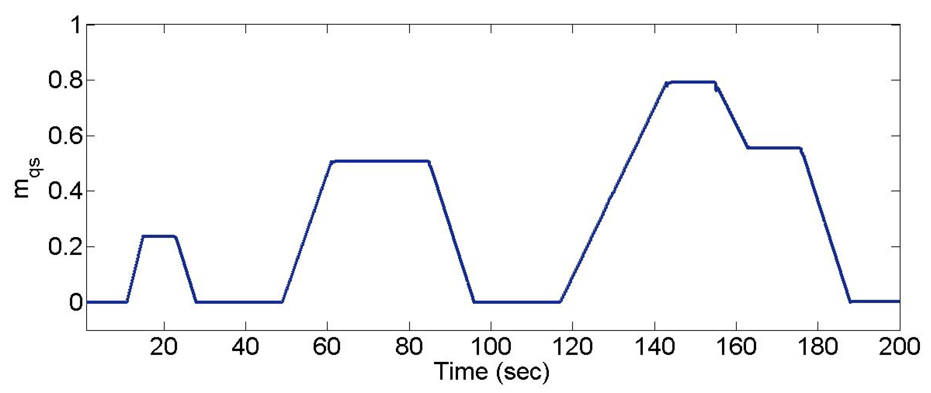
Figure 9, suitably responds to provide the necessary power to/from the battery by injecting/extracting current in accordance to the unknown external torque profile. The duty-ratio
d- and
q-axis input components
and
of the voltage source converter as these are realized by the proposed control scheme are presented in
Figure 10 and
Figure 11, respectively. Their values were inside the acceptable ranges and as shown in
Figure 10 the
d-component duty-ratio takes on positive or negative values (also the
q-component duty-ratio can take positive or negative values) while the duty-ratio of the voltage source converter obviously takes only positive values since it is calculated through
. Finally,
Figure 12 indicates the duty-ratio input signal
of the DC/DC boost converter with its values to be positive between 0 to 1. All the three duty-ratio input signals have a very satisfactory form and effectively drive the whole system to the stable equilibria without significant overshoots or oscillations. In all the simulated cases, the desired operating conditions are achieved in a smooth and stable manner.
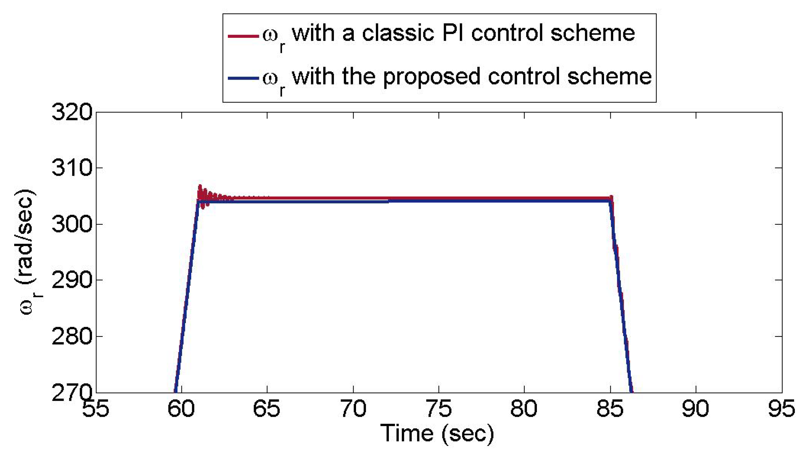
To further evaluate the very good system performance, a comparison of the proposed approach with the commonly used on both the Li-ion battery and the PMSM converter power interfaces conventional PI/PI cascaded control schemes are examined ([
49], Chapter 14). In
Figure 13 and
Figure 14 the DC-link voltage
and motor speed
are presented for both cases. In order to have better comparisons we focus on a limited duration between 55 and 95 s. One can easily see the superiority of the proposed controllers since overshoots and oscillations are observed when the conventional controllers are applied. This is an expected result, known in the literature [
49], while the improvement of the proposed approach is due to the fact it provides a complete design tool that enables effective gain tuning for both the inner- and outer-loop controllers. It is worth noting that since the motor speed directly impacts on the vehicle velocity response, even a small speed overshoot (or oscillation) is clearly inconvenient for the EV passengers and therefore this point constitutes a critical design parameter.


