Article

Modeling and Mechanism Investigation of Inertia and Damping Issues for Grid-Tied PV Generation Systems with Droop Control

1
School of Electrical and Control Engineering, Shaanxi University of Science & Technology, Xi’an 710021, China
2
School of Electrical and Information Engineering, Hunan University of Technology, Zhuzhou 412008, China
3
Department of Electrical Engineering, Hong Kong Polytechnic University, Hong Kong 999077, China
4
School of Automation, Nanjing Institute of Technology, Nanjing 211167, China
*
Author to whom correspondence should be addressed.
Energies 2019, 12(10), 1985; https://doi.org/10.3390/en12101985
Submission received: 23 April 2019 / Revised: 17 May 2019 / Accepted: 20 May 2019 / Published: 23 May 2019
(This article belongs to the Section A2: Solar Energy and Photovoltaic Systems)

Abstract

:
Inertia effect and damping capacity, which are the basic characteristics of traditional power systems, are critical to grid frequency stability. However, the inertia and damping characteristics of grid-tied photovoltaic generation systems (GPVGS), which may affect the frequency stability of the grid with high proportional GPVGS, are not yet clear. Therefore, this paper takes the GPVGS based on droop control as the research object. Focusing on the DC voltage control (DVC) timescale dynamics, the mathematical model of the GPVGS is firstly established. Secondly, the electrical torque analysis method is used to analyze the influence law of inertia, damping and synchronization characteristics from the physical mechanism perspective. The research finds that the equivalent inertia, damping and synchronization coefficient of the system are determined by the control parameters, structural parameters and steady-state operating point parameters. Changing the control parameters is the simplest and most flexible way to influence the inertia, damping and synchronization ability of the system. The system inertia is influenced by the DC voltage outer loop proportional coefficient Kp and enhanced with the increase of Kp. The damping characteristic of the system is affected by the droop coefficient Dp and weakened with the increase of Dp. The synchronization effect is only controlled by DC voltage outer loop integral coefficient Ki and enhanced with the increase of Ki. In addition, the system dynamic is also affected by the structural parameters such as line impedance X, DC bus capacitance C, and steady-state operating point parameters such as the AC or DC bus voltage level of the system and steady-state operating power (power angle). Finally, the correctness of the above analysis are verified by the simulation and experimental results.

1. Introduction

In recent years, with the increasingly serious problems of energy crisis and environmental pollution, the need for development of green and clean energy sources has become the consensus of the world [1,2,3]. Among them, photovoltaic power generation, as one of the most promising power generation technologies, has been widely considered [4].
However, with the increasing penetration of photovoltaic (PV) in the public power grid, large-scale grid-tied PV inverters featuring low inertia and weak damping are being connected to the power system, which brings severe challenges to the safe and stable operation of the power grid [5,6]. Electric vehicles and distributed energy storage are becoming more and more popular. The source and load boundary of the power grid is more blurred, and there is great uncertainty, which makes the “operation mode” of the power system more diversified, decentralized and differentiated [7]. In the future, renewable energy will need to take responsibility for part of the load balance. At the same time, how to evaluate the inertia, damping and synchronization level of the GPVGS under typical control strategy so as to realize the friendly and compatible connection of renewable energy to the power grid has become an urgent problem to be solved [8].
In view of the inertia and damping mechanism research of renewable energy grid-tied power generation system, reference [9] makes full use of the idea of multi-time scale, grasps the time scale of interest, ignores other dynamic processes, and establishes the mathematical model of the system. Reference [10] divides the dynamic behavior of power electronic grid into three timescale: AC current, DC voltage and mechanical speed. Among them, the inertia characteristic is mainly affected by the DVC timescale dynamic process, so the inertia characteristic of the converter system is mainly to analyze the dynamic process of the DVC timescale.
There are few studies on the inertia, damping and synchronization characteristics of the GPVGS at home and abroad. Reference [11] used virtual synchronous generator (VSG) technology to simulate the characteristics of traditional synchronous machines and improve the standby rotational inertia of the GPVGS. References [12,13] proposed a reactive standby PV-VSG strategy for variable step power tracking to provide inertia and damping support for the PV system. References [11,12,13] only made the system have certain inertia and damping characteristics from the perspective of the control method, and did not analyze the inertia and damping mechanism affecting the system from the physical mechanism level. In [14], the electric torque analysis method is used to analyze the inertia and damping characteristics of the grid-tied inverter itself, but the influence of the primary side energy was not considered. References [15,16] combined with energy storage devices to analyze the effects of two different control strategies on the inertia and damping characteristics of grid-tied energy storage systems. Based on [11,12,13,14,15,16], we want to obtain a similar inertia expression (1) for PV systems compared to conventional synchronous generator:
J = 2 H = 4 π 3 f G D 2 S N ( n 60 ) 2 ,
where J represents the inertia; f is the power frequency; G is the gravitational acceleration; D is the diameter of the object; SN is the rated system capacity; n is the speed of synchronous generator.
This paper establishes the DVC timescale mathematical model of the GPVGS based on droop control, and uses the electric torque method to reveal the factors and action rules that affect the inertia, damping and synchronization ability of the system from the physical mechanism perspective. It is beneficial to select appropriate control strategies and parameters, so that the GPVGS presents better inertia, damping and synchronization characteristics, to improve the stability of the power system.

2. Research Ideas and Methods

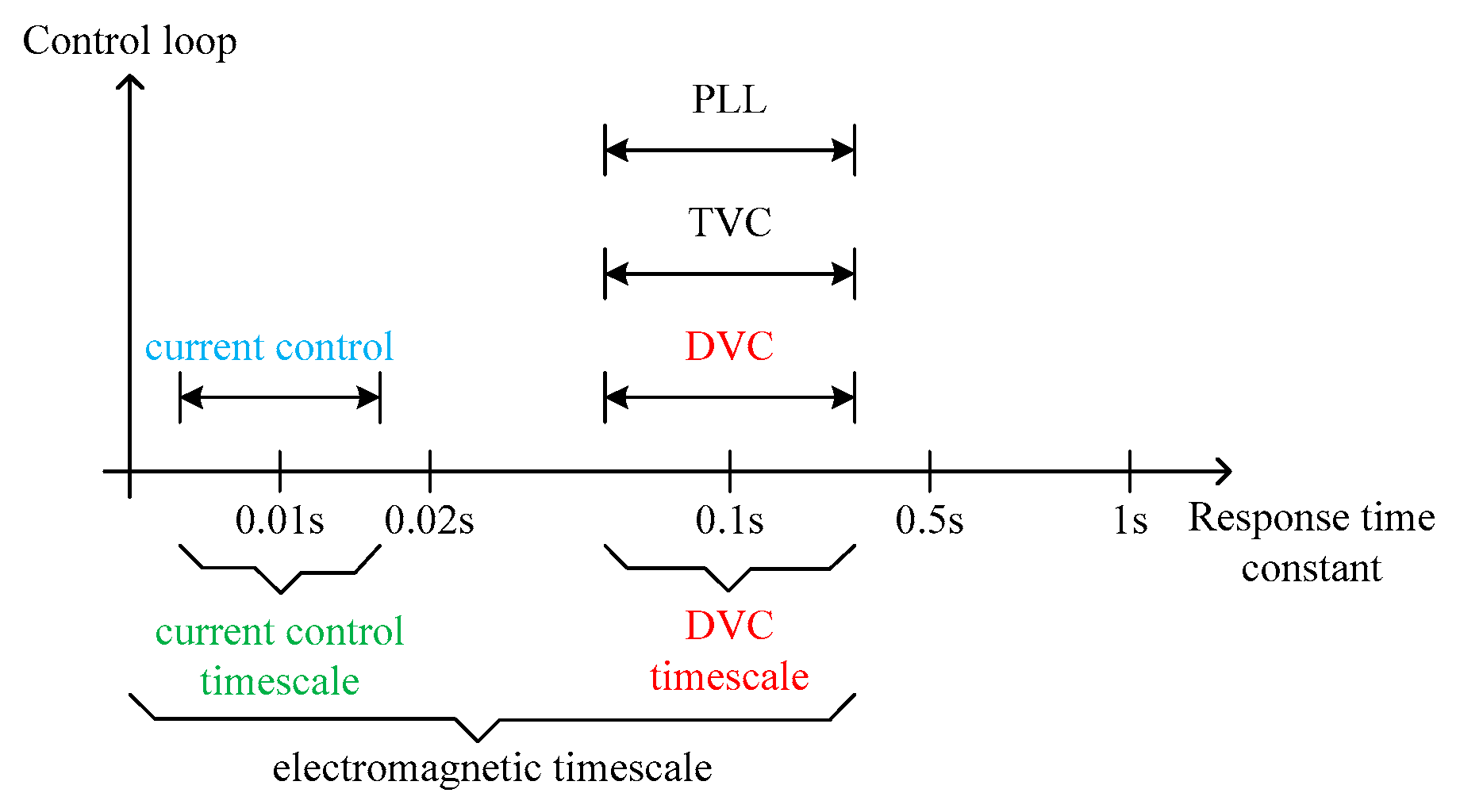
2.1. Definition of DVC Timescale in the GPVGS

As we know, the response time constant of current control is often designed around 10 ms (which is closely related with the switching frequency), and those of DVC and PLL about ten times larger are selected [17]. Further considering the different response speeds of these control loops, the reference [10] extends VSC electromagnetic dynamics into two types, viz., dynamics in current control timescale (around 10 ms) and dynamics in DVC timescale (around 100 ms), as illustrated in Figure 1. For simplicity, dynamics in these two timescales can be analyzed individually, due to their relatively separated response times. Therefore, for DVC timescale dynamic analysis, AC or DC currents timescale dynamic can be considered to instantaneously track their reference values.

2.2. Electrical Torque Analysis Method

From the aspects of physical structure, characteristic parameters, physical mechanism and dynamic model of energy transfer process, there is a significant correspondence between the traditional RSG and the new energy grid-tied power generation system. There is a strong similarity among the structure, motion mechanism and mathematical model of system. Therefore, we can learn from classical electric torque analysis method to analyze the influencing factors and action laws affecting the stability of the GPVGS from the physical mechanism perspective [18].
Analogous to the small-signal stability method of the traditional RSG, the DVC timescale dynamic process of the GPVGS can be expressed by the incremental equation [14]:
{ d Δ δ d t = Δ ω 2 H d Δ U dc dt = Δ P in Δ P e ,
where H = C U dc 2 2 S B is the inertia time constant of the system.
In order to analyze the inertia, damping and synchronization characteristics of the grid-tied inverter system, the static synchronous generator (SSG) model is proposed in literature [14]. The DVC timescale dynamic process of the grid-tied inverter is described by the following standard equation:
{ d Δ δ d t = Δ ω T J d Δ ω dt = T D Δ ω T S Δ δ ,
where TJ, TD, and TS represent the equivalent inertia, damping, and synchronization coefficient of the SSG, respectively.
The above three parameters are important physical concepts for characterizing the dynamic characteristics of SSG in classical stability theory. The electric torque analysis method based on the above concept can analyze the system stability from the physical mechanism perspective. And TJ, TD and TS respectively represent inertia level, damping and synchronization capability of the grid-tied inverter system [14].

3. The Control Strategy of System

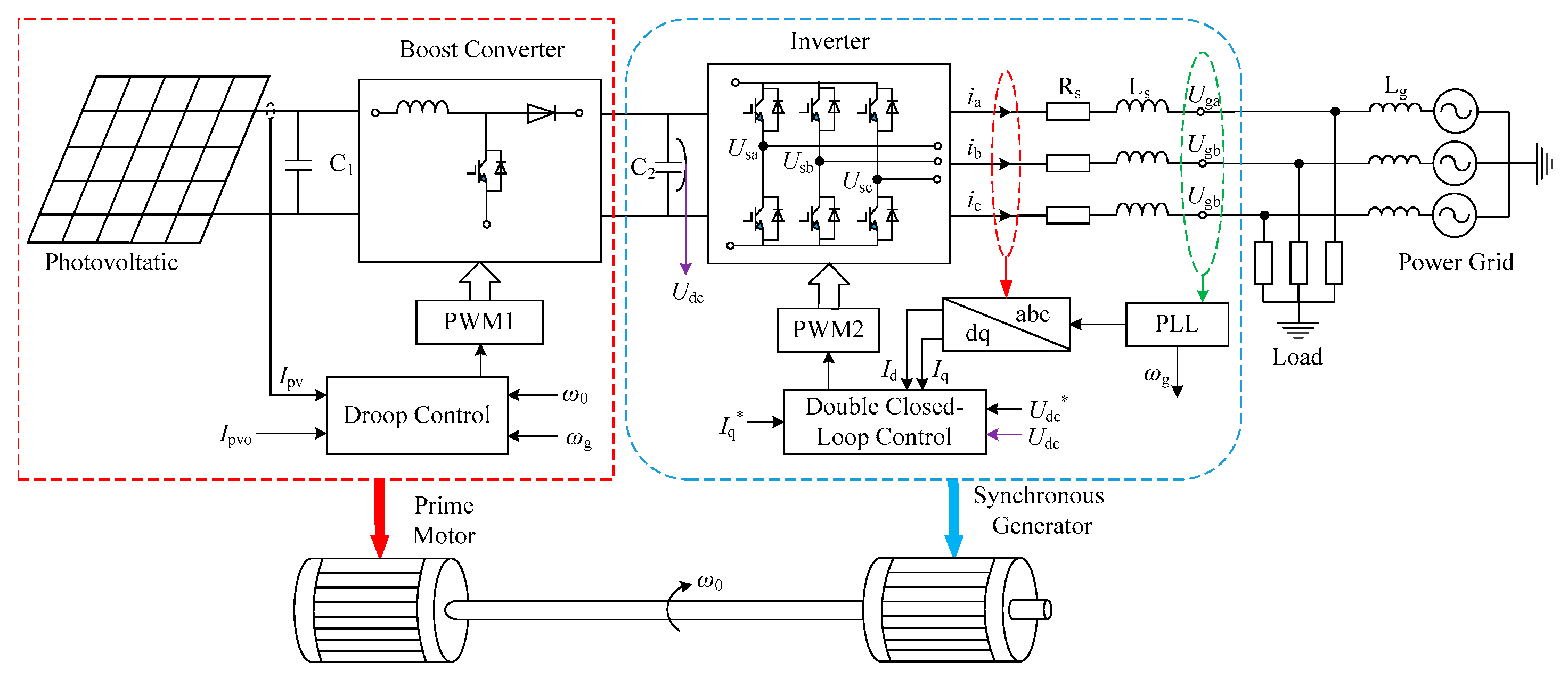
3.1. System Description

The main circuit topology and control method of the GPVGS based on droop control is shown in Figure 2. This system consists of a photovoltaic array (PVA), boost converter, and inverter. The boost converter adopts the frequency droop control to simulate the primary frequency modulation process of the prime mover. The inverter adopts the double closed-loop control of the conventional voltage and current to correspond to the rotational synchronous generator (RSG). This control strategy can simulate the traditional peak-regulation power plant when a large proportion of renewable energy is connected to the grid, so that the GPVGS is responsible for the load balancing.
In order to better make the GPVGS respond to the load balancing responsibility, when the power grid fluctuates, the system provides reasonable inertia and damping support, so that the system can reach the power balance as soon as possible. When the maximum output power of the PV is much larger than the system’s load power or scheduling demand of power grid, the boost converter adopts the deloading maximum power point tracking (DMPPT) control method and works in the droop control mode to meet the supply and demand balance. When the PV output power is much smaller than the load power or scheduling requirements of power grid, the boost converter can only maintain system stability with the maximum power output.
The characteristic curve of PV-PU is shown in Figure 3. When the power frequency droop control is performed, it can be seen from the PV curve that one power command P1,2 at any time corresponds to the output voltages U1 and U2 of the two PV panels. However, each terminal voltage has a one-to-one correspondence with power. Therefore, the power frequency droop control can be improved to the frequency droop control. The frequency droop is used to control the PVA output voltage as the outer loop, and the PVA output current is used as the inner loop.
Taking the maximum power point of the P-U curve as the boundary, the interval (0, Ump) and (Ump, Uoc) are opposite to the monotonicity of the power. In the interval (0, Umpp), the output voltage Upv of PVA is positively correlated with the output power Ppv, and is limited by the minimum voltage UDCmin of the DC-side inverter failure. Meanwhile, the adjustable power is limited and the adjustment speed is slow. In the interval (Ump, Uoc), Upv is negatively correlated with Ppv. Ppv can be adjusted in a full range. The system sensitivity is good due to the large slope. In order to ensure the safe and stable operation of the GPVGS with operating at a faster adjustment speed in the full power range, (Ump, Uoc) is selected as the operating range of the PVA output voltage.
In order to simplify the modeling, according to the U-I curve shown in Figure 4, the output terminal voltage Upv and current Ipv of the PVA under the voltage frequency droop control have the problem of repeated control. Upv is multiplied by Ipv to determine the output power Ppv. To do this, you only need to select one of the variables between Upv and Ipv for control. The frequency droop can be used to control Ipv, to indirectly control Ppv. In order to ensure the stability, speed and full power range of the GPVGS to respond to load balance, this paper takes the interval (0, Imp) as an example for related research.
In this paper, a 10-string and 5-parallel Suntech Power STP200-18-UB-1 is used to form PVA, whose U-I characteristic curve is consistent with Figure 4 at a specific illumination and temperature. The electrical parameters of the PVA under standard conditions are shown in Table 1:
Reference [19] has proved that the mathematical model of PVA can be linearized. So this approximation method is used in this paper. In the interval (0, Imp), the U-I curve shown in Figure 3 can be simplified by a straight line equation. The simplified expression is:
I pv = K pv ( U pv U oc ) ,
where Kpv is the simplified slope of the U-I curve of Ipv ϵ (0, Imp).
The voltage and current output of the PV are linearized as:
Δ U pv = 1 K pv Δ I pv ,

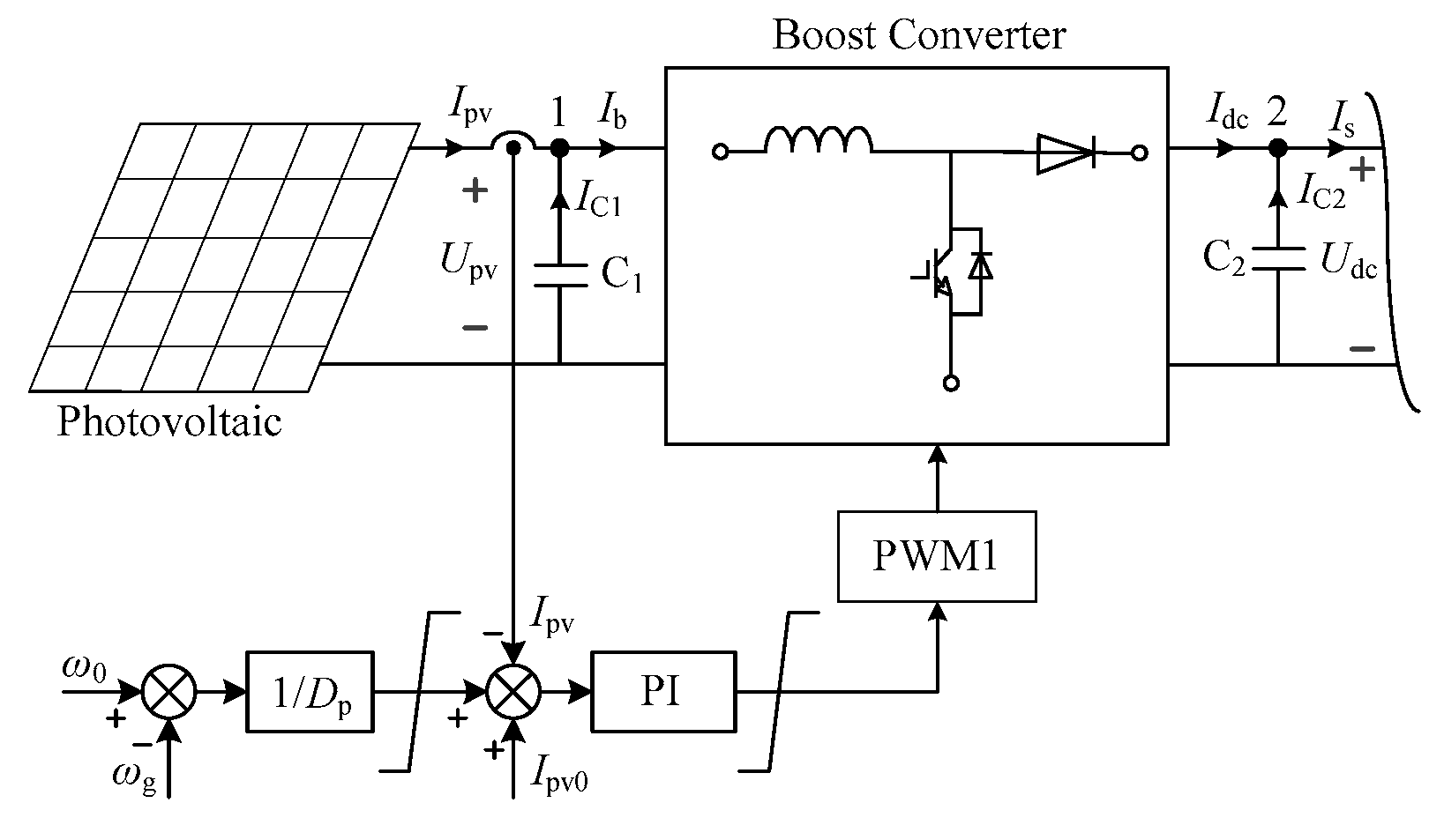
3.2. The Control Strategy of Boost Converter

Considering the above factors of the PVA, the control strategy of the PVA and the boost converter is shown in Figure 5. The control strategy is used the frequency droop as the outer ring, and the output current of the PVA as the inner ring. The frequency droop is used to control the output current of the PVA, and indirectly control the output power of the PVA.
In the double closed-loop control strategy of frequency and current shown in Figure 5, the bandwidth of the general inner loop is much larger than the outer loop. That is to say, for the frequency control process of the outer loop, the current control timescale dynamic process of the inner loop can be ignored [20]. For the DVC timescale dynamic process, the current output of boost convert can be expressed as:
I pv * = I pv = 1 D p ( ω 0 ω g ) + I pv 0 ,
where Dp is the droop coefficient, ω0 is the angular frequency set by the system, ωg is the angular frequency of the real-time detection of the grid, Ipv0 is the steady-state operating point of the system, and Ipv0 ϵ (0, Imp).
Equation (6) is linearized and can be expressed as:
Δ I pv = 1 D p Δ ω ,
For power node 1, capacitance C1 is similar to LCL filter, and its dynamic response speed is very fast [18]. It belongs to the current control timescale category, and its dynamic process can be ignored, namely:
I pv I b ,
For the boost converter, ignoring its own loss, the power both before and after the converter is considered to be constant, i.e.:
P in = U pv I pv = U dc I dc ,
For small-signal stability analysis, the incremental relationship among variables is generally considered. Therefore, after linearizing Equation (9), you can get:
Δ P in = Δ U pv I pv 0 + U pv 0 Δ I pv = Δ U dc I dc 0 + U dc 0 Δ I dc ,
where Upv0 and Ipv0 are the steady-state operating point parameters of the PV.
Substituting Equations (5) and (7) into (10), the output power of the boost converter can be linearized as:
Δ P in =   ( 1 K pv I pv 0 U pv 0 ) 1 D p Δ ω ,

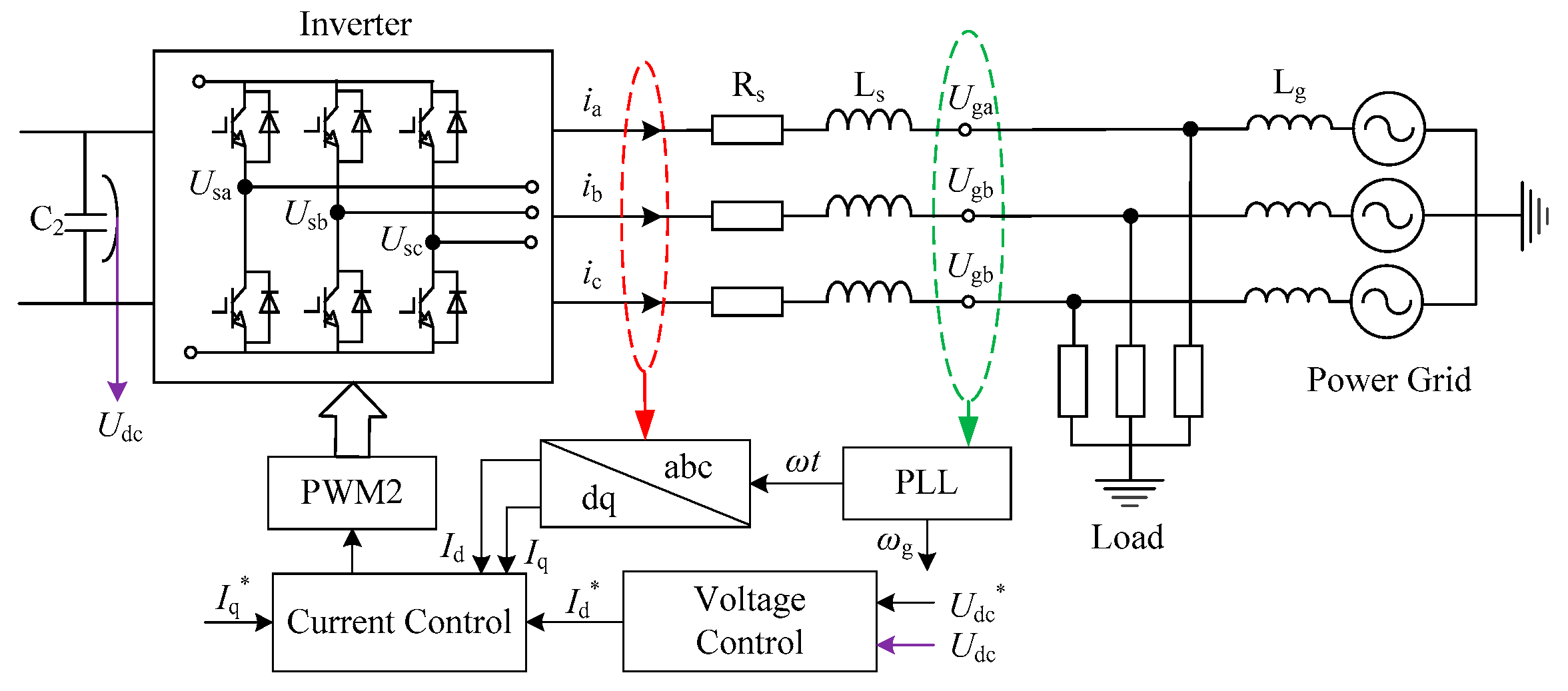
3.3. The Control Strategy of Grid-Connected Inverter

As shown in Figure 6, the grid-tied inverter adopts double closed-loop control strategy of DC voltage outer loop and current inner loop. The DC voltage outer loop is based on the principle of power balance to realize the voltage regulation control of the DC bus. The current loop mainly realizes the tracking control of the grid side current to realize the sine wave current control of the unit power factor of the grid-connected inverter. At the same time, the grid-tied current is limited to ensure the safe operation of the grid-tied inverter. In the topology of the L-type grid-tied inverter, Rs and Ls respectively represent the equivalent series resistance and inductance of the L-type passive filter and the grid-tied inverter. And Lg represents the equivalent reactance between the grid-tied inverter and the infinite grid. Lg also represents the strength of the electrical connection between the grid-tied inverter and the infinite grid [21].
A simplified analysis of the main circuit of the grid-tied inverter is shown in Figure 7. Us is the excitation potential amplitude of the grid-tied inverter, corresponding to the fundamental component of the outlet voltage before the filter of the grid-tied inverter. δ is the phase angle difference between the grid-tied inverter and the grid terminal voltage. Ug is the amplitude of the grid-tied inverter, which corresponds to the terminal voltage of the grid.
In the modeling and analysis of grid-tied inverter, a synchronous rotating coordinate system based on grid voltage vector orientation, is often used to make the grid voltage vector Ug coincide with the d-axis of the synchronous rotating coordinate system [22], as shown in Figure 8. The excitation potential amplitude Us of the grid-tied inverter rotates at a synchronous angular frequency ω0. The grid terminal voltage Ug is rotated according to the angular frequency ωg with reference to the d-axis. ϕ is the phase difference angle between the terminal voltage and output current of the grid-tied inverter. Φ is the phase angle difference between the excitation potential of the grid-tied inverter and the output current.
According to Figure 8, the active power Pe of the grid-tied inverter is:
P e = 3 2 U s U g X sin δ ,
where: the structural parameter Xω0L.
In the grid-tied inverter part, the conventional double closed loop control strategy is adopted. The DVC timescale modeling analysis method can also be adopted. The dynamic process of the current inner loop is ignored, and only the control process of the DC voltage outer loop is considered [23]. In this paper, only the active power part of the GPVGS is analyzed. Therefore, in the control block diagram of Figure 6, the reactive current reference Iq* is set to 0, and the dynamic process of the active current Id can be expressed as:
I d * = I d = ( K p + K i s ) ( U dc * U dc ) ,
where Kp and Ki are the PI parameters of the DC voltage outer loop.

4. Dynamic Characteristics Analysis of the GPVGS

4.1. SSG Model of the GPVGS

In order to study the inertia, damping and synchronization characteristics of the GPVGS, the above research method are used as the theoretical basis to establish the SSG model of the GPVGS based on droop control.
Firstly, from the phasor diagram illustrated in Figure 8, it is easy to get:
I d = U s X sin δ ,
Combining Equations (13) and (14), we can get:
U s X sin δ = ( K p + K i s ) ( U dc * U dc ) ,
For the small-signal stability analysis, linearizing Equation (15) to obtain:
s K Δ δ = ( s K p + K i ) Δ U dc ,
where K = U s X cos δ 0 , which is determined by the structural parameter and the steady-state operating point parameters of the system.
Linearizing Equation (12), it can be expressed as:
Δ P e = 3 2 K U g Δ δ ,
This paper not only analyzes the DVC timescale dynamic process of the grid-tied inverter, but also considers the dynamic effects of the PVA and the boost converter. Substituting Equations (11), (16) and (17) into (2), the SSG model of the GPVGS based on droop control is:
{ d Δ δ d t = Δ ω ( 2 K H + ( U pv 0 1 K pv I pv 0 ) K p D p ) d Δ ω d t = ( 3 2 K K p U g + ( U pv 0 1 K pv I pv 0 ) K i D p ) Δ ω 3 2 K K i U g Δ δ ,
Comparing Equation (18) with (3), the equivalent inertia coefficient TJ, the equivalent damping coefficient TD and the equivalent synchronization coefficient TS of the GPVGS based on droop control are respectively expressed as:
{ T J = 2 K H + ( U pv 0 1 K pv I pv 0 ) K p D p = 2 C U s U dc 2 S B X cos δ 0 + ( U pv 0 1 K pv I pv 0 ) K p D p T D = 3 2 K K p U g + ( U pv 0 1 K pv I pv 0 ) K i D p = 3 2 U s U g X K p cos δ 0 + ( U pv 0 1 K pv I pv 0 ) K i D p T S = 3 2 K K i U g = 3 2 U s U g X K i cos δ 0 ,

4.2. The Physical law of the System Dynamic Characteristics

According to Equation (19), the inertia, damping and synchronization characteristics of the GPVGS based on droop control are not only affected by the control parameters of the system, but also influenced by the structural parameters and the steady-state operating point parameters of the system.

4.2.1. Influence of Control Parameters

From the perspective of system control parameters, TJ is affected by the droop coefficient Dp and the proportional coefficient Kp of the DC voltage outer loop PI controller. With the decrease of Dp, the stronger of the coupling between the output power of the boost converter and the system frequency. The greater the output power, the stronger the power support effect on the system, and the inertia effect of the system is enhanced. With the decrease of Kp, the weaker of the inertia effect exhibited by the system.
TD is related to the PI parameter of the DC voltage outer loop and Dp. The damping characteristic is positively correlated with the PI parameter of the DC voltage outer loop. That is to say, with the increase of PI parameter, the system of stability speed and quasi-degree are obviously accelerated to maintain the DC bus voltage. The damping effect of the system is enhanced. The damping characteristic is negatively correlated with Dp. Namely, with the decrease of Dp, the damping effect of the system is stronger.
TS is only affected by the integral coefficient Ki of the DC voltage outer loop PI controller. The synchronization characteristic is positively correlated with Ki. With the increase of Ki, the synchronization effect of the system is stronger.

4.2.2. Influence of Structural Parameters

From the perspective of system structural parameters, TJ, TD and TS are related to structural parameter X. With the decrease of X, the closer the electrical distance between the system and the infinite grid, the stronger the coupling degree of the large grid, the greater the inertia, damping and synchronization capability of the system. Therefore, the inertia, damping and synchronization characteristics of the system can be improved by reducing the line impedance X or reducing the installation distance from the large power grid.
The DC bus capacitor C is related to TJ. With the increase of C, the more energy is stored or released, the stronger the ability to suppress interference, which means that the system inertia is stronger. Therefore, the system inertia can be improved by increasing C [24].

4.2.3. Influence of Steady-State Operating Point Parameters

From the perspective of the steady-state operating point parameters of the system, TJ is related to Udc. With the increase of Udc, the system’s inertia is enhanced. This is because the higher voltage, the more energy storage capacity, and the stronger the ability to suppress external interference. Ug affects the damping and synchronization effects of the system. With the increase of Ug, the damping and synchronization ability of the system is enhanced. The steady-state operating point parameters Us and δ0 simultaneously affect the inertia, damping and synchronization characteristics of the system. Increasing Us can simultaneously improve the inertia, damping and synchronization capability of the system. δ0 should be reasonably selected according to the stability margin of the system and the capacity utilization of the device. It can be seen that the higher the voltage-level of the grid connection, the better the electrical stability of the system. Therefore, for the PV system under the weak system, the grid voltage level should be improved as much as possible to improve the grid-tied stability of the GPVGS [25].

5. Simulation and Experimental Verification

In order to verify the validity of the above control law and the correctness of the analysis conclusion, the simulation model of the GPVGS based on droop control is built by MATLAB/Simulink, and the experimental platform is built by Simulink Real-Time. The simulation and experiment parameters of the system are shown in Table 2. When the system runs at 1 s, the power grid generates a power angle disturbance. The variation law of the DC bus voltage Udc and the electromagnetic power Pe are analyzed under different control parameters and structural parameters, to indirectly express the strength of the system inertia, damping and synchronization characteristics.

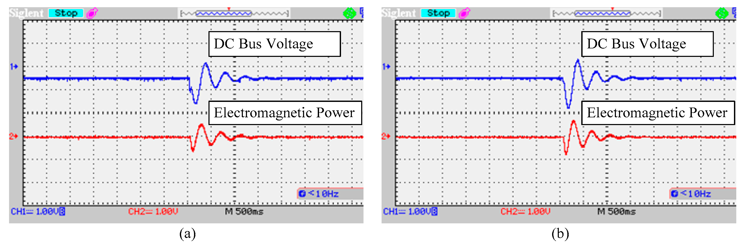
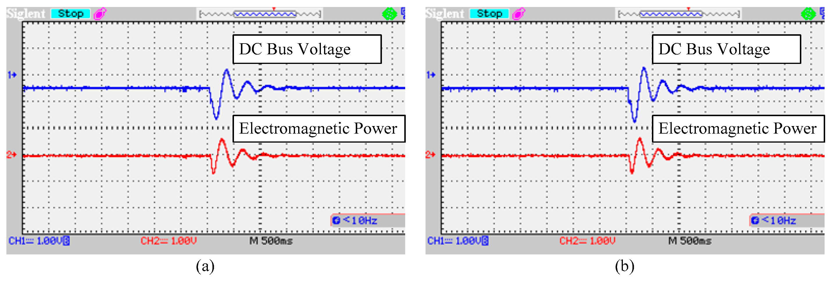
5.1. System Inertia Feature Verification

The system inertia is affected by the control parameters Dp and Kp, and are more obvious with the influence of Kp. Under the condition of keeping Dp unchanged, the influence of Kp on the system inertia characteristics is shown in Figure 9. With the increase of Kp, the oscillation amplitude of Udc under disturbance is reduced, and the oscillation period of Udc is increased. It indicates that the system’s anti-disturbance capability is enhanced, namely, the system inertia is enhanced.
The influence of Kp on Pe is shown in Figure 10. With the increase of Kp, the oscillation amplitude of Pe decreases, the speed of oscillation of Pe recovery balance increases, and the system inertia effect increases. The inertia corresponds to energy, the stronger inertia, the greater the change in Pe. Considering the stability margin limitation of the system, it is not possible to adjust Kp too large to pursue a large inertia, which affects the stable operation of the system.
Experimental results in Figure 11 demonstrate the influence of control parameter Kp on system transient stability. The system retains stability with small variations of Kp value during operation (e.g., Kp increases 0.05 to 0.1), as shown in Figure 11a,b. When Kp increases, the oscillation amplitude of Udc and Pe under disturbance is reduced, and the oscillation period of Udc and Pe is increased. That is to say, the system inertia increases. The simulation results are consistent with the experimental results.
For structural parameters, the system inertia is positively correlated with the DC bus capacitance C. The influence of structural parameter C on the system inertia is shown in Figure 12. With the increase of C, the oscillation amplitude of Udc decreases, the oscillation period of Udc becomes longer, the time for restoring balance becomes longer, and the ability to suppress interference becomes stronger. That is to say, the system inertia is enhanced. Therefore, the inertia support capability of the system can be improved by increasing the capacitance of the DC bus capacitor C.
The influence of C on Pe is shown in Figure 13. With the increase of C, the oscillation amplitude of Pe decreases, the oscillation speed of Pe decreases, and the speed of the oscillation rises also slows down. Namely, the system inertia is enhanced, and the ability to suppress external disturbances becomes stronger.
Experimental results in Figure 14 demonstrate the influence of structure parameter C on system transient stability. The system retains stability with small variations of the DC bus capacitance value during operation (e.g., C increases 4 mF to 6 mF), as shown in Figure 14a,b. When C increases, the oscillation amplitude of Udc and Pe under disturbance is reduced, and the oscillation period of Udc and Pe is increased. Namely, the system inertia increases. The simulation results are consistent with the experimental results.

5.2. System Damping Characteristics Verification

The damping characteristics of the GPVGS based on droop control are jointly affected by the control parameters Dp, Kp and Ki, but are more strongly affected by Dp. In the case of keeping Kp and Ki constant, the power angle disturbance is applied to the power grid. The damping characteristic of the system is affected by changing Dp. The simulation result is shown in Figure 15. With the decreases of Dp, the oscillation amplitude attenuation of Udc is significantly enhanced, but the oscillation period of Udc hardly changes. Namely, the damping capacity of the system is stronger.
The influence of Dp on Pe is shown in Figure 16. With the decreases of Dp, the period of system power oscillation is almost constant, and the attenuation rate of the oscillation amplitude is obviously accelerated. That is to say, the ability to suppress the oscillation is enhanced, and the damping ability is enhanced. From the variation of Udc and Pe, the control parameter Dp has the same effect on the system damping. The stronger the damping capacity, the more obvious the Pe changes.
Experimental results in Figure 17 demonstrate the influence of control parameter Dp on system transient stability. The system retains stability with small variations of Dp value during operation (e.g., Dp increases 4 to 5), as shown in Figure 17a,b. When Dp increases, the oscillation amplitude of Udc and Pe under disturbance is increased, but the oscillation period of Udc and Pe is hardly changed. Namely, the system damping capacity decreases. The simulation results are consistent with the experimental results.
Under the condition that the control parameters and the steady-state operating point parameters are kept unchanged, the influence law of the structural parameter L on the damping characteristics of the system is shown in Figure 18. With the increase of L, the oscillation amplitude of Udc becomes larger and larger. However, the oscillation period of Udc is obviously unchanged. That is to say, the damping capacity is weaker.
The influence of structural parameter L on Pe is shown in Figure 19. With the decreases of L, the oscillation amplitude of Pe becomes smaller and smaller, but the oscillation period of Pe changes insignificantly. It shows that the system damping capacity is stronger. Therefore, the system damping capacity can be improved by reducing inductance L.
Experimental results in Figure 20 demonstrate the influence of structure parameter L on system transient stability. The system retains stability with small variations of equivalent inductance value during operation (e.g., L increases 4 mH to 8 mH), as shown in Figure 20a,b. When L decreases, the oscillation amplitude of Udc and Pe under disturbance is decreased, but the oscillation period of Udc and Pe is hardly changed. That is to say, the system damping capacity increases. The simulation results are consistent with the experimental results.

5.3. System Synchronization Feature Verification

The synchronization characteristic of the GPVGS based on the droop control is only determined by the control parameter Ki. Figure 21 shows the influence law of changing Ki on the synchronization characteristics of the system under the condition of keeping Dp and Kp unchanged. With the increase of Ki, the oscillation amplitude of Udc is not obvious, but the oscillation period of Udc is obviously shortened, indicating that the synchronization capability of the system is enhanced.
The influence of Ki on Pe is shown in Figure 22. With the increase of Ki, the oscillation period of Pe changes significantly. While the oscillation amplitude and the attenuation speed of Pe change little, indicating that the system synchronization effect is enhanced. At the same time, it can be seen that with the enhancement of the system synchronization capability, Udc and Pe change more obviously. The greater the change amplitude of Udc, the greater the change corresponding to Pe. Considering the system dynamic effect speed, Ki should be selected in an appropriate range.
Experimental results in Figure 23 demonstrate the influence of control parameter Ki on system transient stability. The system retains stability with small variations of Ki value during operation (e.g., Ki increases 4 to 6), as shown in Figure 23a,b. When Ki increases, the oscillation amplitude of Udc and Pe under disturbance is hardly changed, but the oscillation period of Udc and Pe is significant decrease. Namely, the system synchronization capability increases. The simulation results are consistent with the experimental results.

6. Conclusions and Future Work

In this paper, the GPVGS based on droop control is taken as the research object. The mathematical model of the GPVGS on the DVC timescale dynamics is firstly established. The electric torque method is used to analyze the inertia, damping and synchronization characteristics of the GPVGS from the physical mechanism perspective. The research results show that:
(1)
The GPVGS based on droop control also has a certain inertia, damping and synchronization effect. At the same time, the equivalent inertia, damping and synchronization coefficient of the system are affected by the control parameters, structural parameters and steady-state operating points parameters, among which the adjustment control parameters are the simplest way to change the inertia, damping and synchronization characteristics of the system.
(2)
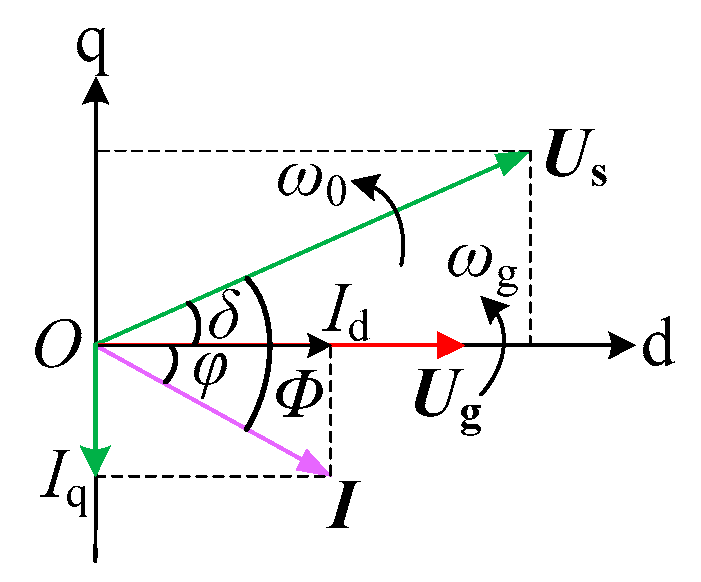
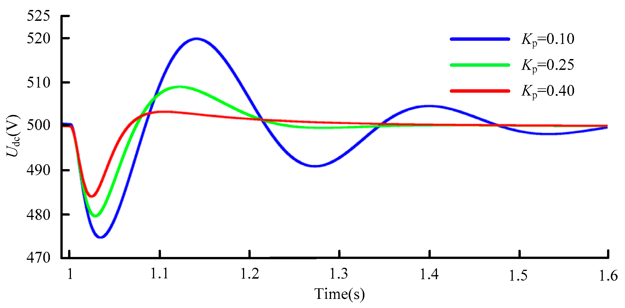
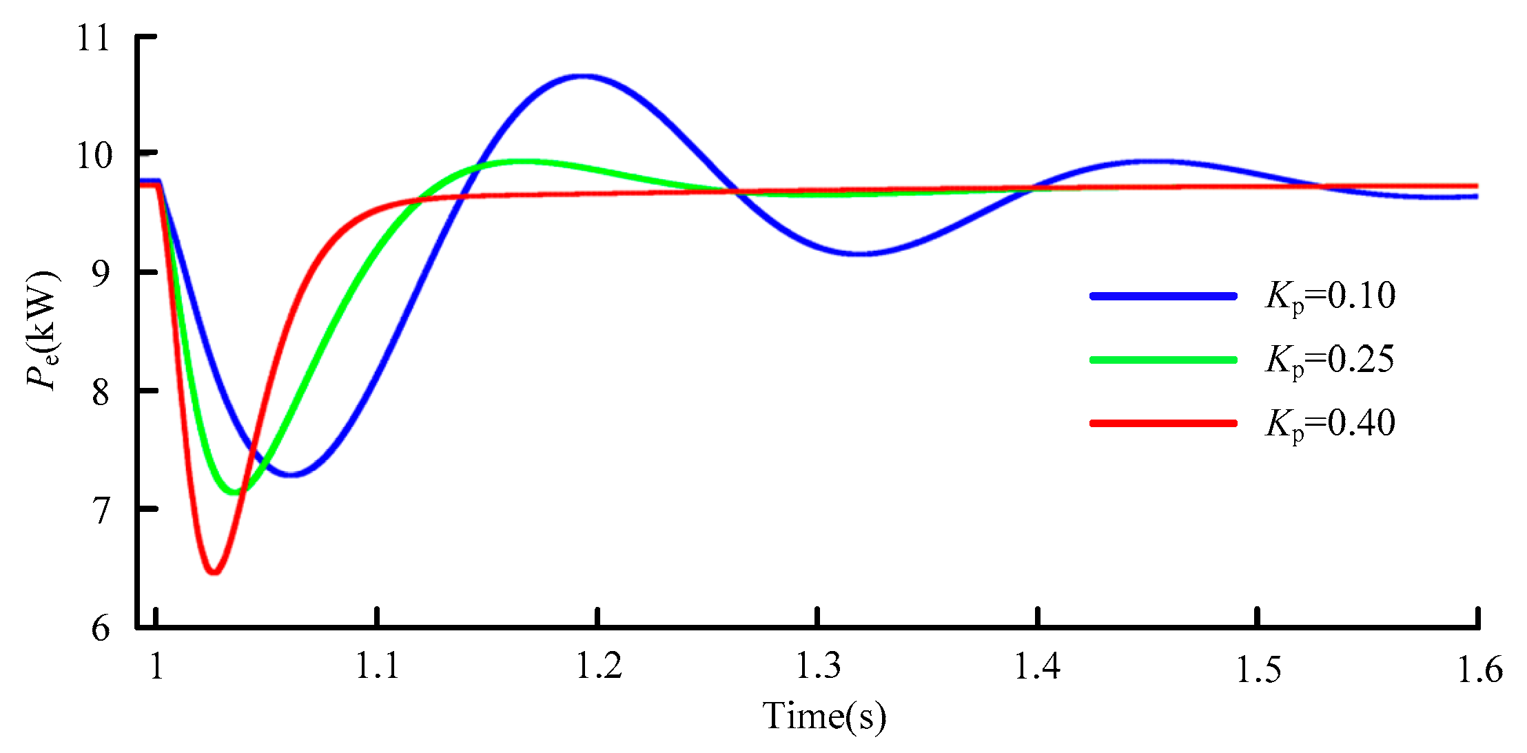
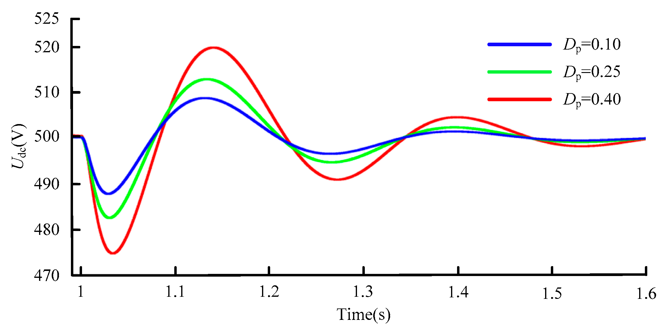
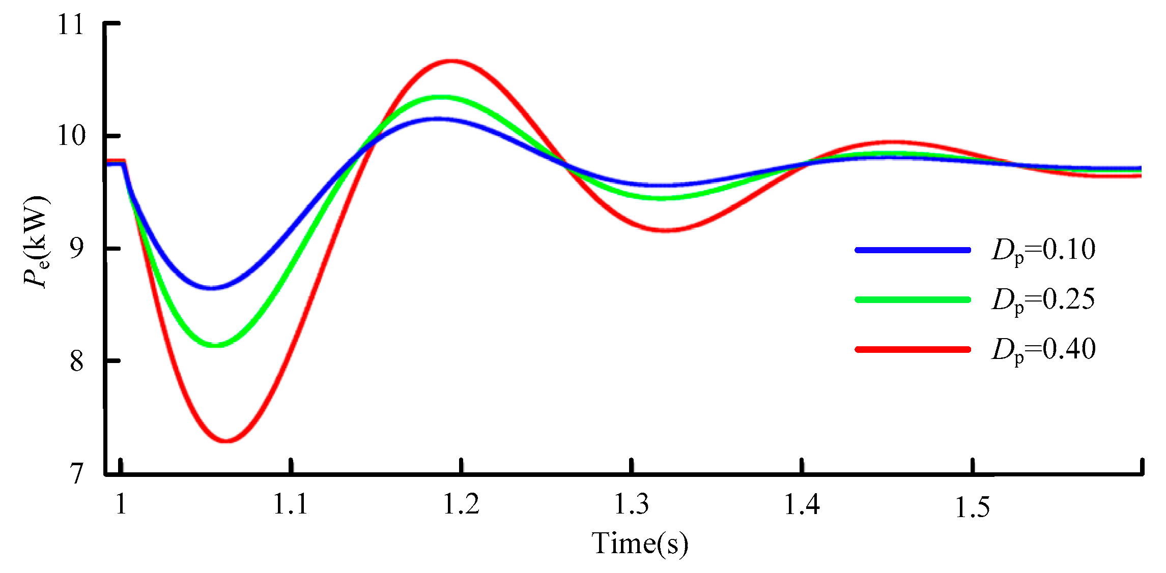
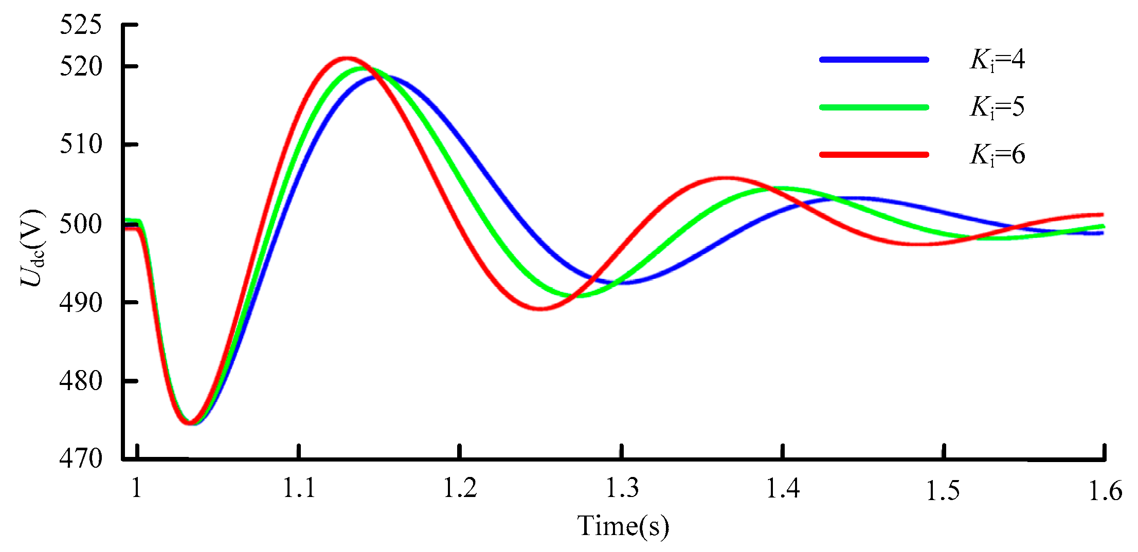
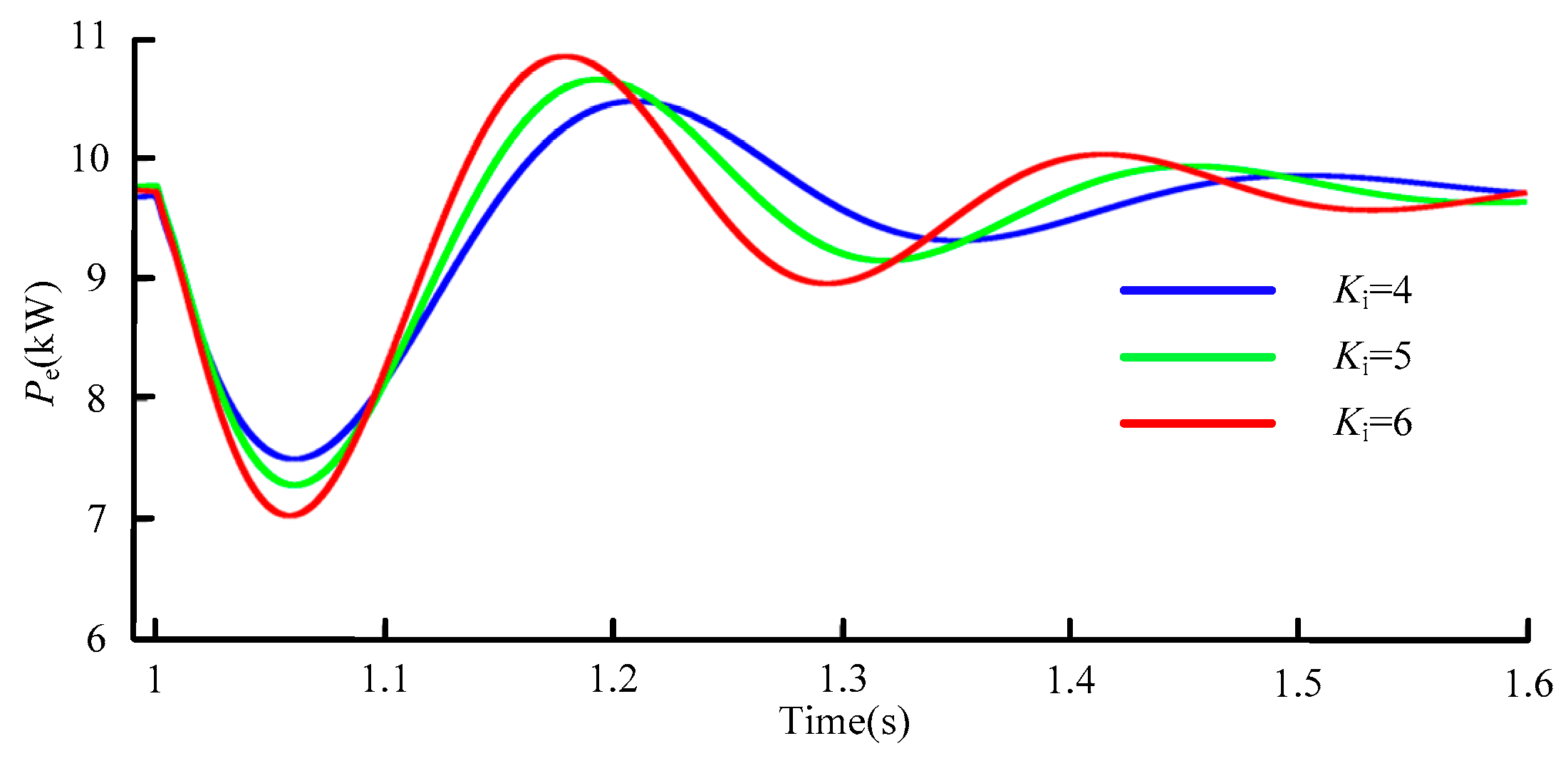
From the perspective of control parameters, the inertia characteristics of the system are influenced by the DC voltage outer loop proportional coefficient Kp and positively correlated with Kp. The damping characteristics of the system are affected by the droop coefficient Dp and negatively correlated with Dp. The synchronization effect is only affected by the DC voltage outer loop integral coefficient Ki and positively correlated with Ki.
(3)
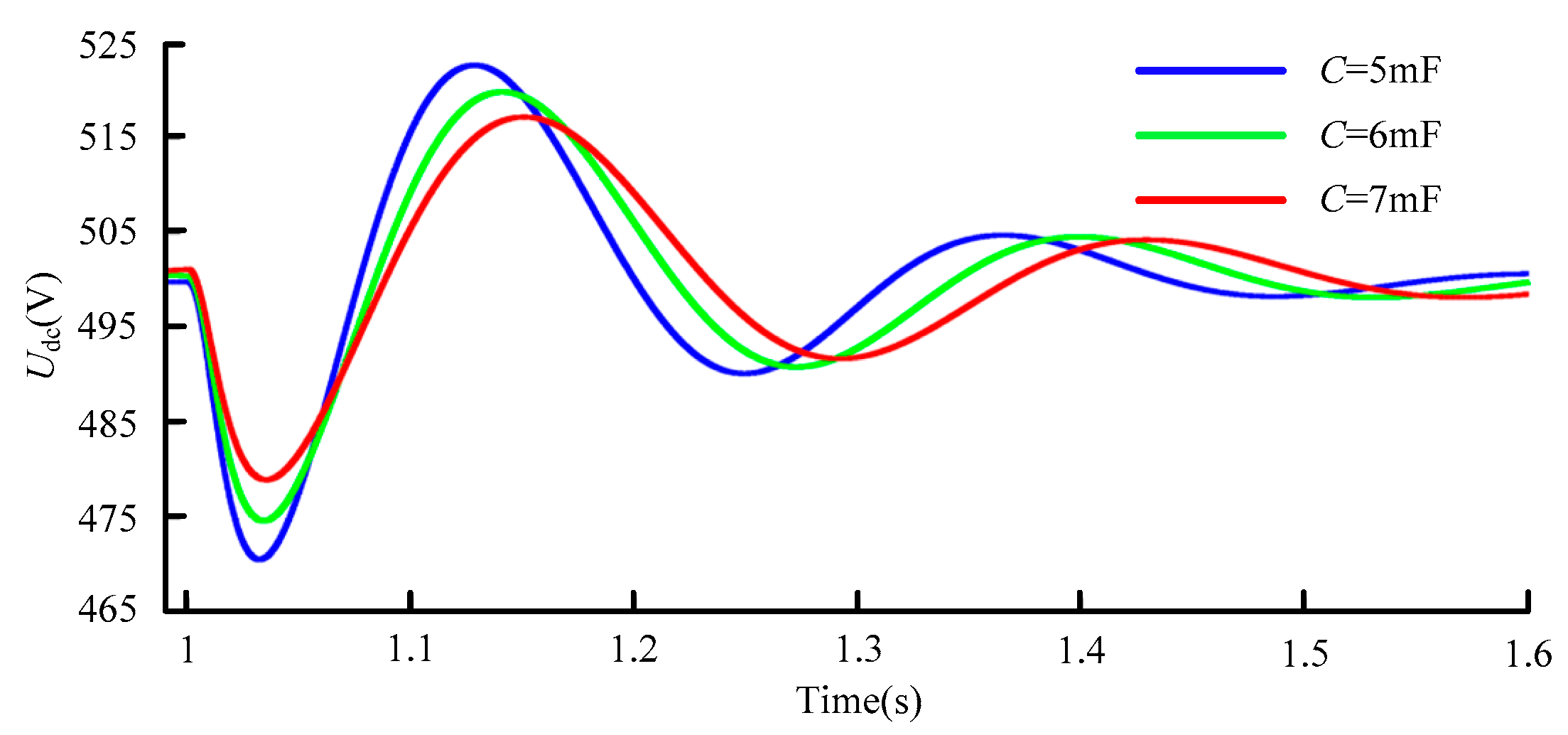
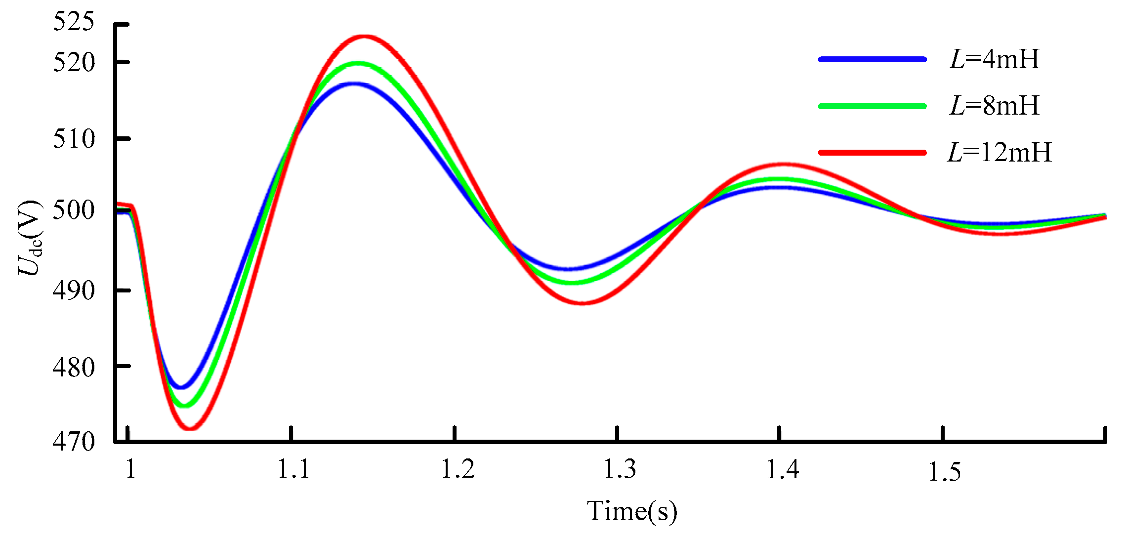
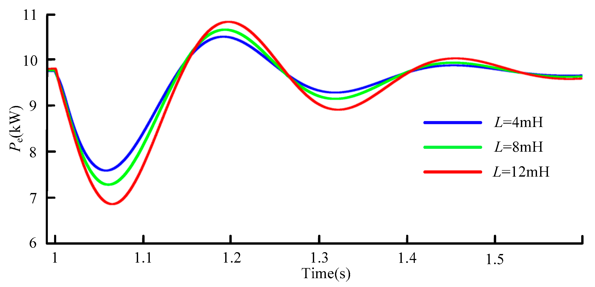
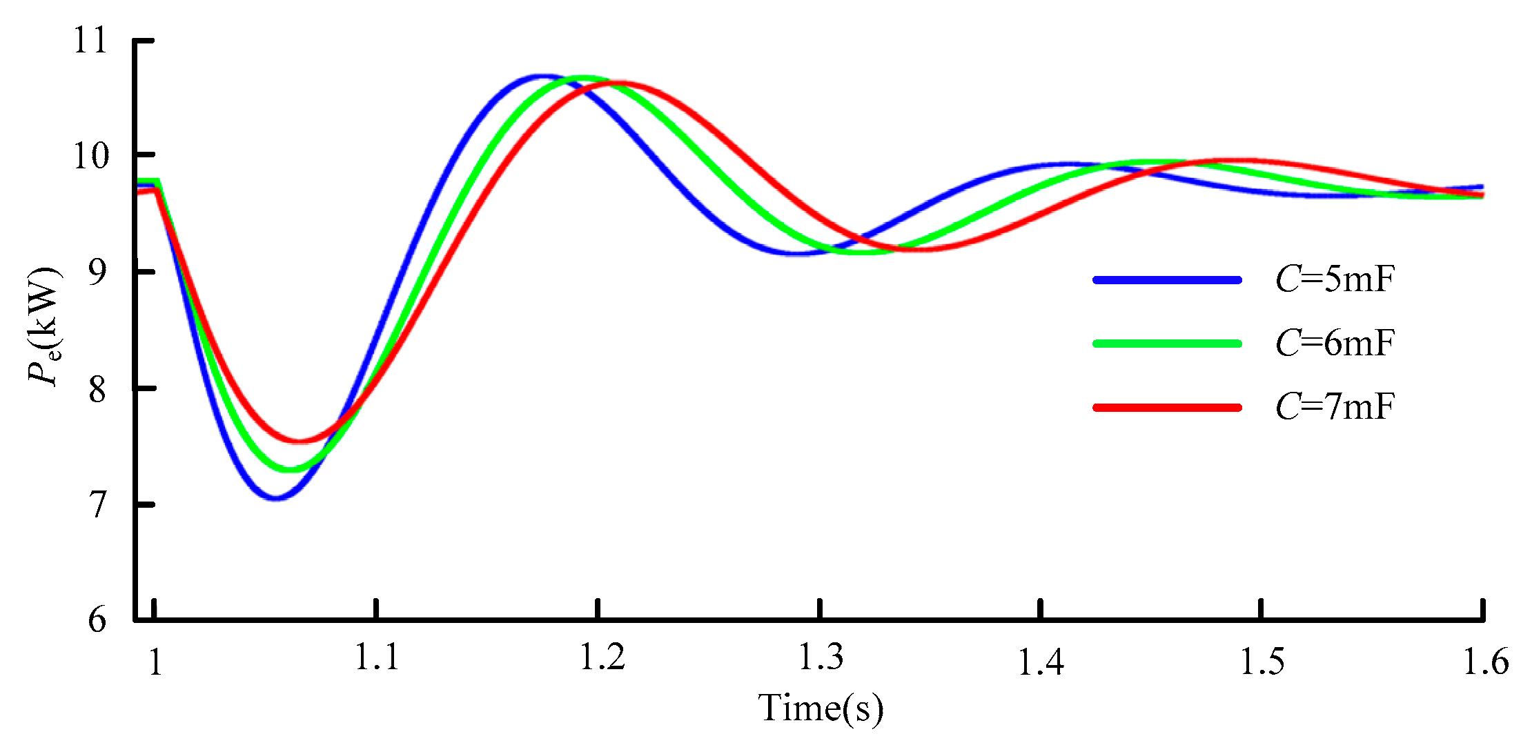
From the perspective of structural parameters, the system dynamic characteristics are affected by structural parameters such as line impedance X and DC bus capacitance C. Reducing X can improve the inertia, damping and synchronization characteristics of the system. With the increase of C, the system inertia effect is stronger.
(4)
From the perspective of steady-state operating point parameters, the system dynamic characteristics are affected by the AC/DC bus voltage level. The higher the voltage level of the bus, the stronger the grid-connected stability of the system.
(5)
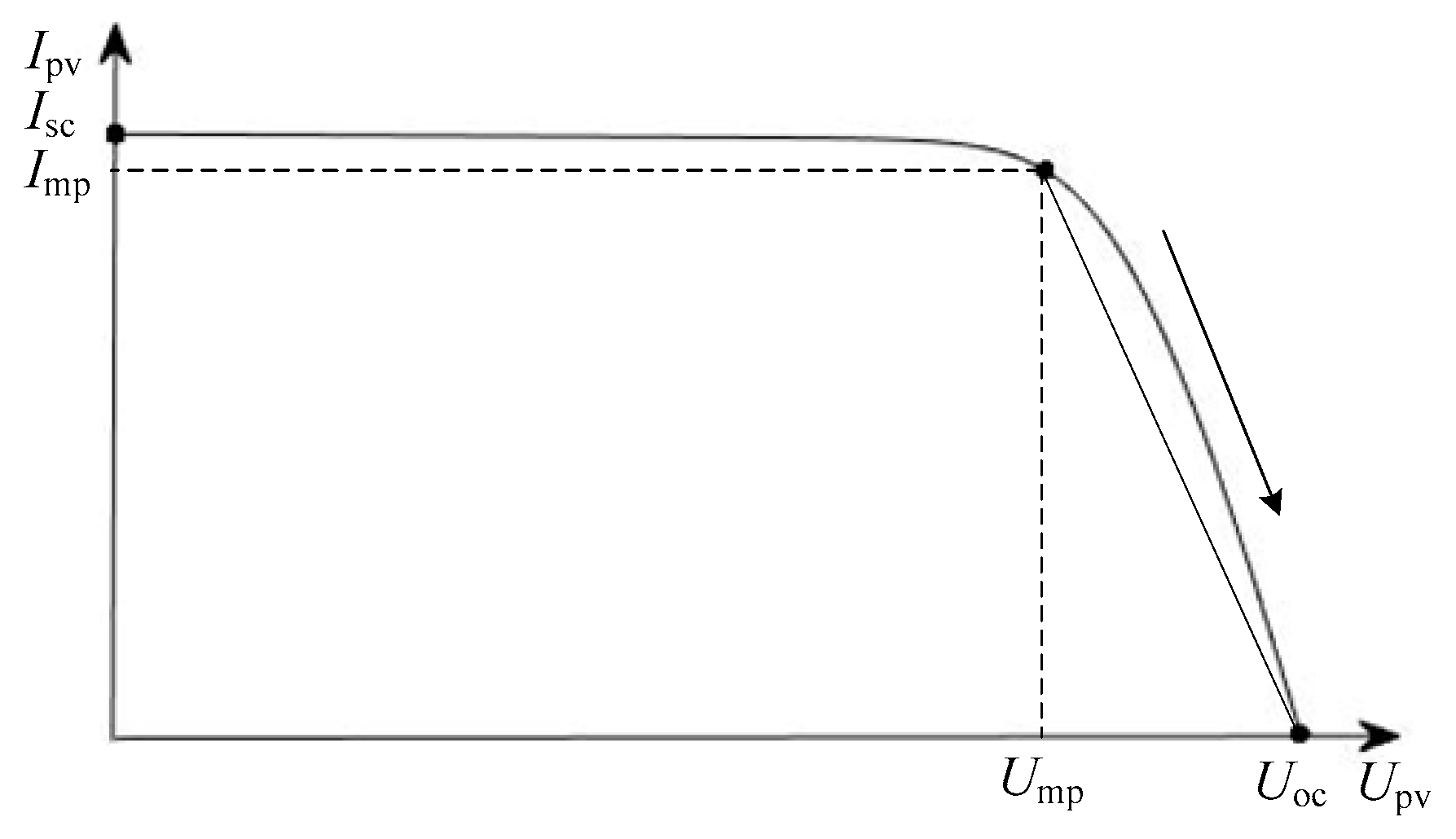
The GPVGS operating in MPPT mode do not have inertia and damping characteristics. The system can only provide inertia effects when coupled with the grid frequency.
The above research conclusions can be used as the theoretical basis of engineering practice, and the inertia, damping and synchronization characteristics of the GPVGS are rationally designed to make them more friendly to the grid.

Author Contributions

All the authors conceived of and designed the study. Y.W. and D.Z. performed the theoretical analysis and wrote the manuscript with the guidance from L.X., S.W. and Z.X.; Y.W., D.Z. and Y.Z. conceived and designed the simulation experiments.

Funding

This research was supported by the National Natural Science Foundation of China (Grant No. 51577110), the Open Research Fund of Jiangsu Collaborative Innovation Center for a Smart Distribution Network, Nanjing Institute of Technology (Grant No. XTCX201711), Shaanxi Province Industrial Science and Technology Research Project (2015GY038) and Xi’an Science and Technology Plan Project (2017068CG/RC031 (SXKD009)).

Conflicts of Interest

The authors declare no conflict of interest.

References

  1. Yang, X.; Song, Y.; Wang, G.; Wang, W. A comprehensive review on the development of sustainable energy strategy and implementation in China. IEEE Trans. Sustain. Energy 2010, 1, 57–65. [Google Scholar] [CrossRef]
  2. Blaabjerg, F.; Teodorescu, R.; Liserre, M.; Timbus, A. Overview of control and grid synchronization for distributed power generation systems. IEEE Trans. Ind. Electron. 2006, 53, 1398–1409. [Google Scholar] [CrossRef]
  3. Morjaria, M.; Anichkov, D.; Chadliev, V.; Soni, S. A grid-friendly plant: The role of utility-scale photovoltaic plants in grid stability and reliability. IEEE Power Energy Mag. 2014, 12, 87–95. [Google Scholar] [CrossRef]
  4. Mei, S.; Zheng, T.; Chen, L.; Li, C.; Si, Y.; Guo, Y. A comprehensive consensus-based distributed control strategy for grid-connected PV-VSG. In Proceedings of the 2016 35th Chinese Control Conference (CCC), Chengdu, China, 27–29 July 2016; pp. 10029–10034. [Google Scholar]
  5. Alipoor, J.; Miura, Y.; Ise, T. Power System Stabilization Using Virtual Synchronous Generator with Alternating Moment of Inertia. IEEE J. Emerg. Sel. Top. Power Electron. 2015, 3, 451–458. [Google Scholar] [CrossRef]
  6. Vega-Garita, V.; Sofyan, M.F.; Narayan, N.; Ramirez-Elizondo, L.; Bauer, P. Energy management system for the photovoltaic battery integrated module. Energies 2018, 11, 3371. [Google Scholar] [CrossRef]
  7. Xie, X.; Wang, X.; Hu, J.; Xu, L.; Bongiorno, M.; Miao, Z.; Molinas, M.; Pota, H.; Rodriguez, P. Guest Editorial: Oscillations in power systems with high penetration of renewable power generations. Iet Renew. Power Gen. 2019, 13, 1–3. [Google Scholar]
  8. Qiu, H.; Fang, J.; Tang, Y. Explore the capability of power electronic converters in providing power system virtual inertia. In Proceedings of the 2018 IEEE Energy Conversion Congress and Exposition (ECCE), Portland, OR, USA, 23–27 September 2018. [Google Scholar]
  9. Hu, J.; Yuan, H.; Yuan, X. Modeling of DFIG-Based WTs for Small-Signal Stability Analysis in DVC Timescale in Power Electronized Power Systems. IEEE Trans. Energy Convers. 2017, 32, 1151–1165. [Google Scholar] [CrossRef]
  10. Yuan, H.; Yuan, X.; Hu, J. Modeling of Grid-Connected VSCs for Power System Small-Signal Stability Analysis in DC-Link Voltage Control Timescale. IEEE Trans. Power Syst. 2017, 32, 3981–3991. [Google Scholar] [CrossRef]
  11. Fang, J.; Li, X.; Tang, Y. Grid-connected power converters with distributed virtual power system inertia. In Proceedings of the 2017 IEEE Energy Conversion Congress and Exposition (ECCE), Cincinnati, OH, USA, 1–5 October 2017. [Google Scholar]
  12. Yan, X.; Li, J.; Wang, L.; Zhao, S.; Li, T.; Lv, Z.; Wu, M. Adaptive-MPPT-based control of improved photovoltaic virtual synchronous generators. Energies 2018, 11, 1834. [Google Scholar] [CrossRef]
  13. Shintai, T.; Miura, Y.; Ise, T. Oscillation damping of a distributed generator using a virtual synchronous generator. IEEE Trans. Power Del. 2014, 29, 668–676. [Google Scholar] [CrossRef]
  14. Xiong, L.; Zhuo, F.; Wang, F.; Liu, X.; Chen, Y.; Zhu, M.; Yi, H. Static synchronous generator model: A new perspective to investigate dynamic characteristics and stability issues of grid-tied PWM inverter. IEEE Trans. Power Electron. 2016, 31, 6264–6280. [Google Scholar] [CrossRef]
  15. Ding, G.; Gao, F.; Tian, H.; Ma, C.; Chen, M.; He, G.; Liu, Y. Adaptive DC-link voltage control of two-stage photovoltaic inverter during low voltage ride-through operation. IEEE Trans. Power Electron. 2016, 31, 4182–4194. [Google Scholar] [CrossRef]
  16. Xiu, L.; Xiong, L.; Yang, P.; Kang, Z. Inertial and damping characteristics of DC distributed power systems based on frequency droop control. Energies 2018, 11, 2418. [Google Scholar] [CrossRef]
  17. Harnefors, L.; Bongiorno, M.; Lundberg, S. Input-Admittance Calculation and Shaping for Controlled Voltage-Source Converters. IEEE Trans. Ind. Electron. 2007, 54, 3323–3334. [Google Scholar] [CrossRef]
  18. Xiong, L.; Wang, D. Research on suppression mechanism of STATCOM on power oscillations. In Proceedings of the 2017 IEEE 3rd International Future Energy Electronics Conference and ECCE Asia (IFEEC 2017-ECCE Asia), Kaohsiung, Taiwan, 3–7 June 2017; pp. 806–811. [Google Scholar]
  19. Xiong, L.; Li, Y.; Zhu, Y.; Yang, P.; Xu, Z. Coordinated control schemes of super-capacitor and kinetic energy of DFIG for rystem Frequency Support. Energies 2018, 11, 103. [Google Scholar] [CrossRef]
  20. Liu, J.; Miura, Y.; Ise, T. Comparison of dynamic characteristics between virtual synchronous generator and droop cntrol in inverter-based distributed generators. IEEE Trans. Power Electron. 2016, 31, 3600–3611. [Google Scholar] [CrossRef]
  21. Xiong, L.; Xu, Z.; Xiu, L. Energy storage system control for electromechanical oscillation mitigation and its impact on inertia and damping of power system. In Proceedings of the 2018 IEEE 4th Southern Power Electronics Conference (SPEC), Singapore, 10–13 December 2018; pp. 1–5. [Google Scholar]
  22. Fang, J.; Li, H.; Tang, Y.; Blaabjerg, F. On the inertia of future more-electronics power systems. IEEE J. Emerg. Sel. Top. Power Electron. 2018, 1–19. [Google Scholar] [CrossRef]
  23. Guo, K.; Fang, J.; Tang, Y. Autonomous DC-Link Voltage Restoration for Grid-Connected Power Converters Providing Virtual Inertia. In Proceedings of the 2018 IEEE Energy Conversion Congress and Exposition (ECCE), Portland, OR, USA, 23–27 September 2018. [Google Scholar]
  24. Fang, J.; Li, H.; Tang, Y.; Blaabjerg, F. Distributed power system virtual inertia implemented by grid-connected power converters. IEEE Trans. Power Electron. 2018, 33, 8488–8499. [Google Scholar] [CrossRef]
  25. Gan, D.; Xin, H.; Liu, Y.; Wang, Z.; Yang, T. A new frequency regulation strategy for photovoltaic systems without energy storage. IEEE Trans. Sustain. Energy 2013, 4, 985–993. [Google Scholar]
Figure 1. The multi-timescale classification of system.
Energies 12 01985 g001
Figure 2. The main circuit topology and control method of the GPVGS based on droop control.
Energies 12 01985 g002
Figure 3. PV P-U characteristic curve.
Energies 12 01985 g003
Figure 4. PV U-I characteristic curve.
Energies 12 01985 g004
Figure 5. The control diagram of the boost converter.
Energies 12 01985 g005
Figure 6. Regular double closed loop control diagram of the grid-connected inverter.
Energies 12 01985 g006
Figure 7. The circuit simplified diagram of the grid-connected inverter.
Energies 12 01985 g007
Figure 8. The phasor diagram of grid-connected inverter based on grid voltage orientation.
Energies 12 01985 g008
Figure 9. Influence of control parameter Kp on system inertia.
Energies 12 01985 g009
Figure 10. Influence of control parameter Kp on system electromagnetic power Pe.
Energies 12 01985 g010
Figure 11. Influence of control parameter Kp on system stability. The Kp increases from (a) 0.05 to (b) 0.1.
Energies 12 01985 g011
Figure 12. Influence of structure parameter C on system inertia.
Energies 12 01985 g012
Figure 13. Influence of structure parameter C on system electromagnetic power Pe.
Energies 12 01985 g013
Figure 14. Influence of C on system stability. The C increases from (a) 4 mF to (b) 6 mF.
Energies 12 01985 g014
Figure 15. Influence of control parameter Dp on system damping.
Energies 12 01985 g015
Figure 16. Influence of control parameter Dp on system electromagnetic power Pe.
Energies 12 01985 g016
Figure 17. Influence of Dp on system stability. The Dp increases from (a) 4 to (b) 5.
Energies 12 01985 g017
Figure 18. Influence of structure parameter L on system inertia.
Energies 12 01985 g018
Figure 19. Influence of structure parameter L on system electromagnetic power Pe.
Energies 12 01985 g019
Figure 20. Influence of L on system stability. The L increases from (a) 4 mH to (b) 8 mH.
Energies 12 01985 g020
Figure 21. Influence of control parameter Ki on system synchronization.
Energies 12 01985 g021
Figure 22. Influence of control parameter Ki on system electromagnetic power Pe.
Energies 12 01985 g022
Figure 23. Influence of Ki on system stability. The Ki increases from (a) 4 to (b) 6.
Energies 12 01985 g023
Table 1. Electrical parameters of PVA under standard conditions.
ParametersValueParametersValue
Open circuit voltage, Uoc334 VMaximum power point, Ump262 V
Short circuit current, Isc40.6 AMaximum power point, Imp38.15 A
Table 2. The system simulation and experimental parameters.
ParametersValueParametersValue
PV-link capacitor, C1100 uFThe rated phase voltage of Grid, Ug220 V/50 Hz
Boost converter Inductor, Lb5 mHThe inductance of the L filter, Ls3 mH
DC-link capacitor, C6 mFGrid side line reactance, Lg5 mH
Boost switching freq.20 kHzInverter switching freq.10 kHz
DC voltage, Udc500 V

