Article

Assessment of Different Cooling Techniques for Reduced Mechanical Stress in the Windings of Electrical Machines

by
Bishal Silwal
1,2,*,
Abdalla Hussein Mohamed
1,2,
Jasper Nonneman
2,3,
Michel De Paepe
2,3 and
Peter Sergeant
1,2
1
Department of Electrical Energy, Metals, Mechanical Constructions and Systems, Ghent University, 9000 Ghent, Belgium
2
EEDT-Flanders Make, The Strategic Research Center for the Manufacturing Industry, B-9052 Gent, Belgium
3
Department of Flow, Heat and Combustion Mechanics, Ghent University, 9000 Ghent, Belgium
*
Author to whom correspondence should be addressed.
Energies 2019, 12(10), 1967; https://doi.org/10.3390/en12101967
Submission received: 23 April 2019 / Revised: 15 May 2019 / Accepted: 18 May 2019 / Published: 23 May 2019

Abstract

:
Thermal loading can induce mechanical stresses in the windings of electrical machines, especially those impregnated with epoxy resins, which is mostly the case in modern traction motors. Although designers look for cooling techniques that give better performance in terms of the power density and efficiency of the machine, several thermal cycles can lead to fatigue and the degradation of the copper insulation, epoxy and consequently the windings. In this paper, the performance of different cooling techniques has been compared based on the temperature distribution and the mechanical stress induced in the windings. Three-dimensional finite element thermo-mechanical models were built to perform the study. Two different variants of water jacket cooling, two configurations of direct coil cooling and two cases of combined water jacket and direct coil cooling methods have been considered in the paper. The results show that the combined water jacket and direct coil cooling perform the best in terms of the temperature and also the mechanical stress induced in the windings. An experimental set-up is built and tested to validate the numerical results.

1. Introduction

The steep development in the field of electric automotive and other modern traction applications has led to the demand for electrical machines with a high power density and high efficiency. This presents a challenge not only with respect to the electromagnetic design of the machine, but also the thermal design. Higher temperatures can lead to the failure of the stator winding insulation [1] and the demagnetization of the permanent magnets [2].
One of the main sources of heat in an electrical machine is the power loss in the stator windings. The losses in the stator and rotor laminations also contribute to the high temperature in the machine. In the simplest cooling scenario of radial flux machines, the heat produced in the coil is transferred to the stator, which is then radially transferred to the frame followed by natural convection to the ambient. The cooling is usually enhanced by increasing the surface area of the heat transfer by adding fins on the frame. Modern compact machines usually have epoxy impregnated windings. This is usually done, on the one hand, to enhance the heat removal, and on the other hand to prevent direct contact of the enamel coatings with air, which in turn prevents the oxidization of the coatings. However, the mismatch between the coefficients of thermal expansion of the epoxy, coating and the copper wires might lead to thermally induced mechanical stresses in the windings, which in the longer term causes the degradation of the windings.
Although the mechanical stress caused by thermal loading has been widely studied for electronics packages, power electronics and other fields [3,4,5], very little work was found for electric machines. One reason could be that the coefficients of thermal expansion of copper and coating are similar, which means that the stress induced in such case would be of much lower magnitude to cause significant consequences. However, the impregnation of the windings with epoxy have relatively much more significant consequences due to the difference in the expansion coefficients, as epoxy typically has a high coefficient of thermal expansion compared to copper and coatings. This presents the need for a comprehensive study of such stresses.
Although a brief study about the possible failure due to the difference in the thermal expansion ratios in electric machines was first presented in [6], detailed studies were not published until recently [7,8]. In our recent study on a similar topic [9], very high stresses were seen in the epoxy and also in the copper wire. The effect of the copper fill factor, thermal expansion coefficient of the epoxy and local temperature on the magnitude of the stress was also studied. The results showed that an increased copper fill factor and the use of epoxy with a low thermal expansion coefficient helps to prevent high stresses. Another way to reduce the mechanical stress in the winding is to limit the temperature in the winding.
The temperature in different parts of the machine can be limited below the safe level by reducing the losses or by improving the cooling techniques. Beside the heat removal with conduction, radiation and natural convection, electric machine cooling can be further enhanced by forced convection using a shaft-mounted fan to transfer the heat from the rotor surfaces and end-windings. Several other cooling methods have been designed and their application in different machine types has been explained in the literature. Water jacket cooling [10,11,12] is one of the most commonly used liquid cooling system in electrical machines, which is basically a water-cooled housing for the stator core. The cooling efficiency is mainly determined by one of several possible configurations of the water-jacket channels and the number of cooling paths [13].
Another commonly used cooling method is the direct coil cooling [14,15,16], which is an effort to bring the coolant closer to the heat source. This type of cooling system is often achieved by pumping oil through the coils or by placing axial cooling tubes in the slot together with the coils, where a coolant flows through the tubes.
The stator end-windings are also subjected to very high temperatures. Therefore, special attention is given to the end-winding cooling. Different end-winding cooling techniques are discussed in the literature [17,18]. Lately, the increasing use of compact machines with high power density, especially for traction applications has created interest in special cooling systems for electrical machines. Some of them are reviewed and discussed in [19,20,21]. Nevertheless, all the cooling systems are designed in order to keep the temperature of the machine under a safe limit.
In this paper, we assess the water jacket cooling and direct coil cooling techniques not only with respect to the temperature distribution over the volume, but also with respect to the mechanical stress induced due to the thermal loading of the machine, especially in the windings of the machine. The study is performed by using a three-dimensional combined thermo-mechanical finite element model. In addition, some parametric studies are performed by varying the thermal expansion coefficient of the epoxy used in the winding. The numerical results are then validated by measurements on an experimental set-up identical to that used in the simulations at the end of the paper.

2. Cooling Techniques Under Study

The following three cooling techniques are considered in this study. In all the cooling cases, the inlet temperature of the coolant and the flow rate is set to 15 °C and 5 l/min, respectively.

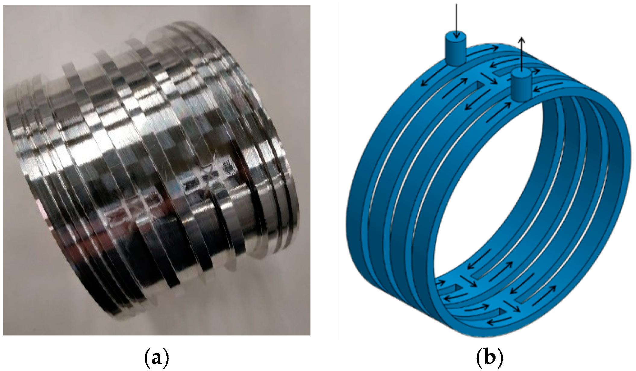
2.1. Water Jacket Cooling

The first type is a conventional jacket cooling. Two different variants of the jacket cooling have been studied in the paper. The first configuration (WJ1) consists of 36 circular axial channels, of which 3 are in series and 12 are in parallel. The second configuration (WJ2) has two main channels connected in parallel. Each of these two channels has two sub-channels connected in series. WJ2 without an enclosure is shown in Figure 1. The coolant in both the variants is water.

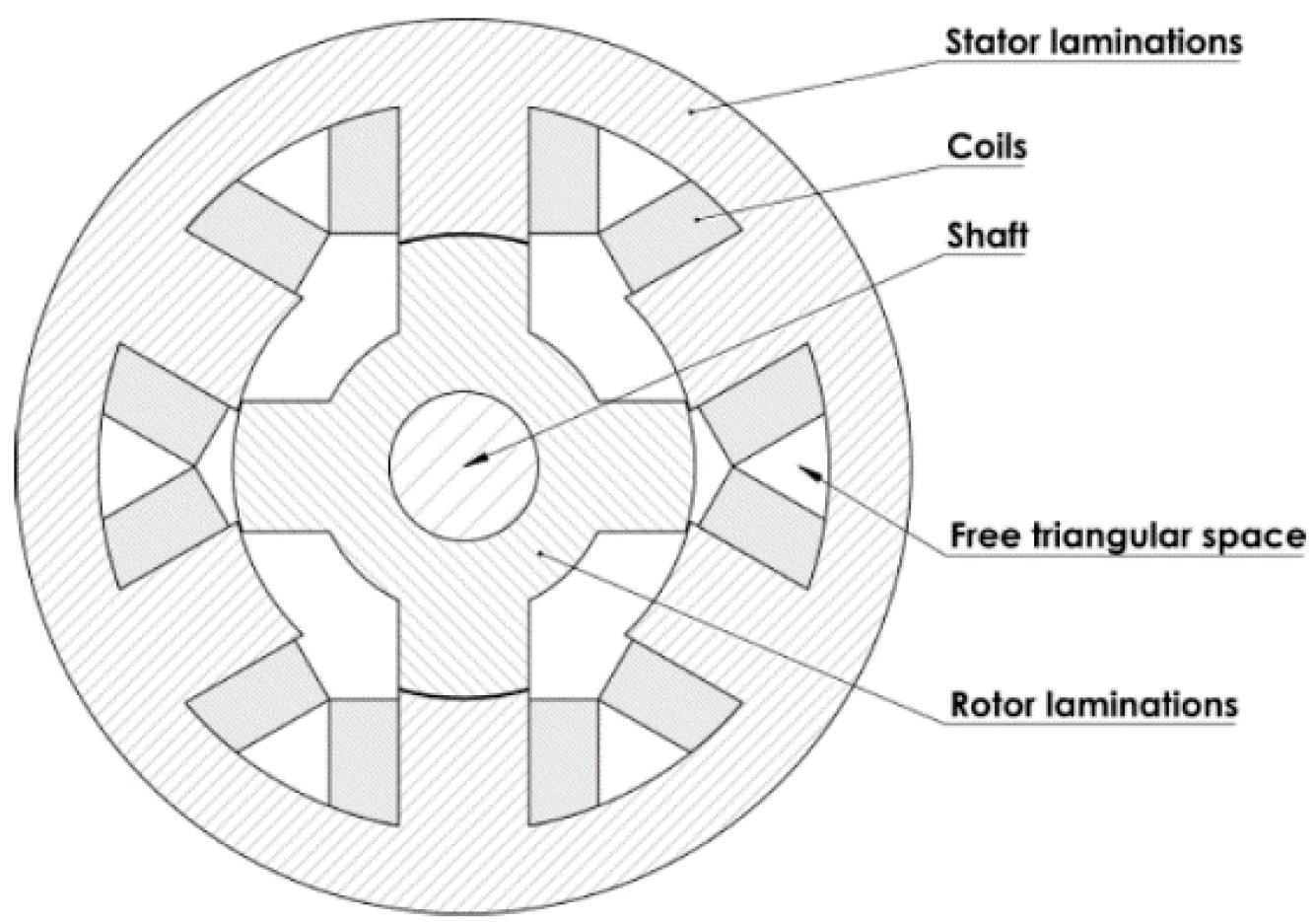
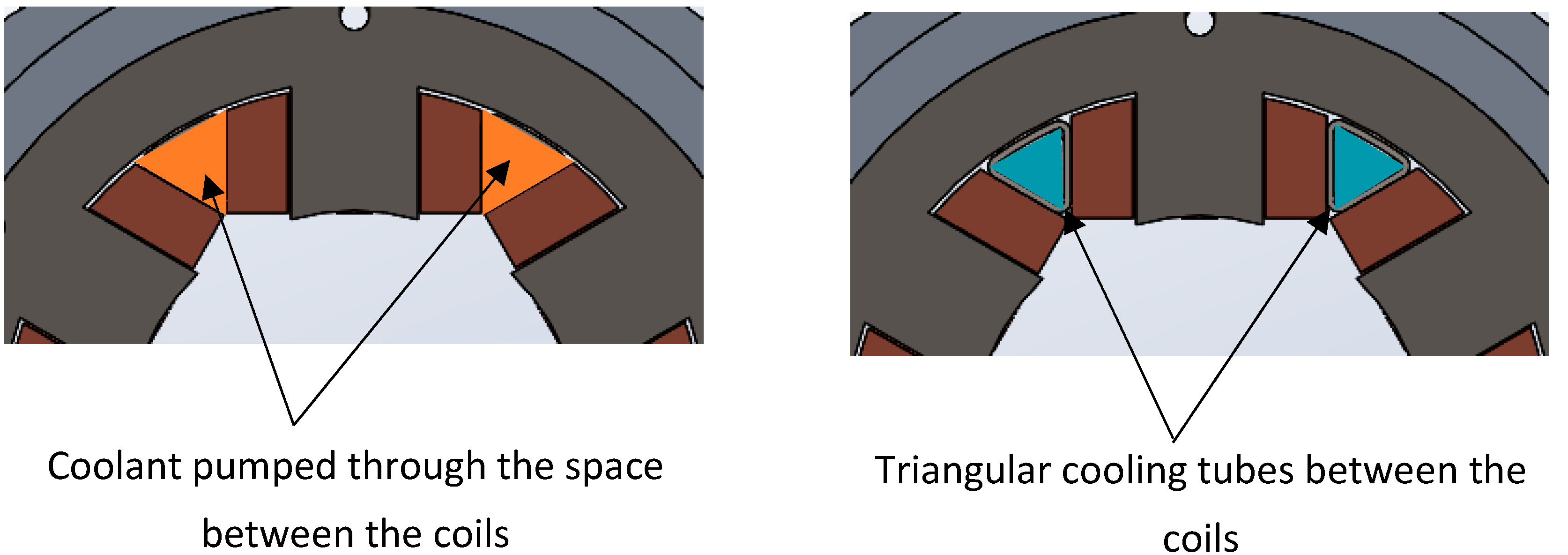
2.2. Direct Coil Cooling

Two different configurations of direct coil cooling have been studied in this paper. Both configurations are shown in Figure 2. The first configuration (DCC1) involves pumping the coolant axially through the stator slot, in the free space between two adjacent coils where no coil is present due to the use of preformed coils. In the machine considered in this paper, it results in six direct cooling channels, which are all connected in series. Since the coolant in this case is directly in contact with the coil, an automatic transmission fluid (ATF) is used as the coolant.
The second configuration (DCC2) consists of using triangular tubes made of stainless steel in the free spaces between the coils. The resulting six axial tubes are connected in series. Water is used as the coolant.

2.3. Combined Water Jacket and Direct Coil Cooling
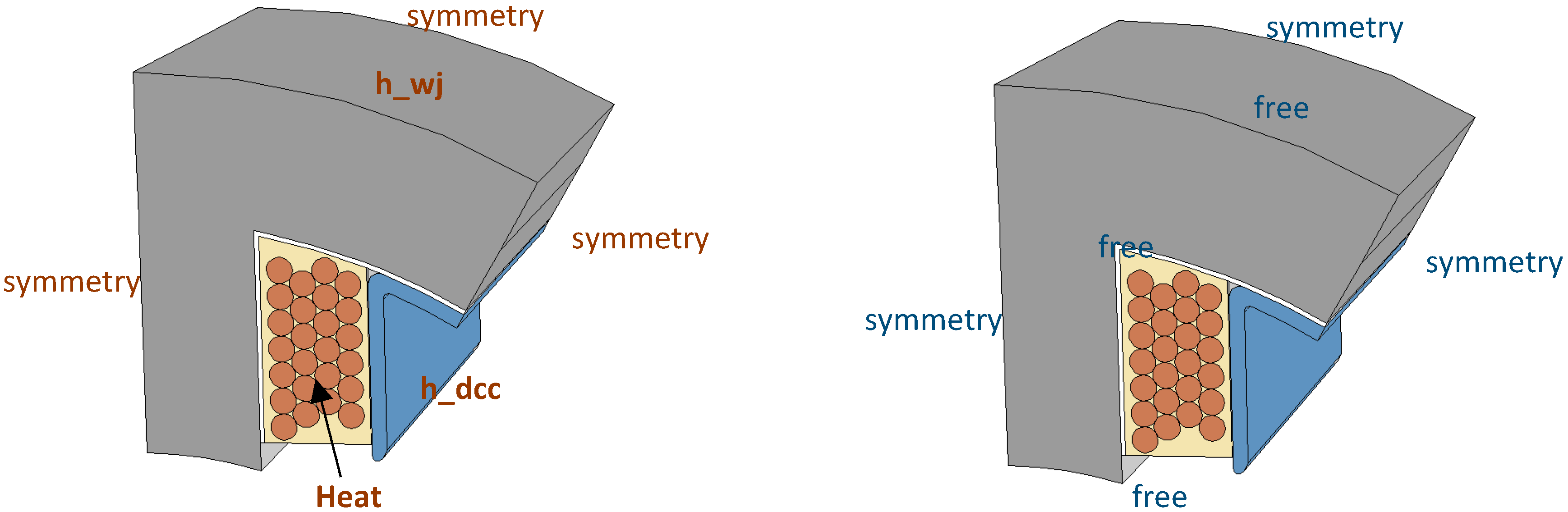
Furthermore, the combinations of both water jacket cooling and direct coil cooling are studied. The two different combinations of the aforementioned water jacket and direct coil cooling techniques taken into account in the paper are WJ1 + DCC1 and WJ2 + DCC2.

3. Numerical Model

The mechanical stress in the stator windings due to thermal loading is investigated by using three-dimensional finite element analysis. For this purpose, 3-D thermo-mechanical models are simulated in Comsol Multiphysics software. A stator of a six-pole switched reluctance machine, shown in Figure 3, is used as a test machine in the study. The most relevant geometrical dimensions of the machine are listed in Table 1. The machine has form wound concentrated windings with 25 turns per slot. The diameter of each conductor is 1.9 mm.
To simplify the three-dimensional numerical model, the geometry of the machine is subjected to some simplifications. Only a segment of the stator and half of the effective axial length of the machine is modelled in the simulations. The enamel coatings of the copper wires are also not included in the model. Table 2 lists some of the properties of the materials used in the model.
Combined thermo-mechanical models are developed to perform this study such that first a temperature distribution over the overall volume is calculated by solving a thermal model and then the computed temperature is used as an input in the mechanical model. The influence of the temperature is taken into account in the structural model by implementing Equation (1) in the model which defines the thermal strain caused by the change in temperature.
ε t h = α ( Δ T )
The water jacket and the direct coil cooling are modelled by using convective heat transfer coefficients, which are calculated as explained in Section 4. In the structural model, a symmetric boundary condition has been used on adjacent sides in the circumferential direction. Since only half of the axial length is used in the simulations, the back face of the geometry has also been modeled with a symmetric boundary, while the front face is free to move. The upper and lower face along the radial direction are also modeled as free to move. The geometry used in the study together with the boundary conditions used in both the thermal and mechanical simulations are more clearly illustrated figuratively in Figure 4.
The mechanical stresses in the stator core, copper wires and epoxy are determined for the temperature distribution obtained in case of water jacket cooling, direct coil cooling and combined water jacket and direct coil cooling. The results and discussion for all the cases studied are presented in the following sections. The stress is shown as the von-Mises stress, which is calculated as
σ v o n m i s e s = 1 2 { ( σ 11 σ 22 ) 2 + ( σ 22 σ 33 ) 2 + ( σ 33 σ 11 ) 2 + 6 ( σ 12 2 + σ 23 2 + σ 31 2 ) }
where σ11, σ22, and σ33 are the tensile stress coefficients which act along the axes and σ12, σ23, and σ31 represent the shear stress which act along the planes.

4. Calculation of Heat Transfer Coefficients

In this paper, the heat removal through the water jacket has been modelled by using an equivalent heat transfer coefficient on the outer surface of the stator (inner surface of the water jacket). This equivalent heat transfer coefficient represents the heat transfer through the jacket to the fluid and constitutes two components—one component due to the convection in the jacket channels and another component due the conduction from the channel walls to the inner surface of the jacket. The convection coefficient h within the channels is calculated based on the mean Nusselt number Nu, which is
N u = h D h k
where D h = 4 A P is the hydraulic diameter of the channel, A is the cross-sectional area of the flow, P is the wetted perimeter of the cross-section and k is the thermal conductivity of the fluid. In case of laminar flow, the mean Nusselt number Nu is calculated with the correlation of Spang et al. [22] for laminar simultaneously developing flow in a circular duct, given by Equation (4) and which is valid for Re < 2300. The mean Nusselt number for turbulent flow is calculated based on the Gnielinski correlation shown in Equation (5) which is valid for turbulent flow (Re > 2300) in a duct, with a correction factor for the development of the flow of Bhatti and Shah [23] given in Equation (6).
N u = ( 4.364 3 + ( 1.953 ( R e P r D h L ) 1 3 ) 3 + ( 0.924 P r 1 3 ( R e D h L ) 0.5 ) 3 ) 1 3 ( P r P r w ) 0.11
N u = f 8 ( R e 1000 ) P r 1 + 1.12.7 f / 8 ( P r 2 / 3 1 ) ( P r P r w ) 0.11
N u N u = 1 + C 6 L / D h ,   with   C 6 = ( L / D h ) 0.11 P r 1 / 6 ( 0.68 + 3000 R e 0.81 )
In these equations, the friction factor f is determined by the correlation of Petukhov: f = ( 0.79 ln ( R e ) 1.64 ) 2 , Re is the Reynolds number, Pr and Prw are the Prandtl number of the flow at, respectively, the bulk and wall temperature (for which an iteration is included); L is the length of the channel.
The second component in the equivalent heat transfer coefficients, which is the conduction through the jacket material, depends on the type of jacket. WJ1 can be assumed to be symmetric in a plane perpendicular to the axis and WJ2 can be assumed to be axisymmetric. Both conductive problems can therefore be simulated with the 2D FE software package FEMM. In simulation, the geometry of a section of half of a stator tooth is used for WJ1 and an axisymmetric section of the jacket is used for WJ2. The boundary conditions are set as:
  • convection at the jacket channel walls with water at the given temperature (Tin) and with the convection coefficient calculated by Equations (3)–(6).
  • a heat flux q = Q A j at the inner side of the jacket, with the total heat generation Q (in Watts) and Aj the surface area of the inner surface of the jacket.
  • conduction in the jacket material, with a conduction coefficient of the material (Aluminum in this case).
  • all other surfaces adiabatic.
The equivalent heat transfer coefficient heq defined onto the inner surface of the jacket Aj can now be determined from Equation (7),
h e q = q T j T i n
with Tin the inlet temperature of the coolant, Tj the average inner jacket temperature and q heat flux.
The convection coefficient in the triangular channels (DCC1) and tubes (DCC2) between the windings in the case of direct coil cooling is calculated with the same Equations (3)–(6).
The convective heat transfer coefficient determined by using afore-described method for the cooling cases studied in this paper are listed together with their other properties in Table 3.

5. Comparison of Cooling Techniques

Combined thermo-mechanical simulations are performed for all the cooling cases described in Section 2. For the thermal simulation in all the cases, it is assumed that the total copper loss in the stator windings of the machine is 300 W. For the mechanical simulations, the input is the temperature distribution obtained from the thermal simulations.

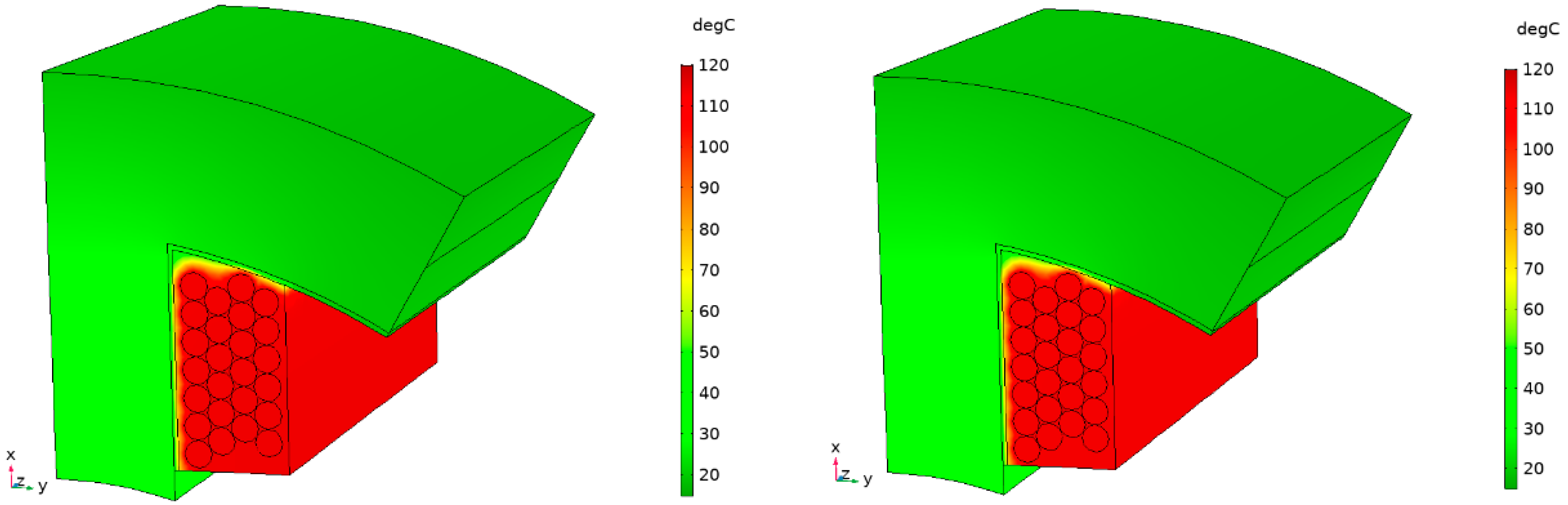
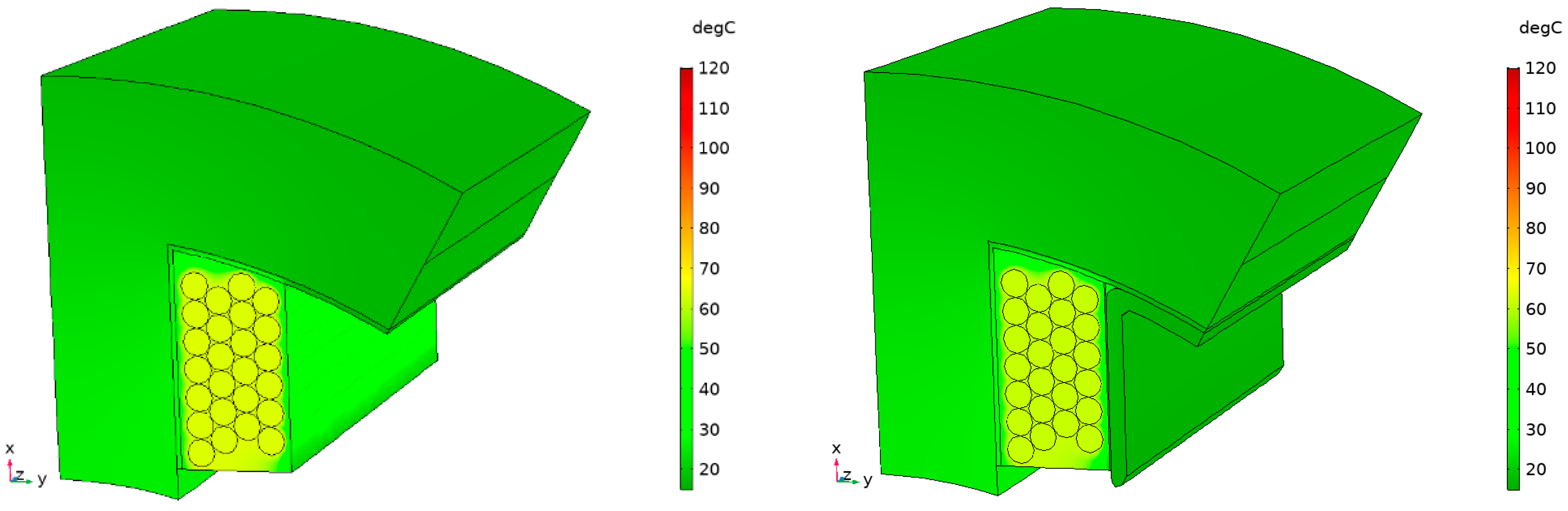
5.1. Temperature Distribution

The temperature in the machine depends on the amount of heat removed from the source. In this paper, different cooling techniques are compared. The temperature in the machine for each case depends on how the heat is removed. Figure 5 shows the heat flow path for different cases.
When the machine is cooled with the water-jacket, the heat from the coils flows to the tooth and the yoke of the machine and radially convects through the water jacket, as shown in Figure 5a. In case of direct coil cooling (Figure 5b,c), the coils close to the coolant dissipate heat directly, but a significant part of the generated heat conducts through the stator tooth to the yoke before finally convecting through the cooling tube. This results in higher temperatures in the stator tooth and yoke compared to the former case. In the case of combined water-jacket and direct coil cooling, the heat generated in the coil follows two paths resulting in lower temperatures in the overall domain.
The temperature distributions obtained from the simulation of different cooling cases are shown in Figure 6, Figure 7 and Figure 8. For easy comparison, the color scale is set to the same range in all the figures. In Figure 6, the temperature distributions in the case of the two water-jacket configurations are shown. Even though the geometries of WJ1 and WJ2 are different, the heat flow and the convective heat-transfer coefficients do not differ much. Therefore, the distribution of the temperature in the overall volume is almost the same in both the cases. The maximum temperatures are also about the same with 115 °C in the coils in the case of WJ1 and 114 °C in the case of WJ2. The maximum temperature in the stator core is about 37 °C in both cases.
The heat transfer coefficient for DCC2 is significantly higher than that of DCC1. This reflects on the temperature distribution obtained from the simulations, which is shown in Figure 7. In DCC1, the maximum temperature of 108 °C occurs in the coils and the average temperature in the stator core is about 84 °C. In DCC2, the temperature levels are very low compared to DCC1. In the coils, the maximum temperature obtained is about 80 °C while the average temperature is the stator core is about 56 °C, which is about one-third of that in DCC1.
The results show that the combined water-jacket and direct coil cooling seem to deliver much lower temperature levels. Figure 8 shows the temperature distribution obtained from the thermal simulations for combined water-jacket and direct coil cooling cases. Since the heat is removed via two different cooling paths, the temperature level is much lower compared to cooling with water-jacket or direct coil cooling separately. The maximum temperature in the copper wire is 63 °C in the case of WJ1 + DCC1 and 61 °C in the case of WJ2 + DCC2.

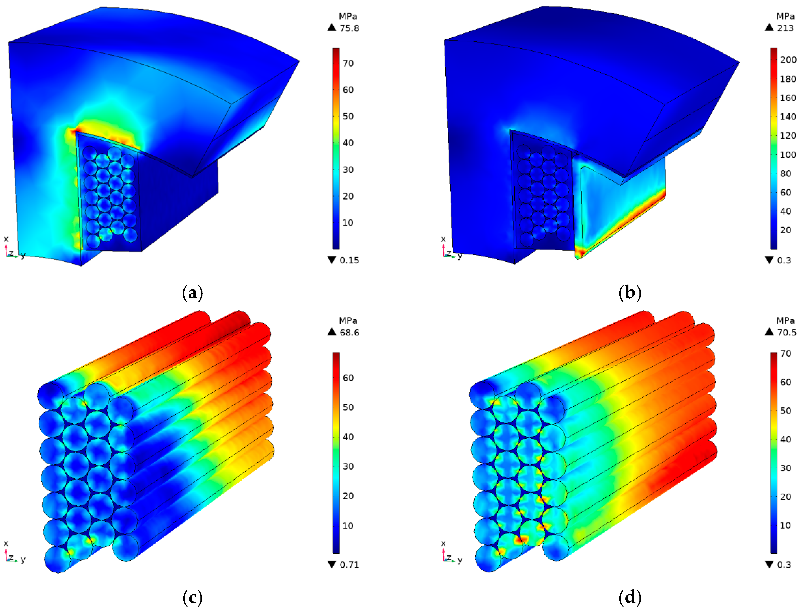
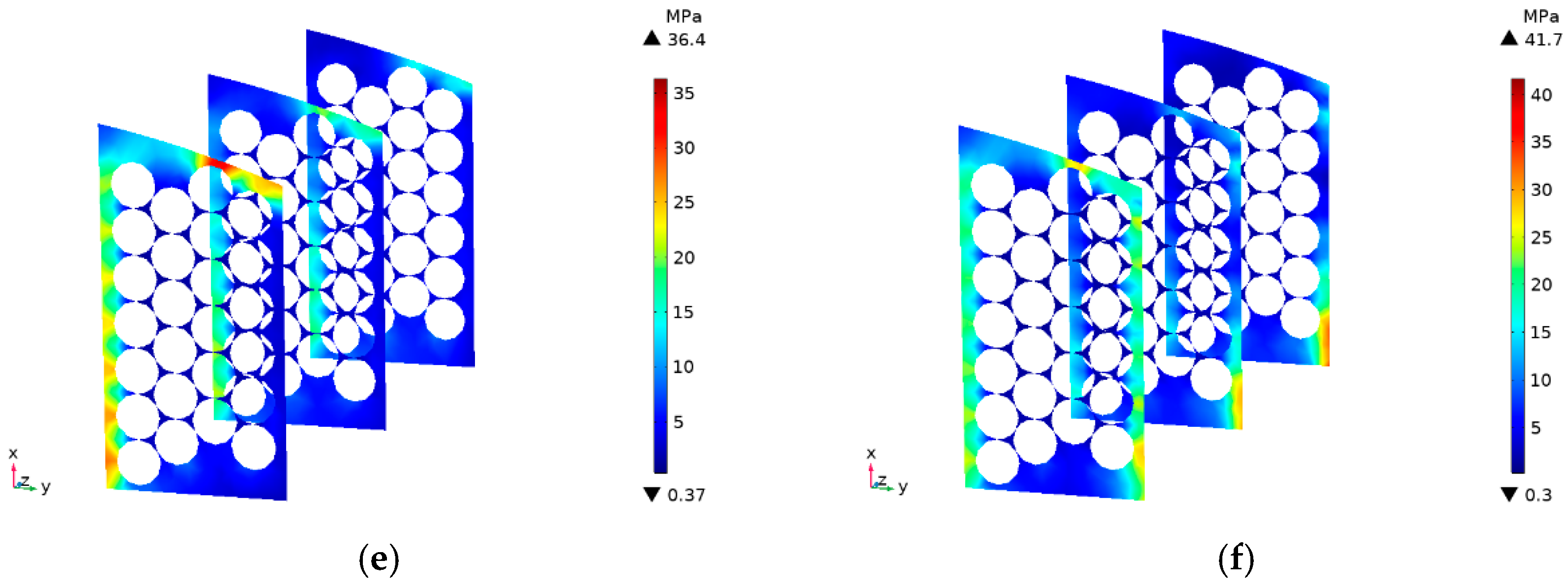
5.2. Thermally Induced Mechanical Stress

The thermally induced mechanical stress in the stator winding of the machine mainly depends on the temperature and the coefficient of thermal expansion of the materials (copper, epoxy, nomex and electrical sheet). In the simulations, the coefficients of thermal expansion of all the materials are set to a certain value listed in Table 2. Therefore, the only factor that is changed and affects the stress is the temperature distribution, which has already been shown for each cooling case in the previous section. Next, the stresses obtained are shown.
Figure 9 shows the stress in the case of water jacket cooling: WJ1 and WJ2. One can see that the stress is relatively higher in the interface region of two different materials. The reason behind this is the mismatch of the coefficient of thermal expansion of different materials. In the case of water jacket cooling, we already saw that the overall temperature distribution of both WJ1 and WJ2 was similar. The same is reflected in the stress distribution. The stress distribution and the magnitude of the stress are roughly the same in both cases.
The maximum stress occurs on the surface of the tooth in both the cases, but the stresses in the copper wires are also significantly higher. In both cases of water jacket cooling, the maximum stress occurring in the copper wires is about 144 MPa. This value is quite high especially if we think about the coatings of the copper wires. Usually, the wires are coated with polymers like Polyamide-imide, the tensile strength of which is about 250 MPa. The coefficient of thermal expansion of Polyamide-imide is about the same as copper. Therefore, the coatings will undergo similar stresses as the copper wires. Few cycles of such high stress could lead to the failure of the wire insulation. It can be seen from Figure 9c,d that most of the copper wires undergo high stresses. The relatively lower stress seen towards the front face is the result of the ‘free’ boundary condition imposed on that face. In addition, the lower sections of the wires have lower temperature gradients relative to the surrounding region. The average stress in the wires in both cases is about 87 MPa.
Figure 9e,f shows the stress in the epoxy in three different positions along the axial length of the machine. It can be seen that the epoxy can undergo stress up to 75 MPa for both WJ1 and WJ2, which is also high if we consider the tensile strength of epoxy resins. Subsequently, it could also lead to fatigue and breakdown of the epoxy.
In practice, the water jacket is also in direct contact with the stator, which means that depending upon the thermal expansion coefficient of the material of the water jacket, some stress could be induced in it. However, the temperature gradient between the stator surface and the water jacket is very low, leading to negligible stress. Therefore, it has not been considered in this study. Moreover, the water-jacket has been modeled by an equivalent convective heat transfer coefficient in the stator surface, considering a perfect contact between the outer stator surface and inner surface of the water jacket.
Figure 10 shows the stress distributions in the case of direct coil cooling with and without triangular cooling tubes. As found earlier, in the case of direct coil cooling, the temperature in the coil and in the stator core is significantly higher in the case of DCC1, compared to DCC2. Consequently, a higher stress level is seen around the interface region of the coil and the stator tooth, in the case of DCC1. In the case of DCC2, the highest stress is seen in the cooling tubes, as the temperature gradient between the coil and the cooling tube is high. In addition, there is a mismatch of the coefficient of thermal expansion of the epoxy and the steel.
It is also worth to note the difference in the magnitude and the distribution of the stress in the copper wires and the epoxy compared to the case of water jacket cooling. The maximum stresses in the copper wires in the case of DCC1 and DCC2 are 93 MPa and 87 MPa, respectively, which are comparatively lower than in the case of WJ1 and WJ2. The stress in the copper wires is high in the case of DCC1, owing to the high temperature in the coils compared to DCC2. The distribution of the stress in the copper wires is also different in these two direct coil cooling techniques. Especially in DCC2, one can see that the wires close to the cooling tube are exposed to more stress due to the temperature gradient and also the difference in the coefficient of thermal expansion.
Figure 11 shows the stress distributions in the case of combined water jacket and direct coil cooling, WJ1 + DCC1 and WJ2 + DCC2. These cooling techniques resulted in the lowest temperature levels from the thermal simulations. Consequently, the stress levels are also comparatively lower than previous cases. Between the two cases of combined water jacket and direct coil cooling, the stresses in the copper wires and epoxy have similar a level of magnitude, with WJ2 + DCC2 having slightly higher values compared to WJ1 + DCC1.

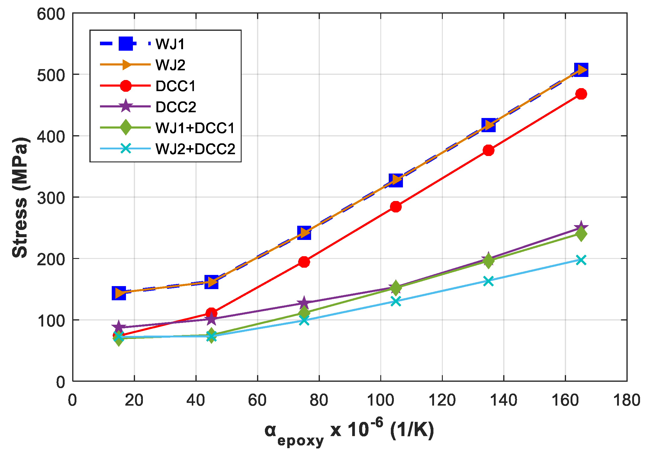
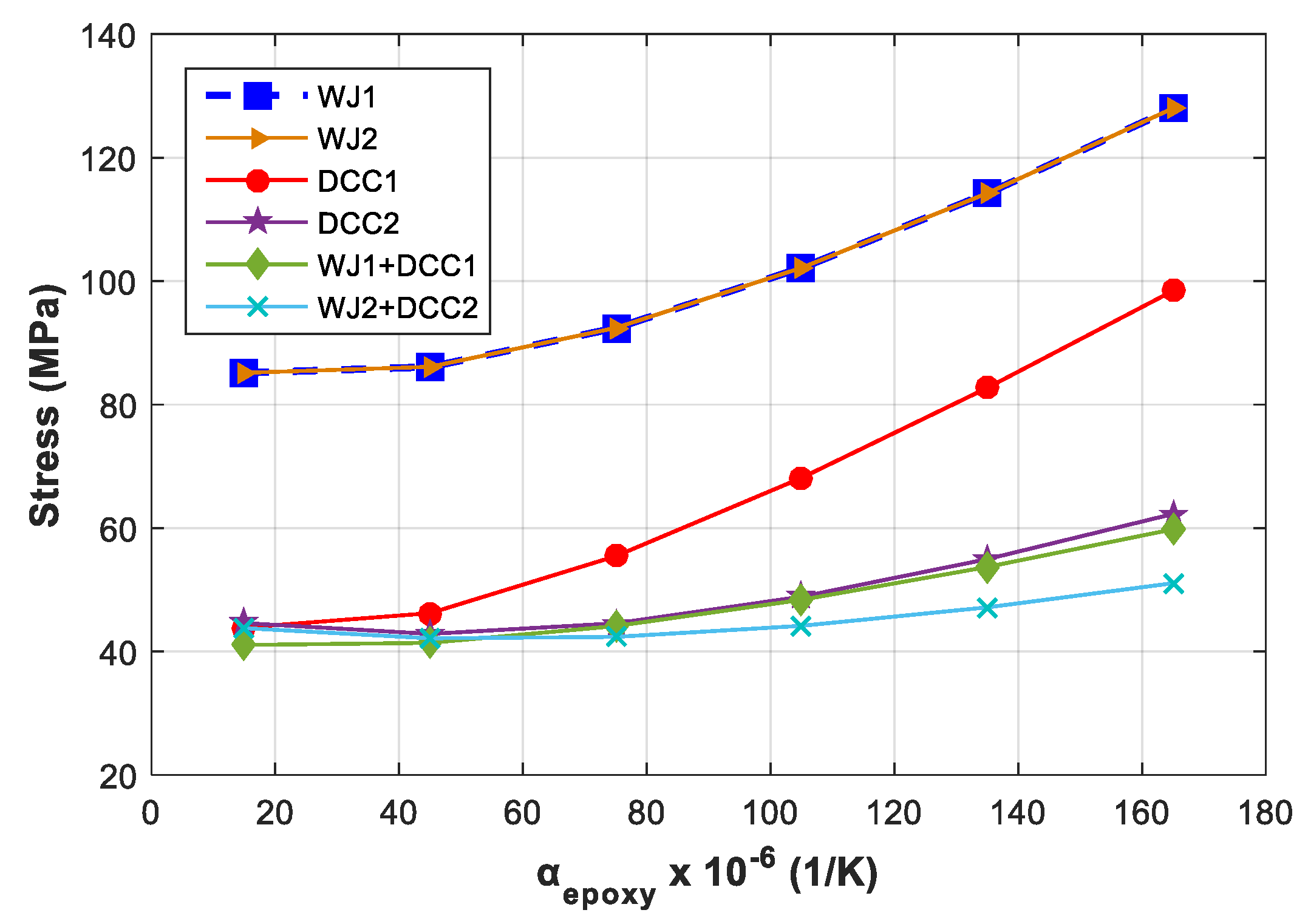
6. Effect of Different Epoxies

In the results shown in the previous section, the epoxy type used in the simulation is Epoxylite TSA 220 (Elantas Europe GmbH, Germany), which has a thermal expansion coefficient of 50 × 10−6 1/K. There are epoxy resins available in the market with a thermal expansion coefficient from 14 × 10−6 1/K to 155 × 10−6 1/K [7]. To understand the influence of the thermal expansion coefficient of the epoxy, a sensitivity analysis based on the variation of the coefficient of thermal expansion of the epoxy is performed. The thermal expansion coefficient of epoxy is varied in the range 15 − 150 × 10−6 1/K and the stresses are calculated. Figure 12 shows the maximum stress that could occur in the copper wires in all the six cases of cooling methods studied in the paper. The stress magnitudes are quite high compared to the strength of the copper and the coating that are typically used in the wires of electrical machines. The maximum stress does not occur in the overall copper volume. Therefore, the average stress in the wires can be used as an indicator of the level of stress that the wires will have to withstand. Figure 13 shows the average stress in the copper wires. It is evident from both the figures that the stress increases with the increase in the value of the thermal expansion coefficient of the epoxy. The reason behind this is that the difference in the thermal expansion coefficients of the epoxy and copper increases accordingly and the stress is dependent on the difference of the thermal expansion coefficients of the two materials. Among all the cooling methods studied, both configurations of combined water jacket and direct coil cooling—WJ1 + DCC1 and WJ2 + DCC2—have the best performance. The maximum and the average stresses in these two cases are the lowest. The next to the best case is the direct coil cooling technique using triangular tubes.

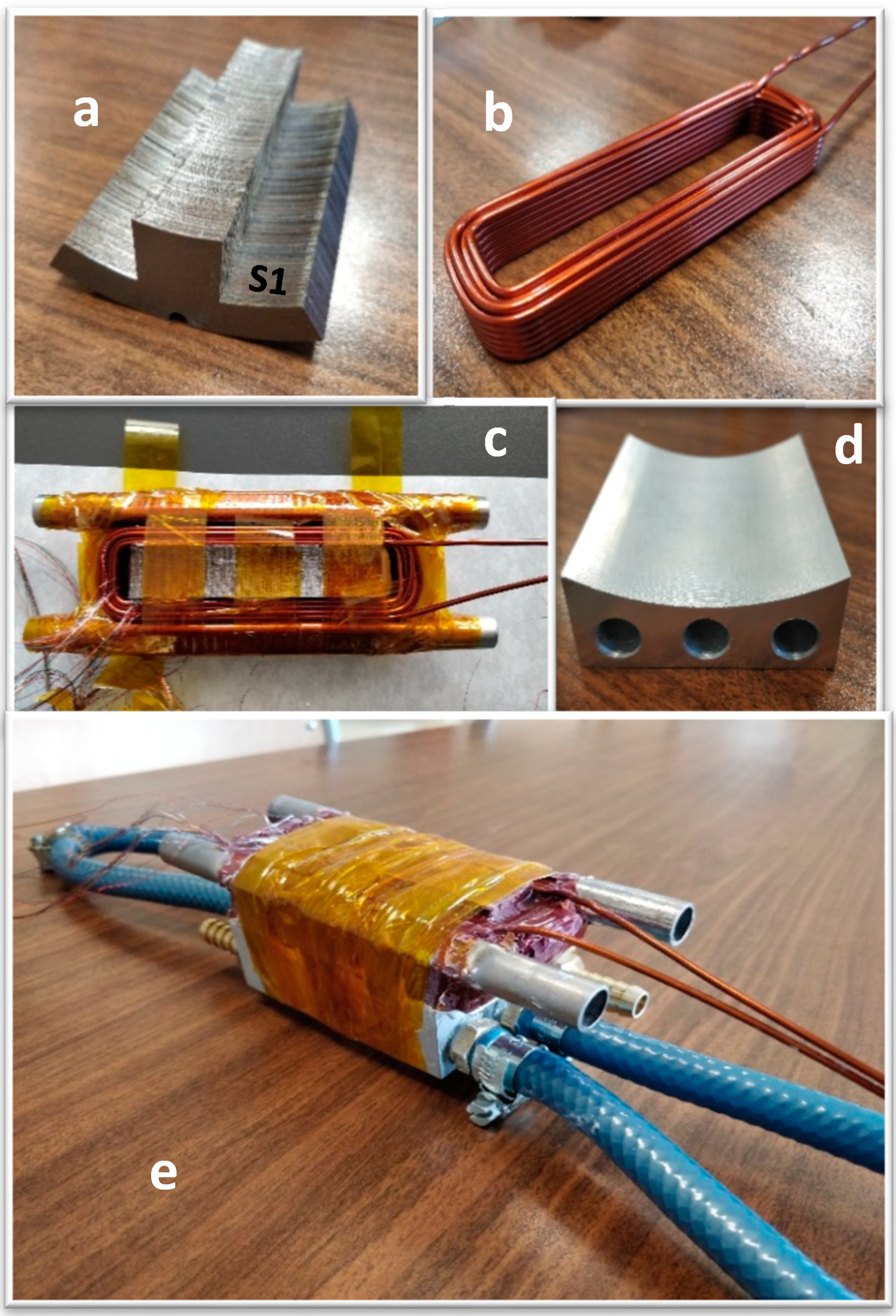
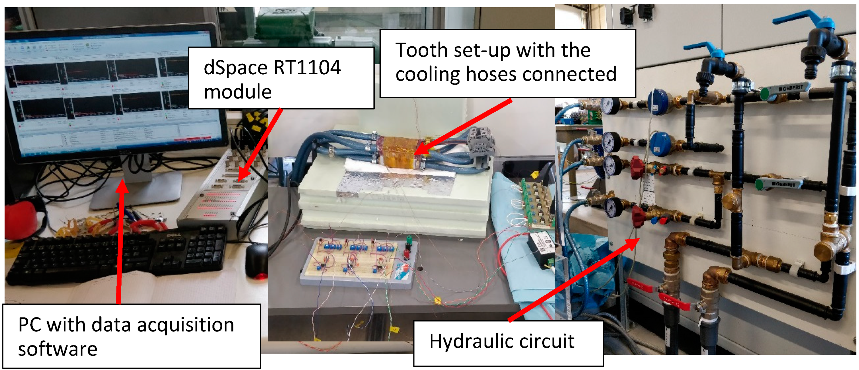
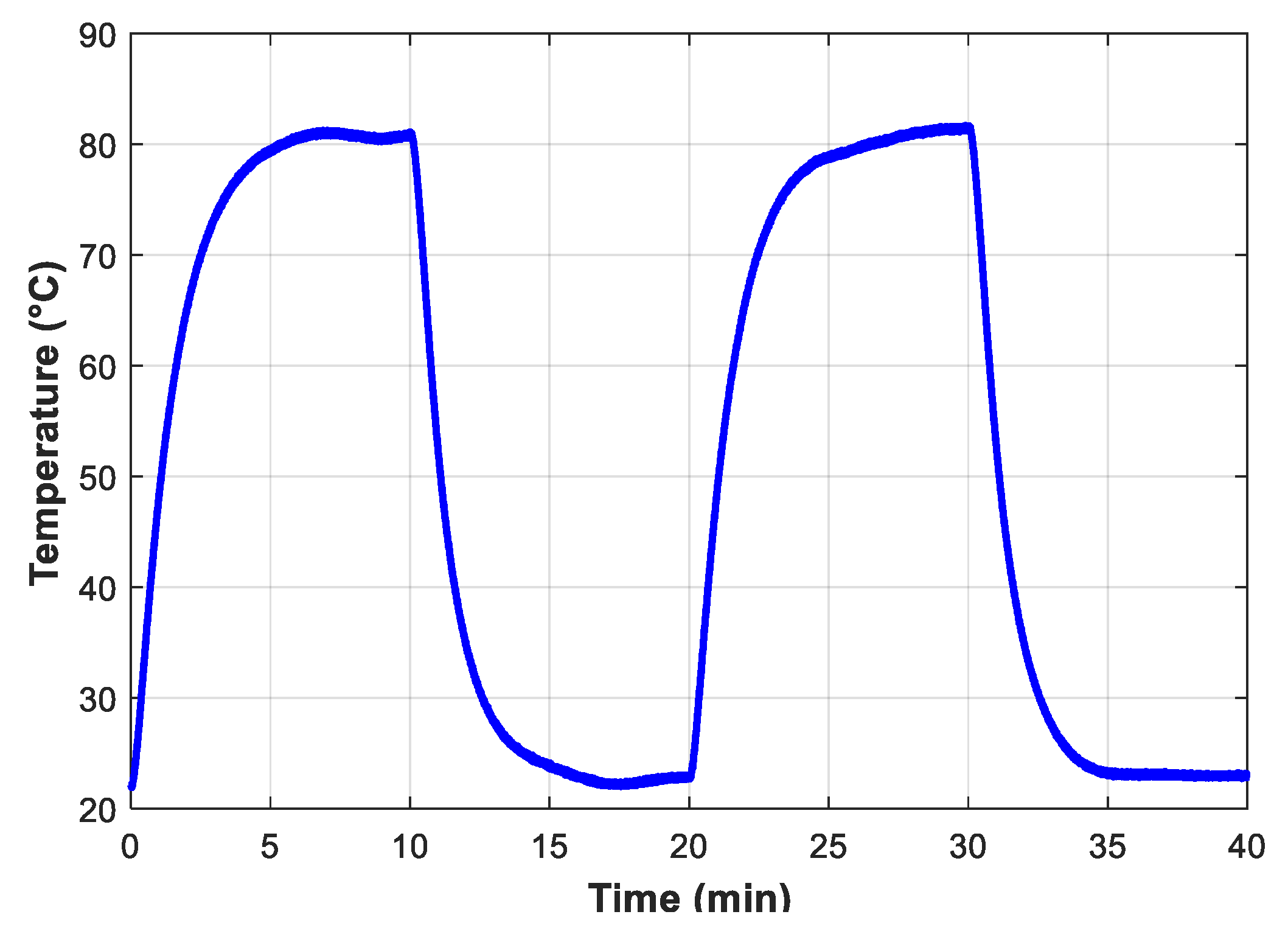
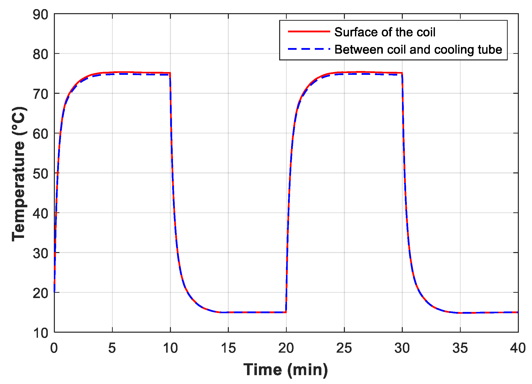
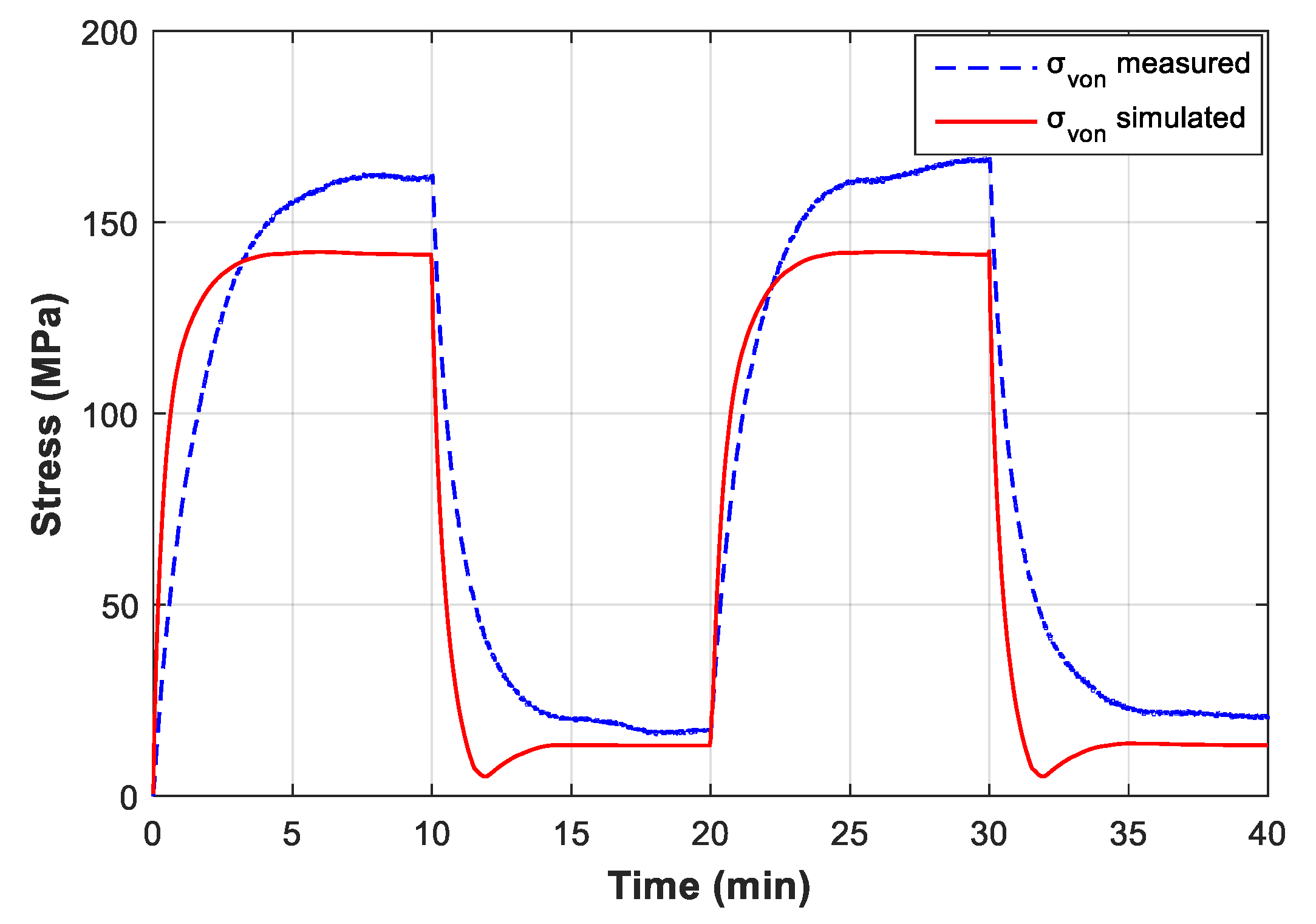
7. Validation Using Experiments

For the practical assessment of the stress induced in the stator winding of a machine with a certain cooling method employed, an experimental set-up was built. The set-up consists of a segmented stator winding, that is one stator tooth of a switched reluctance machine with concentrated winding. The stator tooth (Figure 14a), belongs to an existing switched reluctance machine, the parameters of which are given in Table 1. The winding is made as a form coil (Figure 14b with 25 turns of copper wire. The diameter of the copper wire is 1.9 mm. The form coil is placed over the tooth, as shown in Figure 14c, and then impregnated with epoxy resin. The set-up is equipped with cooling tubes as well as a water jacket for cooling purpose. The triangular cooling tubes with the dimensions listed in Table 3 are placed beside the winding before the winding is impregnated with epoxy resin. Henkel Loctite STYCAST 3050 epoxy is used as the epoxy resin. After the epoxy is cured, the water jacket (Figure 14d) is attached to the tooth set-up. The complete segmented stator winding set-up is shown in Figure 14e. This set-up can test water jacket cooling, direct-coil cooling using triangular tubes and combined water jacket and direct coil cooling techniques. However, here we only validate the combined water jacket and direct coil cooling technique.
To measure the stress, a strain gauge sensor (S1) (tolerance: 0.3%–0.35%) is installed on the iron surface at one end of the tooth as indicated in Figure 14a. Two PT100 temperature sensors (tolerance: ±0.05%) are installed in the set-up, one on the outer surface of the coil (T1) and the other between the coil and the cooling tube (T2). The segmented stator winding set-up is then placed in a thermally insulated box. The cooling hoses are connected to the hydraulic circuit. Both the direct coil cooling and the water jacket are supplied with water at 15 °C temperature, at a flow rate of 5 l/min. The winding of the tooth is then fed with dc voltage. The total power supplied to the set-up in the steady state was about 150 W. This power is equivalent to 900 W copper loss in the whole machine. The complete measurement set-up is shown in Figure 15, together with the hydraulic circuit used for cooling.
As the current is supplied in the copper wires, the temperature in the set-up starts to rise. At t = 10 min, the supply is switched off and the set-up is let to cool down. At t = 20 min, the supply is switched on again for another cycle. Figure 16 shows the temperature measured on the surface of the coil during the two cycles.
A numerical model with the geometry and the boundary conditions identical to the segmented stator winding set-up is developed in Comsol for validation purposes. The geometry of the new model is similar to the one shown in Figure 4, except that it does not have nomex paper between the tooth and the winding and liner between the winding and the cooling tube. Furthermore, the heat source in the new model is equivalent to about 900 W copper loss (identical to the measurement) in the machine, unlike 300 W used in the simulations in the previous sections. In addition, the possibility of an imperfect contact between the outer surface of the tooth segment and the water jacket has also been considered in this case. For this, a thermal interface resistance equivalent to a 0.037 mm air gap is taken into account while determining the equivalent convective heat transfer coefficient of the water jacket. The simulation procedure is the same as in the previous sections. First, the thermal model is solved to obtain the temperature distribution. In this case, the time-dependent temperature distribution is obtained. The heat source in the simulation was switched on and off at 10 min interval to replicate the measurement, and two thermal cycles were simulated. The temperature on the surface of the coil and between the coil and the cooling tube obtained from the simulation is shown in Figure 17. The temperature profiles demonstrate a close agreement with the measured temperature shown in Figure 16.
The strain gauge sensor installed in the set-up can measure stress in three directions in a—at 0°, 45° and 90° with respect to the axis where the sensor is installed. The von Mises stress is determined from these stress components and is shown together with the von-Mises stress obtained from the simulation in Figure 18. The results from both the simulation and the measurement have a reasonable agreement. The measured stress is about 20 MPa higher than the simulated stress in the steady state. One reason for this is that the measured temperature is about 6 °C higher than the simulated temperature in the steady state. The dependence of the stress with the temperature has already been validated in our previous study with both simulations and measurement [9].
The cyclic behavior of the stress is also validated by the measurement. Even if the stress level in the machine is well below the limit, such cyclic mechanical stress can eventually degrade the materials, for instance, the polymer coating of the wires and epoxy resins. This can be understood from Figure 1 in [7] which shows the number of cycles to failure of four different types of Polyamide-imide (PAI) coatings versus various cyclic stress levels.

8. Conclusions

In this paper, different methods typically used for the cooling of electrical machines have been compared with respect to the thermally induced mechanical stress in the windings. Two different configurations of water jacket cooling, two different configurations of direct coil cooling technique and the combined water jacket and direct coil cooling methods have been studied. The mechanical stress induced in the winding is the main focus in the paper. The simulations show that the use of direct coil cooling using triangular tubes has more advantages compared to the water jacket in terms of both temperature levels and stress levels. This is true both when it is used as the only cooling method in the machine and even when used in combination with the water jacket. An overview of the temperature and stress levels obtained from the simulations for all the cooling cases studied is presented in Table 4. A measurement set-up has been designed to validate the results from the numerical simulation. The set-up consists of a segmented stator winding set-up, which is excited by a dc power supply. The simulation results are in close agreement with the measured results.

Author Contributions

Conceptualization, B.S. and A.H.M.; Methodology, B.S. and J.N.; Software, B.S. and J.N.; Validation, B.S., and A.H.M.; Formal Analysis, B.S., A.H.M. and J.N.; Investigation, B.S.; Resources, B.S., A.H.M., and P.S.; Data Curation, B.S. and J.N.; Writing-Original Draft Preparation, B.S..; Writing-Review & Editing, A.H.M., J.N. and P.S.; Visualization, B.S.; Supervision, P.S. and M.D.P.; Project Administration, B.S. and P.S.; Funding Acquisition, P.S.

Funding

This research was supported by Flanders Make, in the framework of the Hipercool project.

Acknowledgments

The authors would like to thank Tony Boone for helping to design the segmented tooth set-up and Vincent Gevaert for making necessary laboratory arrangements.

Conflicts of Interest

The authors declare no conflict of interest.

References

  1. Bonnett, A.H.; Soukup, G.C. Cause and Analysis of Stator and Rotor Failures in Three-Phase Squirrel-Cage Induction Motors. IEEE Trans. Ind. Appl. 1992, 28, 921–937. [Google Scholar] [CrossRef]
  2. Zhang, Y.; McLoone, S.; Cao, W.; Qiu, F.; Gerada, C. Power Loss and Thermal Analysis of a MW High-Speed Permanent Magnet Synchronous Machine. IEEE Trans. Energy Convers. 2017, 32. [Google Scholar] [CrossRef]
  3. Pan, T.Y. Thermal Cycling Induced Plastic Deformation in Solder Joints—Part II: Accumulated Deformation in Through Hole Joints. IEEE Trans. Compon. HybridsManuf. Technol. 1991, 14, 824–832. [Google Scholar] [CrossRef]
  4. Seo, S.H.; Hwang, J.S.; Yang, J.M.; Hwang, W.J.; Song, J.Y.; Lee, W.J. Failure mechanism of copper through-silicon vias under biased thermal stress. Thin Solid Film 2013, 546, 14–17. [Google Scholar] [CrossRef]
  5. Tseng, H.K.; Wu, M.L. Electro-thermal-mechanical modeling of wire bonding failures in IGBT. In Proceedings of the 2013 8th International Microsystems, Packaging, Assembly and Circuits Technology Conference (IMPACT), Taipei, Taiwan, 22–25 October 2013; pp. 152–157. [Google Scholar] [CrossRef]
  6. Wood, J.W. Mechanical Stresses in Rotating Machines and Insulation Design Considerations. In Proceedings of the IEE Colloquium on Mechanical Influence on Electrical Insulation Performance, London, UK, 28 February 1995. [Google Scholar]
  7. Huang, Z.; Reinap, A.; Alaküla, M. Degradation and Fatigue of Epoxy Impregnated Traction Motors Due to Thermal and Thermal Induced Mechanical Stress—Part I: Thermal Mechanical Simulation of Single Wire due to Evenly Distributed Temperature. In Proceedings of the 8th IET International Conference on Power Electronics, Machines and Drives (PEMD), Glassgow, UK, 19–21 April 2016; pp. 1–5. [Google Scholar] [CrossRef]
  8. Huang, Z.; Reinap, A.; Alaküla, M. Degradation and Fatigue of Epoxy Impregnated Traction Motors Due to Thermal and Thermal Induced Mechanical Stress—Part II: Thermal Mechanical Simulation of Multiple Wires due to Evenly and Unevenly Distributed Temperature. In Proceedings of the 8th IET International Conference on Power Electronics, Machines and Drives (PEMD), Glassgow, UK, 19–21 April 2016; pp. 1–5. [Google Scholar] [CrossRef]
  9. Silwal, B.; Sergeant, P. Thermally Induced Mechanical Stress in the Stator Windings of Electrical Machines. Energies 2018, 11, 2113. [Google Scholar] [CrossRef]
  10. Nonneman, J.; Clarie, N.; Schlimpert, S.; Sergeant, P.; De Paepe, M. Advanced Lumped Parameter Model for Switched Reluctance Motors With High Performance Cooling. In Proceedings of the 16th International Heat Transfer Conference, Beijing, Chinga, 10–15 August 2018; pp. 1–9. [Google Scholar]
  11. Lindh, P.; Lindh, T.; Heikkinen, J.; Kurvinen, E.; De Legarra, M.S.; Maiza, M.M.I. Indirect water cooling system improvements for vehicle motor applications. In Proceedings of the 9th International Conference on Compatibility and Power Electronics, Costa da Caparica, Portugal, 24–26 June 2015; pp. 276–280. [Google Scholar] [CrossRef]
  12. Zhang, B.; Qu, R.; Fan, X.; Wang, J. Thermal and mechanical optimization of water jacket of permanent magnet synchronous machines for EV application. In Proceedings of the IEEE International Electric Machines and Drives Conference (IEMDC 2015), Coeur d’Alene, ID, USA, 10–13 May 2015; pp. 1329–1335. [Google Scholar] [CrossRef]
  13. Yang, Y.; Bilgin, B.; Kasprzak, M.; Nalakath, S.; Sadek, H.; Preindl, M.; Cotton, J.; Schofield, N.; Emadi, A. Thermal management of electric machines. IET Electr. Syst. Transp. 2017, 7, 104–116. [Google Scholar] [CrossRef] [Green Version]
  14. Liu, Z.; Winter, T.; Schier, M. Comparison of Thermal Performance Between Direct CoilCcooling and Water Jacket Cooling for Electric Traction Motor based on Lumped Parameter Thermal Network and Experimentation. In Proceedings of the EVS28 International Electric Vechicle Symposium and Exhibition, Goyang, Korea, 3–6 May 2015; pp. 1–8. [Google Scholar]
  15. Tighe, C.; Gerada, C.; Pickering, S. Assessment of cooling methods for increased power density in electrical machines. In Proceedings of the 22nd International Conference on Electrical Machines ICEM, Lausanne, Switzerland, 4–7 September 2016; pp. 2626–2632. [Google Scholar] [CrossRef]
  16. Reinap, A.; Márquez-Fernández, F.J.; Andersson, R.; Hogmark, C.; Alakula, M.; Göransson, A. Heat transfer analysis of a traction machine with directly cooled laminated windings. In Proceedings of the 2014 4th International Electric Drives Production Conference EDPC, Nuremburg, Germany, 30 September–1 October 2014. [Google Scholar] [CrossRef]
  17. Micallef, C.; Pickering, S.J.; Simmons, K.A.; Bradley, K.J. Improved cooling in the end region of a strip-wound totally enclosed fan-cooled induction electric machine. IEEE Trans. Ind. Electron. 2008, 55, 3517–3524. [Google Scholar] [CrossRef]
  18. Micallef, C.; Pickering, S.J.; Simmons, K.A.; Bradley, K.J. An alternative cooling arrangement for the end region of a totally enclosed fan cooled (TEFC) induction motor. In Proceedings of the 4th IET Conference on Power Electronics, Machines and Drives PEMD, York, UK, 2–4 April 2008; pp. 305–309. [CrossRef]
  19. Popescu, M.; Staton, D.A.; Boglietti, A.; Cavagnino, A.; Hawkins, D.; Goss, J. Modern Heat Extraction Systems for Power Traction Machines—A Review. IEEE Trans. Ind. Appl. 2016, 52, 2167–2175. [Google Scholar] [CrossRef]
  20. Lindh, P.M.; Petrov, I.; Semken, R.S.; Niemela, M.; Pyrhonen, J.J.; Aarniovuori, L.; Vaimann, T.; Kallaste, A. Direct liquid cooling in low-power electrical machines: Proof-of-concept. IEEE Trans. Energy Convers. 2016, 31, 1257–1266. [Google Scholar] [CrossRef]
  21. Rhebergen, C.; Bilgin, B.; Emadi, A.; Rowan, E.; Lo, J. Enhancement of electric motor thermal management through axial cooling methods: A materials approach. In Proceedings of the IEEE Energy Conversion Congress and Exposition (ECCE), Montreal, QC, Canada, 20–24 September 2015; pp. 5682–5688. [Google Scholar] [CrossRef]
  22. Hewitt, G.; Barbosa, J. Heat Exchanger Design Handbook (Vol. 98); Begell House: Danbury, CT, USA, 2008. [Google Scholar]
  23. Shah, R.K.; Sekulic, D.P. Fundamentals of Heat Exchanger Design; Wiley & Sons: Hoboken, NJ, USA, 2003. [Google Scholar]
Figure 1. One of the two water jackets (WJ2) used in the study and the flow path of the coolant. It has two main channels with each channel having further two channels in series. (a) prototype; (b) coolant flowpath.
Energies 12 01967 g001
Figure 2. Two configurations of the direct coil cooling technique studied in the paper: DCC1 (left) and DCC2 (right).
Energies 12 01967 g002
Figure 3. 2D cross-section of the machine, a stator segment of which is used as the test case in this study.
Energies 12 01967 g003
Figure 4. Boundary conditions for thermal (left) and mechanical simulations (right).
Energies 12 01967 g004
Figure 5. Heat flow path for different cooling cases: (a) water jacket cooling WJ1 and WJ2; (b) Direct coil cooling DCC1; (c) Direct coil cooling DCC2 and; (d) combined cooling WJ(x) + DCC2.
Energies 12 01967 g005
Figure 6. Temperature distribution for WJ1 (left) and WJ2 (right).
Energies 12 01967 g006
Figure 7. Temperature distribution for DCC1 (left) and DCC2 (right).
Energies 12 01967 g007
Figure 8. Temperature distribution for WJ1 + DCC1 (left) and WJ2 + DCC2 (right).
Energies 12 01967 g008
Figure 9. Resulting stress distribution for WJ1 (a,c,e) and WJ2 (b,d,f). (a,b) show the overall stress distribution; (c,d) show the stress in the copper coils; (e,f) show the stress in three different positions along the axial length of the machine.
Energies 12 01967 g009
Figure 10. Resulting stress distribution for DCC1 and DCC2. (a,b) show the overall stress distribution; (c,d) show the stress in the copper coils; (e,f) show the stress in three different positions along the axial length of the machine.
Energies 12 01967 g010aEnergies 12 01967 g010b
Figure 11. Resulting stress distribution for WJ1 + DCC1 and WJ2 + DCC2. (a,b) show the overall stress distribution; (c,d) show the stress in the copper coils; (e,f) show the stress in three different positions along the axial length of the machine.
Energies 12 01967 g011aEnergies 12 01967 g011b
Figure 12. Maximum stress calculated in the copper wires as a function of the coefficient of thermal expansion of epoxy.
Energies 12 01967 g012
Figure 13. Average stress in the copper wires as a function of the coefficient of thermal expansion of epoxy.
Energies 12 01967 g013
Figure 14. Construction of the segmented stator winding set-up used for the validation of the numerical results: (a) one tooth segment of the stator of a SR machine; (b) form coil used as the winding; (c) form coil placed on the tooth along with two triangular tubes for direct coil cooling, ready to be impregnated with epoxy resin; (d) water jacket for the set-up; (e) the epoxy impregnated segmented stator winding set-up together with the water jacket.
Energies 12 01967 g014
Figure 15. Complete measurement set-up and the hydraulic circuit used for cooling.
Energies 12 01967 g015
Figure 16. Temperature measured on the surface of the coil by Sensor T1 located on the outer surface of the coil.
Energies 12 01967 g016
Figure 17. Temperature profiles obtained from the simulation.
Energies 12 01967 g017
Figure 18. Comparison of the von-Mises stress obtained from the simulation and measurement.
Energies 12 01967 g018
Table 1. Geometrical dimensions of the machine.
ParametersValue
Number of stator poles6
Outer diameter of stator (mm)120
Inner diameter of stator yoke (mm)98
Thickness of the tooth (mm)17.5
Stack length (mm)80
Number of turns per coil25
Table 2. Material properties used in the simulations.
PropertiesCopperCoreEpoxySteel Tube
Thermal conductivity (W/m·K)40022.2 (radial)0.2114
4.9 (axial)
Density (kg/m3)8960765011807850
Heat capacity at constant pressure (J/kg·K)385440440475
Coefficient of thermal expansion (1/K)18 × 10−612 × 10−650 × 10−612 × 10−6
Young’s modulus (Pa)1.10 × 10112 × 10113.5 × 1092.05 × 1011
Poisson’s ratio0.350.290.340.28
Table 3. Properties of cooling methods.
Water JacketDirect Coil Cooling
ParametersWJ1WJ2DCC1DCC2
Channel shape (-)circularrectangulartriangulartriangular
Channel (hydraulic) diameter (mm)46.77.05.7
Channel height (mm)-512.910.3
Channel width(mm)-1014.311.9
Channel length (mm)802128080
CoolantWaterWaterATFWater
Inlet Temperature (°C)15151515
Flow rate (l/min)5555
Convective heat transfer coefficient (W/m2K)294533908979663
Table 4. Overview of the temperature and stress levels obtained from simulations.
WJ1WJ2DCC1DCC2WJ1 + DCC1WJ2 + DCC2
Maximum temperature (°C)115114108806461
Maximum stress in the wires (MPa)14414393876870
Average stress in the wires (MPa)878647434242

