Article

Disc Thickness and Spacing Distance Impacts on Flow Characteristics of Multichannel Tesla Turbines

Shaanxi Engineering Laboratory of Turbomachinery and Power Equipment, Institute of Turbomachinery, School of Energy and Power Engineering, Xi’an Jiaotong University, Xi’an 710049, China
*
Author to whom correspondence should be addressed.
Energies 2019, 12(1), 44; https://doi.org/10.3390/en12010044
Submission received: 9 November 2018 / Revised: 14 December 2018 / Accepted: 20 December 2018 / Published: 24 December 2018
(This article belongs to the Special Issue Engineering Fluid Dynamics 2018)

Abstract

:
Tesla turbines are a kind of unconventional bladeless turbines, which utilize the viscosity of working fluid to rotate the rotor and realize energy conversion. They offer an attractive substitution for small and micro conventional bladed turbines due to two major advantages. In this study, the effects of two influential geometrical parameters, disc thickness and disc spacing distance, on the aerodynamic performance and flow characteristics for two kinds of multichannel Tesla turbines (one-to-one turbine and one-to-many turbine) were investigated and analyzed numerically. The results show that, with increasing disc thickness, the isentropic efficiency of the one-to-one turbine decreases a little and that of the one-to-many turbine reduces significantly. For example, for turbine cases with 0.5 mm disc spacing distance, the former drops less than 7% and the latter decreases by about 45% of their original values as disc thickness increases from 1 mm to 2 mm. With increasing disc spacing distance, the isentropic efficiency of both kinds of turbines increases first and then decreases, and an optimal value and a high efficiency range exist to make the isentropic efficiency reach its maximum and maintain at a high level, respectively. The optimal disc spacing distance for the one-to-one turbine is less than that for the one-to-many turbine (0.5 mm and 1 mm, respectively, for turbine cases with disc thickness of 1 mm). To sum up, for designing a multichannel Tesla turbine, the disc spacing distance should be among its high efficiency range, and the determination of disc thickness should be balanced between its impacts on the aerodynamic performance and mechanical stress.

1. Introduction

In the last two decades, one of the interests is to develop small-scale turbomachinery due to market demands driving and manufacture techniques making progress [1], which is mainly applied to small power generation unit, such as distributed energy systems using low-grade energy and increasing energy utilization efficiency. In addition, small-scale turbomachinery is also applied as the mobile or small power device, which can be used in unmanned aircraft, miniaturized radio-controlled vehicles [2,3], and so on.
Several research groups designed, manufactured and experimented some small or micro gas turbines to study their feasibility and effectiveness [4,5,6,7,8,9]. These studies show that two major problems are faced when conventional turbines are scaled down. One is the rapidly increasing rotational speed, and the other is the significantly decreasing flow efficiency. Moreover, Brayton cycle system cannot be realized when the flow efficiency of conventional turbines goes down to a certain amount due to their microminiaturization [10]. However, a Tesla turbine is considered as one of the best alternatives [11].
In 1913, the first Tesla turbine was designed, manufactured and patented by the famous scholar Nikola Tesla [12]. It is an unconventional bladeless turbomachinery, which uses the viscous stress acting on rotating disc walls to drag the rotor to rotate, as shown in Figure 1. The rotor of Tesla turbines is composed by several flat, parallel, rigid, co-rotating discs, which are placed closely and mounted on a central shaft. The narrow spaces between the adjacent discs are disc channels. In Tesla turbines, the working fluid accelerates in nozzles or volute and obtains its highest flow velocity at the stator outlet; then injects into the disc channels nearly tangentially; and finally flows spirally towards the disc holes or slots around the shaft.
During 1913–1950, little research was conducted on Tesla turbines due to the invention of gas turbines and its high efficiency. Thereafter, the theoretical and experimental analysis on Tesla turbines has been restarted due to its advantages; for example, it is simple to manufacture and maintain with low cost and it can use kinds of working fluid [13,14,15,16]. However, the study progress of Tesla turbines was still slow. In the last two decades, much research on Tesla turbines has been reported using not only theoretical and experimental methods but also numerical simulations due to the rapid development of computational fluid dynamics (CFD) and advanced computer techniques.
According to the inlet geometry, Tesla turbines are classified into two types: voluted Tesla turbine and nozzled Tesla turbine. There are few reports on the voluted Tesla turbine. The flow characteristics and loss mechanism of voluted Tesla turbines were investigated using experimental and numerical methods [17]. The results show that the theoretical limit of the isentropic efficiency is about 40%, if the parasitic losses, mainly including bearing loss, viscous loss on end walls, and eddy loss in the volute, can be minimized.
The main focus of Tesla turbines is on investigating flow characteristics in nozzled Tesla turbines. A one-dimensional analysis method of flow field in the disc channel is proposed with some hypotheses, and the model agrees well with previous experimental performance data [18]. Sengupta and Guha formulated a mathematical theory by simplifying the Navier–Stokes equations using a magnitude analysis method, which can assess the turbine performance [19,20,21]. Talluri et al. developed a new method for designing of a Tesla turbine for Organic Rankine Cycle (ORC) applications, in which almost all losses are considered using real gas physical properties [22]. It can calculate the aerodynamic performance of the multichannel Tesla turbine; however, the results have not been validated by numerical and experimental analysis. To sum up, most theoretical analysis can only be applied to one channel Tesla turbines, in which the influence of disc thickness has not been taken into account yet.
Some researchers investigated the total aerodynamic performance and detailed flow fields using experimental method. The research group of Guha set up a test rig of Tesla turbines, and put forward several methods for measuring power [23]. In addition, they improved the inlet and nozzle to enhance the turbine efficiency [24]. Schosser et al. designed and set up a test rig to reveal the detailed flow field in the disc spacing of one channel Tesla turbine using 3D tomographic Particle Image Velocimetry (PIV) and Particle Tracking Velocimetry (PTV) measurements, however its rotational speed is restricted because of the mechanical stress [25]. From the above research, the detailed flow field in multichannel Tesla turbines cannot be investigated experimentally.
The complicated turbine model cannot be analyzed theoretically, although it can be simulated by CFD method to reveal the detailed flow characteristics. The effects of some parameters, such as the rotational speed and nozzle number, have been studied for a Tesla turbine with a low-boiling medium [11,26]. The effects of disc spacing distance and rotational speed on a Tesla turbine were analyzed numerically by our research group, and the results show that an optimal value of both parameters exists for the turbine to obtain its highest efficiency, respectively [27,28,29]. The flow fields in the disc channel of one channel Tesla turbine (no stator) with different inlet conditions, including flow coefficient and inlet geometries, were simulated numerically; the efficiency decreases dramatically with increasing flow coefficient, and the inlet non-uniformity is also a factor that makes turbine efficiency decrease [30]. Sengupta et al. studied the influence of four parameters, namely the nozzle number, disc thickness, rotational speed and nozzle-rotor radial clearance, on the performance of a Tesla turbine, and the results show that in the turbine design, thin discs with flat disc tip edge, more nuzzles and an optimal radial clearance are suggested [31].
In the authors’ previous study, the nozzled multichannel Tesla turbine is classified into two categories according to nozzle geometry: one nozzle channel to one disc channel (one-to-one Tesla turbines) and one nozzle channel to several disc channels (one-to-many Tesla turbines), as shown in Figure 2 [29]. The one-to-one Tesla turbine and the one-to-many turbine with the same geometry operating under the same conditions were studied numerically and the only difference between two kinds of Tesla turbines is their nozzle geometries. The objective was to reveal and compare their fluid dynamic, and the results show that the flow mechanism of the two Tesla turbines are totally different.
For multichannel Tesla turbines, the affecting factors include the geometrical parameters (such as nozzle number, nozzle geometry, disc outer diameter, disc spacing distance and disc thickness) and operating parameters (such as rotational speed mass flow rate and turbine pressure ratio). The above reference review shows that the influence of most affecting parameters has been investigated, although some research is on one channel Tesla turbine. However, up to now, few studies have been conducted on the impacts of disc thickness and disc spacing distance on the performance of multichannel Tesla turbines. The effect of disc thickness is studied in Ref. [31], but only the flow in the nozzle-rotor chamber and the rotor are included in numerical calculations. In addition, it has been analyzed experimentally for the one-to-many turbine, while, for the one-to-one turbine, its influence and the fluid mechanism have not been investigated [32].
The impacts of disc spacing distance on the one channel Tesla turbine were analyzed by our group, and the results show that an optimal disc spacing distance exists to enable the Tesla turbine to obtain its best performance [28]. In the turbine with narrower disc spacing distance, two boundary layers on two disc walls overlap, resulting in a decrease in frictional force and torque; in the turbine with wider disc spacing distance, more working fluid outside the boundary layer flows out of the disc channels resulting in less momentum exchange to drive a rotor. Because disc thickness has to be taken into consideration in multichannel Tesla turbines, the influence of disc spacing distance on flow fields must be different from that in one channel Tesla turbines.
In this paper, two kinds of multichannel Tesla turbines (one-to-one turbines and one-to-many turbines) with different disc spacing distance and disc thickness are simulated numerically to investigate their influence on the aerodynamic performance and flow characteristics. This paper provides theoretical and engineering reference for designing a multichannel Tesla turbine.

2. Numerical Approach

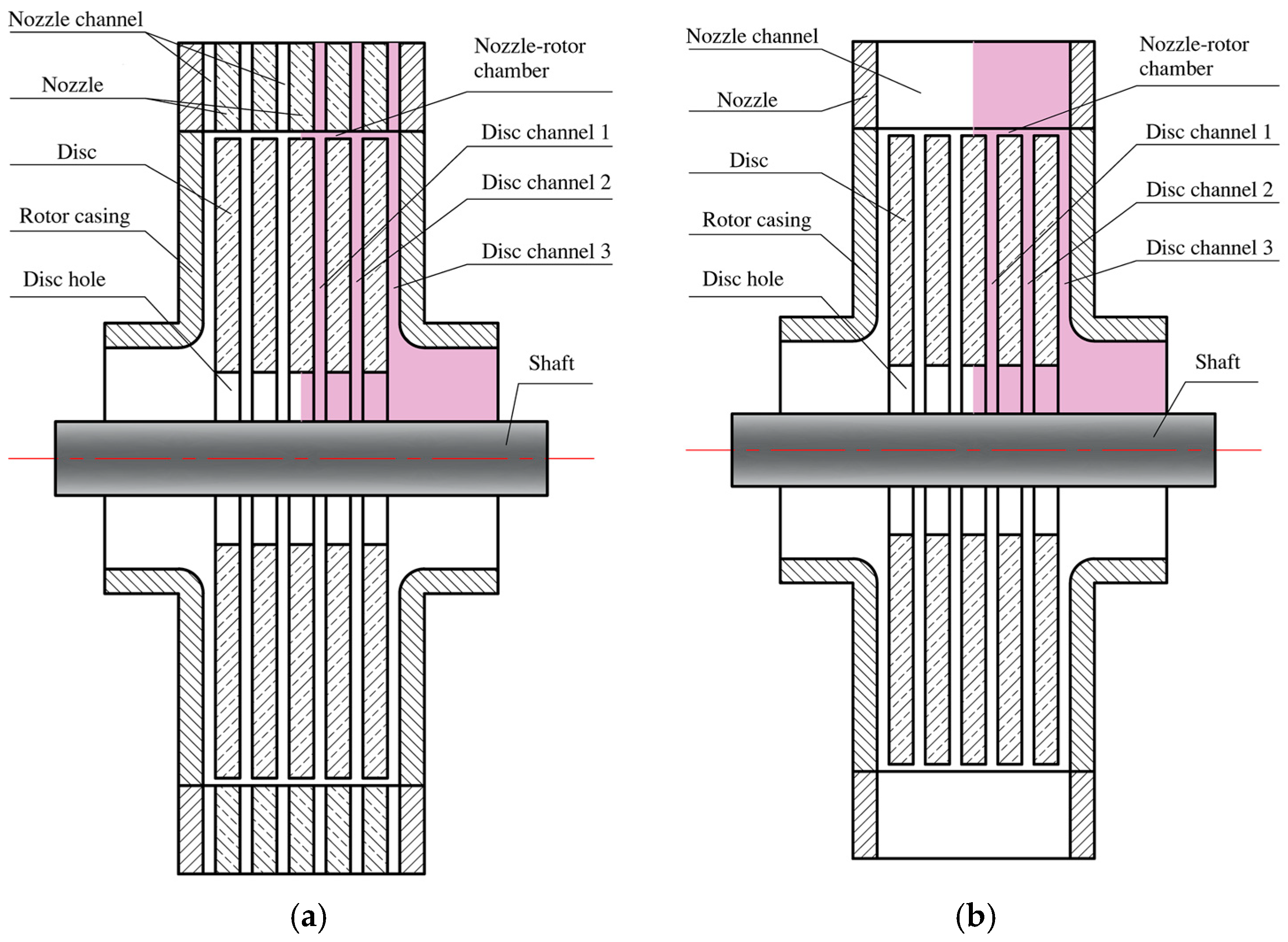
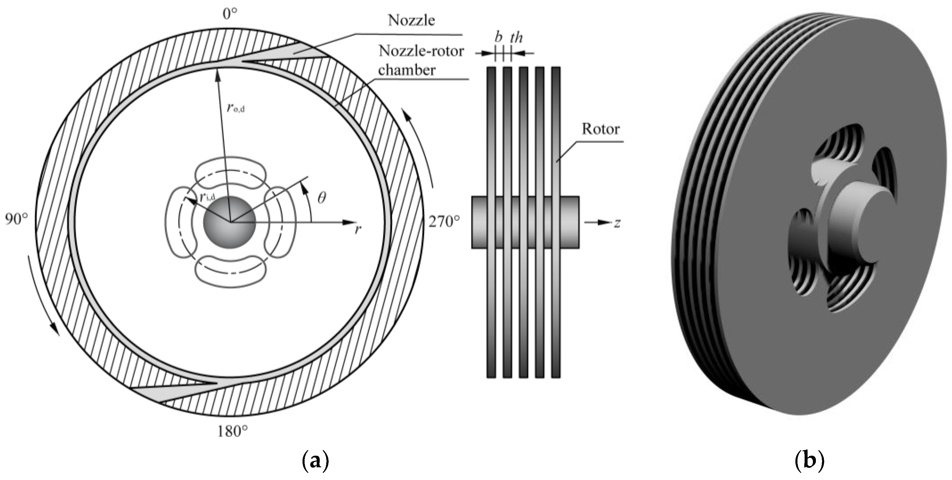
2.1. Geometry Model and Boundary Conditions

In this study, two groups of multichannel Tesla turbines were calculated numerically. One group is the one-to-one Tesla turbine, and the other is the one-to-many Tesla turbine. Each group has six cases of Tesla turbines, and the parameters of disc spacing distance and disc thickness are given in Table 1, in which the case is named as “disc thickness-disc spacing distance”. In this research, the working fluid is compressed air.
Each turbine case consists of five discs and six disc channels. The other geometrical parameters and aerodynamic parameters are all the same for the two groups of the Tesla turbine, which are the same as those in the authors’ previous study [29] (Table 2).
To save computing time and resources, the calculation domain was reduced based on a rotational symmetry and a symmetry about a middle plane that is normal to the axis, which finally became a quarter of the whole turbine. It is shown in Figure 2 with red color.
The boundary conditions are given in Table 2. In addition, because of the calculation domain reduction, the symmetry and rotational periodicity boundary conditions were set up at corresponding surfaces. The adiabatic and no-slip boundary condition was adopted for all walls. The frozen rotor method was applied to deal with the rotor-stator interface.

2.2. Numerical Solver and Mesh Sensitivity

In this research, all numerical calculations were conducted using commercial software ANSYS CFX (ANSYS Inc., Canonsburg, PA, USA), in which the Reynolds Averaged Navier–Stokes (RANS) equations in the calculation domain were solved for turbulent flow. The RANS equation groups are as follows.
Continuity equation:
ρ t + x j ( ρ U j ) = 0
Momentum equations:
ρ U i t + x j ( ρ U i U j ) = p x i + x j ( τ i j ρ u i u j ¯ ) + S M
Energy equations:
( ρ h t o t ) t p t + x j ( ρ U j h t o t ) = x j ( λ T x j ρ u j h ¯ ) + x j [ U i ( τ i j ρ u i u j ¯ ) ] + S E
in which x j are coordinates in three directions, U j are average velocity in three directions, p is the static pressure, T is the temperature, ρ is the density, and τ is the molecular stress tensor.
In Equations (2) and (3), S M and S E are source terms, ρ u i u j ¯ are the Reynolds stresses, ρ u j h ¯ is an additional turbulence flux term, x j [ U i ( τ i j ρ u i u j ¯ ) ] represents the viscous work term. h t o t is the mean total enthalpy, h is the static enthalpy, and h t o t = h + U i U j / 2 + k , where k is the turbulent kinetic energy and k = u i 2 ¯ / 2 .
In addition, the density can be solved according to the state equation for ideal air,
ρ = p abs / R T
where p abs is the absolute pressure and R is the specific gas constant of air.
According to the above discussion, it can be found that RANS equations are not closed due to two additional terms, which are Reynolds stress and Reynolds flux. Therefore, some turbulence models in ANSYS CFX are provided to calculate turbulent flow.
For Tesla turbines, the detailed experimental data cannot be found in public references, therefore the flow model verification could not be conducted. The critical Reynolds number for the plane Poiseuille flow is about 1000 [33], and is defined by the half disc spacing distance and the average velocity in Tesla turbines. In most Tesla turbines, the Reynolds number is always above the critical values, and the minimum Reynolds number was about 1500 in our computational cases. Therefore, the Shear Stress Transport (SST) turbulence model was adopted in this research, which is also used in numerical research by other researchers [11,25,26].
SST turbulence model is a kind of eddy viscosity model, and, according to eddy viscosity hypothesis, the Reynolds stresses are considered to be proportional to mean velocity gradients. They can be expressed as follows.
ρ u i u j ¯ = μ t ( U i x j + U j x i ) 2 3 δ i j ( ρ k + μ t U k x k )
where μ t is the eddy viscosity.
In addition, the Reynolds fluxes of a scalar is stated as a linear relationship to the mean scalar gradient based on the eddy diffusivity hypothesis:
ρ u i ϕ ¯ = Γ t Φ x i
where ρ u i ϕ ¯ is the Reynolds flux of a scalar Φ , Γ t is the eddy diffusivity, written as Γ t = μ t / Pr t , and Pr t is the turbulent Prandtl number.
Equations (5) and (6) give expressions of turbulent fluctuations as functions of the mean variables when the turbulent viscosity is known. In ANSYS CFX solver, SST turbulence model, which derives from the k ε and k ω turbulence models, uses this variable and expresses the turbulent viscosity as,
μ t = ρ k ω
where ω is turbulent frequency.
The Reynolds averaged transport equations for k and ω in SST turbulence model are as follows.
( ρ ω ) t + x j ( ρ U j ω ) = x j [ ( μ + μ t σ ω 3 ) ω x j ] + ( 1 F 1 ) 2 ρ 1 σ ω 2 ω k x j ω x j + α 3 ω k P k β 3 ρ ω 2 + P k b
( ρ k ) t + x j ( ρ U j   k ) = x j [ ( μ + μ t σ k 2 ) k x j ] + P k β ρ k ω + P k b
For the detailed coefficients in Equations (8) and (9), refer to Ref. [34]. Up to now, the RANS equations are closed, and can be solved to obtain the turbulent flow fields.
For all numerical simulations in this research, spatial discretization for the above flow governing equations was conducted with high-resolution second-order central difference scheme and time discretization was with second-order backward Euler scheme. In addition, an empirical automatic wall function was adopted to guarantee the solution accuracy. The accuracy of second order was obtained in all numerical simulations. In addition, the y+ should be less than 2 for all walls as the SST turbulence model requires.
In this study, a structured grid was generated for fluid domain, using ANSYS mesh generation software ICEM CFD (ANSYS Inc., Canonsburg, PA, USA). The mesh independence analysis for the one-to-many turbine Case 1-0.5 was conducted to ensure the accuracy of the results.
Three sets of mesh for this turbine were generated and the detailed information are given in Table 3. The N-R chamber stands for the chamber between the nozzle and the rotor.
The aerodynamic performance parameters and their relative variation values (based on the results of Case 3) are given in Table 4. The isentropic efficiency η is defined as the actual shaft power P divided by the isentropic power across the whole turbine m Δ h isen , as follows:
η = P m Δ h isen = M Ω m c p T nt [ 1 ( p i / p nt ) ( γ 1 ) / γ ]
where P equals the whole torque M multiplied by the angular speed of the rotor Ω . c p and γ are the physical properties of the working fluid, which are specific heat at constant pressure and the specific heat ratio. The subscript “nt” represent the total parameters at the turbine inlet, while “i” indicates the static parameter at the turbine outlet.
Figure 3 presents the Mach number contours on the mid-section of DC1 (“DC” is short for “disc channel”) for the one-to-many turbine Case 1-0.5 with three different node cases. The detailed locations of the three DCs are indicated in Figure 2. Note that DC1 and DC2 each consists of two rotating disc walls, and DC3 has one rotating disc wall and one motionless casing wall.
Table 4 indicates that the variation value of each aerodynamic performance decreases with node number. Figure 3 shows that the Mach number distribution for each case is similar, but the difference between Cases 2 and 3 is much less than that between Cases 1 and 2. To sum up, the results of Case 2 fulfill the requirements for mesh independence, therefore the mesh of Case 2 was applied for the this turbine in numerical simulations. Moreover, for other turbine cases with different geometry, the grid distribution changes accordingly to get a reliable result.

3. Results and Discussions

3.1. Total Aerodynamic Performance of Two Kinds of Multichannel Tesla Turbines

Two kinds of multichannel Tesla turbines with disc thickness of 1 mm and 2 mm were calculated numerically, respectively. It is obvious that, if the disc thickness is too large, the air flowing into disc channels will be more difficult, therefore, the aerodynamic performance becomes worse. However, the disc thickness should not be too small, which is mainly confined to its mechanical stress and processing problem. As disc thickness decreases, the stiffness of the discs decreases rapidly, and accordingly the mechanical stress increases, which should be lower than material allowable stress. Previous study on the computational solid mechanical (CSM) analysis indicates that the disc thickness should not be less than 1 mm for the Tesla turbine with disc outer diameter of 100 mm.

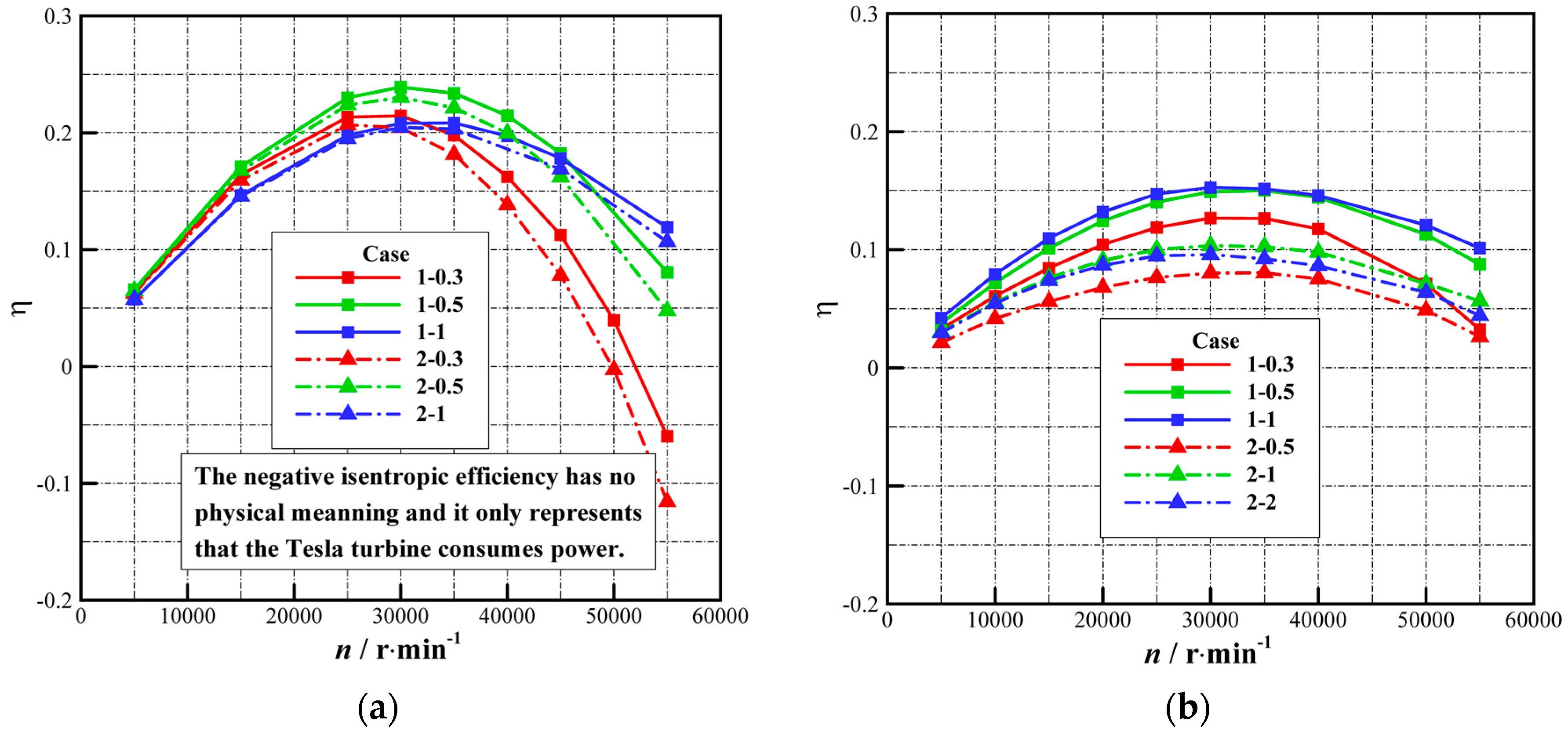
3.1.1. Isentropic Efficiency

Figure 4 shows the variation curves of the isentropic efficiency for each turbine case with the rotational speed for the two kinds of multichannel Tesla turbines. In Figure 4, note that the negative isentropic efficiency has no physical meaning and only indicates that under this condition the Tesla turbine consumes external energy without power outputting. It can be seen that the isentropic efficiency of the one-to-one turbine is much higher than that of the one-to-many Tesla turbine, and it changes much faster with rotational speed.
For the one-to-one turbine, the isentropic efficiency of the turbine cases with same disc spacing distance but different disc thickness is almost equal, although the turbine cases with smaller disc thickness are slightly more efficient, which is more obvious at higher rotational speeds. For example, the isentropic efficiency of Case 2-0.5 has a less than 7% reduction of that of Case 1-0.5 at all rotational speeds lower than 45,000 r/min. The turbine case with disc spacing distance of 0.5 mm obtains the highest efficiency at lower rotational speeds. That is, an optimal disc spacing distance for the one-to-one multichannel Tesla turbine exists to obtain its best performance, which is in accordance with that for one channel Tesla turbines [28]. In fact, a high efficiency range of disc spacing distance exists, among which the isentropic efficiency can remain at a high level. However, the turbine with disc spacing distance of 1 mm performs best at higher rotational speeds, because the isentropic efficiency changes more rapidly with rotational speed for the turbine case with narrower disc spacing distance. It can be predicted that an optimal disc spacing distance must exist at higher rotational speeds, which must be higher than 0.5 mm.
For the one-to-many turbine, obviously, the isentropic efficiency of the turbine cases with greater disc thickness is much lower than that of the cases with smaller disc thickness, which agrees well with the experimental results in Ref. [32]. In detail, the turbine isentropic efficiency of Case 2-0.5 is about 55% of that of Case 1-0.5. Meanwhile, the one-to-many turbine also has an optimal disc spacing distance.
To sum up, for designing multichannel Tesla turbines, a one-to-one Tesla turbine is recommended. Moreover, the disc spacing distance should be in its high efficiency range, and the disc thickness should be as small as possible while satisfying the requirement of allowable material stress. Usually, the disc thickness can be determined by the results of CSM, and it should be larger than 1 mm for discs of 100 mm diameter.

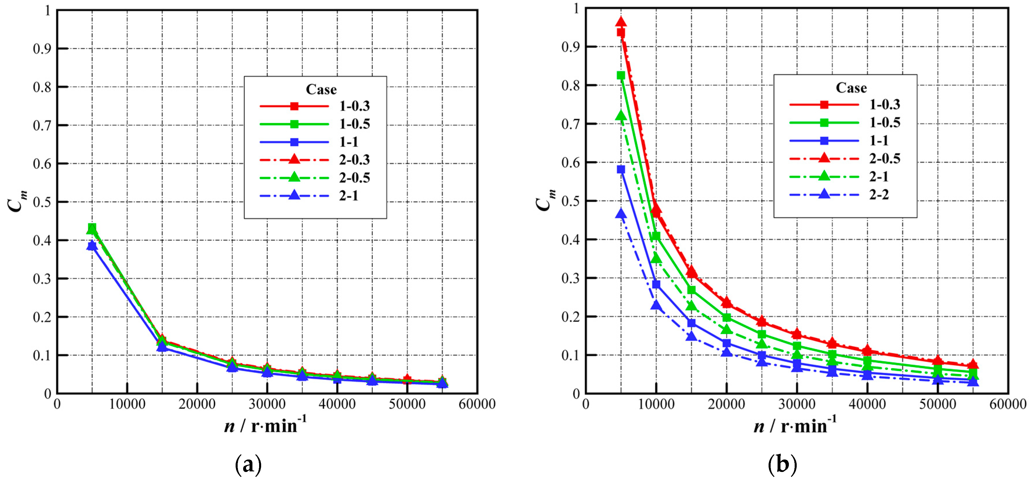
3.1.2. Flow Coefficient

Figure 5 presents the curves of the flow coefficient for each turbine case versus the rotational speed. The flow coefficient C m is defined as:
C m = v o , d Ω r o , d = m 2 π ρ o , d Ω b r o , d 2
where v o , d and ω r o , d represent the average radial velocity and the disc rotational linear velocity at the rotor inlet, respectively.
The flow coefficient of the one-to-one Tesla turbine is much less than that of the one-to-many turbine with same disc spacing distance and disc thickness (Figure 5). In detail, for turbine Case 1-0.5, that of the one-to-many is nearly double that of the one-to-one turbine. Compared to the one-to-one turbine, when the operating parameters and other geometrical parameters are given, the mass flow rate of the one-to-many turbine is much higher due to much larger nozzle throat area (for Case 1-0.5, the one-to-many turbine is about 2.6 times); the density at the rotor inlet changes much less with the multichannel Tesla turbine type (for Case 1-0.5, the one-to-many turbine is about 1.3 times) than the mass flow rate; therefore, the flow coefficient of the one-to-many turbine is much higher.
For the one-to-one turbine, the flow coefficient of the turbine cases with same disc spacing distance is almost the same (the relative variation between Cases 1-0.5 and 2-0.5 is less than 2%), although it has a little bit increase with disc thickness, especially at higher rotational speeds. Meanwhile, this coefficient of the turbine cases with disc spacing distance of 0.3 mm and 0.5 mm is almost the same, and clearly higher than that of 1 mm, which is because the air density at the rotor inlet goes up with disc spacing distance.
For the one-to-many turbine, the variation relationships of the flow coefficient with disc thickness and spacing distance become complicated, and these two geometrical parameters affect significantly on this coefficient. As shown in Figure 2, the axial length ratio of nozzle channel to disc channels of the one-to-many Tesla turbine is larger than 1 and it goes up with increasing disc thickness or decreasing disc spacing distance, thus the flow coefficient increases as disc thickness goes up and disc spacing distance goes down, respectively. Same with the one-to-one turbine, the air density at the rotor inlet mainly depends on disc spacing distance, and increases with it, which also makes the coefficient decrease as disc spacing distance increases.

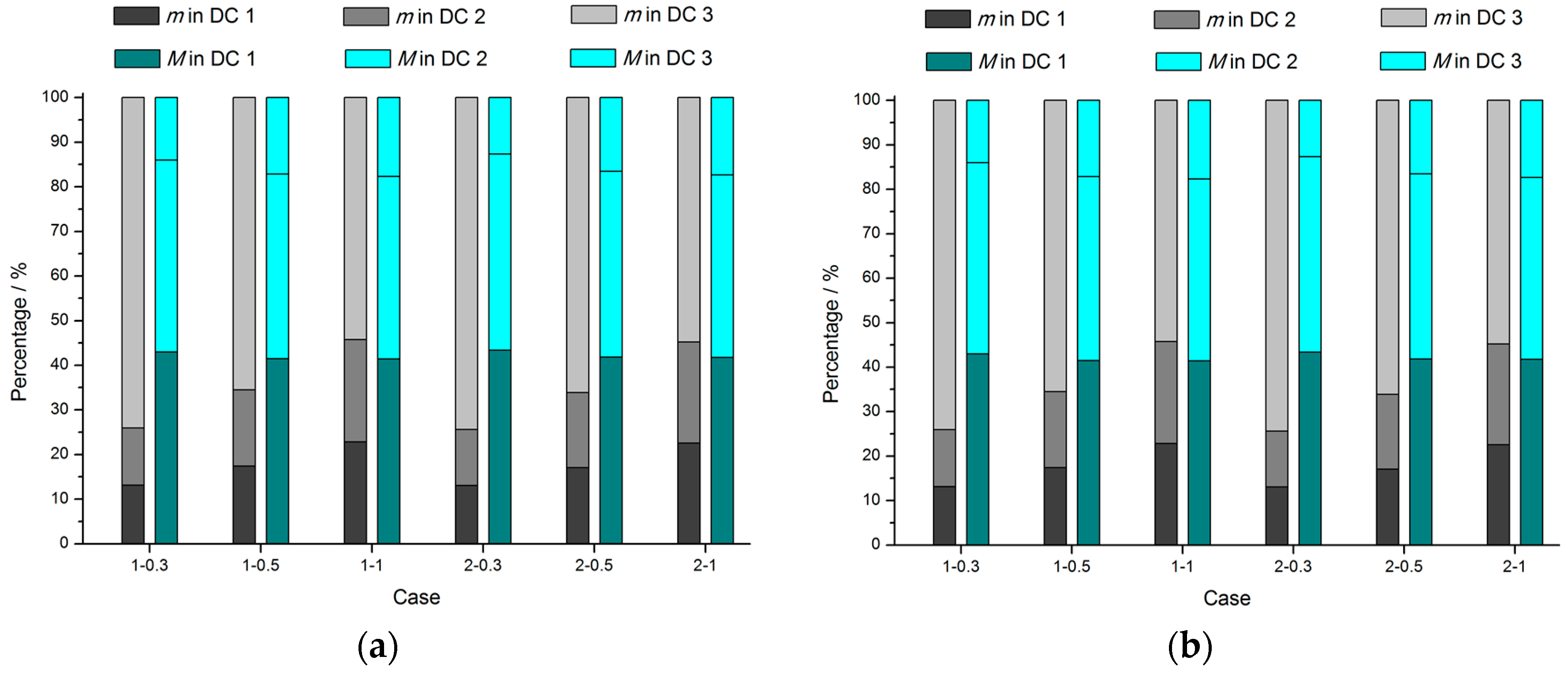
3.1.3. Percentages of Mass Flow Rate and Torque in Disc Channels

Figure 6 shows the mass flow rate and torque percentages in three DCs for all the turbine cases at 30,000 r/min. In Figure 6, both percentages in DCs 1 and 2 are nearly equal for both kinds of turbines, which indicates that the flow fields in DCs 1 and 2 are similar. In addition, DCs 1 and 2 have more air than DC3, while generating more torque.
For the one-to-one turbine, as disc thickness changes, both percentages in each disc channel are almost the same for turbine cases with same disc spacing distance, respectively. The torque percentage of DC3 for the turbine cases with 0.5 mm in disc spacing distance are almost the same, about 17%, while that for turbine with 0.3 mm in disc spacing distance decreases to 12%. All these flow phenomena are explained in the next sections.
For the one-to-many turbine, the variation relationship of mass flow rate percentage with disc spacing distance is not coincident. For the turbine cases with disc thickness of 1 mm, those in DCs 1 and 2 decrease as disc spacing distance increases, while for the turbine cases with disc thickness of 2 mm, they decrease first and then increase. In detail, those of Cases 1-1 and 2-1 reach the minimum values respectively. Moreover, disc thickness and spacing distance have few effects on the torque percentage in each disc channel.
To be noted, the calculation domain has five disc rotating walls and the average torque percentage is 20%. However, for all the turbine cases, the torque percentage in DC3 is less than 20%. Meanwhile, DC3 flows more working fluid than DCs 1 and 2. That means DC3 uses much more working fluid and generates less torque and power. Thus, the disc spacing distance of DC3 should be smaller to get less working fluid. To sum up, disc thickness slightly influences the aerodynamic performance of the one-to-one turbine. The isentropic efficiency of the turbine cases with disc thickness of 2 mm is a little lower than that of 1 mm. Specifically, for turbine cases with 0.5 mm in disc spacing distance, it decreases by only 7% at most rotational speeds. Moreover, the disc spacing distance affects greatly the aerodynamic performance of the one-to-one turbine, and an optimal disc spacing distance exists to make the turbine obtain the highest isentropic efficiency.
Both the disc thickness and spacing distance have significant impacts on the aerodynamic performance of the one-to-many turbine. The one-to-many turbine also has an optimal disc spacing distance, which is larger than that for the one-to-one turbine (1 mm and 0.5 mm, respectively, for turbine with disc thickness of 1 mm). In addition, the performance becomes remarkably worse with an increase in disc thickness (a reduction of about 45%).

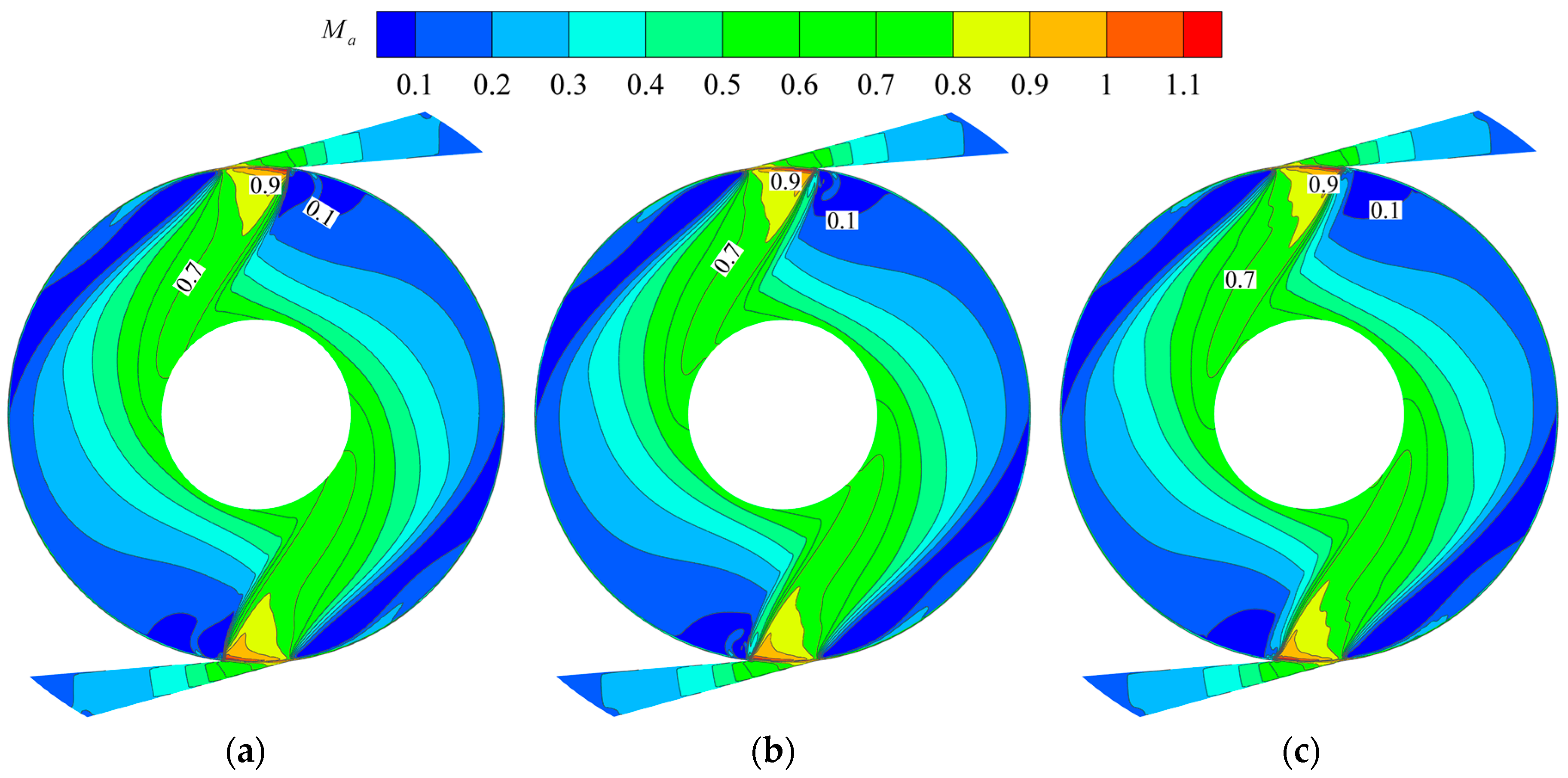
3.2. Flow Status of One-To-One Multichannel Tesla Turbines

From the above discussion, the isentropic efficiency of the one-to-one Tesla turbine drops a little as disc thickness increases. It increases first and then decreases with increasing disc spacing distance, and reaches its maximum value for the turbine case with disc spacing distance of 0.5 mm at lower rotational speeds including the optimal rotational speed of 30,000 r/min. To reveal the reasons that the disc thickness and spacing distance affect the turbine performance, the flow characteristics in the Tesla turbine were analyzed.

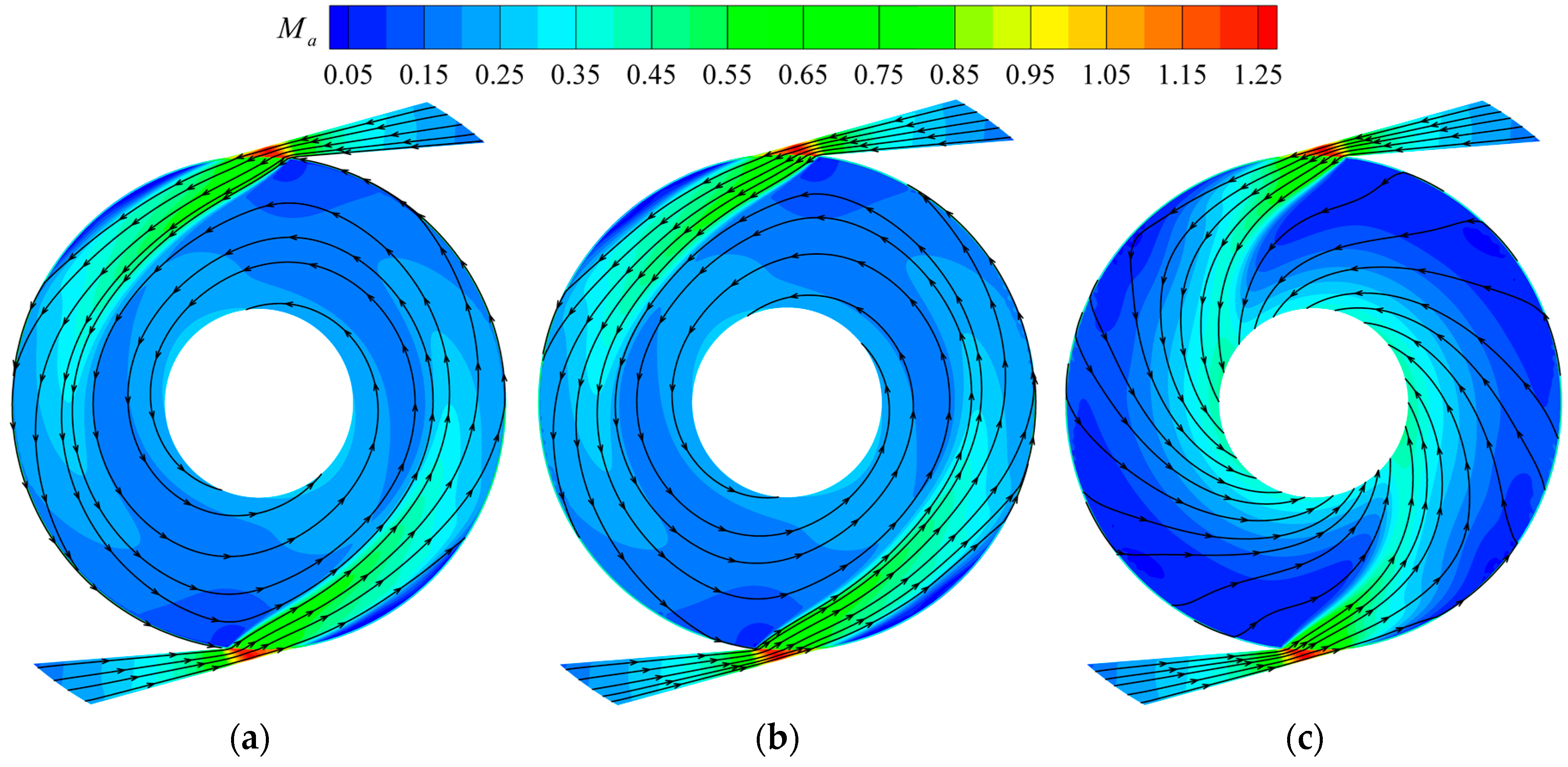
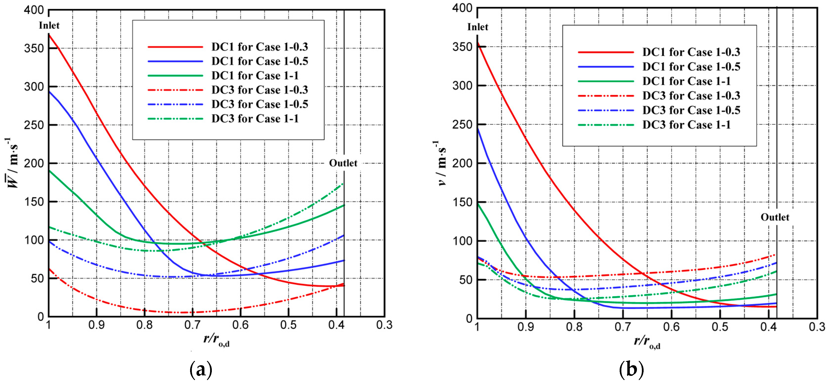
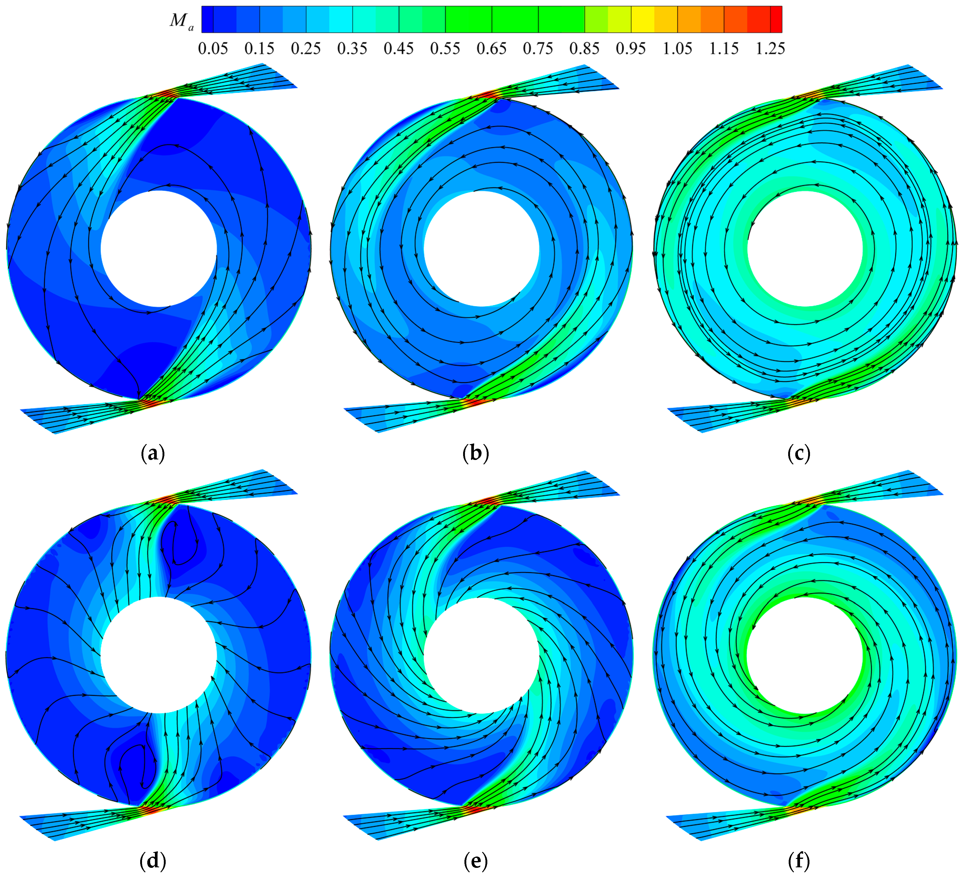
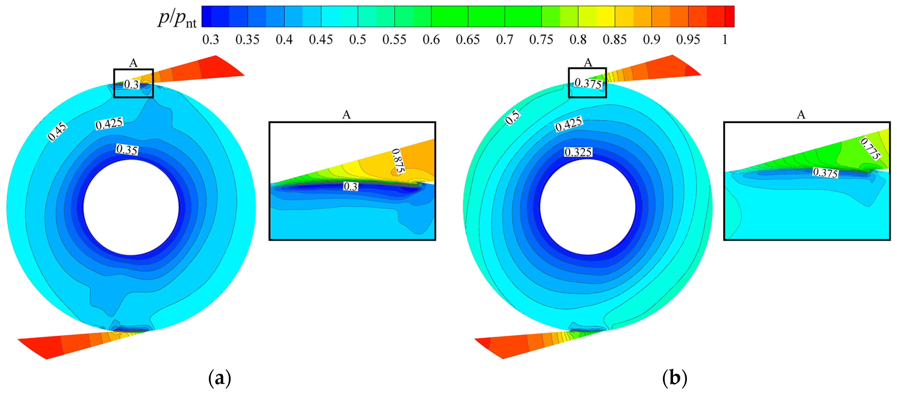
3.2.1. One-To-One Turbine with Different Disc Thickness

Figure 7 and Figure 8 show Mach number contours and streamlines and on the mid-sections of three DCs for the one-to-one turbine Cases 1-0.5 and 2-0.5 at 30,000 r/min, respectively. The streamlines and Mach number contours of DCs 1 and 2 are almost the same, but different from that of DC3, which agrees well with the above analysis. Therefore, in the next analysis, only the flow fields of DCs 1 and 3 are given.
Obviously, in flow channels 1 and 2, part of the air that just injects nearly tangentially into the disc channels flows into the N-R chamber due to centrifugal force, and finally flows into DC3. In flow channel 3, the air from the nozzle together with that from the N-R chamber flows into DC3 at a larger flow angle (relative to the tangential direction). Thus, it is easy to know that for the one-to-one turbine less air flows through DCs 1 and 2 than that through DC3. In addition, it can be observed that the Mach number on the mid-sections of DCs 1 and 2 is much higher than that of DC3, and the flow angle is much less than that in DC3, which leads to much higher relative tangential velocity and longer path lines in DCs 1 and 2. Therefore, the torque percentage in DC3 is lower than its average value of 20%.
Comparing Figure 7 and Figure 8, the flow fields in each disc channel of the turbine cases with same disc spacing distance but different disc thickness have little difference. This indicates that their aerodynamic performance also has little difference.
Figure 9 illustrates the contours of relative tangential velocity and vector distributions on the radial cross-section of 0°, whose location is marked in Figure 1. In this figure, only a small part of the disc channels is presented and the axial size is doubled to show the flow field clearly. The reference vector is given near the text of “rotor”.
In the disc channels, the contour represents the relative tangential velocity, and the vector indicates the radial and axial velocities. In the stator, the contour shows the velocity normal to this section, and the vector describes the axial velocity and another velocity on this section. In the disc channels, the positive relative tangential velocity indicates that the air at this region generates usable torque; otherwise, it consumes external mechanical energy, most of which appears near the casing wall.
Figure 9 indicates that on this section the axial velocity is close to zero, and the radial velocity is much lower than the relative tangential velocity. In addition, the air with high velocity flows from the nozzle through the N-R chamber and finally into the disc channels rapidly with little flow deflection to the axial direction. Some vortex generates at some region of the N-R chamber.
The flow fields for turbine Cases 1-0.5 and 2-0.5 are almost the same in most regions on the radial cross-section. However, the flow velocity of the working fluid in the N-R chamber for turbine Case 2-0.5 is much lower than that for Case 1-0.5, which consumes more extra energy to move them. Moreover, it can be observed from the relative tangential velocity contours that the tangential velocity gradient near the rotating disc walls for Case 2-0.5 is a little less than that for Case 1-0.5, which leads to lower torque. All these factors lead to the isentropic efficiency of Case 2-0.5 a little lower than that of 1-0.5 (23.92% and 23.04%, respectively).
To sum up, the flow field and aerodynamic performance of the one-to-one Tesla turbine changes a little with disc thickness. In detail, the isentropic efficiency of the turbine with the thicker disc is little lower, which results from lower velocity in the N-R chamber and a little lower tangential velocity gradient close to the disc walls.

3.2.2. One-To-One Turbine with Different Disc Spacing Distance

To reveal the detailed flow characteristics in the disc channels of the one-to-one turbine with different disc spacing distance, Figure 10 shows the variation curves of circumferential mass flow average velocity, including relative tangential velocity and radial velocity, versus the radius ratio (local radius to rotor inlet radius) for different one-to-one turbine cases. In this figure, the abscissa values of 1 and 0.384 represent the rotor inlet and outlet, respectively.
As shown in Figure 10a, for all turbine cases, the average relative tangential velocity in DC1 obtains the highest value at the rotor inlet, and decreases with radius ratio due to the contribution to the output power. For turbine Cases 1-0.5 and 1-1, it then increases as radius ratio continues to decrease (the air flows towards the turbine outlet), and the stationary point of velocity occurs much earlier with increasing disc spacing distance. In addition, the average relative tangential velocity decreases at the region near the rotor inlet and increases at the region near the rotor outlet with increasing disc spacing distance. Similarly, the average relative tangential velocity in DC3 for all turbine cases decreases first and then increases as the air flows towards the turbine outlet. However, it is much higher for the turbine cases with larger disc spacing distance. In general, the average relative tangential velocity difference between DCs 1 and 3 decreases with increasing disc spacing distance.
As shown in Figure 10b, for all turbine cases, the average radial velocity in DC1 decreases with radius ratio, which seems to violate the continuity equation of working fluid. The flow area (cylindrical surface of the disc channel) decreases as the air flows through the disc channels to the rotor outlet (radius ratio decreases), while the density also decreases, thus the radial velocity should increase based on the continuity equation. However, it is completely opposite to the results in Figure 10, which is due to the partial admission of the nozzled Tesla turbine. These discrete nozzles are installed symmetrically at the disc tip, and most air is injected into DCs 1 and 2 by the nozzles. Although the flow area decreases as radius ratio decreases, the effective flow area increases due to the air diffusion when the air flows from the rotor inlet to outlet, which leads to a decrease in average radial velocity in DC1.
In addition, the average radial velocity in DC3 decreases first and then increases; however, it has much less variation than that in DC1. Some air from the N-R chamber flows into DC3, and the effective flow area of DC3 is much larger than that of DC1. However, the flow velocity at the rotor inlet from the N-R chamber is much less, and the average radial velocity still decreases slightly due to air diffusion. As the air flows towards the rotor outlet, the average radial velocity has a slight increase due to the pressure drop the rotor and the decrease in effective flow area. Moreover, the average radial velocity in DCs 1 and 3 both decreases with increasing disc spacing distance, and the average radial velocity at the rotor inlet in DC1 is much higher than that in DC3.
In summary, the relative tangential velocity, determining the torque and power, decreases with radius ratio due to outputting power, and then increases slightly, resulting from the decrease in disc rotational linear velocity and the pressure in the drop. Furthermore, its difference between DCs 1 and 3 decreases with increasing disc spacing distance. Moreover, the radial velocity, depending on the mass flow rate, has a strong relationship with the effective flow area, and it decreases with increasing disc spacing distance.
Figure 11 shows Mach number contours and streamlines and on the mid-sections of DCs 1 and 3 for the one-to-one turbine cases with different disc spacing distance at 30,000 r/min.
As shown in Figure 11, the Mach number at the nozzle outlet decreases as disc spacing distance increases because of the higher pressure drop in the disc channels of the turbine cases with wider disc spacing. With increasing flow velocity at the nozzle outlet, the flow angle at the rotor inlet should decrease if the nozzle outlet flow angle of different turbine cases is the same. However, it is totally opposite to the flow fields in Figure 11, which is because the nozzle outlet flow angle changes with disc spacing distance despite their same nozzle outlet geometrical angles. The air in the scarfed part of the nozzle tends to speed up and changes its direction to the side without the nozzle wall, when the pressure ratio of the nozzle (nozzle outlet pressure to nozzle inlet pressure) is under the critical pressure ratio of air. The deflection angle goes up with an increase in difference value between the nozzle pressure ratio and the critical pressure ratio, as shown in turbine Cases 1-0.3 and 1-0.5 in Figure 11. When the nozzle pressure ratio is over the critical pressure ratio, the flow will not deflect in the scarfed part and the flow angle at the rotor inlet is almost equal to the nozzle outlet geometrical angle, shown in turbine Case 1-1.
Comparing the flow fields in DCs 1 and 3, it can be found that more air flows into DC3 from both the nozzle and the N-R chamber, and the velocity of the working fluid from the N-R chamber is much lower. Therefore, the average relative tangential velocity and radial velocity at the rotor inlet of DC3 are under those of DC1. Apart from DC1 for turbine Case 1-0.3, the flow velocity in other disc channels decreases first and then increases as the radius decreases. Moreover, the flow field difference between DCs 1 and 3 decreases with increasing disc spacing distance. All the above flow phenomena are the same as those in Figure 10.
Based on the above discussion, the isentropic efficiency of the one-to-one turbine goes up first and then down with increasing disc spacing distance, that is to say, an optimal disc spacing distance exists to allow a Tesla turbine to obtain the highest isentropic efficiency. To explain this phenomenon, Table 5 gives the coefficients of component energy loss for the one-to-one turbine cases at 30,000 r/min, including the nozzle loss, the disc loss and the leaving-velocity loss, which are defined as each component energy loss divided by the isentropic enthalpy drop across the whole turbine.
With increasing disc spacing distance, the nozzle loss coefficient goes down and the leaving velocity loss coefficient goes up remarkably. The disc loss coefficient increases first and then decreases, and its variation values are relatively lower than those of the nozzle loss and the leaving-velocity loss.
The variation rules of the component energy loss for the one-to-one turbine with disc spacing distance are analyzed in detail based on the flow fields. In the multichannel Tesla turbine, the nozzle energy loss includes the loss resulting from the viscous friction (called “friction loss in the nozzle”), and the loss occurring in the nozzle and the N-R chamber caused by the sudden variation of flow area, when the air flows through the nozzle and the N-R chamber and finally to the disc channels (called “local loss in the nozzle”). For the one-to-one turbine, the friction loss in the nozzle decreases with increasing disc spacing distance, caused by a decrease in proportion of the boundary layer in the nozzle channel and a decrease in flow velocity (Figure 11). In addition, most air flows out of the nozzle to the disc channels quickly (Figure 9), and the N-R chamber has little influence on the flow field. Thus, the local loss in the nozzle slightly influences the nozzle loss. In detail, the flow area ratio of the N-R chamber to the disc channels decreases with increasing disc spacing distance, therefore, the local loss for the one-to-one turbine decreases. As a result, the nozzle loss, including the friction loss and the local loss, decreases remarkably with increasing disc spacing distance.
With an increase in disc spacing distance, more air outside the boundary layer has no use in momentum exchange, which indicates more energy loss in the rotor. This is in agreement with the result in one channel Tesla turbines [28]. The local loss occurring in the disc channels due to the flow area variation has a decrease with increasing disc spacing distance, although the local loss also has little influence on the disc loss. Therefore, the combined actions of the two factors lead to increasing first and then decreasing disc loss as disc spacing distance increases. The Mach number at the turbine outlet rises with disc spacing distance, resulting in increasing leaving-velocity loss coefficient, as shown in Figure 11. These results are the same as those in Table 5.

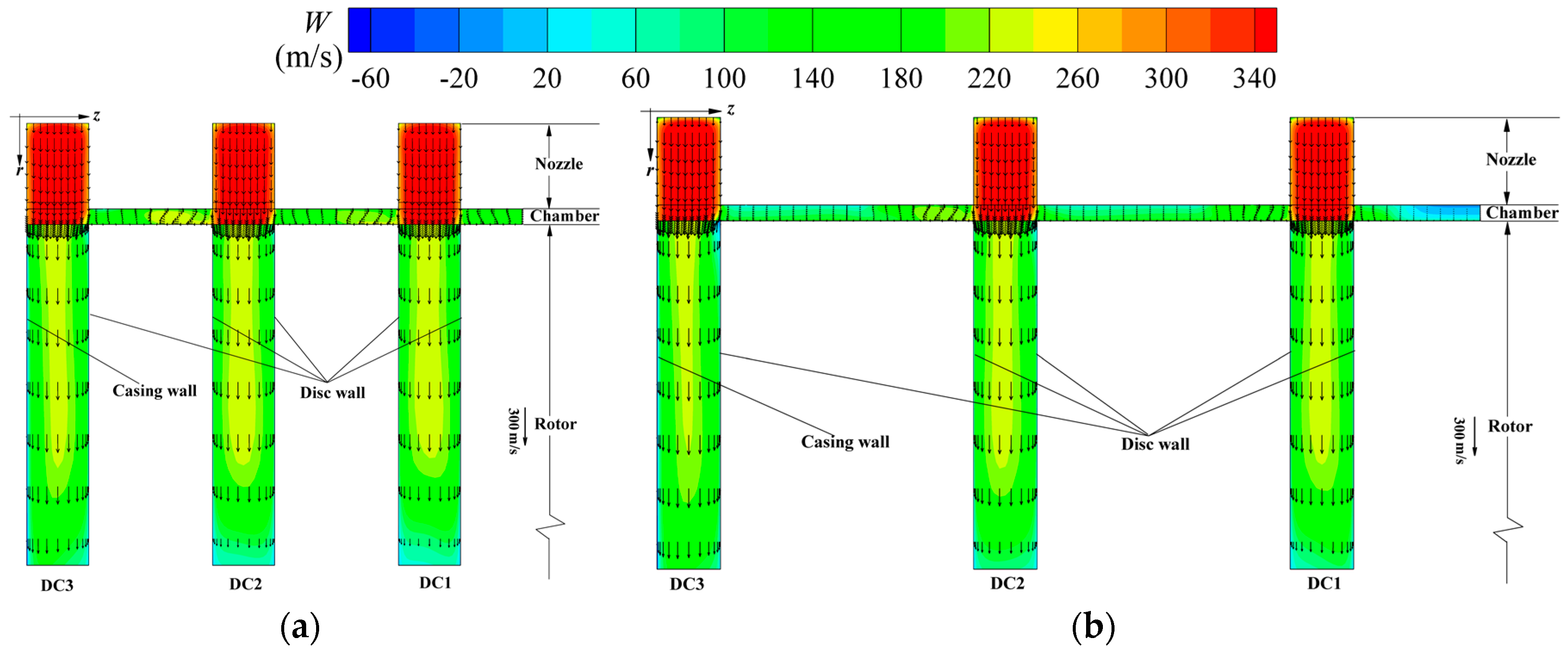
3.3. Flow Status of One-To-Many Multichannel Tesla Turbines

As discussed in the above section, the isentropic efficiency of the one-to-many turbine goes up first and then down with increasing disc spacing distance. It decreases remarkably as disc thickness increases. Table 6 gives the coefficients of component energy loss for the one-to-many turbine cases at 30,000 r/min. With increasing disc spacing distance, the nozzle loss coefficient and disc loss coefficient decrease, and the leaving-velocity loss coefficient rises. With increasing disc thickness, the nozzle loss has a slight increase, the disc loss decreases, and the leaving-velocity loss increases remarkably. The variation rules of these coefficients are explained in the following text.

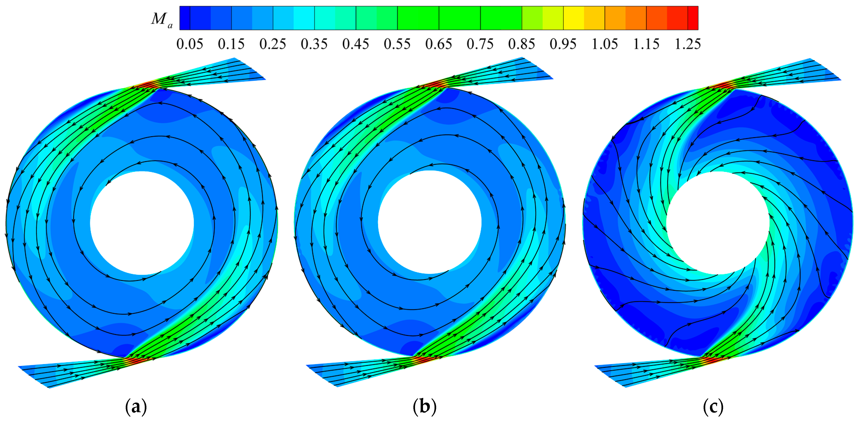
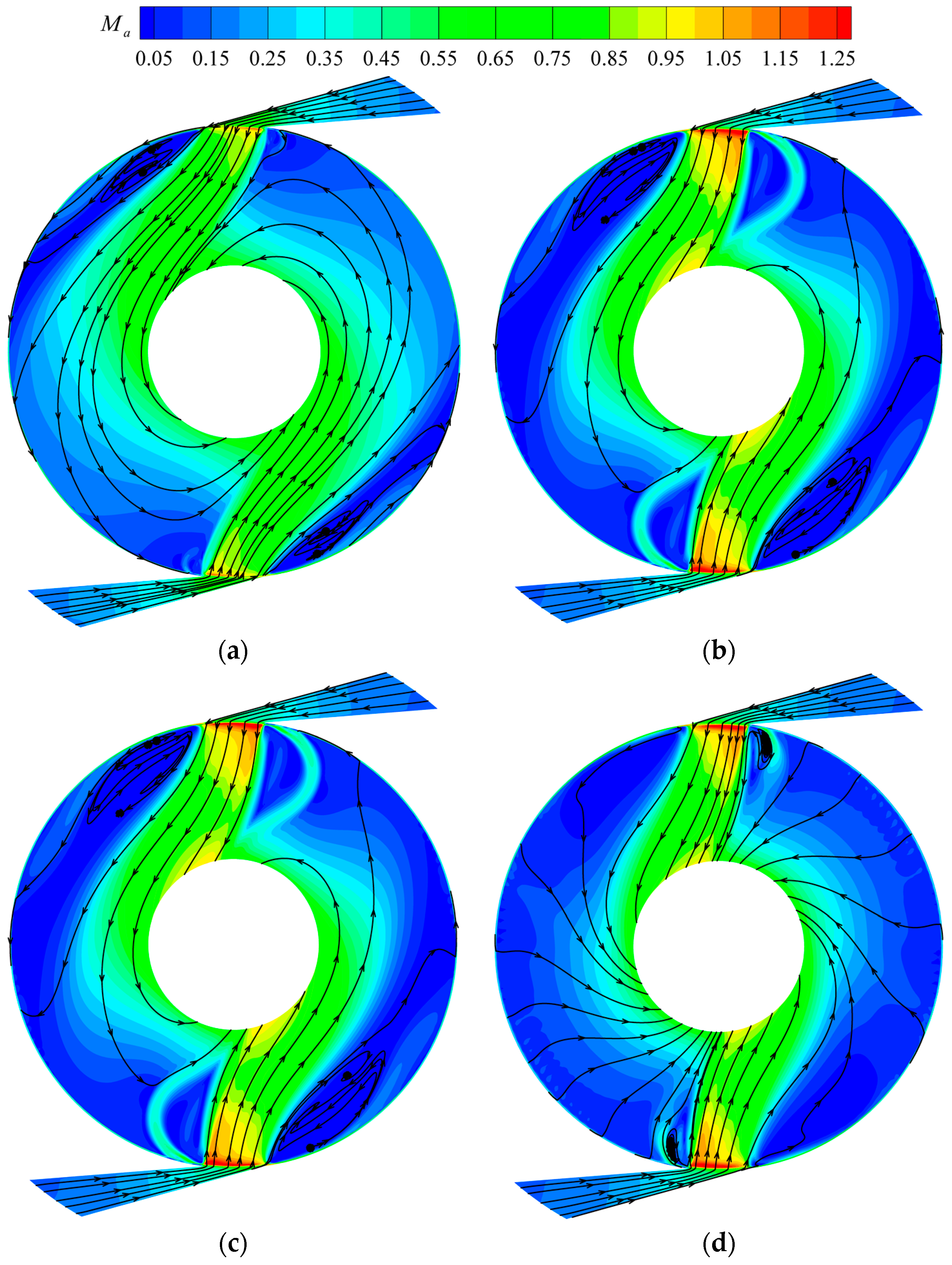
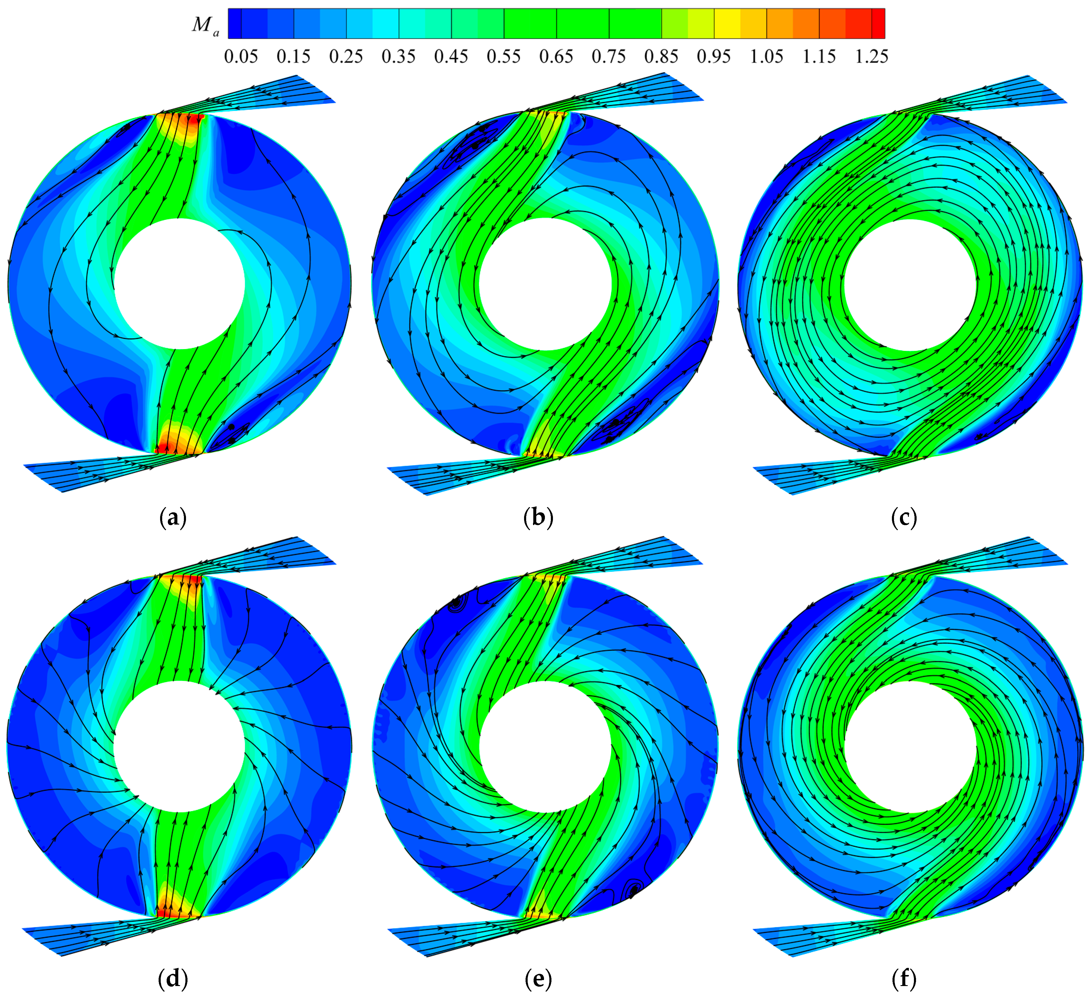
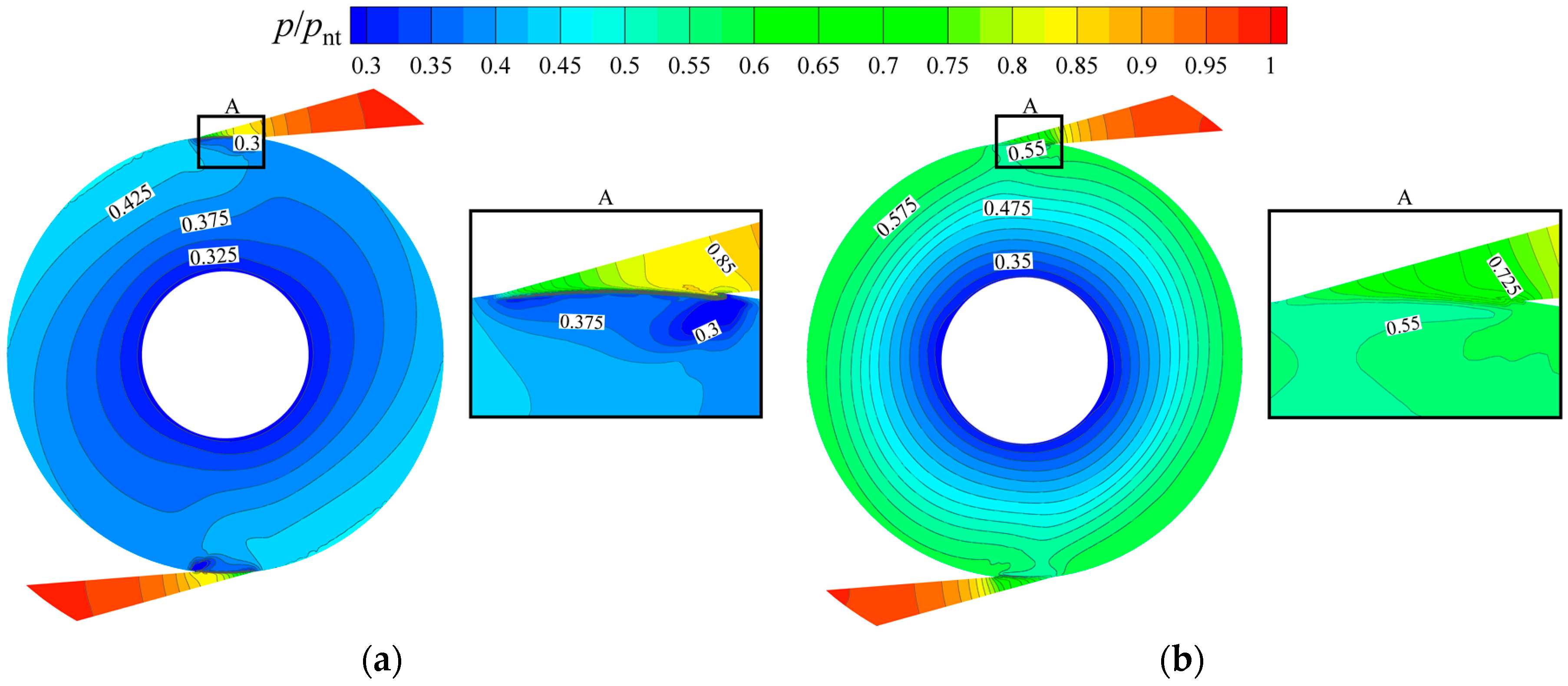
3.3.1. One-To-Many Turbine with Different Disc Thickness

To explain the variation rules of the aerodynamic performance of the one-to-many turbine with disc thickness, Figure 12 presents Mach number contours and streamlines on the mid-sections of DCs 1 and 3 for turbine Cases 1-0.5 and 2-0.5.
The Mach number at the nozzle outlet for Case 1-0.5 is slightly higher than that for Case 2-0.5. Therefore, the flow angle at the rotor inlet is a little lower. Moreover, the flow angle in most regions of the disc channels for Case 1-0.5 is lower than that for Case 2-0.5, leading to longer path lines and more momentum exchange. Different from the one-to-one turbine, Mach number increases suddenly at the rotor inlet directly facing the nozzle outlet, which is due to a sudden increase in flow area when the air passes the N-R chamber to the disc channels. The flow velocity at that place increases more significantly for Case 2-0.5 than that for Case 1-0.5.
Figure 13 presents the contours of the pressure ratio on the mid-sections of DC1 for the one-to-many turbine cases, and the pressure ratio equals the ratio of the local pressure to the turbine inlet total pressure. The pressure ratio at the nozzle outlet for Case 1-0.5 is lower than that for Case 2-0.5, due to lower flow area ratio of the nozzle channel to the disc channels. It indicates a higher pressure drop in the nozzle and higher flow velocity at the nozzle outlet for Case 1-0.5 (Figure 12 and Figure 13). A sudden decrease in pressure ratio also occurs at the same region of the sudden increase in Mach number. The pressure ratio decreases more remarkably for Case 2-0.5 than that for Case 1-0.5, because of much more decrease in flow area when the air flows through the N-R chamber to the disc channels.
The following is the detailed analysis of the component energy loss for the one-to-many turbine cases with different disc thickness based on the flow fields. With increasing disc thickness, the proportion of the boundary layer in the nozzle channel decreases and the flow velocity also decreases, which leads to lower friction loss in the nozzle. Actually, compared with the one-to-one turbine, the nozzle friction loss of the one-to-many turbine is much lower due to much less proportion of the boundary layer in the nozzle channel. It should be quite little and has a little influence on the nozzle loss. The local loss in the nozzle for the turbine case with thicker discs is much higher than that with thinner discs because the flow area reduces more when the air flows out of the N-R chamber to the disc channels They lead to a little increase in nozzle loss coefficient with increasing disc thickness (see Table 6).
As disc thickness increases, the working fluid becomes much more due to the larger nozzle throat area, and the flow velocity in the disc channels becomes much higher (see Figure 12). This leads to less boundary layer thickness, leading to less energy loss in the disc channels. The local loss at the inlet of the disc channels goes up with disc thickness, due to the higher flow area ratio of the N-R chamber to the disc channels. As a result, the disc loss decreases with increasing disc thickness (Table 6). The Mach number at the turbine outlet is much higher for Case 2-0.5 than that for Case 1-0.5 (Figure 12), which leads to higher leaving-velocity loss.
Figure 14 gives contours of relative tangential velocity and vector distributions on the radial cross-sections of 0° for the one-to-many Tesla turbine cases. Unlike the one-to-one turbine, the air at the nozzle outlet in the one-to-many turbine bends to the axial direction to flow into the disc channels, especially at the nozzle of which downstream is a wall. The vortex occurs on the downstream wall of the N-R chamber and the inlet of the disc channels, leading to the energy loss at those places. The energy loss on the downstream wall of the N-R chamber wall is the main source of the local loss in the nozzle. That at the inlet of the disc channels is a part of the disc loss, which also includes the friction loss.
Compared with turbine Case 1-0.5, the flow velocity at the nozzle outlet for turbine Case 2-0.5 is lower, thus leading to a larger flow angle at the rotor inlet. The radial velocity at the rotor inlet is higher and the relative tangential velocity is lower. In addition, the vortex on the downstream wall of the N-R chamber and at the inlet of the disc channels for turbine Case 2-0.5 is much larger than that for turbine Case 1-0.5, therefore the energy loss caused by the variation of the flow area for Case 2-0.5 is much higher.
Combining Figure 12 and Figure 14, the relationship of the mass flow rate percentages in each disc channel of the one-to-many turbine with disc thickness is analyzed. Compared with Case 1-0.5, the flow angle in DC1 for Case 2-0.5 is much larger, causing more air to flow through DC1 for Case 2-0.5. The mass flow rate of the air flowing into each disc channel of the one-to-many turbine has a significant difference from that of the one-to-one turbine. Figure 14 shows that the nozzle outlet area of the air flowing into DCs 1 and 2 is the same, and equals to the corresponding area of one disc spacing distance and one disc thickness. It is larger than that flowing into DC3, which equals to the corresponding area of one disc spacing distance and half of disc thickness. The area ratio of the working fluid flowing into DC1 to DC3 increases with disc thickness, leading to increasing mass flow rate percentage in DC1. Based on the two factors, the mass flow rate percentage in DC1 for Case 2-0.5 is higher than that for Case 1-0.5, which agrees with the results in Figure 6.

3.3.2. One-To-Many Turbine with Different Disc Spacing Distance

Mach number contours and streamlines on the mid-sections of DCs 1 and 3 for the one-to-many turbine cases with different disc spacing distance are presented in Figure 15. With increasing disc spacing distance, the Mach number increases at the nozzle outlet, which leads to lower flow angle at the rotor inlet. Thus, the turbine cases with larger disc spacing have longer path lines. Moreover, the sudden increase in Mach number at the rotor inlet decreases significantly with increasing disc spacing distance.
As discussed above, some air in DC1 passes through the N-R chamber and finally flows into DC3, which leads to more air in DC3 than that in DC1. For the turbine cases with disc thickness of 1 mm, with increasing disc spacing distance, the working fluid in DC1 flowing into the N-R chamber becomes much less due to less flow angle; with increasing disc spacing distance, the nozzle outlet area ratio of the air flowing into DC1 to that into DC3 decreases, causing less air in DC1. Under the combined actions of the two factors, the air in DC1 becomes less with increasing disc spacing distance.
With increasing disc spacing distance, the local loss in the N-R chamber decreases, resulting from a decrease in flow area ratio of the N-R chamber to the disc channels. Based on the above analysis, the friction loss in the nozzle of the one-to-many turbine is quite little and has few contributions to the nozzle loss. Thus, the nozzle loss decreases with increasing disc spacing distance (Table 6).
For the one-to-many turbine, the energy loss in the disc channels also increases with disc spacing distance, which is the same as the one-to-one turbine. In addition, the local loss occurring at the inlet of the disc channels decreases with increasing disc spacing distance significantly. Thus, the disc loss of the one-to-many turbine decreases significantly with increasing disc spacing distance. Moreover, the leaving-velocity loss goes up with disc spacing distance, resulting from increasing Mach number at the turbine outlet (Figure 15).
Figure 16 shows the contours of pressure ratio on the mid-sections of DC1 for the one-to-many turbine cases with different disc spacing distance. The pressure ratio variation with increasing disc spacing distance is same as that with decreasing disc thickness, which is because both decreasing disc thickness and increasing disc spacing distance lead to a decrease in flow area ratio of the nozzle channel to the disc channels for the one-to-many turbine. In general, an increase in flow area ratio of the nozzle to disc channels leads to an increase in pressure at the nozzle outlet and a significant decrease in pressure at the rotor inlet facing the nozzle outlet. Therefore, the flow velocity at the nozzle outlet decreases and that at the rotor inlet increases much more.

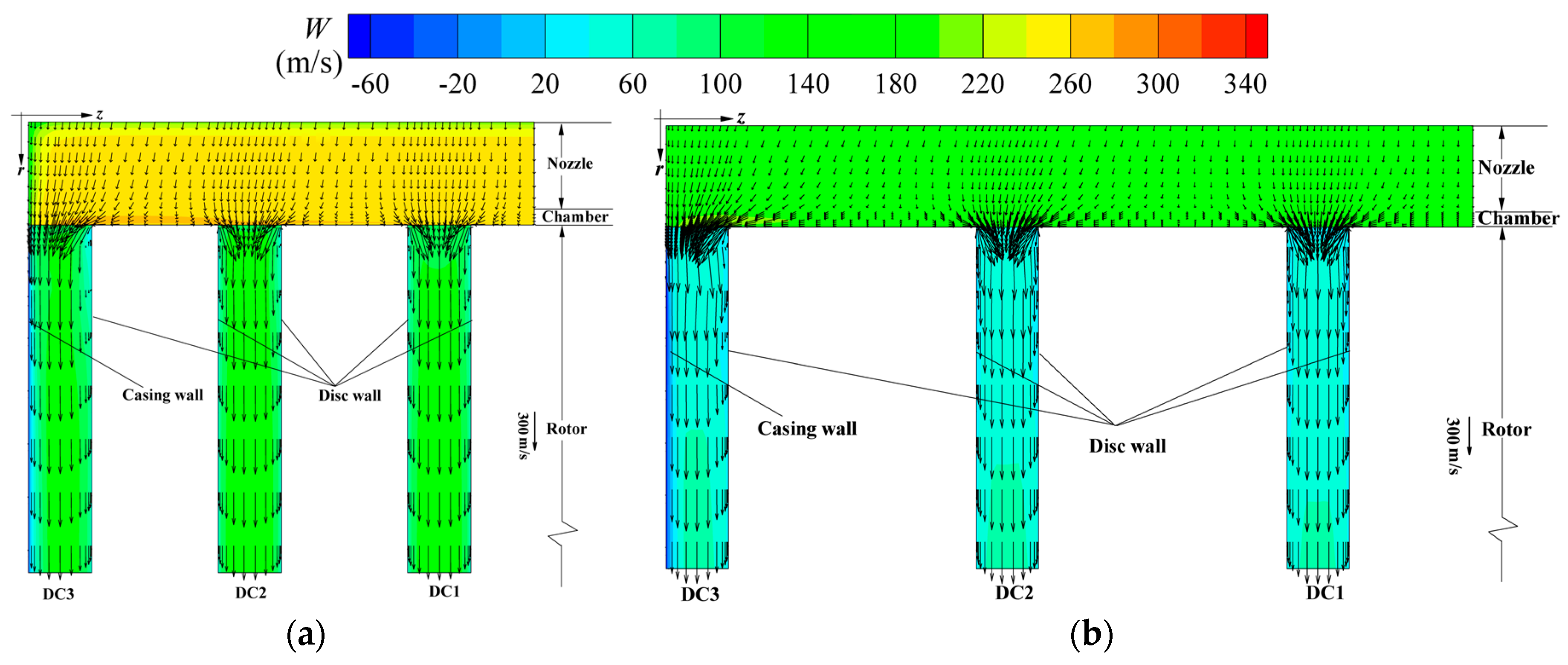
3.4. Influence of Disc Thickness and Spacing Distance on Energy Loss

As discussed above, the disc thickness has a little influence on the aerodynamic performance of the one-to-one Tesla turbine. In detail, the isentropic efficiency has a slight decrease with increasing disc thickness (less than 7% reduction for the turbine with 0.5 mm in disc spacing distance). That of the one-to-many turbine decreases significantly with disc thickness (decrease of about 45% for the turbine with 0.5 mm in disc spacing distance), which is due to higher leaving-velocity. For both the one-to-one turbine and the one-to-many turbine, the isentropic efficiency goes up first and then down with increasing disc spacing distance.
For the one-to-one turbine, the flow coefficient remains unchanged with the variation of disc thickness, and it increases with disc thickness for the one-to-many turbine. In addition, it increases with decreasing disc spacing distance for both two kinds of turbines. This coefficient of the one-to-one turbine is much lower than that of the one-to-many turbine with same disc spacing distance and disc thickness (The former is about half of the latter for turbine Case 1-0.5).
The nozzle loss of the multichannel Tesla turbine includes the friction loss and the local loss. That of the one-to-one turbine decreases with increasing disc spacing distance; that of the one-to-many turbine decreases with increasing disc spacing distance and increases slightly with increasing disc thickness. In general, the one-to-one turbine has higher nozzle loss than the one-to-many turbine (18.49% and 5.78%, respectively, for Case 1-0.5) due to much higher friction loss of the one-to-one turbine, although the local loss of the one-to-one is lower than that of the one-to-many turbine. Combining the discussion in the previous sections, it can be concluded that most of the nozzle loss is the friction loss for the one-to-one turbine, while, for the one-to-many turbine, the local loss in the nozzle is competitive with the friction loss in the nozzle. The friction loss decreases rapidly with a decrease in proportion ratio of the boundary layer in the nozzle channel. In detail, it drops with increasing disc spacing distance for the one-to-one turbine and increasing disc spacing distance or disc thickness for the one-to-many turbine, and the friction loss of the one-to-many turbine is quite low. The local loss in the nozzle decreases with decreasing flow area ratio of the N-R chamber to the disc channels, which is increasing disc spacing distance or decreasing disc thickness.
For the one-to-one turbine, the disc loss goes up first and then down with increasing disc spacing distance, and its variation range is much less (about 2%), while, for the one-to-many turbine, it decreases significantly with increasing disc spacing distance and decreases a little with increasing disc thickness (the maximum variation is 24.56%). For both the one-to-one turbine and the one-to-many turbine, the disc energy loss in the disc channels rises with disc spacing distance. In addition, the local loss at the inlet of the disc channels decreases with increasing disc spacing distance. According to the variation rule of the local loss with disc spacing distance, it can be concluded that the local loss of the one-to-one turbine is less than that of the one-to-many turbine.
The leaving-velocity loss of the one-to-one turbine rises with disc spacing distance, while that of the one-to-many turbine goes up with both disc thickness and spacing distance. Moreover, compared with the one-to-one turbine, the leaving-velocity loss of the one-to-many turbine with same disc thickness and spacing distance is much higher (33.1% and 13.03%, respectively, for Case 1-0.5).

4. Conclusions

As one of the best alternative options for small-scale conventional bladed turbines, Tesla turbines can be comparable with conventional turbines when they are well designed. Two kinds of multichannel Tesla turbines (one-to-one Tesla turbine and one-to-many Tesla turbine) with different disc spacing distance and disc thickness were studied numerically to analyze the influence of the two rotor geometrical parameters on their aerodynamic performance and flow characteristics, which offers a theoretical guidance in the design method. The main conclusions are summarized as follows.
(1) For both the one-to-one turbine and the one-to-many turbine, the isentropic efficiency goes up first and then down with increasing disc spacing distance, thus an optimal disc spacing distance exists to allow the multichannel Tesla turbine to obtain the highest efficiency. With increasing disc thickness, the isentropic efficiency of the one-to-many turbine decreases dramatically, while that of the one-to-one turbine decreases slightly. For turbine cases with disc spacing distance of 0.5 mm, as disc thickness increases from 1 mm to 2 mm, the isentropic efficiency of the one-to-one turbine was lowered by less than 7% (relative variation), while that of the one-to-many turbine drops by about 45% (relative variation). In addition, the isentropic efficiency of the one-to-one turbine is more sensitive to rotational speed than the one-to-many turbine.
(2) For the one-to-one turbine, with increasing disc thickness, the flow field is similar for turbine cases with same disc spacing distance; the flow velocity in the N-R chamber and the relative tangential velocity gradient close to the disc walls decrease slightly, causing the isentropic efficiency to decrease slightly. With increasing disc spacing distance, the flow velocity at the nozzle outlet decreases, and the flow angle at the rotor inlet increases, leading to an increase in mass flow rate percentage of DCs 1 and 2.
(3) For the one-to-many turbine, with increasing disc thickness, the flow velocity at the nozzle outlet decreases and its sudden increase at the rotor inlet facing the nozzle outlet is greater; the flow angle in the disc channels increases slightly and the flow velocity at the turbine outlet also increases. With increasing disc spacing distance, the flow velocity at the nozzle outlet goes up and its sudden increase becomes less; the flow angle in the disc channels decreases and the velocity at the rotor outlet increases.

Author Contributions

Conceptualization, W.Q. and Q.D.; Methodology, W.Q. and Q.D.; Investigation, W.Q. and Y.J.; Data Curation, W.Q. and Y.J.; Writing—Original Draft Preparation, W.Q.; Writing—Review and Editing, Q.D., Q.Y. and Z.F.; Visualization, W.Q. and Y.J.; and Supervision, Q.Y. and Z.F.

Funding

This research was supported financially by National Natural Science Foundation of China (grant number 51376143).

Conflicts of Interest

The authors declare no conflict of interest.

Nomenclature

bdisc spacing distance, mm
cradial clearance of nozzle-rotor chamber, mm
cpspecific heat at constant pressure, J/kg·K
Cmflow coefficient
ddiameter, mm
hstatic enthalpy, m2/s2
htotmean total enthalpy, m2/s2
kturbulent kinetic energy,
mmass flow rate, kg/s
Mtorque, N·m
MaMach number
nrotational speed of the rotor, r/min
Nnumber
pabsabsolute pressure
pnt/piratio of total pressure at the nozzle inlet to pressure at the turbine outlet
Ppower, kW
Pr t turbulent Prandtl number
rradial coordinate or radius, mm
Rspecific gas constant of air,
SEenergy source, kg/(m·s3)
SMmomentum source, kg/(m2·s2)
ttime, s
thdisc thickness, mm
Ttemperature, K
Tnttotal temperature at the nozzle inlet, K
Ujaveraged velocity in three directions, m/s
vaverage radial velocity, m/s
Wrelative tangential velocity, m/s
W ¯ average relative tangential velocity, m/s
xjcoordinates in three directions, m
zaxial coordinate, m
α nozzle exit geometrical angle (relative to the tangential direction), °
γ specific heat ratio
Γ t eddy diffusivity, kg/(m·s)
δ relative variation of parameters
Δ h isen isentropic enthalpy drop of the whole turbine, J/kg
η isentropic efficiency
θ circumferential coordinate, rad
μ t eddy viscosity or turbulent viscosity, kg/(m·s)
ρ density, kg/m3
ρ u i u j ¯ Reynolds stresses
ρ u j h ¯ turbulence flux
ρ u i ϕ ¯ Reynolds flux
τ molecular stress tensor, kg/(m·s2)
ω turbulent frequency, s-1
Ω rotational angular speed, rad/s
Subscripts
ddisc
dcdisc channel
iinner
nnozzle
oouter

References

  1. Gerendas, M.; Pfister, R. Development of a very small aero-engine. In Proceedings of the ASME Turbo Expo 2000, Munich, Germany, 8–11 May 2000. [Google Scholar]
  2. Capata, R.; Sciubba, E. Experimental fitting of the re-scaled Balje maps for low-Reynolds radial turbomachinary. Energies 2015, 8, 7686–8000. [Google Scholar] [CrossRef]
  3. Capata, R.; Saracchini, M. Experimental campaign tests on ultra micro gas turbines, fuel supply comparison and optimization. Energies 2018, 11, 799. [Google Scholar] [CrossRef]
  4. Epstein, A.H. Millimeter-scale, MEMS gas turbine engines. J. Eng. Gas Turbines Power 2015, 126, 205–226. [Google Scholar] [CrossRef]
  5. Fu, L.; Feng, Z.P.; Li, G.J. Experimental investigation on overall performance of a millimeter-scale radial turbine for micro gas turbine. Energy 2017, 134, 1–9. [Google Scholar] [CrossRef]
  6. Fu, L.; Feng, Z.P.; Li, G.J. Investigation on design flow of a millimeter-scale radial turbine for micro gas turbine. Microsyst. Technol. 2018, 24, 2333–2347. [Google Scholar] [CrossRef]
  7. Shan, X.C.; Zhang, Q.D.; Sun, Y.F.; Wang, Z.F. Design, fabrication and characterization of an air-driven micro turbine device. J. Phys. 2006, 34, 316–321. [Google Scholar] [CrossRef]
  8. Isomura, K.; Murayama, M.; Teramoto, S.; Hikichi, K.; Endo, Y.; Togo, S.; Tanaka, S. Experiment verification of the feasibility of a 100 W class micro-scale gas turbine at an impeller diameter of 10 mm. J. Micromech. Microeng. 2006, 16, s254–s261. [Google Scholar] [CrossRef]
  9. Kim, M.J.; Kim, J.H.; Kim, T.S. The effects of internal leakage on the performance of a micro gas turbine. Appl. Energy 2018, 212, 175–184. [Google Scholar] [CrossRef]
  10. Deam, R.T.; Lemma, E.; Mace, B.; Collins, R. On scaling down turbines to millimeter size. J. Eng. Gas Turbines Power 2008, 130, 052301. [Google Scholar] [CrossRef]
  11. Lampart, P.; Kosowski, K.; Piwowarski, M.; Jedrzejewski, L. Design analysis of Tesla micro-turbine operating on a low-boiling medium. Pol. Marit. Res. 2009, 16, 28–33. [Google Scholar] [CrossRef]
  12. Tesla, N. Turbine. U.S. Patent 1,061,206, 6 May 1913. [Google Scholar]
  13. Beans, E.W. Investigation into the performance characteristics of a friction turbine. J. Spacecr. 1966, 3, 131–134. [Google Scholar] [CrossRef]
  14. Breiter, M.C.; Pohlhausen, K. Laminar Flow between Two Parallel Rotating Disks. Available online: https://apps.dtic.mil/dtic/tr/fulltext/u2/275562.pdf (accessed on 8 April 2016).
  15. Rice, W. An analytical and experimental investigation of multiple-disk turbines. J. Eng. Power 1965, 87, 29–36. [Google Scholar] [CrossRef]
  16. Adams, R.; Rice, W. Experimental investigation of the flow between corotating disks. J. Appl. Mech. 1970, 37, 844–849. [Google Scholar] [CrossRef]
  17. Lemma, E.; Deam, R.T.; Toncich, D.; Collins, R. Characterisation of a small viscous flow turbine. Exp. Therm. Fluid Sci. 2008, 33, 96–105. [Google Scholar] [CrossRef]
  18. Carey, V.P. Assessment of Tesla turbine performance for small scale Rankine combined heat and power systems. J. Eng. Gas Turbines Power 2010, 132, 122301. [Google Scholar] [CrossRef]
  19. Sengupta, S.; Guha, A. A theory of Tesla disc turbines. Proc. Inst. Mech. Eng. Part A J. Power Energy 2012, 226, 650–663. [Google Scholar] [CrossRef]
  20. Guha, A.; Sengupta, S. The fluid dynamics of the rotating flow in a Tesla disc turbine. Eur. J. Mech. B/Fluid 2013, 37, 112–123. [Google Scholar] [CrossRef]
  21. Sengupta, S.; Guha, A. Analytical and computational solutions for three-dimensional flow-field and relative pathlines for the rotating flow in a Tesla disc turbine. Comput. Fluids 2013, 88, 344–353. [Google Scholar] [CrossRef]
  22. Talluri, L.; Fiaschi, D.; Neri, G.; Ciappi, L. Design and optimization of a Tesla turbine for ORC applications. Appl. Energy 2018, 226, 300–319. [Google Scholar] [CrossRef]
  23. Hoya, G.P.; Guha, A. The design of a test rig and study of the performance and efficiency of a Tesla disc turbine. Proc. Inst. Mech. Eng. Part A J. Power Energy 2009, 223, 451–465. [Google Scholar] [CrossRef]
  24. Guha, A.; Smiley, B. Experiment and analysis for an improved design of the inlet and nozzle in Tesla disc turbines. Proc. Inst. Mech. Eng. Part A J. Power Energy 2010, 224, 261–277. [Google Scholar] [CrossRef]
  25. Schosser, C.; Lecheler, S.; Pfitzner, M. A test rig for the investigation of the performance and flow field of Tesla friction turbines. In Proceedings of the ASME Turbo Expo 2014, Düsseldorf, Germany, 16–20 June 2014. [Google Scholar]
  26. Lampart, P.; Jedrzejewski, L. Investigations of aerodynamics of Tesla bladeless microturbines. J. Theor. Appl. Mech. 2011, 49, 477–499. [Google Scholar]
  27. Deng, Q.H.; Qi, W.J.; Feng, Z.P. Improvement of a theoretical analysis method for Tesla turbines. In Proceedings of the ASME Turbo Expo 2013, San Antonio, TX, USA, 3–7 June 2013. [Google Scholar]
  28. Qi, W.J.; Deng, Q.H.; Feng, Z.P.; Yuan, Q. Influence of disc spacing distance on the aerodynamic performance and flow field of Tesla turbines. In Proceedings of the ASME Turbo Expo 2016, Seoul, Korea, 13–17 June 2016. [Google Scholar]
  29. Qi, W.J.; Deng, Q.H.; Jiang, Y.; Feng, Z.P.; Yuan, Q. Aerodynamic performance and flow characteristics analysis of Tesla turbines with different nozzle and outlet geometries. Proc. Inst. Mech. Eng. Part A J. Power Energy 2018, accepted. [Google Scholar] [CrossRef]
  30. Hidema, T.; Okamoto, K.; Teramoto, S.; Nagashima, T. Numerical investigation of inlet effects on Tesla turbine performance. In Proceedings of the AJCPP, Miyazaki, Japan, 4–6 March 2010. [Google Scholar]
  31. Sengupta, S.; Guha, A. Inflow-rotor interaction in Tesla disc turbines: Effects of discrete inflows, finite disc thickness, and radial clearance on the fluid dynamics and performance of the turbine. Proc. Inst. Mech. Eng. Part A J. Power Energy 2018. accepted. [Google Scholar] [CrossRef]
  32. Okamoto, K.; Goto, K.; Teramoto, S.; Yamaguchi, K. Experimental investigation of inflow condition effects on Tesla turbine performance. In Proceedings of the ISABE Conference 2017, Manchester, UK, 3–8 September 2017. [Google Scholar]
  33. Carlson, D.R.; Widnall, S.E.; Peeters, M.F. A flow-visualization study of transition in plane Poiseuille flow. J. Fluid Mech. 1982, 121, 487–505. [Google Scholar] [CrossRef]
  34. ANSYS. CFX-Solver Theory Guide; Release 12.1; ANSYS Inc.: Canonsburg, PA, USA, 2009. [Google Scholar]
Figure 1. Tesla turbine schematic: (a) 2-D sketch; and (b) 3-D rotor.
Energies 12 00044 g001
Figure 2. Sketch maps of multichannel Tesla turbines: (a) one-to-one Tesla turbine; and (b) one-to-many Tesla turbine.
Energies 12 00044 g002
Figure 3. Mach number contours on the mid-sections of DC1 for the one-to-many turbine Case 1-0.5 with three different node cases: (a) Case 1; (b) Case 2; and (c) Case 3.
Energies 12 00044 g003
Figure 4. Isentropic efficiency versus rotational speed of each turbine case for two kinds of multichannel Tesla turbines: (a) one-to-one Tesla turbine; and (b) one-to-many Tesla turbine.
Energies 12 00044 g004
Figure 5. Flow coefficient versus rotational speed of each case for two kinds of multichannel Tesla turbines: (a) one-to-one Tesla turbine; and (b) one-to-many Tesla turbine.
Energies 12 00044 g005
Figure 6. Mass flow rate and torque percentages in three DCs for two kinds of Tesla turbines at 30,000 r/min: (a) one-to-one Tesla turbine; and (b) one-to-many Tesla turbine.
Energies 12 00044 g006
Figure 7. Mach number contours and streamlines on the mid-sections of three DCs for the one-to-one turbine Case 1-0.5 at 30,000 r/min: (a) DC1; (b) DC2; and (c) DC3.
Energies 12 00044 g007
Figure 8. Mach number contours and streamlines on the mid-sections of three DCs for the one-to-one turbine Case 2-0.5 at 30,000 r/min: (a) DC1; (b) DC2; and (c) DC3.
Energies 12 00044 g008
Figure 9. Contours of relative tangential velocity and vector distributions on radial cross-sections of 0° for the one-to-one Tesla turbine cases at 30,000 r/min: (a) Case 1-0.5; and (b) Case 2-0.5.
Energies 12 00044 g009
Figure 10. Variation curves of circumferential mass flow average velocity versus the radius ratio for three one-to-one turbine cases: (a) relative tangential velocity; and (b) radial velocity.
Energies 12 00044 g010
Figure 11. Mach number contours and streamlines on the mid-sections of DCs 1 and 3 for the one-to-one turbine cases with different disc spacing distance at 30,000 r/min: (a) DC1 for Case 1-0.3; (b) DC1 for Case 1-0.5; (c) DC1 for Case 1-1; (d) DC3 for Case 1-0.3; (e) DC3 for Case 1-0.5; and (f) DC3 for Case 1-1.
Energies 12 00044 g011
Figure 12. Mach number contours and streamlines on the mid-sections of DCs 1 and 3 for the one-to-many turbine cases with different disc thickness at 30,000 r/min: (a) DC1 for Case 1-0.5; (b) DC1 for Case 2-0.5; (c) DC3 for Case 1-0.5; and (d) DC3 for Case 2-0.5.
Energies 12 00044 g012
Figure 13. Contours of pressure ratio on the mid-sections of DC1 for the one-to-many Tesla turbine cases with different disc thickness at 30,000 r/min: (a) Case 1-0.5; and (b) Case 2-0.5.
Energies 12 00044 g013
Figure 14. Contours of relative tangential velocity and vector distributions on radial cross-sections of 0° for the one-to-many Tesla turbine cases with different disc thickness: (a) Case 1-0.5; and (b) Case 2-0.5.
Energies 12 00044 g014
Figure 15. Mach number contours and streamlines on the mid-sections of DCs 1 and 3 for the one-to-many turbine cases with different disc spacing distance at 30,000 r/min: (a) DC1 for Case 1-0.3; (b) DC1 for Case 1-0.5; (c) DC1 for Case 1-1; (d) DC3 for Case 1-0.3; (e) DC3 for Case 1-0.5; and (f) DC3 for Case 1-1.
Energies 12 00044 g015
Figure 16. Contours of pressure ratio on the mid-sections of DC1 for one-to-many Tesla turbine cases with different disc spacing distance at 30,000 r/min: (a) Case 1-0.3; and (b) Case 1-1.
Energies 12 00044 g016
Table 1. Geometrical parameters of each case.
Group 1 (One-To-One Multichannel Tesla Turbines)
Caseth(mm)b(mm)b/th(-)
Case 1-0.310.30.3
Case 1-0.510.50.5
Case 1-1111
Case 2-0.320.30.15
Case 2-0.520.50.25
Case 2-1210.5
Group 2 (One-To-Many Multichannel Tesla Turbines)
Caseth(mm)b(mm)b/th(-)
Case 1-0.310.30.3
Case 1-0.510.50.5
Case 1-1111
Case 2-0.520.50.25
Case 2-1210.5
Case 2-2221
Table 2. Geometrical and aerodynamic parameters.
SymbolUnitValue
Nn(-)2
do,d(mm)100
di,d(mm)38.4
c(mm)0.25
Nd(-)5
Ndc(-)6
α (°)10
p nt / p i (-)3.42
Tnt(K)373
Table 3. Mesh information.
Case No.Stator (Nozzle/N-R Chamber)Rotor (Each Disc Channel)
Number of Nodes
( r , θ , z   Directions )
Total Node NumberNumber of Nodes
( r , θ , z   Directions )
Total Node Number
Case 1(55/13) × (36/269) × 99526,51665 × 288 × 23400,660
Case 2(67/17) × (45/335) × 107923,51781 × 333 × 29782,217
Case 3(87/21) × (57/417) × 1351,830,306102 × 417 × 371,581,306
Table 4. Mesh independence.
Case No.Node Number
(million)
m
(kg/s)
δ m ( % ) P (kW) δ P   ( % ) η (-) δ η   ( % )
Case 11.720.035760.6190.59601.5680.15040.940
Case 23.270.035620.2250.58860.3070.14910.067
Case 36.570.0355400.586800.14900
Table 5. Coefficients of component energy loss for one-to-one Tesla turbine cases.
Case NameNozzle Loss CoefficientDisc Loss CoefficientLeaving-Velocity Loss CoefficientIsentropic Efficiency
Case 1-0.30.28570.41960.07600.2187
Case 1-0.50.18490.44050.13030.2443
Case 1-10.10850.43580.24400.2117
Table 6. Coefficients of component energy loss for one-to-many Tesla turbine cases.
Case NameNozzle Loss CoefficientDisc Loss CoefficientLeaving-Velocity Loss CoefficientIsentropic Efficiency
Case 1-0.30.07240.55390.23870.1350
Case 1-0.50.05780.45740.33100.1538
Case 1-10.04170.39360.40550.1592
Case 2-0.50.06990.43240.40400.0937
Case 2-10.04710.35040.49250.1100
Case 2-20.03750.30830.55610.0981

