Article

Dual-Vector Predictive Torque Control of Permanent Magnet Synchronous Motors Based on a Candidate Vector Table

1
School of Electrical and Information Engineering, Tianjin University, Tianjin 300072, China
2
College of Electrical Engineering, Zhejiang University, Hangzhou 310027, China
3
Tianjin Engineering Center of Electric Machine System Design and Control, Tianjin Polytechnic University, Tianjin 300387, China
*
Author to whom correspondence should be addressed.
Energies 2019, 12(1), 163; https://doi.org/10.3390/en12010163
Submission received: 16 November 2018 / Revised: 22 December 2018 / Accepted: 28 December 2018 / Published: 4 January 2019

Abstract

:
In order to reduce the torque ripple of permanent magnet synchronous motors (PMSMs), this paper proposes a dual-vector predictive torque control strategy based on a candidate vector table. The main feature of this strategy is that two vectors are acted in a control period to form a vector combination, and the vector combination can be either an effective-zero combination or an effective-effective combination. In the process of establishing the vector combinations, the switching frequency is also taken into account, therefore avoiding a high switching frequency, while effectively reducing the motor torque ripple. The candidate vector table is constructed offline, and three sets of candidate vectors and their duty cycles can be determined by looking up the table. Then the cost function is used to screen the action vectors from the three sets candidate vectors, so the two vectors acted in one control period and their duty cycles can be obtained simultaneously. Finally, the feasibility and effectiveness of the proposed method are verified on a 5.2 kW two-level inverter-fed PMSM drive system.

1. Introduction

Permanent magnet synchronous motors (PMSMs) have the advantages of simple structure, reliable operation, high power density, and have been widely used in many industrial fields, such as aerospace, mechanical manufacturing, rail traffic and other industrial fields [1,2,3]. In recent years, PMSM research has gradually become a hot spot. Reference [4] adjusts the parameter of a PID controller by using a wavelet algorithm to control a PMSM. References [5,6,7] develop an observer to reduce the number of sensors in the PMSM control system. In order to obtain more accurate parameters in motor control, references [8,9] study PMSM parameter identification technologies. Predictive torque control (PTC) is applied to PMSM control systems in order to give comprehensive consideration to the dynamic and steady performance of the motor system, which is simple in principle and easy to implement online, and has received extensive attention in academia and industry [10,11].
In the voltage source inverter-permanent magnet synchronous motor (VSI-PMSM) drive system, finite control set predictive torque control (FCS-PTC) takes the discrete nature of inverter switching states into account. FCS-PTC substitutes switching states into the motor predictive model one by one, evaluates prediction results by the cost function, and chooses the switching state minimizes the cost function as the optimal input of the inverter. It is theoretically simple, easy to implement online, and has gained extensive attention in both academia and industry [12,13,14,15].
The traditional FCS-PTC only uses one set switching state during a control period, making it respond quickly when the torque or flux changes abruptly. However, a two-level three-phase inverter has only eight switching states, limiting the finite control set to only seven voltage vectors (two zero vectors). This results in large ripples in torque and flux at steady state [16,17,18,19,20,21,22]. In addition, the traditional FCS-PTC needs to substitute all seven voltage vectors into the predictive model one by one in each control period, and then screen out the vector that minimizes the cost function. This step of online optimization needs to be iterated seven times. Worse, in the case of multi-step prediction or multi-level inverter, the number of iterations increases exponentially.
In view of the defects of large torque ripple in the traditional single vector control, many scholars add duty cycle modulation to improve it [23,24,25,26,27,28,29,30]. Reference [24] added duty cycle modulation to the traditional single vector predicative control strategy, so that an effective vector and a zero vector are acted during one control period. The optimal effective vector is determined by the cost function of the traditional predictive torque control, and its action time is determined by torque deadbeat method or torque ripple minimum method [27]. The remaining time in the control period is taken by zero vector. This predictive torque control with duty cycle modulation, referred to as traditional Duty-PTC in the following text, can reduce torque ripple compared to the single vector predictive torque control.
In fact, according to the motor’s operating conditions, the performance of a combination of two effective vectors outperforms that of a combination of an effective vector and a zero vector. References [28] proposed a generalized double-vector predictive torque control based on traditional Duty-PTC, where the acted vectors in one control period can be not only a combination of an effective vector and a zero vector, but also two effective vectors. This method reduces torque ripple by optimizing the vector action time, namely, by duty cycle modulation. However, since this method provides 25 vector combinations, it has to calculate 25 duty cycles for each control period. In this way, the optimization step by cost function is conducted 25 times. This leads to a large computation amount, and the switching frequency hasn’t been taken into account in the vector combinations. References [30,31] take switching frequency into account on the basis of generalized double-vector predictive torque control, and optimize the selection of the second vector, so as to reduce the torque ripple of the motor without causing a high switching frequency. However, the methods above screen out the first vector first, and then calculate the duty cycle, and then obtain the second action vector. The selection of the two action vectors and the determination of their duty cycles were not carried out simultaneously. In addition, some scholars proposed a method to apply three vectors in one control period to reduce torque ripple [32,33,34], where [32] used two effective vectors and a zero vector, and optimized the vector action time by duty cycle modulation, thus reducing motor torque and flux ripple, but it needs to calculate two duty cycles within each control period, making its implementation complicated. Worse still, with the increase of the number of vectors in each control period, the switching frequency will increase.
In order to improve the steady-state control accuracy of PMSM and to reduce torque ripple, a dual-vector predictive torque control strategy based on candidate vector table is proposed in this paper. First, this novel strategy takes the inverter switching frequency into account, combines basic voltage vectors, and determines the synthesized vector set comprising double-vector combinations, so as to reduce torque ripple without causing a higher switching frequency. Then, using the position relation between the desired voltage vector and the synthesized vector set, the candidate vector table is constructed offline, and three sets of candidate vectors and their duty cycles are obtained by looking up the table. Finally, through the experimental comparison and analysis of traditional FCS-PTC and Duty-PTC concerning their steady-state and dynamic performance, the proposed strategy is proved feasible and effective.

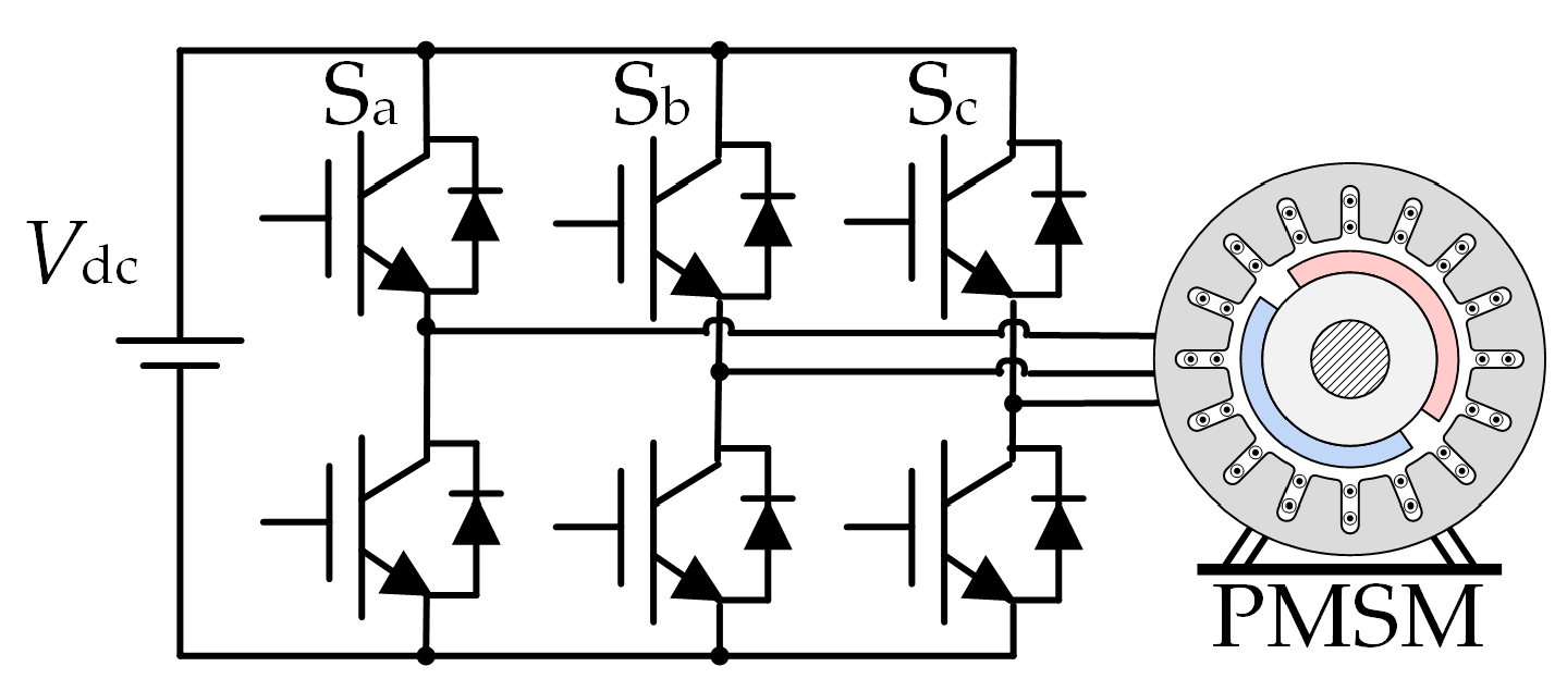
2. Dual-Vector Predictive Model of PMSM

The two-level voltage source inverter-fed PMSM system is shown in Figure 1. Switch variables are defined as Si, i ∈ {a, b, c}, representing the switch state of the inverter bridge arm switch tube:
S i = { 1 ,   upper   switch   tube   ON , lower   switch   tube   OFF 0 ,   upper   switch   tube   OFF , lower   switch   tube   ON
According to the above definition, there are eight optional switch states in total, corresponding to 8 voltage vectors Vm (m ∈ {0, 1, 2, 3, 4, 5, 6, 7}). Among them, V1V6 are effective vectors, V0 and V7 are zero vectors.
The voltage equations of the PMSM in dq frame are expressed as:
{ u sd = R s i sd + d ψ sd d t ω r ψ sq u sq = R s i sq + d ψ sq d t + ω r ψ sd
where usd, usq, isd, isq, ψsd, and ψsq are d-axis and q-axis component of stator voltage, stator current and stator flux, respectively; ωr is the rotor electrical angular speed; Rs is the stator resistance.
The flux and torque equations are as:
{ ψ sd = L d i sd + ψ f ψ sq = L q i sq
T e = 3 2 p ( ψ sd i sq ψ sq i sd )
where ψf is the rotor flux; Ld, Lq are d-axis and q-axis inductance respectively; Te is the electromagnetic torque; p is pole pairs of motor.
According to the Equations (1) and (2), the stator current is selected as a state variable, and the state-space equation of motor can be obtained. Discretizing the state-space equation, then the stator current predictive model is obtained as:
{ i sd ( k + 1 ) = ( 1 R s T s L d ) i sd ( k ) + T s L d ω r L q i sq ( k ) + 1 L d [ t 1 u 1 s d ( k ) + ( T s t 1 ) u 2 s d ( k ) ] i sq ( k + 1 ) = ( 1 R s T s L q ) i sq ( k ) T s L q [ ω r L d i sd ( k ) + ω r ψ f ] + 1 L q [ t 1 u 1 s q ( k ) + ( T s t 1 ) u 2 s q ( k ) ]
where Ts is the control period of the system; isd (k), isq (k), isd (k + 1) and isq (k + 1) are d-axis and q-axis components of stator current at kTs and (k + 1) Ts, respectively; u1sd (k), u1sq (k), u2sd (k), u2sq (k) are d-axis and q-axis stator voltage of the two voltage vectors at kTs respectively; t1 ∈ [0, Ts] is the action time of the first voltage vector.
Combining (2) and (3), the stator flux predictive model and the torque predictive model are obtained as:
{ ψ sd ( k + 1 ) = L d i sd ( k + 1 ) + ψ f ψ sq ( k + 1 ) = L q i sq ( k + 1 )
T e ( k + 1 ) = 3 2 p [ ψ s ( k + 1 ) × i s ( k + 1 ) ]
where ψsd(k + 1), ψsq(k + 1) are d-axis and q-axis stator flux at (k + 1) Ts respectively; ψs (k + 1), is (k + 1), Te(k + 1) are stator flux, stator current, and electromagnetic torque at (k + 1)Ts respectively.

3. Dual-Vector Predictive Torque Control Based on Candidate Vector Table

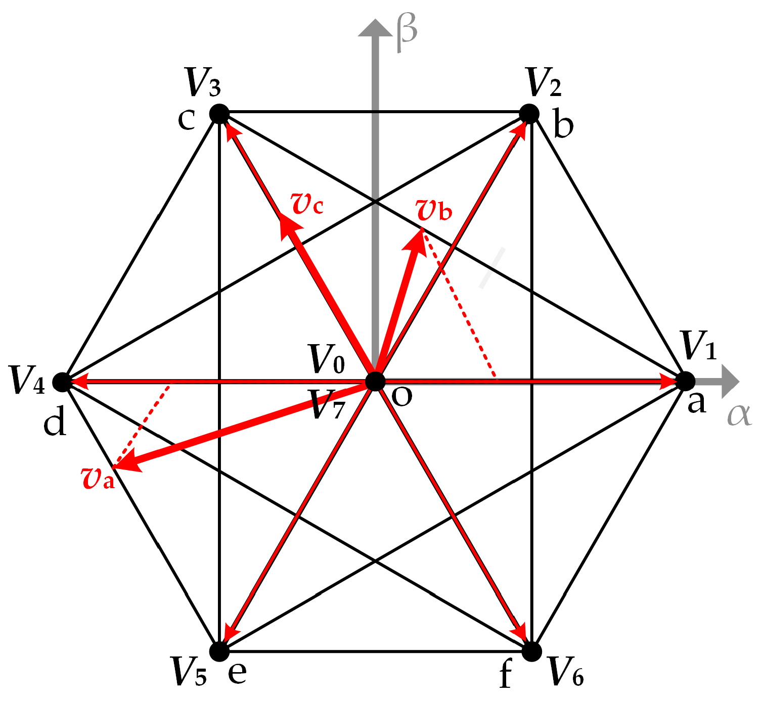
3.1. Synthesized Vector Set

After combining basic voltage vectors to generate synthesized vectors, the action vector combination in one control period can be either an effective-zero combination or an effective-effective combination. The two basic voltage vectors in the combination are expressed as (Vm, Vn), m, n ∈ {0, 1, 2, 3, 4, 5, 6, 7}. There are 28 combinations without considering the sequence of the two vectors. It is worth noting that, given the principle of the minimum action times of the inverter bridge arm, some of these combinations are unreasonable. For example, (V1, V7) can be replaced by (V1, V0) with the same effect but fewer action times of inverter bridge arm, and two opposite voltage vectors (V1, V4) can be replaced by one effective vector and one zero vector. There are 18 reasonable combinations of voltage vectors. Provided different duty cycles, these combinations can generate an infinite number of voltage vectors, which are denoted as synthesized vectors v = dVm + (1 − d) Vn, where the duty cycle d ∈ [0,1]. The collection of terminals of these synthesized vectors constitutes 18 lines as shown in Figure 2. These lines include six sides of the regular hexagon ‘abcdef’, three sides of the triangle ‘ace’, three sides of the triangle ‘bdf’, and six line segments ‘ao’, ‘bo’, ‘co’, ‘do’, ‘eo’, ‘fo’.
(1) If the synthesized vector terminal is on the regular hexagon ‘abcdef’, the two basic voltage vectors (Vm, Vn) of this synthesized vector satisfy the following relationship:
n = { m + 1 , m = 1 , 2 , 3 , 4 , 5 1 , m = 6
For example, in Figure 2, the terminal of the synthesized vector va = daV4 + (1 − da) V5 is on the ‘de’ of the regular hexagon.
(2) If the synthesized vector terminal is on the triangle ‘ace’ or ‘bdf’, the two basic voltage vectors (Vm, Vn) of this synthesized vector satisfy the following relationship:
n = { m + 2 ,   m = 1 , 2 , 3 , 4 m 4 , m = 5 , 6
For example, the terminal of synthesized vector vb = dbV1 + (1 − db)V3 is on the ‘ac’ of triangle ‘ace’.
(3) If the synthesized vector terminal is on any of the line segments ‘ao’, ‘bo’, ‘co’, ‘do’, ‘eo’, ‘fo’, the two basic voltage vectors (Vm, Vn) of this synthesized vector satisfy the following relationship:
n = { 0 ,   m = 1 , 3 , 5 7 , m = 2 , 4 , 6
For example, the terminal of synthesized vector vc = dcV3 + (1 − dc)V0 is on the line segment ‘co’.
After the abovementioned vector synthesis process, voltage vectors in the synthesized vector set are increased to an infinite number. The following is to construct a candidate voltage vector table containing duty cycle information. The voltage vector acted on the inverter is determined by a two-step screening method.

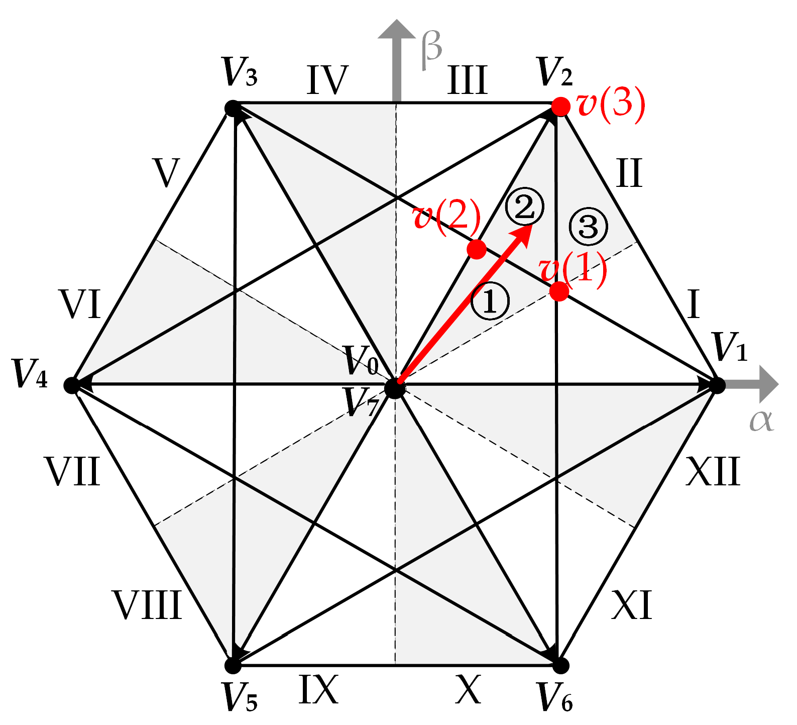
3.2. Desired Voltage Vector

According to the principle of torque and flux deadbeat, the desired voltage vector can be obtained and denoted as D-VV (desired-voltage vector). The process of solving the desired voltage vector is as follows [35,36].
According to the mathematical model of the motor, the change rate of torque can be expressed as:
d T e d t = 3 2 p { u sd ψ sq L d L q L d L q + u sq ( L d L q ) ψ sd + L q ψ f L d L q + ω L d L q [ ( L q L d ) ( ψ sd 2 ψ sq 2 ) L q ψ sd ψ f ] + R s ψ sq L d 2 L q 2 [ ( L q 2 L d 2 ) ψ sd L q 2 ψ f ] }
Discretize Equation (10), and let Te (k + 1) be equal to the torque reference value T e ref , the torque deadbeat line equation is obtained as:
u sq ( k ) T s = M u sd ( k ) T s + B
where:
M = ( L q L d ) ψ sq ( k ) ( L d L q ) ψ sd ( k ) + L q ψ f
B = ( L d L q ( L d L q ) ψ sd ( k ) + L q ψ f ) { 2 ( T e ref T e ( k ) ) 3 p ω r T s L d L q [ ( L q L d ) ( ψ sd 2 ( k ) ψ sq 2 ( k ) ) L q ψ sd ( k ) ψ f ] R s ψ sq ( k ) L d 2 L q 2 [ ( L q 2 L d 2 ) ψ sd ( k ) L q 2 ψ f ] }
The voltage model Equation (1) is discretized by Euler method. By neglecting the resistance term and decoupling the cross coupling term, the stator flux can be approximately discretized as [36]:
[ u sd ( k ) T s + ψ sd ( k ) ] 2 + [ u sq ( k ) T s + ψ sq ( k ) ] 2 = | ψ s ( k + 1 ) | 2
Let |ψs (k + 1)| be equal to the flux reference value |ψsref|, then the flux deadbeat circle equation can be obtained as:
[ u sd ( k ) T s + ψ sd ( k ) ] 2 + [ u sq ( k ) T s + ψ sq ( k ) ] 2 = | ψ s ref | 2
Combining Equations (11) and (15), the voltage vector that meets the inverter voltage limit can be obtained as:
{ u sd ( k ) T s = h + h 2 i j i u sq ( k ) T s = M ( h + h 2 i j i ) + B
where:
h = ψ sd ( k ) + M B + M ψ sq ( k )
i = M 2 + 1
j = ψ sd ( k ) 2 + [ B + ψ sq ( k ) 2 ] | ψ s ref | 2
Translating (16) from synchronous dq coordinate to stationary αβ coordinate, there is:
[ u s α ( k ) u s β ( k ) ] = [ cos θ sin θ sin θ cos θ ] [ u sd ( k ) u sq ( k ) ]
where u (k) and u (k) are the D-VV inαβ coordinate; θ is the rotor position angle.
The space position angle of the DB-VV is:
θ D - VV = arctan u s β ( k ) u s α ( k )

3.3. Construct Candidate Vector Table Offline

The vectors in the synthesized vector set are screened according to the amplitude and position angle of the desired voltage vector. First, the space region of the synthesized vector set is divided into 12 large sectors, numbered I–XII. The region division rule is shown in Figure 3. The 18 line segments formed by the synthesized vector terminals in the set divide each large sector into three small right triangle regions with equal areas, as shown by ①②③ in the sector II. Thus, the region of the synthesized vector set can be divided into 36 small right triangle regions with equal areas.
The duty cycle of the voltage vector corresponding to the vertex of each small right triangle region can be directly obtained by geometric relationship. The voltage vectors corresponding to the three vertexes are taken as the candidate voltage vectors. Taking Figure 3 as an example, if Equation (21) yields a desired voltage vector located in the sector II, the specific position of the desired voltage vector is identified by the amplitude information of desired voltage vector as follows.
When the desired voltage vector satisfies:
{ u s α < u dc 3 u s β < 2 3 3 u dc u s α 3
Then the desired voltage vector is located in region ①;
When the desired voltage vector satisfies:
{ u s α < u dc 3 u s β 2 3 3 u dc u s α 3
Then the desired voltage vector is located in region ②;
When the desired voltage vector satisfies:
{ u s α u dc 3 u s β 2 3 3 u dc 3 u s α
Then the desired voltage vector is located in region ③;
When the desired voltage vector is located in other regions, the calculation method is similar. Merely the region in the first quadrant needs calculating, for the other quadrants have a symmetric relationship with the first one. Without loss of generality, when the voltage vector is located in the small region ② in the sector II, V2 can be determined, and the three sets candidate voltage vectors are denoted as v(1), v(2), v(3) respectively, with duty cycles directly obtained according to the geometric relationship: v(1) = (2/3)V2 + (1/3)V6, v(2) = (1/2)V2 + (1/2)V7, v(3) = V2. Then, 3 sets candidate voltage vectors are substituted into the predictive model. Finally the voltage vectors minimize the cost function are selected. Table 1 is a candidate voltage vector table which contains the duty cycle information when the desired voltage vector is in regions I, II, III of the first quadrant.

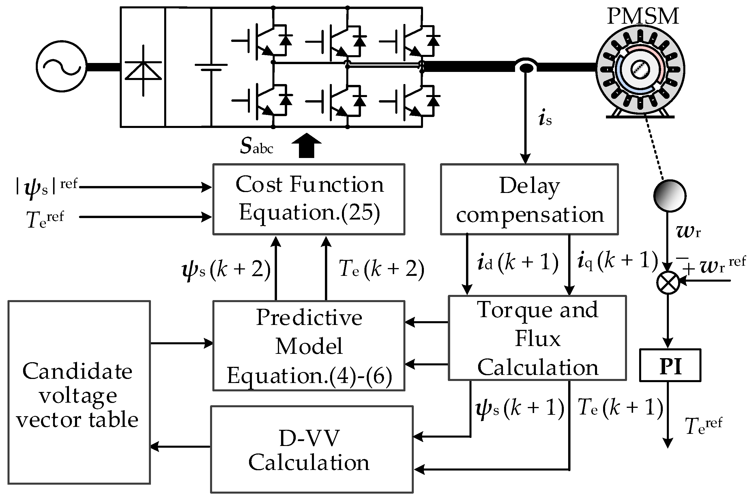
3.4. Realization of Control Algorithm

The control block diagram of the proposed strategy is shown in Figure 4. It mainly includes following parts: delay compensation [37,38], torque and flux calculation, judgment of the region where the D-VV is located on, candidate voltage vector table, predictive model and cost function. The implementation process of algorithm is as follows:
(1)
The stator three-phase current, DC bus voltage and motor rotor position at the current time are obtained by sampling.
(2)
The isd (k + 1) and isq (k + 1) are calculated by using the sampled current values isd (k) and isq (k) according to Equation (4).
(3)
The ψs (k + 1) and Te (k + 1) are calculated by using the compensated current value isd (k + 1) and isq (k + 1). Output the variable at (k + 1) Ts to the predictive model part as the predicted starting value;
(4)
The ψs (k + 1) and Te (k + 1) are also taken as the input of the D-VV calculation part. The D-VV is obtained by the deadbeat principle of torque and flux, and then the region is judged according to its position angle and amplitude information.
(5)
Three sets of candidate voltage vectors and their duty cycles can be obtained by looking up the table. Finally, the candidate voltage vectors and their duty cycles are substituted into the predictive model of PMSM, and the voltage vector acted on the inverter is screened by cost function.
The cost function is defined as:
J = | T e ref T e ( k + 2 ) | + λ Ψ | | ψ s ref | | ψ s ( k + 2 ) | |
where Te (k + 2) and ψs (k + 2) are the predictive values of the electromagnetic torque and stator flux at (k + 2) Ts; λΨ is weight coefficient, its value is tuned empirically based on the branch and bound principle [39], and it is set to 600.

4. Experimental Results

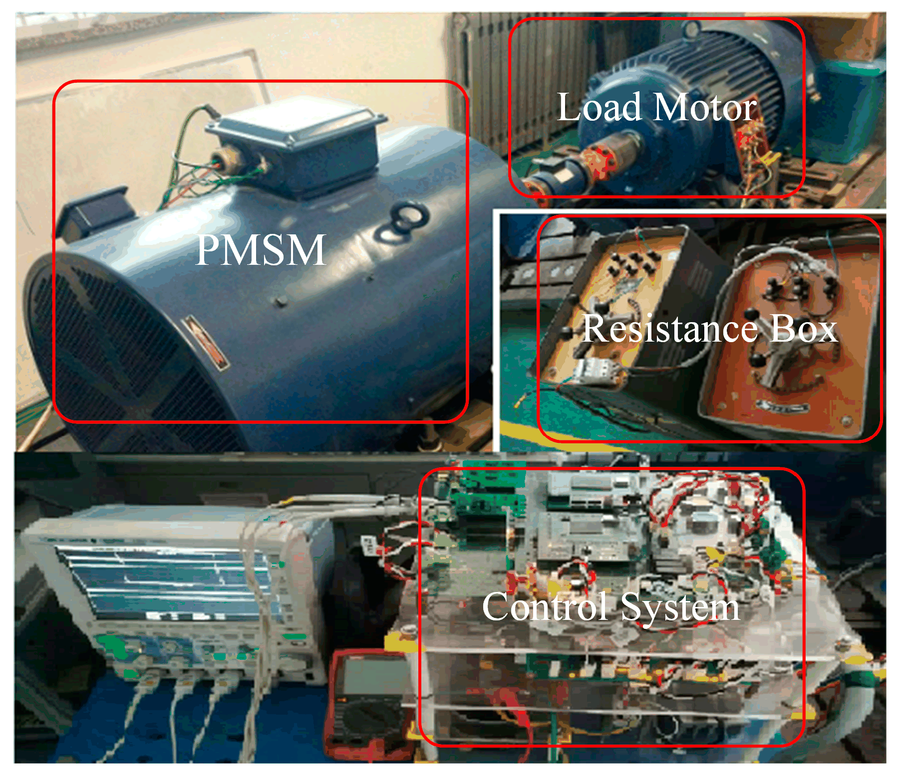
4.1. Experimental Platform

The proposed control strategy is experimentally tested on a 5.2 kW two-level voltage source inverter-fed PMSM system, and the experimental platform is shown in Figure 5. The control system is mainly composed of a control circuit and a power circuit. The cores of the control circuit are TI’s floating-point digital signal processor (DSP) chip TMS320F28335 and field programmable gate array (FPGA) chip EP1C6. The DSP chip is mainly used to sample DC bus voltage, three-phase stator current and realize the control algorithm of PMSM. The FPGA chip is an auxiliary control unit, which is mainly used to realize the adjustment of the encoder interface circuit and the output signal. In addition, the control circuit also includes some peripheral circuits, such as AD conversion, Butterworth filter, dead band, sampling circuit, drive protection circuit and so on. The power circuit mainly includes: voltage stabilizing capacitor, uncontrollable rectifying circuit, and IPM driving circuit of inverters. The input terminal of the control system is connected with an uncontrollable rectifier bridge by the grid and the output terminal is connected with the PMSM by an intelligent power module (IPM) power module. In the experiment, the control of the PMSM is realized by controlling the action of the switching tube in the IPM power module. The load consists of a generator and a resistance box. In the experiment, the load torque is adjusted by adjusting the resistance value of resistance box. PMSM parameters are listed in Table 2.
To prove the proposed method effective, torque and flux amplitude tracking experiments are carried out first, then comparison experiments concerning steady-state and dynamic performance are carried out, with traditional FCS-PTC and Duty-PTC as references. In general, a higher average switching frequency leads to better control performance. Therefore, the switching frequencies of the proposed strategy and FCS-PTC have to be roughly consistent for the experimental results to be tenable. In this regard, the control period of the traditional FCS-PTC is set as 100 μs, and the control period of the Duty-PTC and the proposed control strategy are set as 150 μs.

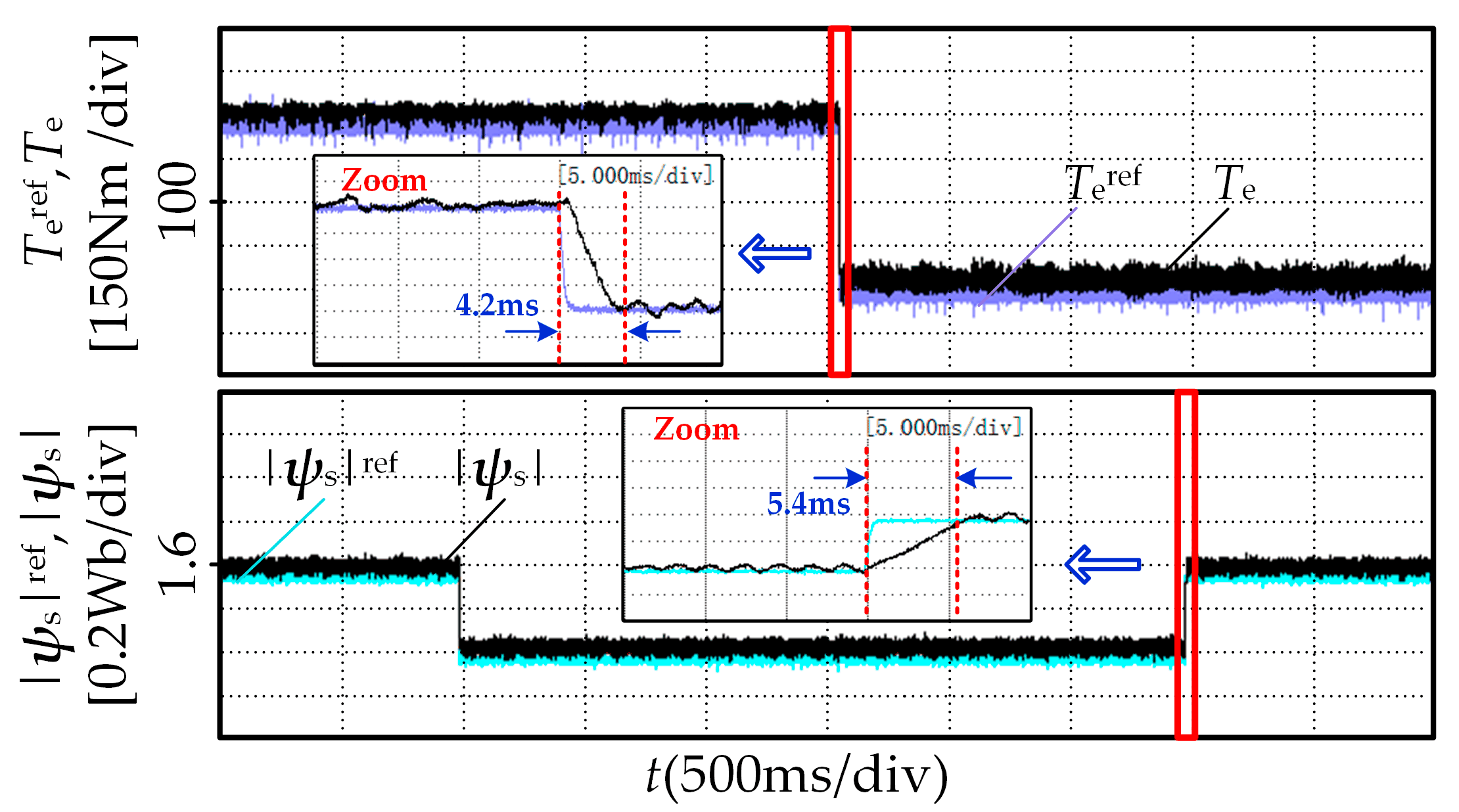
4.2. Torque and Flux Amplitude Tracking Experiment

Torque and flux amplitude tracking performance of the proposed strategy is verified without speed controller as follows. Figure 6 shows the waveforms of torque and stator flux amplitude, where the torque reference value is a step signal from 400 Nm to −200 Nm, and the flux amplitude reference value is also a step signal from 1.6 Wb to 1.2 Wb and then to 1.6 Wb. According to Figure 6, under the proposed strategy, the actual torque and flux are able to track their references rapidly and accurately, when the references change abruptly.

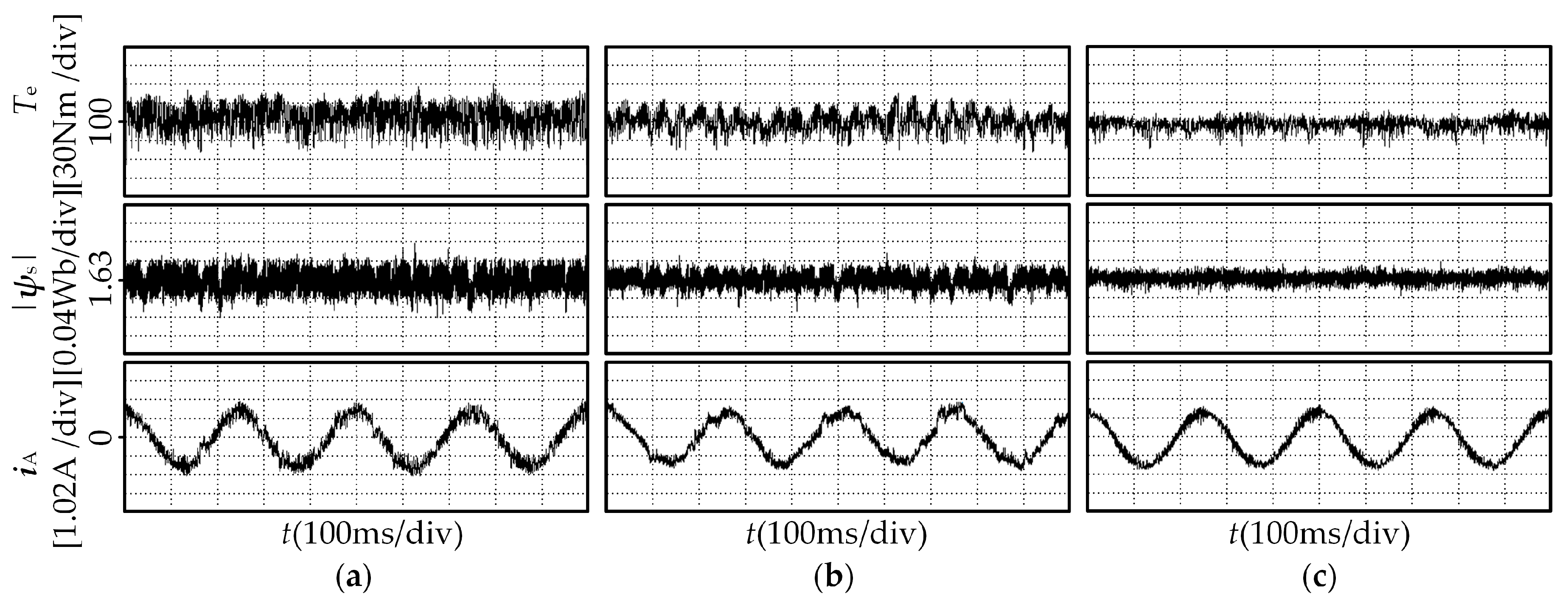
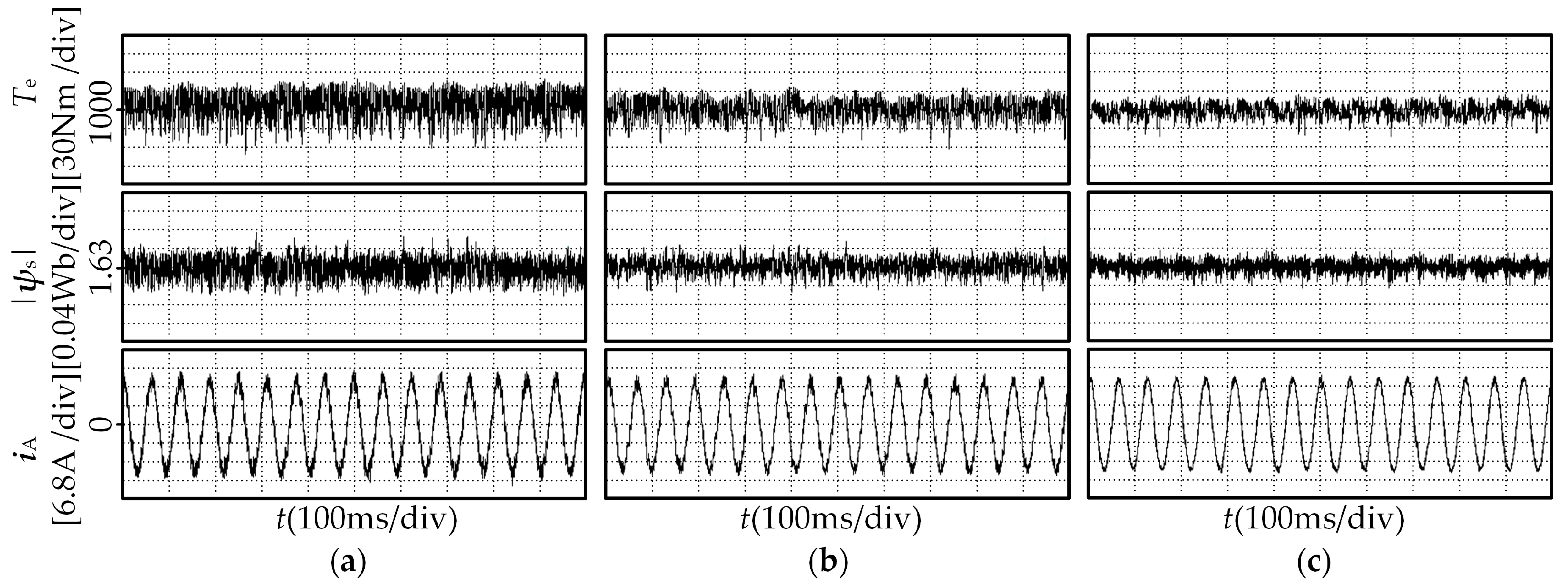
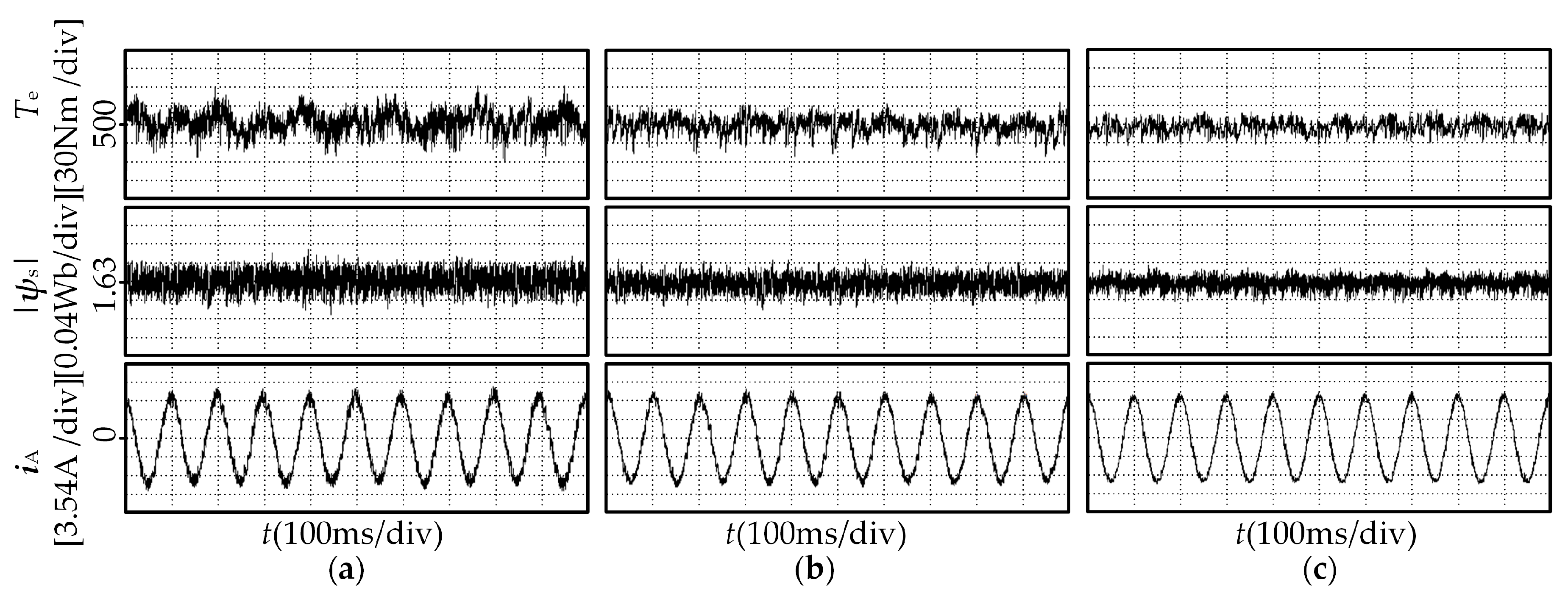
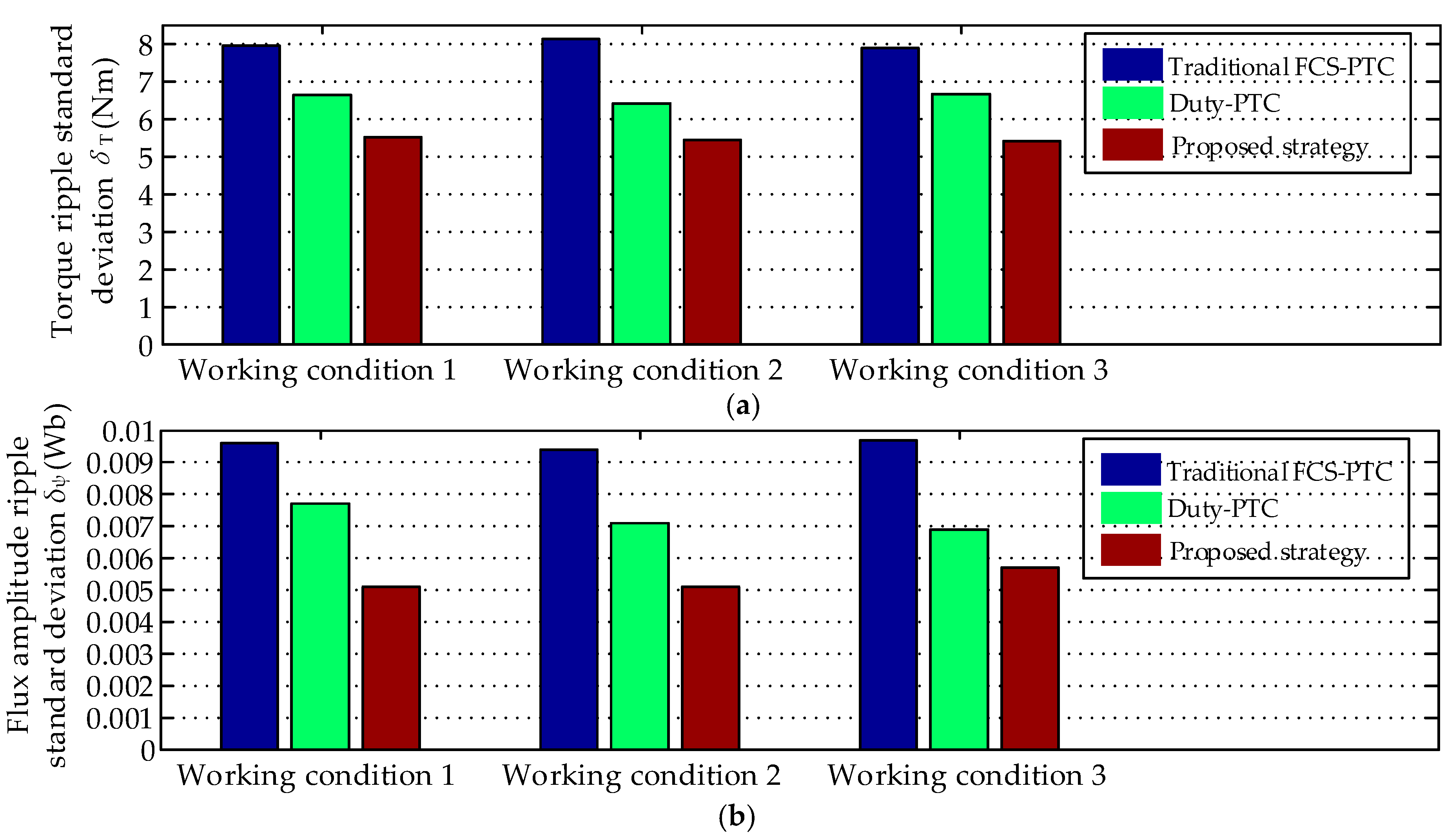
4.3. Steady Performance Comparison

The steady-state performances of the three control strategies are compared under three working conditions. Working condition 1: The motor operates at low speed with light load. The speed and torque are set as 10 r/min and 100 Nm respectively. Working condition 2: The motor operates at medium speed with half load. The speed and torque are set as 25 r/min and 500 Nm respectively. Working condition 3: The motor operates at high speed with full load. The speed and torque are set as 40 r/min and 1000 Nm.
Figure 7, Figure 8 and Figure 9 show the the experimental waveforms of torque, flux amplitude, and phase A stator current under three working conditions of three strategies respectively. According to the waveforms, the proposed strategy causes less torque and flux ripple than the other two. Under the proposed strategy, phase A stator current is closer to an ideal sinusoidal wave. In conclusion, the proposed strategy improves steady-state control performance in contrast to traditional FCS-PTC and Duty-PTC, under low-speed light-load, medium-speed half-load, or high-speed full-load working conditions.

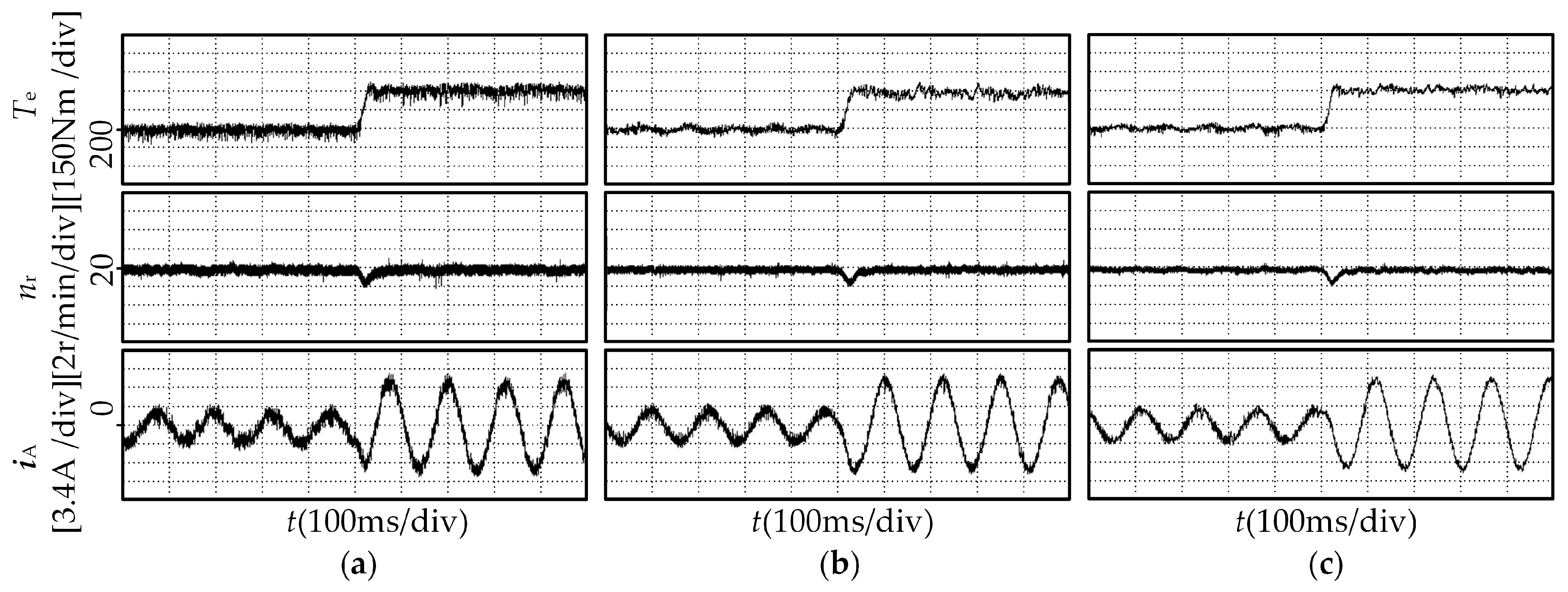
4.4. Dynamic Performance Comparison

Figure 10 shows the experimental waveforms of torque, speed and phase A stator current of three control strategies with speed at 20 r/min and load torque stepping from 200 to 500 Nm. It can be seen that three control strategies can follow the change of load torque rapidly, and the settling time is almost equal. In addition, the proposed strategy has better torque control performance and smoother sinusoidal current waveform, indicating that the proposed control strategy achieves better steady-state control performance and retains the advantages of rapid dynamic response.
Quantitative comparison of three control strategies about the average switching frequencies (favsw), torque ripple standard deviation (δT), flux amplitude ripple standard deviation (δψ) and current harmonic distortion rate (ITHD) are shown in Table 3 (I–III). Table 4 shows the comprehensive comparison of the three control strategies It can be seen that the proposed control strategy can improve the steady-state control performance of the motor with the same average switching frequency as the traditional FCS-PTC’s. Compared with Duty-PTC, the proposed control strategy can obtain higher steady-state control accuracy with lower average switching frequency. The dynamic response time of three control strategies is almost equal, indicating that the proposed strategy preserves the advantage of rapid dynamic response while improving the steady-state control performance of motor. Figure 11 shows histograms of the standard deviation of torque ripple and flux amplitude ripple of three control strategies. According to Figure 11, under working condition 1, compared with the traditional FCS-PTC and Duty-PTC, the torque ripple is reduced by 30.65% and 16.87%, and the flux amplitude ripple is reduced by 46.87% and 33.76% in the proposed control strategy. Under working condition 2, compared with the traditional FCS-PTC and Duty-PTC, torque ripple is reduced by 33.09% and 15.13%, and the flux amplitude ripple is reduced by 45.74% and 28.17% in the proposed control strategy. Under working condition 3, compared with the traditional FCS-PTC and Duty-PTC, the torque ripple is reduced by 31.30% and 18.74%, and the flux amplitude ripple is reduced by 41.24% and 17.39% in the proposed control strategy.

5. Conclusions

In this paper, the two-level inverter-fed PMSM drive system is taken as the research object. By analyzing the characteristics of the synthesized vector set, a dual vector predictive torque control strategy based on the candidate vector table is proposed.
The action vector combination in one control period can be either an effective-zero combination or an effective-effective combination, so that the torque ripple can be effectively reduced. At the same time, the vector combination takes the switching frequency into account, so it can effectively reduce the torque ripple without causing high switching frequency. In this paper, a candidate vector table is constructed offline, and three sets of candidate vectors and their duty cycles can be determined by looking up the table, so the two vectors acted in a control period and their duty cycles can be obtained simultaneously.
Finally, the feasibility and effectiveness of the proposed method are verified on a 5.2 kW two-level inverter-fed PMSM drive system. The experimental results show that, compared with the traditional FCS-PTC and Duty-PTC, the torque and flux amplitude ripples of the proposed strategy are significantly reduced under all of the three working conditions. The dynamic response time of the three control strategies are almost the same.
Although the proposed control strategy is aimed at the two-level inverter-fed PMSM drive system, the future research work can focus on extending the proposed method to other kinds of inverter-fed motor systems to improve the generality of the proposed control strategy. Given the dependence of the PMSM model predictive torque control on the motor parameters, it is necessary to study the robustness of the control system in further researches.

Author Contributions

Y.X., T.S., X.G., and Y.Y. put forward the idea and designed the experiments; Y.X. performed the experiments and analyzed the results; Y.X. and T.S. reviewed and edited the manuscript; all authors contributed to the writing of the paper.

Funding

This research was funded by Major Program of the National Natural Science Foundation of China grant number [51690183] and the Tianjin College Innovation Team Training program of China grant number [TD13-5039].

Conflicts of Interest

The authors declare no conflict of interest.

References

  1. Mohan, D.; Zhang, X.; Foo, G. Three level inverter feddirect torque control of IPMSM with constant switching frequency and torque ripple reduction. IEEE Trans. Ind. Electron. 2016, 63, 7908–7918. [Google Scholar] [CrossRef]
  2. Xia, C.L.; Wang, S.; Gu, X.; Yan, Y.; Shi, T.N. Direct torque control for VSI-PMSM using vector evaluation factor table. IEEE Trans. Ind. Electron. 2016, 63, 4571–4583. [Google Scholar] [CrossRef]
  3. Li, X.; Chau, K.T.; Wang, Y. Modeling of a field-modulated permanent-magnet machine. Energies 2016, 9, 1078. [Google Scholar] [CrossRef]
  4. Mercorelli, P.; Lehmann, K.; Liu, S. Robust Flatness Based Control of an Electromagnetic Linear Actuator Using Adaptive PID Controller. In Proceedings of the 42nd IEEE Conference on Decision and Control, Maui, HI, USA, 9–12 December 2003. [Google Scholar]
  5. Qiao, Z.; Shi, T.; Wang, Y.; Yan, Y.; Xia, C.; He, X. New sliding-mode observer for position sensorless control of permanent-magnet synchronous Motor. IEEE Trans. Ind. Electron. 2013, 60, 710–719. [Google Scholar] [CrossRef]
  6. Mercorelli, P. A motion sensorless control for intake valves in combustion engines. IEEE Trans. Ind. Electron. 2017, 64, 3402–3412. [Google Scholar] [CrossRef]
  7. Liu, H.; Li, S. Speed control for PMSM servo system using predictive functional control and extended state observer. IEEE Trans. Ind. Electron. 2012, 59, 1171–1183. [Google Scholar] [CrossRef]
  8. Deng, W.T.; Xia, C.L.; Yan, Y.; Geng, Q.; Shi, T.N. Online Multi-Parameter Identification of Surface-Mounted PMSM Considering Inverter Disturbance Voltage. IEEE Trans. Energy Convers. 2017, 32, 202–212. [Google Scholar] [CrossRef]
  9. Mercorelli, P. Parameters identification in a permanent magnet three-phase synchronous motor of a city-bus for an intelligent drive assistant. Int. J. Model. Identif. Control 2014, 21, 352–361. [Google Scholar] [CrossRef]
  10. Lesani, M.J.; Mahmoudi, H.; Ebrahim, M.; Varzali, S.; Khaburi, D.A. Predictive torque control of induction motor based on improved fuzzy control method. In Proceedings of the 2013 13th Iranian Conference on Fuzzy Systems (IFSC), Qazvin, Iran, 27–29 August 2013. [Google Scholar]
  11. Geyer, T. Model predictive direct torque control: Derivation and analysis of the state-feedback control law. IEEE Trans. Ind. Appl. 2013, 49, 2146–2157. [Google Scholar] [CrossRef]
  12. Liu, Q.; Hameyer, K. Torque ripple minimization for direct torque control of PMSM with modified FCSMPC. IEEE Trans. Ind. Appl. 2016, 52, 4855–4864. [Google Scholar] [CrossRef]
  13. Xie, W.; Wang, X.C.; Wang, F.X.; Xu, W.; Kennel, R.; Gerling, D. Dynamic loss minimization of finite control set-model predictive torque control for electric drive system. IEEE Trans. Power Electron. 2016, 31, 849–860. [Google Scholar] [CrossRef]
  14. Tian, L.; Zhao, J.; Sun, J. Sensorless control of interior permanent magnet synchronous motor in low-speed region using novel adaptive filter. Energies 2016, 9, 1084. [Google Scholar] [CrossRef]
  15. Xia, C.L.; Qiu, X.D.; Wang, Z.Q.; Shi, T.N. Predictive torque control for voltage source inverter-permanent magnet synchronous motor based on equal torque effect. IET Electr. Power Appl. 2016, 10, 208–216. [Google Scholar] [CrossRef]
  16. Cortés, P.; Kazmierkowski, M.; Kennel, R.; Quevedo, D.; Rodríguez, J. Predictive control in power electronics and drives. IEEE Trans. Ind. Electron. 2008, 55, 4312–4324. [Google Scholar] [CrossRef]
  17. Maeda, T.; Doki, S. Improvement of torque control system of PMSM based on model predictive control. In Proceedings of the 37th Annual Conf. on IEEE Industrial Electronics Society, Melbourne, Australia, 7–10 November 2011. [Google Scholar]
  18. Zhang, Y.C.; Yang, H.T.; Xia, B. Model predictive control of induction motor drives: Torque control versus flux control. IEEE Trans. Ind. Appl. 2016, 52, 4050–4060. [Google Scholar] [CrossRef]
  19. Li, J.; Huang, X.Y.; Niu, F.; You, C.J.; Wu, L.J.; Fang, Y.T. Prediction error analysis of finite-control-set model predictive current control for IPMSMs. Energies 2018, 11, 2051. [Google Scholar] [CrossRef]
  20. Kouro, S.; Cortes, P.; Vargas, R.; Ammann, U.; Rodriguez, J. Model predictive control—A simple and powerful method to control power converters. IEEE Trans. Ind. Electron. 2009, 56, 1826–1838. [Google Scholar] [CrossRef]
  21. Correa, P.; Pacas, M.; Rodriguez, J. Predictive torque control for inverter-fed induction machines. IEEE Trans. Ind. Electron. 2007, 54, 1073–1079. [Google Scholar] [CrossRef]
  22. Rodriguez, J.; Kazmierkowski, M.P.; Espinoza, J.R.; Zanchetta, P.; Abu-Rub, H.; Young, H.A.; Rojas, C.A. State of the art of finite control set model predictive control in power electronics. IEEE Trans. Ind. Inform. 2013, 9, 1003–1016. [Google Scholar] [CrossRef]
  23. Zhang, X.G.; Hou, B.S. Double Vectors Model Predictive Torque Control without Weighting Factor Based on Voltage Tracking Error. IEEE Trans. Power Electron. 2018, 33, 2368–2380. [Google Scholar] [CrossRef]
  24. Zhang, Y.C.; Yang, H.T. Model predictive torque control of induction motor drives with optimal duty cycle control. IEEE Trans. Power Electron. 2014, 29, 6593–6603. [Google Scholar] [CrossRef]
  25. Nui, F.; Li, K.; Wang, Y. Model predictive direct torque control for permanent magnet synchronous machines based on duty ratio modulation. Trans. China Electrotech. Soc. 2014, 29, 20–29. [Google Scholar]
  26. Ren, Y.; Zhu, Z.Q.; Liu, J.M. Direct torque control of permanent magnet synchronous machine drives with a simple duty ratio regulator. IEEE Trans. Ind. Electron. 2014, 61, 5249–5258. [Google Scholar] [CrossRef]
  27. Zhang, Y.C.; Zhu, J.G. Direct torque control of permanent magnet synchronous motor with reduced torque ripple and commutation frequency. IEEE Trans. Power Electron. 2011, 26, 235–248. [Google Scholar] [CrossRef]
  28. Zhang, Y.C.; Yang, H.T. Generalized two-vector-based model predictive torque control of induction motor drives. IEEE Trans. Power Electron. 2015, 30, 3818–3829. [Google Scholar] [CrossRef]
  29. Zhou, Z.Q.; Xia, C.L.; Yan, Y.; Wang, Z.Q.; Shi, T.N. Torque Ripple Minimization of Predictive Torque Control for PMSM with Extended Control Set. IEEE Trans. Ind. Electron. 2017, 64, 6930–6939. [Google Scholar] [CrossRef]
  30. Zhang, Y.C.; Yang, H.T. Two-Vector-Based Model Predictive Torque Control without Weighting Factors for Induction Motor Drives. IEEE Trans. Power Electron. 2016, 31, 1381–1390. [Google Scholar] [CrossRef]
  31. Zhang, Y.C.; Huang, L.L.; Xu, D.L.; Liu, J.L.; Jin, J.L. Performance Evaluation of Two-Vector-Based Model Predictive Current Control of PMSM Drives. Chin. J. Electr. Eng. 2018, 4, 65–81. [Google Scholar]
  32. Abad, G.; Rodriguez, M.Á.; Poza, J. Two-level VSC based predictive direct torque control of the doubly fed Induction machine with reduced torque and flux ripples at low constant switching frequency. IEEE Trans. Energy Convers. 2008, 23, 570–580. [Google Scholar] [CrossRef]
  33. Li, C.; Xia, C.L.; Zhou, Z.Q.; Shi, T.N.; Yan, Y. Torque ripple reduction of permanent magnet synchronous motors based on predictive sequence control. In Proceedings of the 20th International Conference on Electrical Machines and Systems(ICEMS), Sydney, Auatralia, 11–14 August 2017. [Google Scholar]
  34. Vazquez, S.; Aguilera, R.P.; Acuna, P.; Pou, J.; Leon, J.I.; Franquelo, L.G.; Agelidis, V.G. Model predictive control for single-phase NPC converters based on optimal switching sequences. IEEE Trans. Ind. Electron. 2016, 63, 7533–7541. [Google Scholar] [CrossRef]
  35. Wang, Y.L.; Wang, X.C.; Xie, W.; Wang, F.X.; Dou, M.F.; Kennel, R.M.; Lorenz, R.D.; Gerling, D. Deadbeat model-predictive torque control with discrete space-vector modulation for PMSM drives. IEEE Trans. Ind. Electron. 2017, 64, 3537–3547. [Google Scholar] [CrossRef]
  36. Lee, J.S.; Choi, C.H.; Seok, J.K.; Lorenz, R.D. Deadbeat-Direct torque and flux control of interior permanent magnet synchronous machines with discrete time stator current and stator flux linkage observer. IEEE Trans. Ind. Appl. 2011, 47, 1749–1758. [Google Scholar] [CrossRef]
  37. Cortes, P.; Rodriguez, J.; Silva, C.; Flores, A. Delay compensation in model predictive current control of a three-phase inverter. IEEE Trans. Ind. Electron. 2012, 59, 1323–1325. [Google Scholar] [CrossRef]
  38. Zhang, C.; Ma, Q.S.; Cui, T.K.; Zhang, P.M. Model-predictive current control of DC/AC inverters with time delay compensation. In Proceedings of the 2016 IEEE International Conference on Aircraft Utility Systems (AUS), Beijing, China, 10–12 October 2016. [Google Scholar]
  39. Cortes, P.; Kouro, S.; Rocca, B.L.; Vargas, R.; Rodriguez, J.; Leon, J.I.; Vazquez, S.; Franquelo, L.G. Guidelines for weighting factors design in Model Predictive Control of power converters and drives. In Proceedings of the 2009 IEEE International Conference on Industrial Technology, Gippsland, VIC, Australia, 10–13 February 2009. [Google Scholar]
Figure 1. Two-level voltage source inverter-fed PMSM system diagram.
Energies 12 00163 g001
Figure 2. Synthetic vector set.
Energies 12 00163 g002
Figure 3. Space region division of synthesized vector set distribution.
Energies 12 00163 g003
Figure 4. Block diagram of the dual-vector predictive torque control based on candidate vector table.
Energies 12 00163 g004
Figure 5. The experiment platform.
Energies 12 00163 g005
Figure 6. Experimental waveforms of torque and flux amplitude tracking.
Energies 12 00163 g006
Figure 7. The low speed-light load experimental waveforms (a) Traditional FCS-PTC (b) Duty-PTC (c) Proposed strategy.
Energies 12 00163 g007
Figure 8. The medium speed-half load experimental waveforms (a) Traditional FCS-PTC (b) Duty-PTC (c) Proposed strategy.
Energies 12 00163 g008
Figure 9. The high speed-full load experimental waveforms (a) Traditional FCS-PTC (b) Duty-PTC (c) Proposed strategy.
Energies 12 00163 g009
Figure 10. Dynamic experimental waveforms of load toque step change from 200 to 500 Nm (a) Traditional FCS-PTC (b) Duty-PTC (c) Proposed strategy.
Energies 12 00163 g010
Figure 11. Comparisons for traditional FCS-PTC, Duty-PTC and proposed strategy (a) Torque ripple standard deviation δT; (b) Flux amplitude ripple standard deviation δψ.
Energies 12 00163 g011
Table 1. Candidate voltage vector table.
SectorRegionCandidate Voltage Vectors
v(1)v(2)v(3)
I(2/3)V1 + (1/3)V3(1/2)V1 + (1/2)V0V0
(2/3)V1 + (1/3)V3(1/2)V1 + (1/2)V0V1
(2/3)V1 + (1/3)V3(1/2)V1 + (1/2)V2V1
II(2/3)V2 + (1/3)V6(1/2)V2 + (1/2)V7V7
(2/3)V2 + (1/3)V6(1/2)V2 + (1/2)V7V2
(2/3)V2 + (1/3)V6(1/2)V2 + (1/2)V1V2
III(2/3)V2 + (1/3)V4(1/2)V2 + (1/2)V7V7
(2/3)V2 + (1/3)V4(1/2)V2 + (1/2)V7V2
(2/3)V2 + (1/3)V4(1/2)V2 + (1/2)V3V2
Table 2. Parameters of the PMSM.
ParameterSymbolUnitValue
Number of pole pairsp24
Permanent magnet fluxΨfWb1.63
Stator resistanceRsΩ1.89
d-axis inductanceLdmH44.6
q-axis inductanceLqmH46.4
Rated speednNr/min50
Rated torqueTNNm1000
Rated voltageUNV380
Rated currentINA13.5
Table 3. Quantitative comparison.
(I) Quantitative comparison of three control strategies with Figure 7.
ItemTraditional FCS-PTCDuty-PTCProposed Strategy
Working condition 1favsw (kHz)1.612.091.63
δT (Nm)7.966.645.52
δψ (Wb)0.00960.00770.0051
ITHD (%)6.544.964.07
(II) Quantitative comparison of three control strategies with Figure 8.
ItemTraditional FCS-PTCDuty-PTCProposed Strategy
Working condition 2favsw (kHz)1.612.031.61
δT (Nm)8.136.415.44
δψ (Wb)0.00940.00710.0051
ITHD (%)6.364.874.01
(III) Quantitative comparison of three control strategies with Figure 9.
ItemTraditional FCS-PTCDuty-PTCProposed Strategy
Working condition 3favsw (kHz)1.591.941.61
δT (Nm)7.896.675.42
δψ (Wb)0.00970.00690.0057
ITHD (%)6.284.854.01
Table 4. The comprehensive comparison of three control strategies.
ItemTraditional FCS-PTCDuty-PTCProposed Strategy
Comprehensive comparisonSteady performanceworsebetterbest
favsw (kHz)lowhighlow
Dynamic responsefastfastfast
Execution time (μs)466169

