Article

Active Dielectric Window: A New Concept of Combined Acoustic Emission and Electromagnetic Partial Discharge Detector for Power Transformers

by
Wojciech Sikorski
Institute of Electrical Power Engineering, Poznan University of Technology, Piotrowo 3A, 60-965 Poznan, Poland
Energies 2019, 12(1), 115; https://doi.org/10.3390/en12010115
Submission received: 23 November 2018 / Revised: 21 December 2018 / Accepted: 24 December 2018 / Published: 29 December 2018
(This article belongs to the Special Issue Power Transformer Condition Assessment)

Abstract

:
The detection and location of partial discharge (PD) is of great significance in evaluating the insulation condition of power transformers. This paper presents an active dielectric window (ADW), which is a new concept of combined acoustic emission (AE) and electromagnetic PD detector intended for assembly in a transformer’s inspection hatch. The novelty of this design lies in the fact that all structural components of an ultrasonic transducer, i.e., the matching and backing layer, an active piezoelectric element with electrodes, and electrical leads, were built into a dielectric window. Due to the fact that its construction was optimized for work in mineral oil, it is characterized by much higher sensitivity of PD detection than a general-purpose AE sensor mounted outside a transformer tank. Laboratory tests showed that the amplitude of the AE pulses generated by creeping discharges, which were registered by the ADW, was around five times higher on average than the pulses registered by a commonly used contact transducer. A possibility of simultaneous detection of acoustic and electromagnetic pulses (with an integrated ultra-high frequency (UHF) antenna) is an important advantage of the ADW. It allows for an increase in the reliability of PD detection, the accuracy of defect location, and the effectiveness of disturbance identification. This paper describes in detail the applied methods of designing and modeling the ADW components, the manufacturing process of the prototype construction, and the results of preliminary laboratory tests, in which the detector’s sensitivity as well as the efficiency of the PD source location were evaluated.

1. Introduction

Partial discharge (PD) detection based on an acoustic emission method is an important and widely applied technique for diagnostics of high voltage (HV) power electrical equipment, mainly due to such advantages as (1) the possibility of conducting measurements without the necessity to de-energize an HV device, (2) the possibility of precise location of PD sources, (3) the ease of adjustment to working in an online monitoring mode, or (4) the possibility of identifying the type of insulation defect [1]. Unfortunately, besides unquestionable advantages, the acoustic emission (AE) method has one basic weakness: The relatively low sensitivity of PD detection. This results directly from the physical nature of the PD phenomenon, because only a small part of the energy (estimated at about 5%) of a PD current pulse is transformed into mechanical energy in the form of acoustic emission waves, being mostly ultrasounds in the range from 20 to 300 kHz. The remaining part of electrical energy is transformed mainly into thermal and chemical energy [1,2,3].
Usually, with the AE method, contact piezoelectric transducers, commonly available on the market, are used. They consist of three main parts: Piezoelectric crystal, a matching layer (wear plate), and a backing layer. The ancillary components in an ultrasonic transducer comprise the housing, optional acoustic insulation layers, and electrical leads with a connector (Figure 1). For power transformer diagnostics, the users typically choose transducers with a resonant frequency for longitudinal waves of either 60 kHz or 150 kHz [1,2,4,5]. Transducers with a resonant frequency of 60 kHz guarantee higher sensitivity of PD detection. However, due to the possibility of disturbance occurrences during field measurements, they are mainly preferred for factory and laboratory use. For that reason, most users choose the 150 kHz transducers, which are a compromise between acceptable PD detection sensitivity and immunity to disturbances [2,6,7,8,9].
Ultrasonic transducers are mounted on the external surface of a transformer tank. Unfortunately, this is the main reason for low PD detection sensitivity using the AE method. Assuming that the acoustic impedance of mineral oil is equal to Zoil = 1.28 MRayl, and for a steel transformer tank Zsteel = 46.2 MRayl, then from Equation (1) for transmission coefficient T, it follows that at most 10.5% of AE wave energy passes through the transformer tank wall to the transducer, and the remaining 89.5% is reflected [10]:
T = 4 Z o i l Z s t e e l ( Z o i l + Z s t e e l ) 2
Between the metal transformer tank wall and the piezoelectric element, there is a transducer’s wear plate, a front matching layer made of a material such as high-density alumina or an alumina/epoxy composite. Moreover, the internal and external tank surface is covered with anticorrosive epoxy or polyurethane paint. In effect, the wave may be reflected again due to acoustic impedance mismatch at the interface of the transducer’s front material and painted steel wall.
For long-term installations (e.g., online AE monitoring systems), permanent mounting of ultrasonic transducers is realized by using magnetic holders [2,11,12,13]. Although they provide a very stable and durable mechanical coupling between the transducer and the transformer tank, the magnetic holders can also slightly reduce the sensitivity and bandwidth of the transducer [2]. To ensure an efficient transmission of the AE signal from the tank wall to the piezoelectric element, a wear plate is covered with a film of acoustic couplant (usually glycerin, silicone grease, or propylene glycol) approximately 0.5 mm thick. In the case of long-term installations, an acoustic couplant may be exposed to extreme weather conditions, and after some time it becomes naturally degraded and loses its initial properties. It should be underlined that complete loss and even a too thin layer of acoustic couplant can dramatically decrease the transducer’s sensing capabilities.
Contact ultrasonic transducers mounted on the external walls of a transformer tank may be exposed to a number of types of disturbances, such as environmental noises (e.g., rain, hail, thunderstorms, sandstorms, wind), oil circulating pumps and fan noises, or acoustic signals produced by switching operations in a substation. Therefore, without correlation between the acoustic and electromagnetic signals (e.g., using a high-frequency current transformer or internal ultra-high frequency (UHF) antenna), it is practically impossible to effectively and reliably distinguish between the PD and noise signals [14,15,16].
One may also find solutions where in order to increase the detection sensitivity of AE signals from PD, the ultrasonic transducer is inserted into the interior of a power transformer tank. In this case, the amplitude of recorded AE signals can be even several times higher than for contact transducers. In References [17,18], the construction of a power transformer monitoring system with a combined PD detector consisting of a piezoelectric ultrasonic transducer and a capacitive sensor was presented. The ultrasonic transducer was embedded inside the epoxy cover equipped with a screw with which the transducer was coaxially attached to the dielectric plate. In Reference [19], an interesting design of a combined PD detector, containing in its housing an ultrasonic transducer and a UHF antenna, was presented. The active elements of the detector were embedded at the end of the metal rod, which was inserted into the interior of the power transformer tank through a DN50 or DN80 oil drain valve.
This paper presents a new concept, the active dielectric window (ADW). The idea for this solution lay in the fact that at least one active element in the form of piezoelectric ceramics and remaining structures of an ultrasonic transducer constitute an integral part of a dielectric window. By placing the UHF antenna in the window, we obtained a combined ultrasonic and electromagnetic PD detector.
The general conceptual assumptions of the ADW, as well as its advantages, are in detail discussed in Section 2. In the subsequent sections of the paper, the following issues are described: The applied methods of designing and modeling active dielectric window components (Section 3), the production process of the prototype construction (Section 4), and the results of preliminary laboratory tests, in which the sensitivity of the detector and the possibilities for its application for PD source location were evaluated (Section 5).

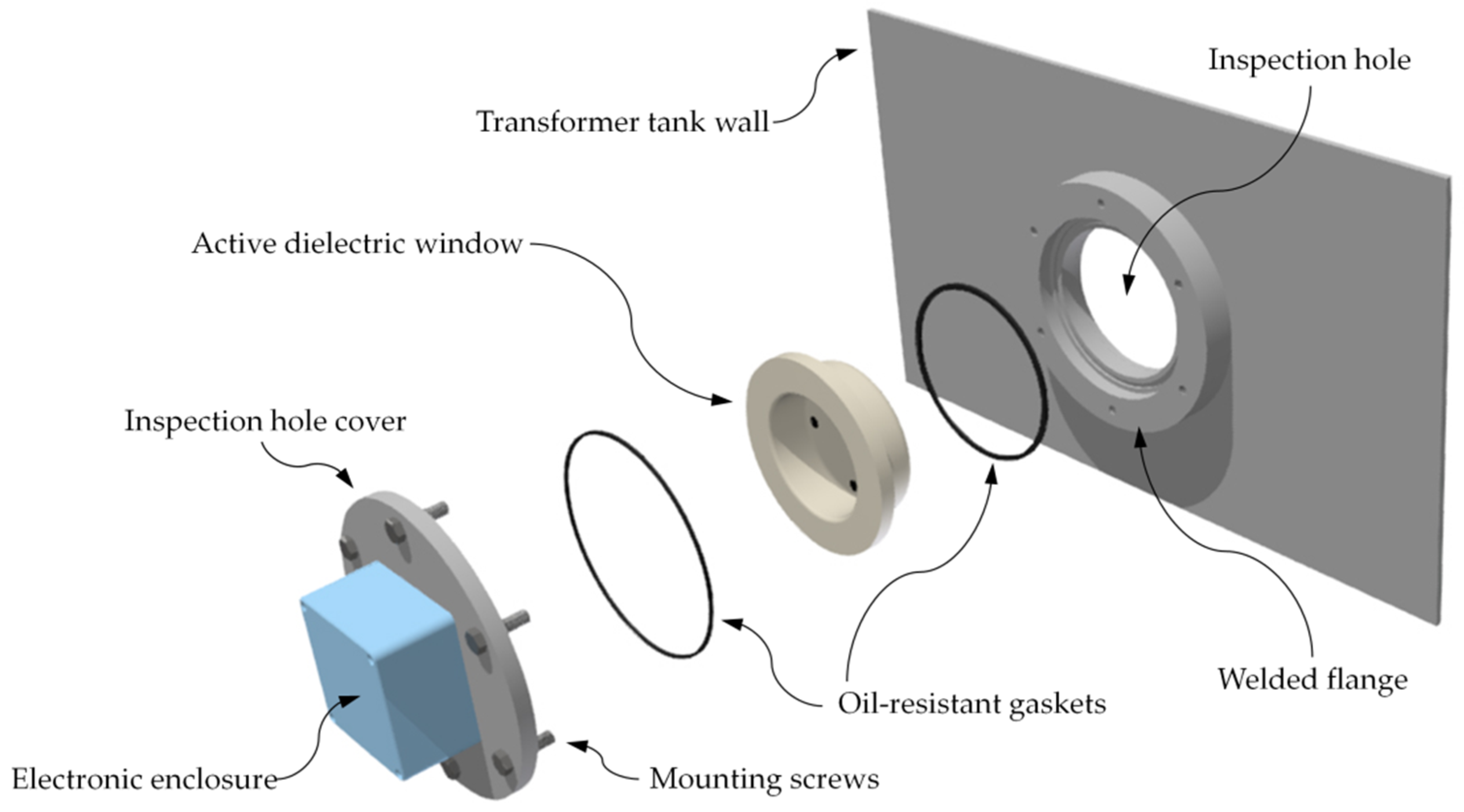
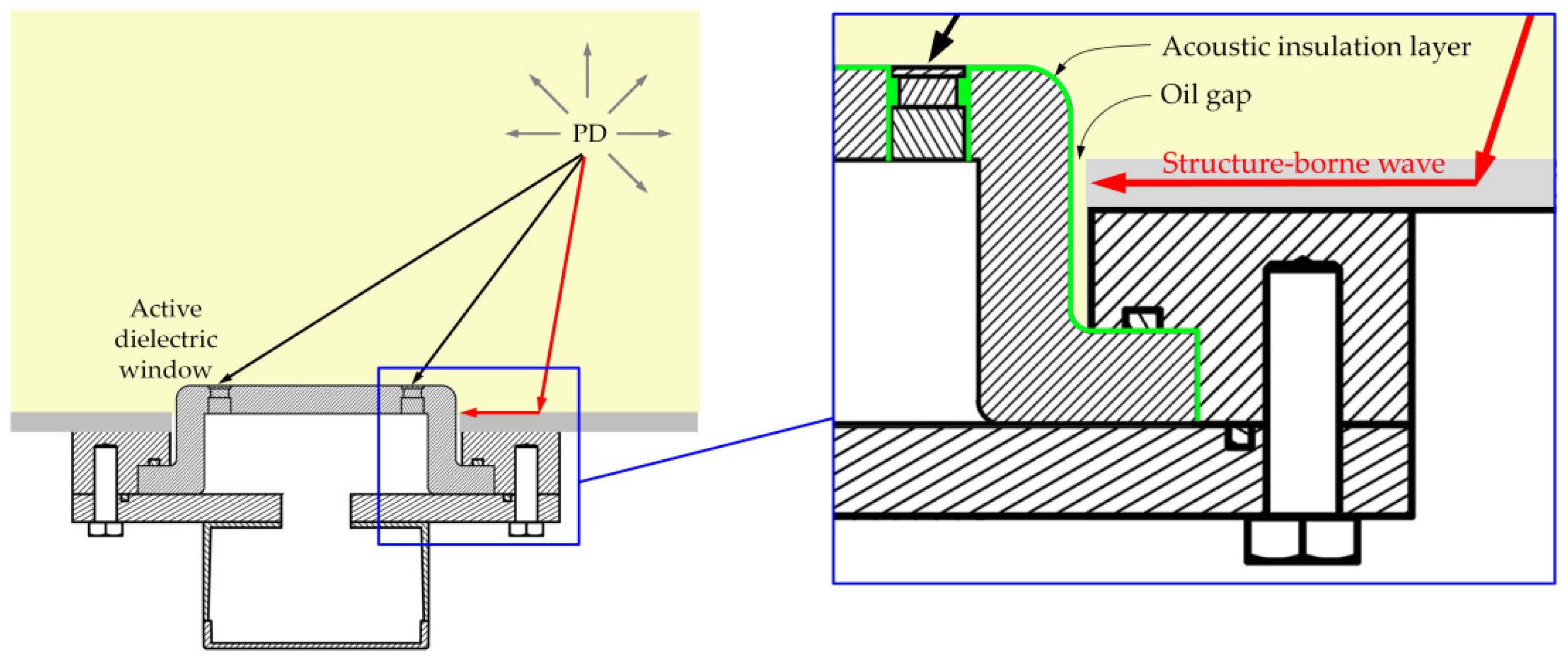
2. General Conceptual Assumptions of the Active Dielectric Window for PD Online Monitoring and Location

Power transformer and reactor tanks, as well as gas-insulated substation (GIS) and gas-insulated line (GIL) housings, are factory-equipped in the inspection hatches. It is typically a round through-hole, around which there is a steel flange with a gasket or O-ring and a cover mounted to the flange with assembly bolts.
The hole in the inspection hatch can be plugged with an element made of a solid dielectric (e.g., high-density alumina ceramics), which in the literature is known as a "dielectric window" [20,21]. A task of the dielectric window is to enable the registration of electromagnetic (EM) waves generated by PD using the electromagnetic detectors, mostly very high frequency (VHF) and ultrahigh frequency (UHF) antennas (Figure 2). This is possible because the dielectric window, contrary to the metal housing of a device, is not a barrier for EM waves of radio frequencies generated by partial discharge.
The design of the ADW was based on four piezoelectric elements equipped in electrodes, electrical leads, and matching and backing layers. The schematic diagram of the active dielectric window is shown in Figure 3.
The ADW was designed to perform two functions simultaneously, that of a detector of AE pulses generated by partial discharges and that of a dielectric window used for UHF antenna mounting.
The possibility of simultaneous application of two different diagnostic techniques (i.e., the AE method and the UHF electromagnetic method) allows an increase in the reliability of PD detection and the effectiveness of disturbance identification, both acoustic and EM (e.g., corona discharge, switching operations at substations, on-load tap-changer operations, Barkhausen noise).
The proposed solution has other advantages as well. In regard to the fact that the ultrasonic transducer is placed inside the tank, its metal wall is not a barrier for ultrasonic waves, as it is in the case of standard, tank-mounted AE sensors. Additionally, the application of a specially designed matching layer in a transducer enables a transfer of acoustic energy from mineral oil (as well as other insulating liquids such as natural or synthetic esters [22,23]) to a piezoelectric element. As a result, the ADW should assure higher sensitivity of detection of AE pulses generated by PDs than a conventional, contact piezoelectric transducer.
An active dielectric window, depending on the indented use, may be produced in various configurations. For online PD monitoring, the simplest configuration with one ultrasonic transducer and a UHF antenna is sufficient. It allows analysis of the intensity of a PD using two methods simultaneously. Apart from discharge detection and monitoring, the ADW may also be used for spatial location of PD sources. For this task, an ADW configuration with at least three ultrasonic transducers and a UHF antenna was intended. PD location is performed using the time difference of arrival (TDOA) technique, which is based on the measurement of delays in the arrival of the AE signal to the ultrasonic transducer relative to that registered by the UHF antenna [24]. To estimate the position of the PD source, it is necessary to register time waveforms of discharges simultaneously with the UHF antenna and three ultrasound transducers. The acquisition of PD waveforms is triggered by a signal coming from the UHF antenna. In turn, in the ADW configuration with four ultrasonic transducers, for location of the PD sources there is no need for the UHF antenna mounting, because time delays are then measured relative to the transducer, which is first to register the pulse (it is a so-called “all-acoustic PD location”) [16].
The way the ADW is mounted in the inspection hatch is identical to the case of a standard dielectric window (Figure 4). Ensuring adequate tightness in order to avoid undesired oil leaks has a fundamental meaning. For that reason, at least two gaskets must be used, where a highly conductive shielding gasket is placed between the welded flange and the inspection hole cover.

3. Designing and Modeling of Active Dielectric Window Components

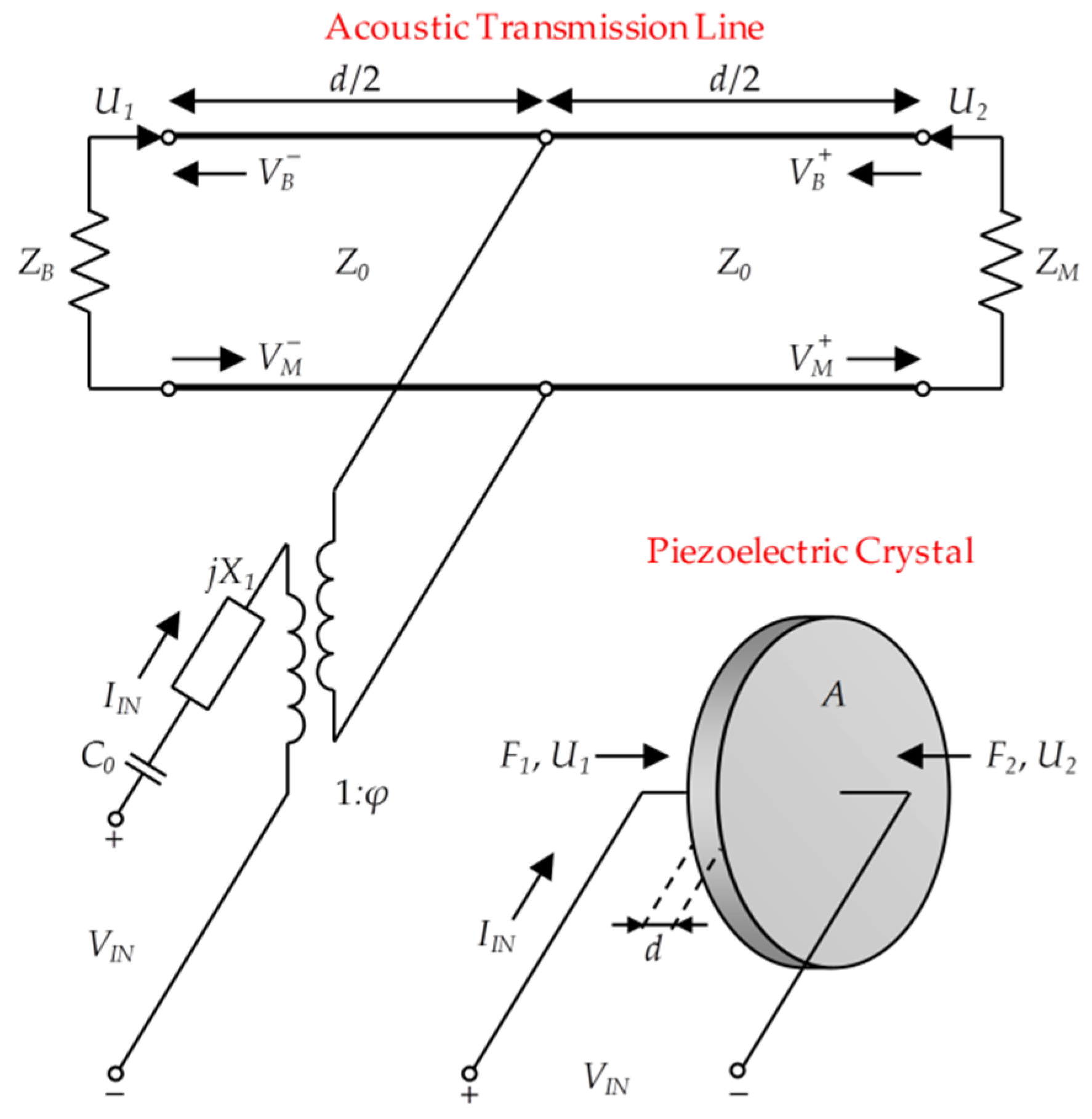
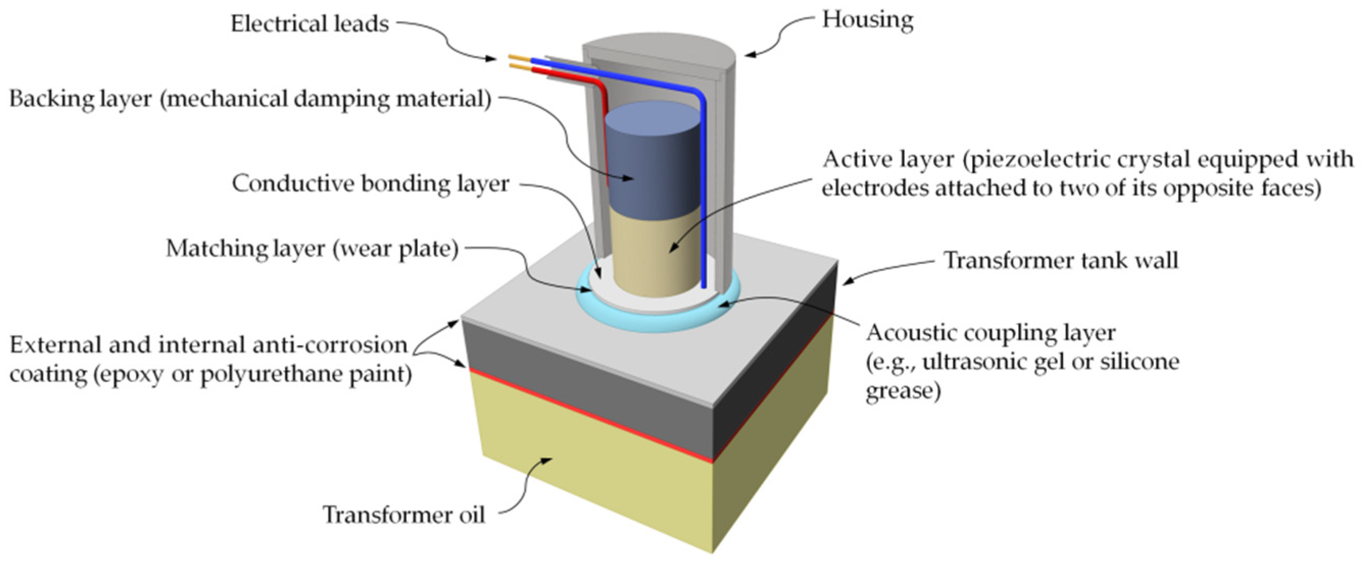
3.1. Mathematical Modeling of Piezoelectric Transducer Structures

Various mathematical models for ultrasonic transducers based on piezoceramic materials have been around for a long time and allow for significantly simplifying and accelerating the design process. A fundamental issue when designing an ultrasonic transducer is the knowledge of the piezoceramic behavior regarding two closely interacting parts: The front/back mechanical side of the ceramic and the electrical part. This electromechanical interaction was first introduced in the form of electrical equivalent circuits by Mason [25]. The developed model, based on network theory, separated the piezoceramic element into an electrical port and two (left and right) acoustic ports through the use of virtual concepts such as negative capacitance and electromechanical transformers. This allowed for describing the behavior of one-dimensional vibrations of a piezoceramic plate, but the introduction of "unphysical" elements into the model has become a source of criticism. Redwood [26] showed that this negative capacitance could be transformed onto the acoustic side of the transformer and treated like a length of acoustic line. Unfortunately, from a physics point of view, the model was still imperfect. Krimholtz, Leedom, and Matthaei [27] developed a new alternative model (commonly referred to as the KLM model), which removed circuit elements between the top of the transducer and the node of the acoustic transmission line. The general structure of the KLM model is shown in Figure 5.
In the KLM model, VIN and IIN are respectively the voltage and current applied to the piezoceramic that produces the resulting acoustic forces F1 and F2. The variables U1 and U2 symbolize the particle velocities at the respective faces of the piezoelectric crystal. The particle velocities inside the crystal are denoted by VB and VM, where the subscript B indicates the backward-traveling acoustic waves propagating toward the backing layer, and the subscript M indicates the forward-traveling acoustic waves propagating toward the matching layer (the plus and minus signs in the superscript mean the left and right halves of the piezoelectric crystal, respectively).
The input parameters include the thickness of the piezoelectric material d, the area of the electrodes A, and the acoustic impedances of the main transducer elements: The piezoelectric crystal Z0, backing layer ZB, and matching layer ZM. Furthermore, the model consists of input electrical reactance X1 and input capacitance C0. The acoustical side of the KLM model is coupled to the electrical side by a transformer with a turns ratio (1:φ). This transformer converts the electrical signal into the appropriate acoustic values. The equations for these parameters are given below:
Z 0 = ρ c A = A ρ c 33 D ,
C 0 = ε 33 S A d ,
X 1 = h 33 2 A ω 2 Z 0 sin ( ω d c ) ,
φ = ω Z 0 2 h 33 sin ( ω d / 2 c ) ,
h 33 = k t c 33 D / ε 33 S ,
where ρ is the density of the piezoceramic material (kg/m3), c is the velocity of longitudinal acoustic waves (m/s), c 33 D is the elastic stiffened for constant electric displacement (N/m2), ε 33 S is the clamped (high-frequency) dielectric constant, φ is the electromechanical transformer ratio of the KLM model, h 33 is the piezoelectric constant (V/m), and k t is the electromechanical coupling factor.
Based on the value of the acoustic impedance (in Rayl or Pa·s/m3) of piezoelectric crystal Z0, matching layer ZM, and backing layer ZB, the input impedances for both layers can be calculated as follows:
Z I N , M = Z 0 Z M + j Z 0 tan ( ω d / 2 c ) Z 0 + j Z M tan ( ω d / 2 c ) ,
Z I N , B = Z 0 Z B + j Z 0 tan ( ω d / 2 c ) Z 0 + j Z B tan ( ω d / 2 c ) .
According to the transmission line theory, the value of the input impedance of the electrical two-port can be determined from Equation (9):
Z I N = 1 j ω C 0 + j X 1 + Z a φ 2 ,
where Z a is the impedance seen looking into the acoustic transmission line,
Z a = Z I N , M Z I N , B Z I N , M + Z I N , B .
ZIN corresponds to the real impedance measured by the impedance analyzer. The minimum impedance frequency on the Z(f) plot is the resonant frequency, at which the piezoceramic element vibrates most readily and most efficiently converts the electrical energy into mechanical energy. In turn, the maximum impedance frequency is also the antiresonance frequency.
In order to determine the pressure radiated by the ultrasonic transducer, which is excited by the voltage VIN, it is necessary to determine the particle velocities U1 and U2:
U 1 = I I N φ ( e j k d 2 Γ M e j k d 2 ) e j k d Γ B Γ M e j k d ( 1 + Γ B )
U 2 = I I N φ ( Γ B e j k d 2 e j k d 2 ) e j k d Γ B Γ M e j k d ( 1 + Γ M )
where k is the wave number in the piezoelectric crystal, and ГB and ГM are the current transmission coefficients given by
Γ B = Z 0 Z B Z 0 + Z B
Γ M = Z 0 Z M Z 0 + Z M
Replacing IIN with VIN and solving for the pressure wave leaving the surface of the piezoelectric crystal gives
P 1 ( ω ) = Z B V I N ( ω ) φ Z I N ( e j k d 2 Γ M e j k d 2 ) e j k d Γ B Γ M e j k d ( 1 + Γ B )
P 2 ( ω ) = Z M V I N ( ω ) φ Z I N ( Γ B e j k d 2 e j k d 2 ) e j k d Γ B Γ M e j k d ( 1 + Γ M ) ,
where P1(ω) and P2(ω) are the pressure waves radiated from the back and front faces of the piezoelectric crystal, respectively. The pulse–echo response can be calculated using the inverse fast Fourier transform (IFFT) of the pressure to generator voltage (PGV) transfer function. The PGV is a function that allows the determination of the pressure propagated from the piezoelectric crystal to the matching layer and subsequently to the medium:
P m P i n , f r o n t = n = 1 n = N Z i n , n + 1 Z i n , n + 1 cos ( ω d 2 c ) + j sin Z n sin ( ω d 2 c )   if   N   1 ,
where Pm is the pressure propagated in the medium, Pin,front is the input pressure from the first front layer, Zn is the acoustic impedance of the front layer under consideration, and Zin,n+1 is the input impedance of the following layer.
All structures of the ultrasonic transducer used for building the prototype of the active dielectric window were designed based on the calculations and simulations performed with the KLM model.

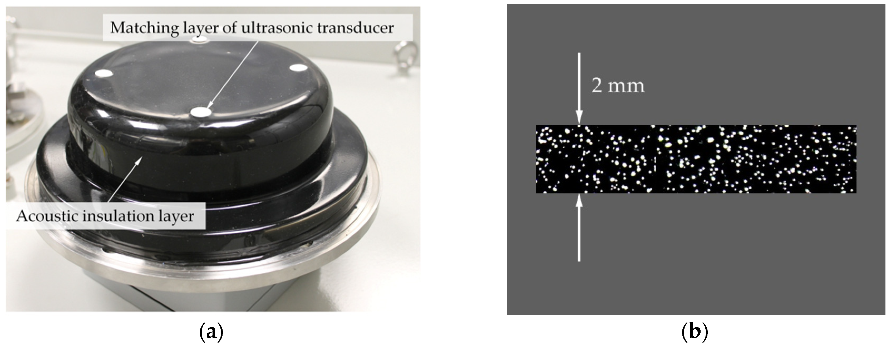
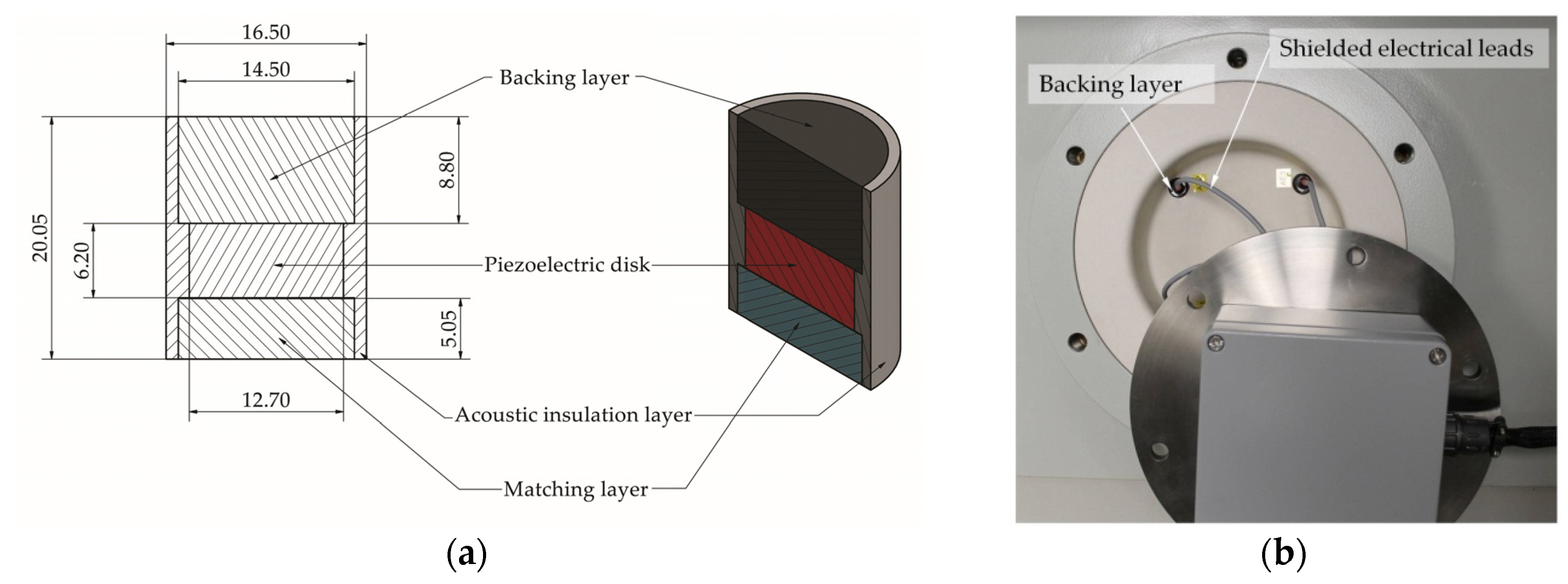
3.2. Matching and Backing Layers

The matching layer in the ultrasonic transducer performs a similar function as the antireflection layer applied to the surface of lenses and other optical devices to reduce light reflection. This element enables acoustic emission wave transfer from a medium, in which the transducer is in contact with the piezoelectric crystal. The greater the role of the matching layer, the bigger the difference between acoustic impedance of the piezoelectric crystal and the ultrasonic medium is.
If we assume that Z0 is an acoustic impedance of piezoelectric material, Zoil is an acoustic impedance of transformer oil, and ZM is an acoustic emission of a matching layer with thickness l (in which the wavelength at the frequency of interest is λl), then the transmission coefficient T for propagation from the transformer oil to the piezoelectric crystal at normal incidence is given as
T = 4 Z 0 Z o i l ( Z 0 + Z o i l ) 2 cos 2 ( 2 π l λ l ) + ( Z M + Z 0 Z o i l Z M ) 2 sin 2 ( 2 π l λ l ) .
Transmission coefficient T takes values from the range between 0 and 1. When T = 1, theoretically lossless transmission of acoustic energy from ultrasonic medium to the piezoelectric crystal occurs. In order to meet this condition, the thickness of the matching layer l has to be equal to λ/4, and then Equation (18) reduces to the form
T = 4 Z 0 Z o i l ( Z M + Z 0 Z o i l Z M ) 2 .
Equation (19) is equal to 1 if the acoustic impedance of the matching layer is the geometric mean of the impedances of transformer oil and the piezoelectric material,
Z M = Z 0 Z M .
Assuming the acoustic impedance of the chosen piezoelectric material equals 31 MRayl, and mineral oil is ~1.28 MRayl (at a temperature of 25 °C), then the optimal value of matching layer acoustic impedance should total 6.30 MRayl. The material used for its manufacturing ought to be oil-resistant, mechanically durable, and resistant to temperature changes. Unfortunately, acoustic impedance of all durable and chemically resistant plastics, such as polyamide (PA6 or glass fiber-reinforced PA66), acrylonitrile butadiene styrene (ABS), or polyoxymethylene (POM), is definitely too low (<4 MRayl). To overcome the limitation of the available materials, base resins such as epoxies or polyurethanes are often filled with high-velocity (e.g., alumina, v ≈ 10,500 m/s) or high-density (e.g., tungsten, ρ ≈ 19,250 kg/m3) powders to fabricate 0–3 composites with the required properties. The elastic properties of such a two-phase composite can be estimated using the Devaney and Levine model, which is based on a self-consistent formulation of multiple-scattering theory [28]. According to this model, the bulk modulus K and the shear modulus G of the composite are given by Equations (21) and (22):
K = K 1 + φ 2 ( 3 K + 4 G ) ( K 2 K 1 ) 3 K + 4 G + 3 ( K 2 K 1 )
G = G 1 + φ 2 5 G ( 3 K + 4 G ) ( G 2 G 1 ) G ( 15 K + 20 G ) + 6 ( K + 2 G ) ( G 2 G 1 )
where K1, G1, K2, and G2 are the bulk and shear moduli of the matrix (epoxy) and powdered material (filler), respectively. The density of a two-phase composite material is calculated as the volume averaged density,
ρ = φ 1 ρ 1 + φ 2 ρ 2
where φ1, ρ1, φ2, ρ2 are the volume fractions and densities of the epoxy and filler, respectively. The longitudinal velocity VL and shear velocity VS of the sound wave are directly related to the mechanical parameters K, G, and ρ of the composite:
V L = K + 4 3 G ρ
V S = G ρ .
Finally, the acoustic impedance for the longitudinal sound wave can be calculated as follows:
Z L = ρ V L .
The acoustic impedance values of epoxy/alumina and epoxy/tungsten composites were calculated from Equations (21)–(26) and are presented in Figure 6 and Figure 7. The parameters used for calculations are collected in Table 1.
The characteristics presented in Figure 6 and Figure 7 show that for the formation of composite materials with an acoustic impedance equal to 6.3 MRayl, one should use approximately 0.16 pu volume fraction of tungsten or 0.38 pu volume fraction of alumina powder. Obviously, regarding low attenuation, the alumina powder is a proper material for manufacturing the matching layer. In turn, an epoxy/tungsten composite, due to high attenuation, is an ideal material for manufacturing the damping layer. In the case of the described PD detector, the backing layer performs four functions: (1) It loads the piezoelectric element, which contributes to reducing its resonance (quickly dampening vibrations), (2) it absorbs the backward-directed ultrasound energy and attenuates the acoustic signals from the housing, and (3) it extends the bandwidth.

3.3. Piezoelectric Element

A piezoelectric element performs the function of a receiver (or transmitter) of ultrasonic signals in a transducer. It is typically made in the form of a disc, cylinder, or ring, and its upper and bottom surface are covered by a thin layer of conductive material, which performs the function of an electrode.
In the proposed ADW solution, a disc made of high-purity lead zirconate titanate (PZT) is an active element. The properties of the ceramics used in this study correspond to the general properties of the PZT-5A (Table 2).

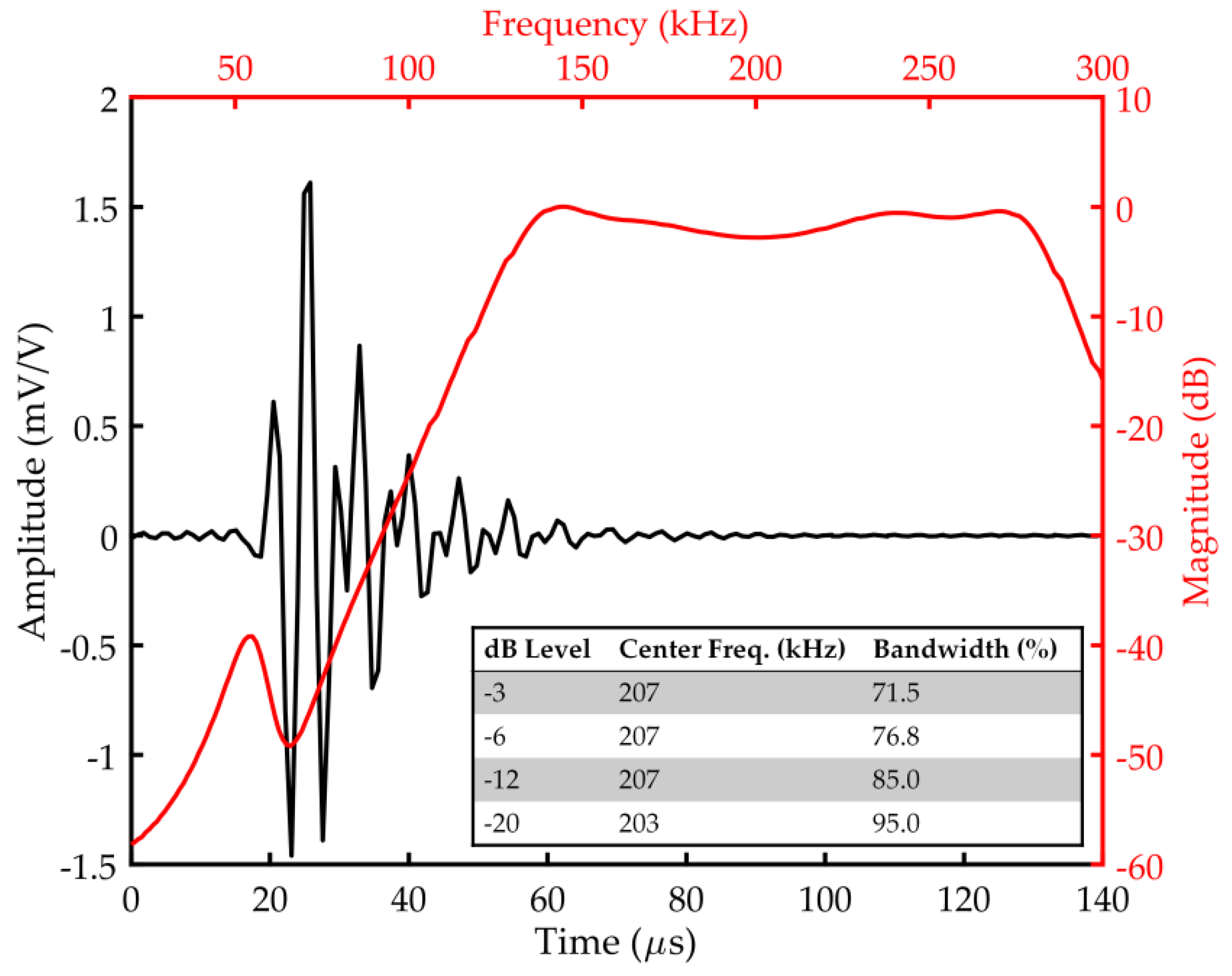
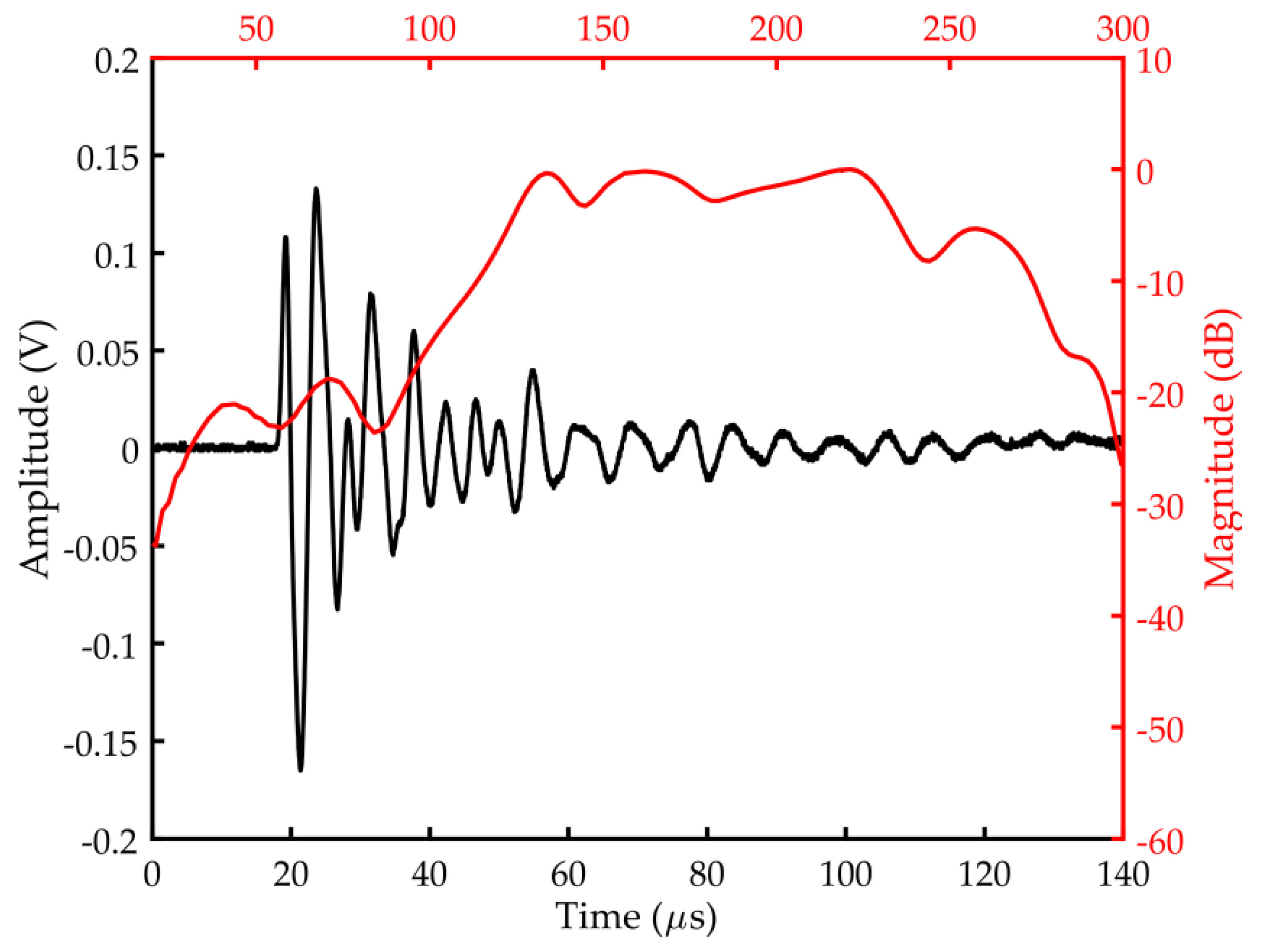
3.4. Frequency Response Modeling of the Piezoelectric Transducer

When starting the frequency response modeling, as a reference point an acoustic emission sensor type PAC R15D (Physical Acoustics, Princeton, USA) was selected, with a resonance frequency of 150 kHz. It has a very good sensitivity and frequency response over the range of 50–400 kHz. The R15D is a differential sensor designed for applications where high-background electrical noise is a major concern. Currently, the R15 series family of AE sensors is one of the most commonly used piezoelectric transducers for PD detection in power transformers.
For designing the transducer components, the following assumptions were made:
  • The first resonance frequency should be similar to the PAC R15D sensor, approximately 150 kHz;
  • The bandwidth should range between ~100 and ~300 kHz, with a central frequency of ~200 kHz;
  • The frequency response curve in the working frequency range ought to be possibly the flattest;
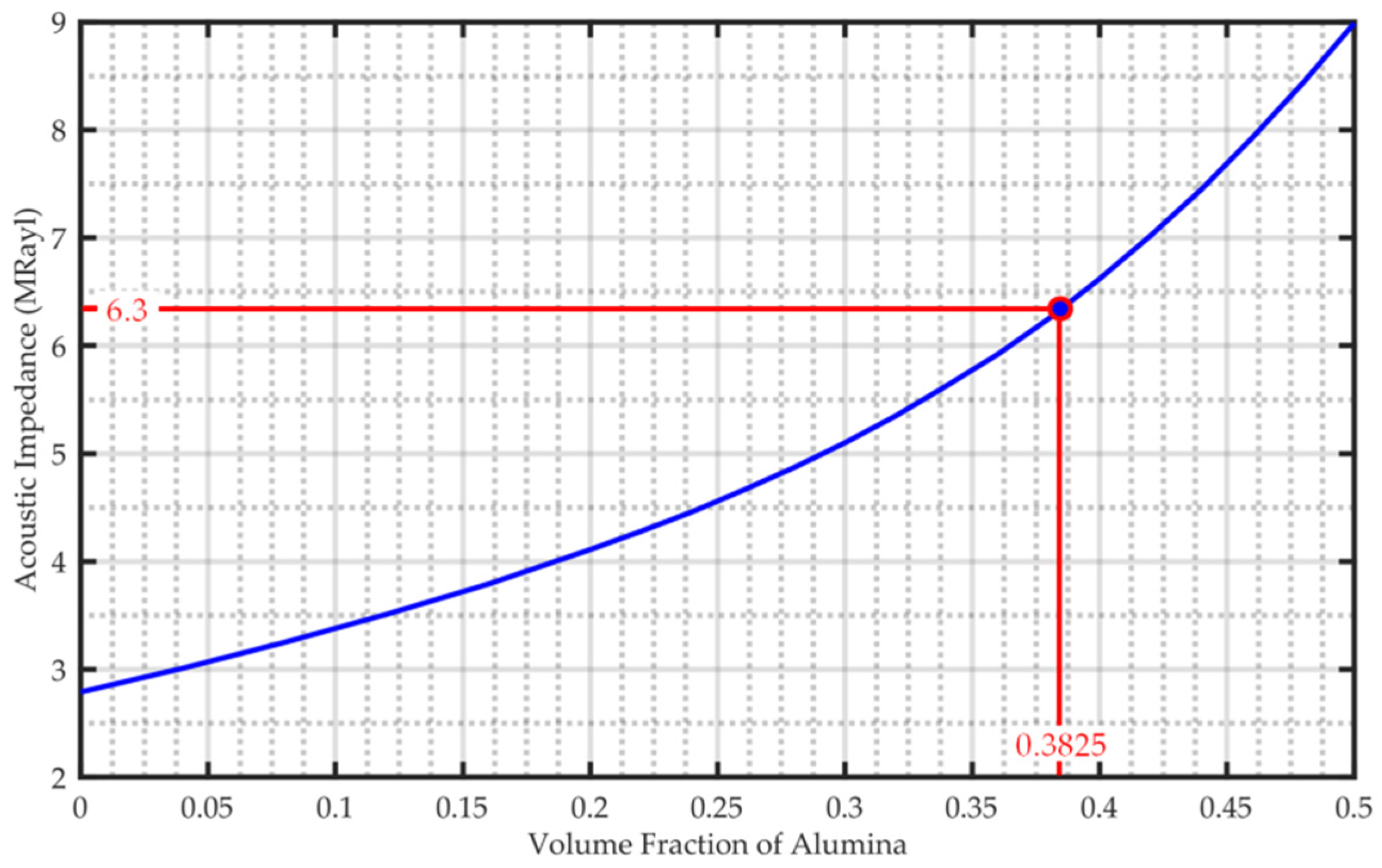
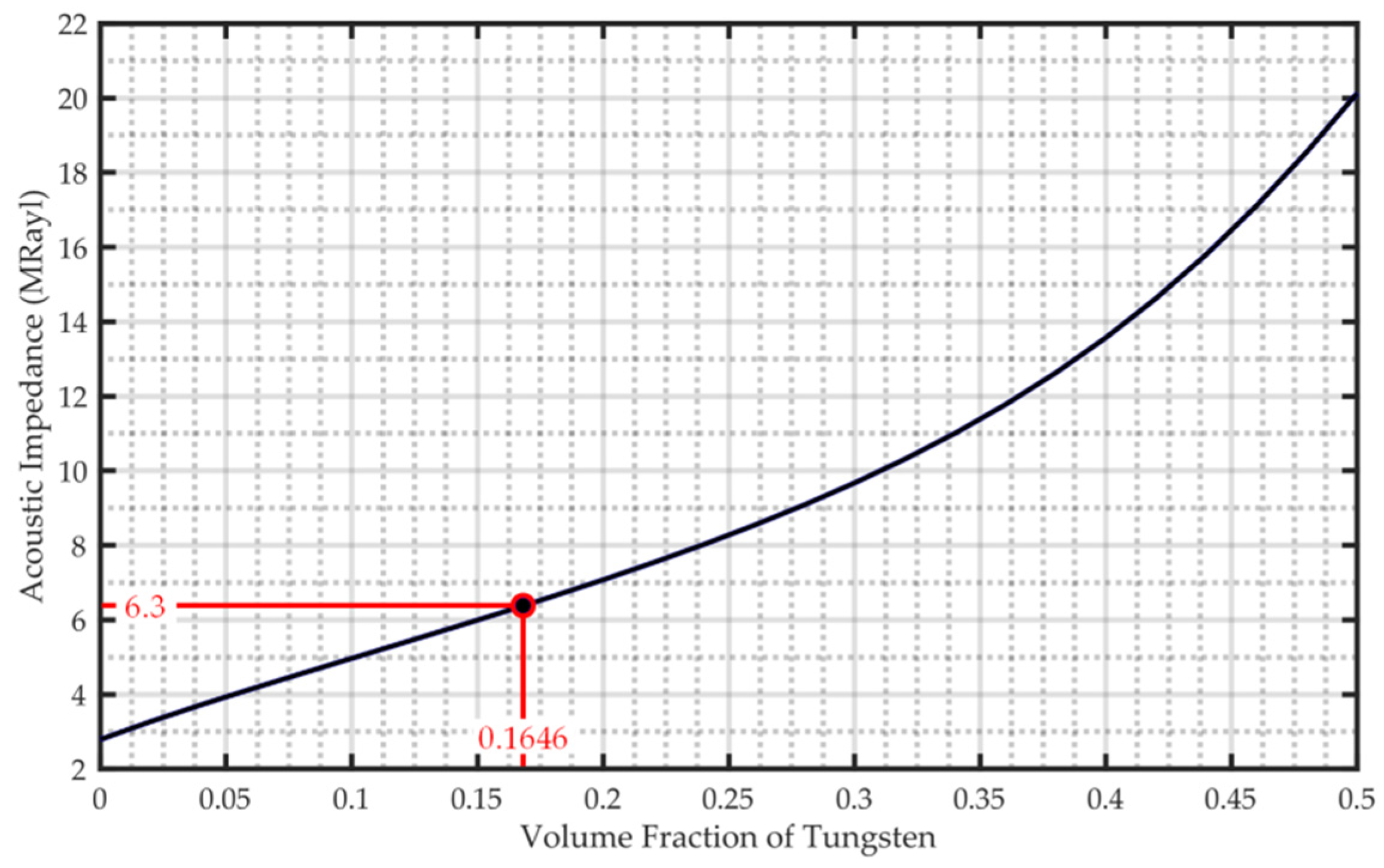
  • To improve the efficiency of energy transmission of the acoustic signal from the oil to the piezoelectric element, the acoustic impedance of the matching layer should total 6.3 MRayl;
  • Because it was earlier assumed that the standard window made of ceramics would have a thickness of 20 mm, then therefore the height of the piezoelectric element should not exceed 15 mm (the remaining space was intended for matching and backing layers).
The assumed resonance frequency and bandwidth in the above specification are compliant with the IEC [11] (p. 28) and IEEE [2] (p. 12) recommendations regarding the selection of AE sensors for the detection of partial discharges in power transformers.
Frequency response curve modeling was made using the KLM model, a detailed description of which was presented in Section 3.1.
The values of geometrical and material parameters, for which both the assumed resonance frequency (145 kHz) and the flat shape of the frequency response curve were obtained (Figure 8), are summarized in Table 3.

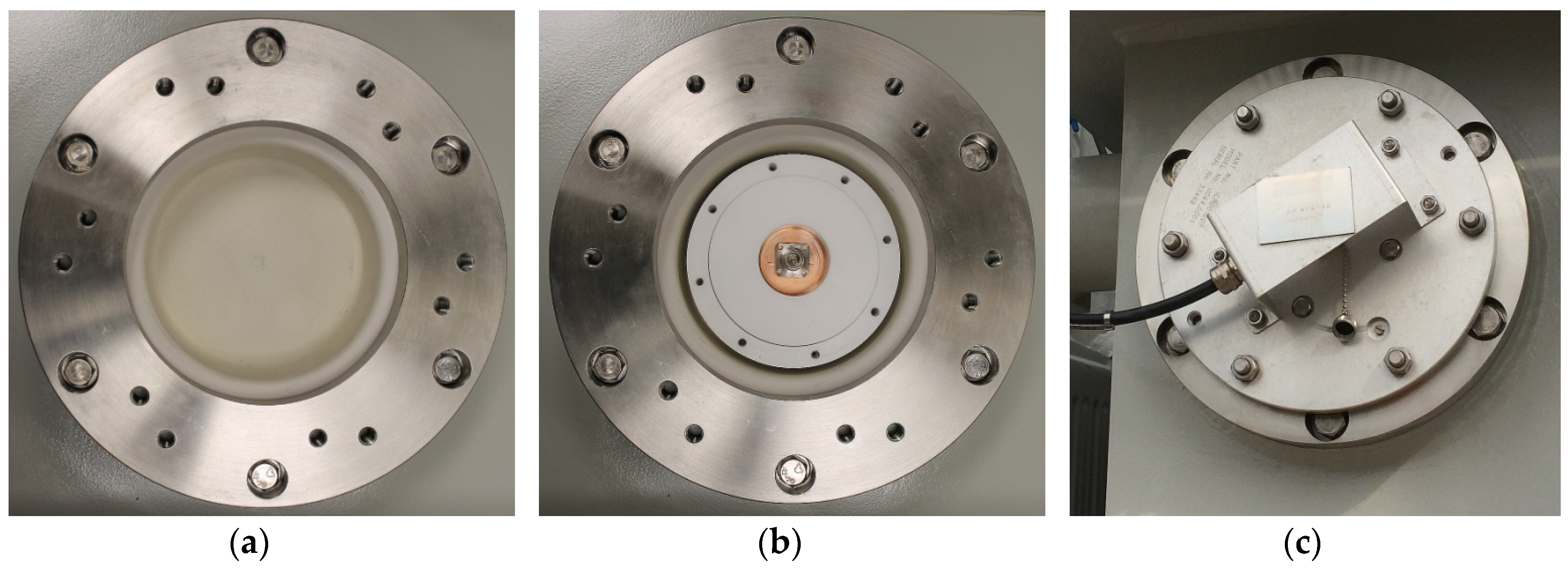
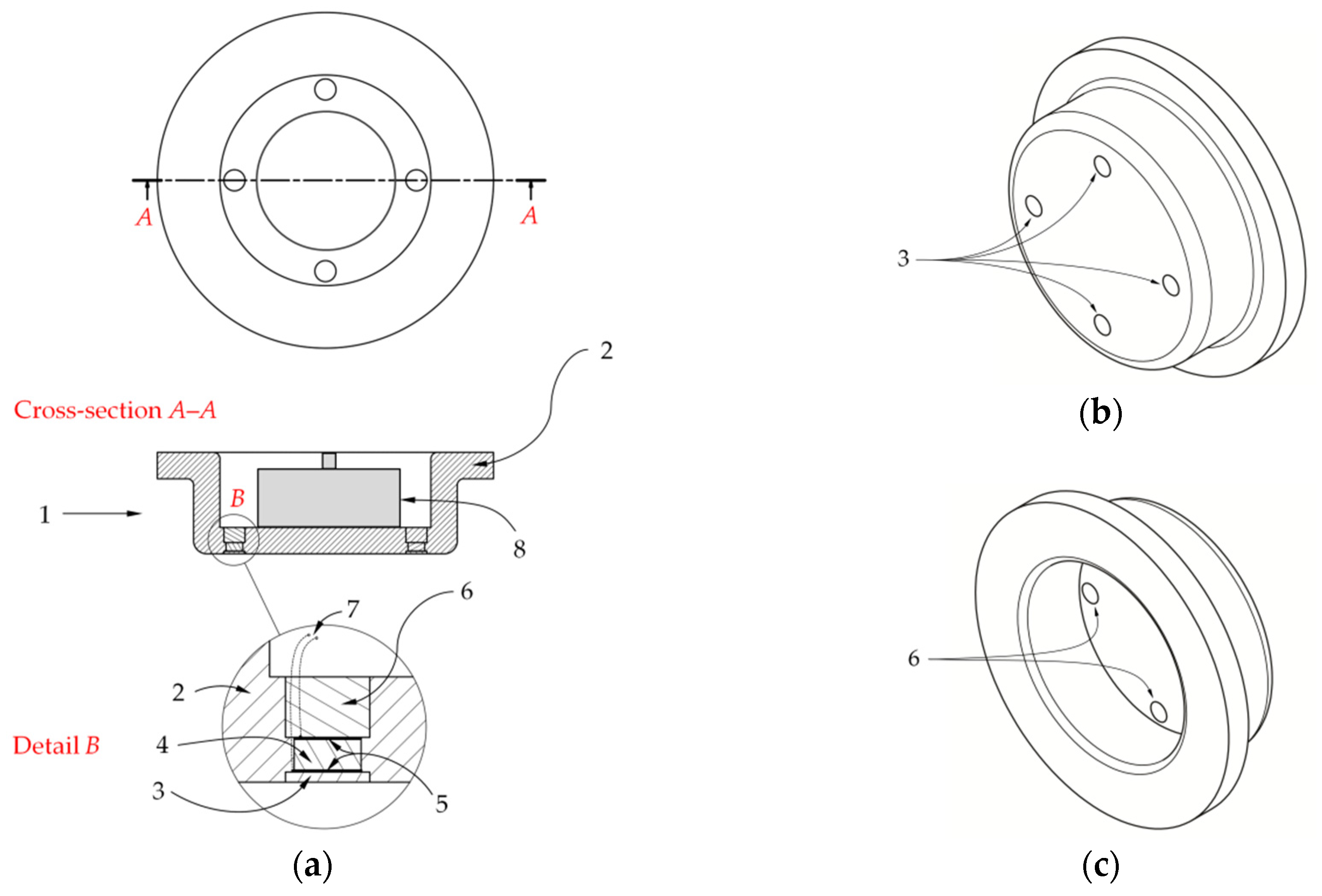
4. Fabrication of a Prototype Active Dielectric Window

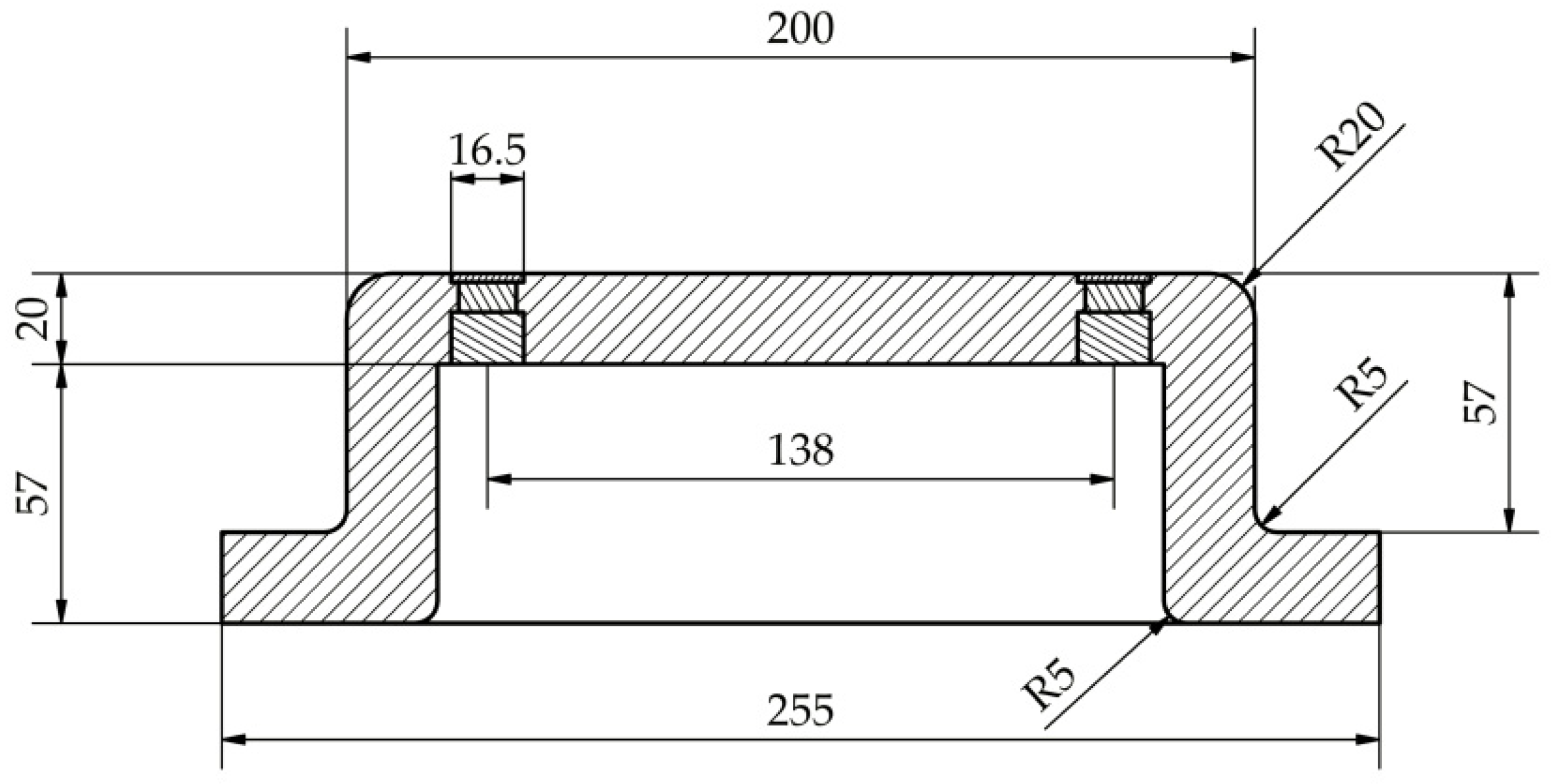
4.1. Dielectric Window

The dielectric window was made using extrusion technology with high-strength aluminous porcelain. The parameters are listed in Table 4. This material was chosen according to its numerous advantages, among which the most important were high-temperature resistance, high electrical resistivity, very good chemical resistance to mineral oil, high hardness, easy surface treatment, and low cost of fabrication.
In the next stage of the prototype ADW production, four radial holes for piezoelectric transducers were made. The shape of the cross-section and dimensions of the ADW are presented in Figure 9.
Before starting the fabrication of the ultrasonic transducers, the front side of the dielectric window and hole walls were covered with ~1.8–2-mm acoustic insulation layer (Figure 10a). The layer performed the function of an attenuating barrier of both transverse and longitudinal ultrasonic waves as well as transformer tank vibrations, which could excite piezoelectric elements. Polyurethane elastomer was chosen as an attenuating material, because it has very good sound attenuating properties [29,30,31] as well as high mechanical and thermal durability (Table 5). In order to increase the efficiency of sound attenuation during the mixing of the two components (polyol and isocyanate) of polyurethane together, small air bubbles were intentionally added to the mixture (Figure 10b). This way, a porous material with very good sound attenuating properties was obtained [32,33]. The measurement results showed that covering the dielectric window with a 2-mm layer of porous polyurethane elastomer caused attenuation of longitudinal waves by 25.47 dB and transversal waves by 24.98 dB on average.

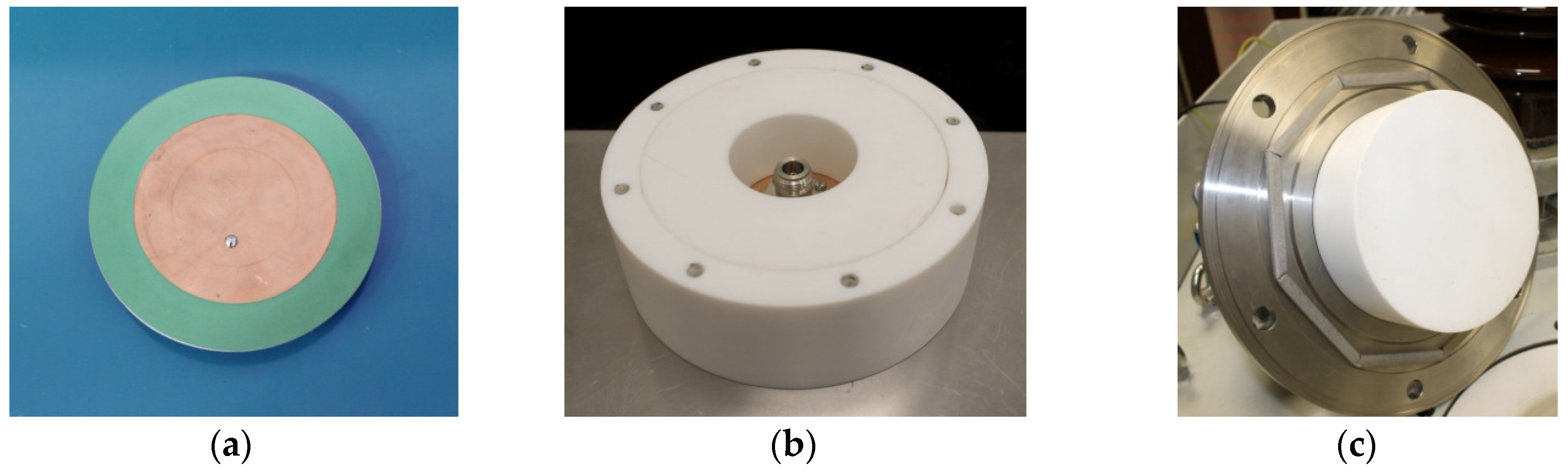
4.2. Ultrasonic Transducers

In the next ADW production stage, the main ultrasonic transducer components were placed in previously drilled holes. These components included piezoelectric ceramics and matching and backing layers. The parameters are listed in Table 3. A technical drawing with the dimensions is presented in Figure 11. The prototype was equipped with four piezoelectric ultrasonic transducers, allowing for, besides online PD monitoring, localization of the position of a PD source by estimating the time difference of arrival between registered UHF and AE signals. As was mentioned before, the ADW may also be made in a simplified version for continuous (online) monitoring of partial discharge intensity. In this configuration, the dielectric window has no acoustic insulation layer and is equipped with only one ultrasonic transducer.
Having fabricated the ultrasonic transducers, their calibration was carried out according to the ASTM E976 standard (the so-called “face-to-face” test) [34,35]. Figure 12 presents a typical, representative frequency response curve, the shape of which largely coincides with characteristics predicted by the KLM model (see Figure 8). According to the adopted project assumptions discussed in Section 3.4, a relatively flat curve in the range between ~120 and ~270 kHz was obtained. The central frequency amounted to 195 kHz, whereas the first resonance frequency totaled 134 kHz, which means that it was 10 kHz lower than the one predicted by the KLM model.

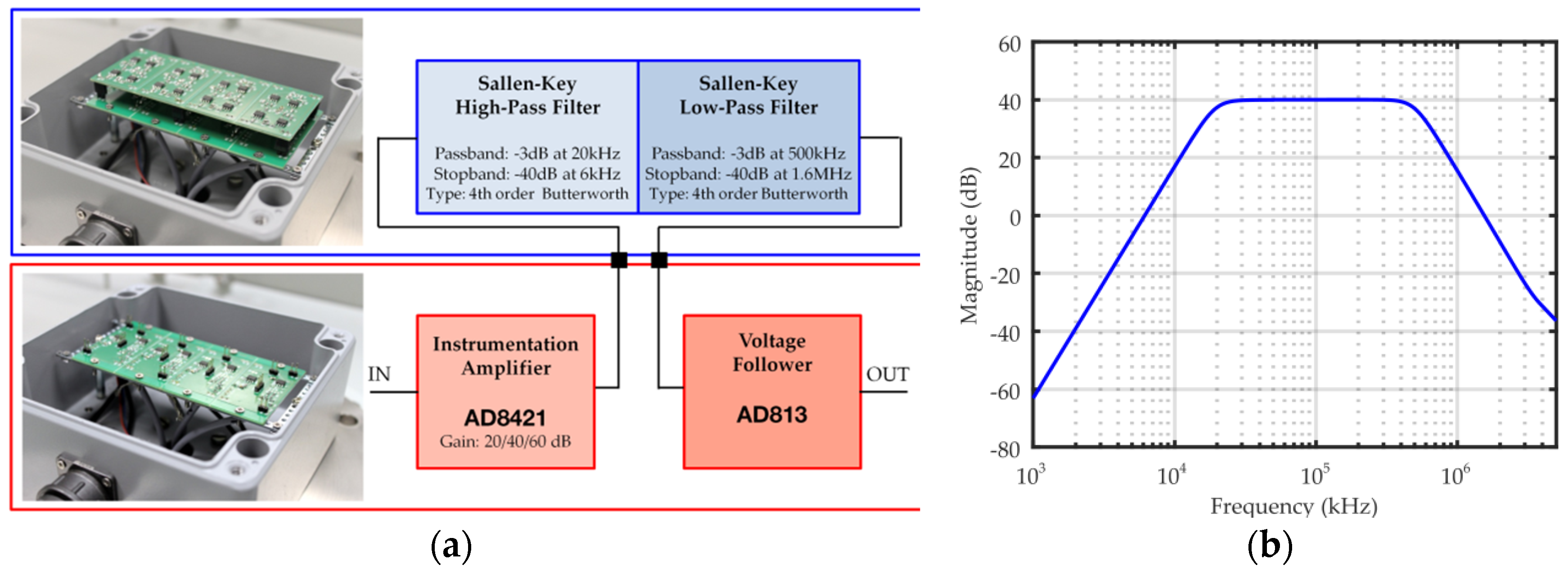
4.3. AE Signal Conditioning Unit
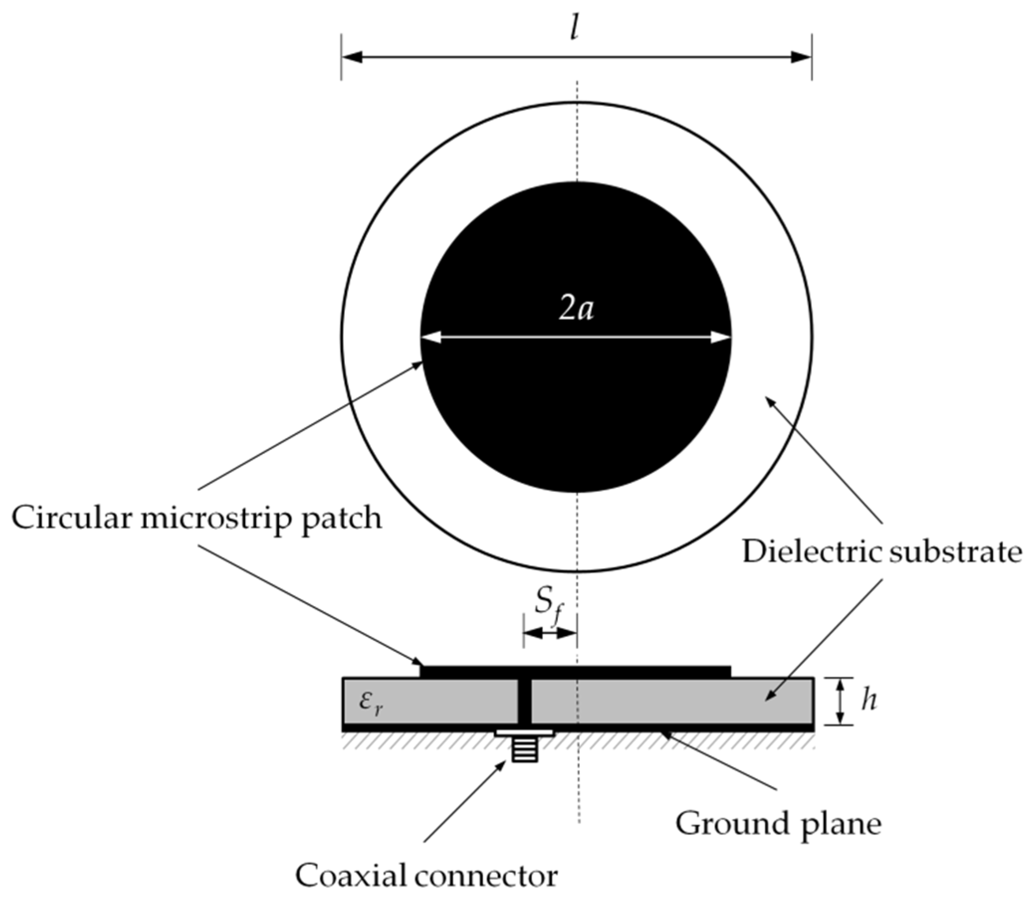
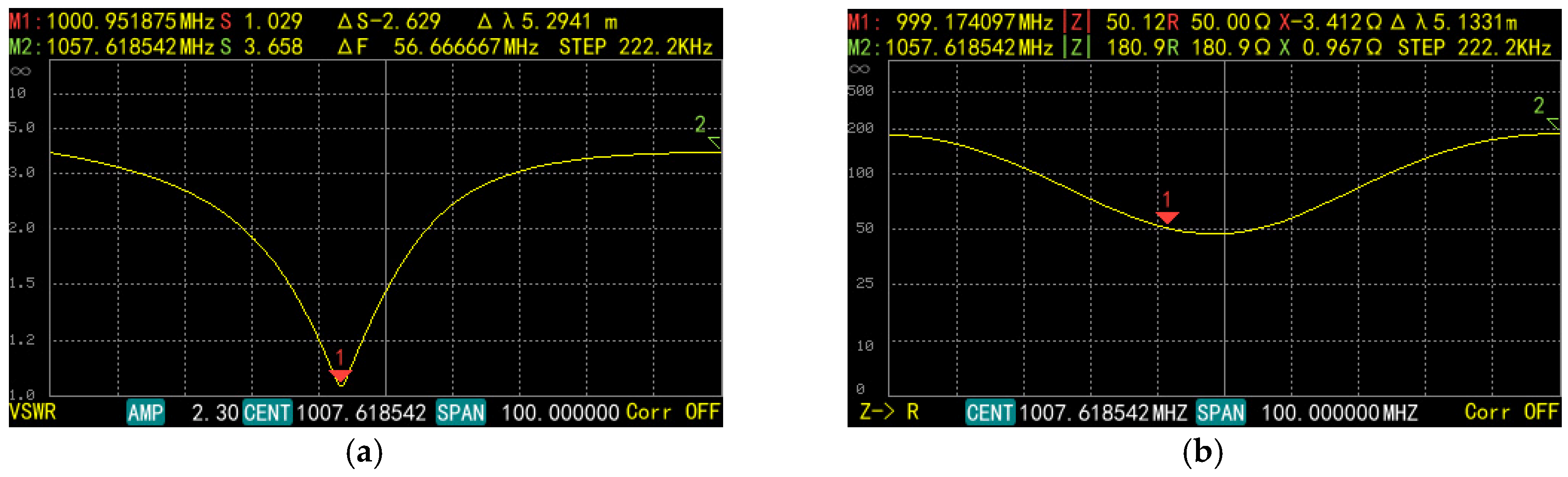
In order to design a low-noise AE signal amplifier, in the first stage of design, the analysis of parameters of the newest available on the market operational and instrumentation amplifiers was carried out, and the most important requirements were defined, such as low voltage noise (<10 nV/√Hz), simultaneously with high gain (G ≥ 100), wide bandwidth (≥500 kHz), low current consumption (<10 mA), and a high common-mode rejection ratio (CMRR > 80 dB). Products of the leading manufacturers currently offering the most advanced electronic components, including Texas Instrument, Analog Devices, Linear Technology, and Maxim Integrated Products, were considered. Eventually, the high-speed instrumentation amplifier AD8421BRZ by Analog Devices (Analog Devices, Norwood, USA) was selected. AD8421BRZ is a low-power (2.3 mA maximum supply current), extremely low-noise (3.2 nV/√Hz maximum input voltage), and ultralow bias current (<500 pA) instrumentation amplifier specially designed for a broad spectrum of signal conditioning and data acquisition applications. Furthermore, AD8421BRZ is one of the most robust instrumentation amplifiers on the market. It features a high electrostatic discharge (ESD) protection rating of 2 kV human body model (HBM), and overvoltage protection (OVP) of 40 V from the opposite supply rail.
At the instrumentation amplifier output, an active bandpass filter (20‒500 kHz) based on Sallen-Key architecture was placed. Both the low- and high-pass sections had the structure of a fourth-order Butterworth filter with unity gain. The ADA4898 (Analog Devices, Norwood, MA, USA) op-amp, belonging to the so-called class of ultralow noise operational amplifiers (noise <1 nV at 100 kHz), was applied as an active element.
At the filter output, the operational amplifier AD813ARZ (Analog Devices, Norwood, MA, USA) performing the function of a voltage follower was applied. Its task was to buffer the output and matching output impedance of the AE signal conditioning unit to the impedance of the coaxial cable (50 Ω). Low current consumption (max 8 mA), low voltage noise (2.9 nV/√Hz), and wide bandwidth amounting to 80 MHz (3 dB, G = 1 V/V) were the most significant parameters recognized during the amplifier selection. Moreover, the output of AD813ARZ could drive capacitive loads (>1000 pF) directly, without parasitic oscillations. Coaxial cables of high quality are characterized by low capacity (approximately 50‒70 pF/m), and therefore for the signal transmission from the amplifier to the signal acquisition unit one may flawlessly use long cables, even more than ten meters in length.
A schematic diagram of the AE signal conditioning unit and its frequency response curve are presented in Figure 13. The measurement results showed that the level of noise at the output of the measuring channel with 40 dB gain and with connected ultrasonic transducer did not exceed 1.6 mVp-p.

4.4. UHF Antenna

While designing the active dielectric window, it was desired to simplify all its components. Therefore, a circular microstrip antenna (CMA) was selected as a radio frequency (RF) detector. This choice was determined by such factors as simple design, low fabrication cost, and ease of assembly in a dielectric window. This antenna type (also called a disk sensor) is commonly applied in online PD monitoring systems for GIS/GIL [17,20,21,36,37]. The limitation of a circular microstrip antenna is relatively low gain and a narrow bandwidth. Therefore, if a first priority is obtaining the highest possible PD detection sensitivity, a CMA may be replaced by one with modern, broadband construction, e.g., a fractal antenna [38,39] or a modified planar inverted-F antenna (PIFA) [40].
A schematic diagram of a circular microstrip antenna fabricated for the prototype ADW is presented in Figure 14.
The fabrication of the antenna FR-4 laminate was of height h = 2.45 mm and relative permittivity εr = 4.4. The diameter of the ground plane amounted to l = 120 mm. The antenna was designed in such a way so that the resonant frequency fr(110) for the dominant TMz110 mode would be equal to 1000 MHz. The radius a = 41.04 mm for the circular patch was calculated using Equation (27):
a = F { 1 + 2 h π ε r F [ ln ( π F 2 h ) + 1.7726 ] } 1 / 2
where
F = 8.791 × 10 9 f r ε r
The antenna was fabricated with PCB technology and equipped with a type N connector. The housing was specially designed and manufactured from polytetrafluoroethylene (PTFE). It performs the following tasks: It protects the antenna from accidental damage and corrosion, adequately positions the antenna in the dielectric window, and ensures durable mechanical connection of the antenna with the inspection hatch cover. Figure 15 presents a picture of the antenna and its housing.
Having mounted the antenna in the dielectric window, the measurements of the voltage standing wave ratio (VSWR) and input impedance, which allowed confirmation of the proper fabrication of the detector, were carried out. According to the measurement results, the measured resonant frequency fr(110) for the dominant TMz110 mode (Figure 16a) was equal to ~1 GHz (exactly 1000.95 MHz). The best impedance matching (very close to 50 Ω) was obtained for the feed point offset Sf = 14.8 mm (Figure 16b).

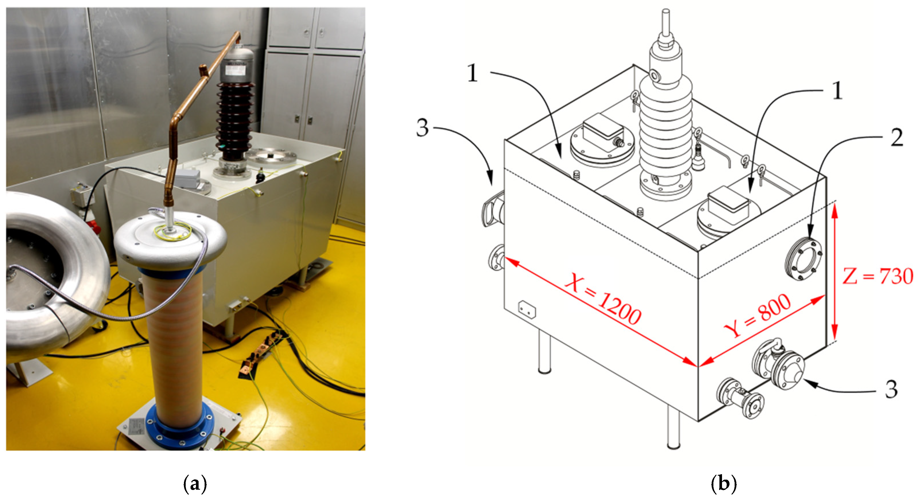
5. Laboratory Tests of the Prototype Active Dielectric Window

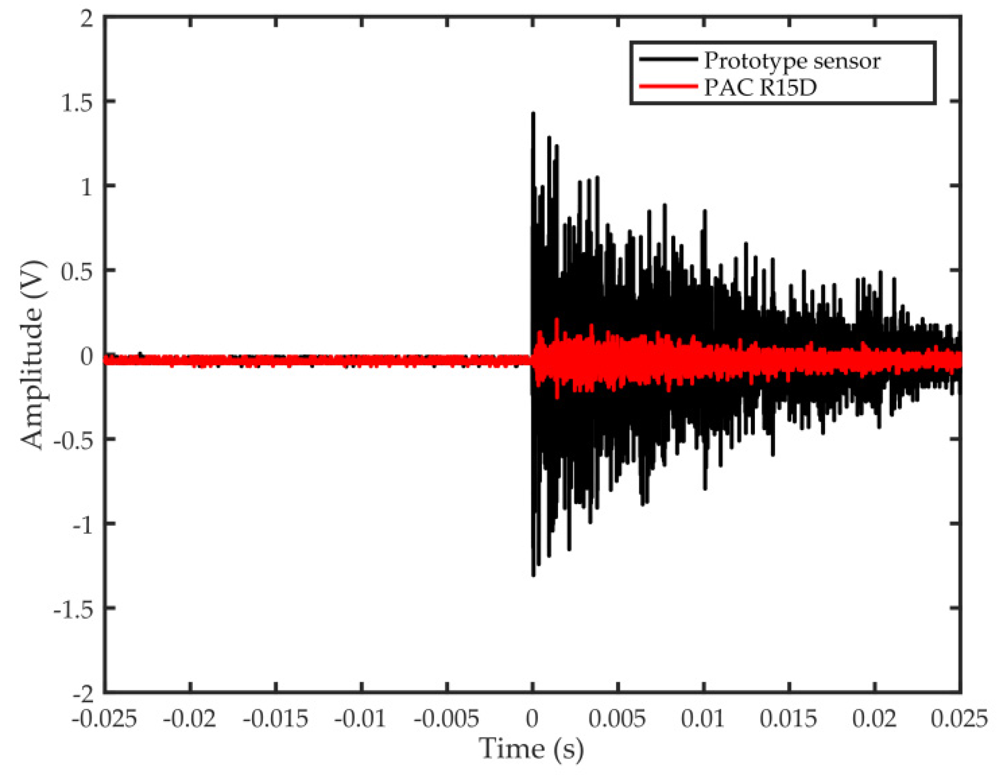
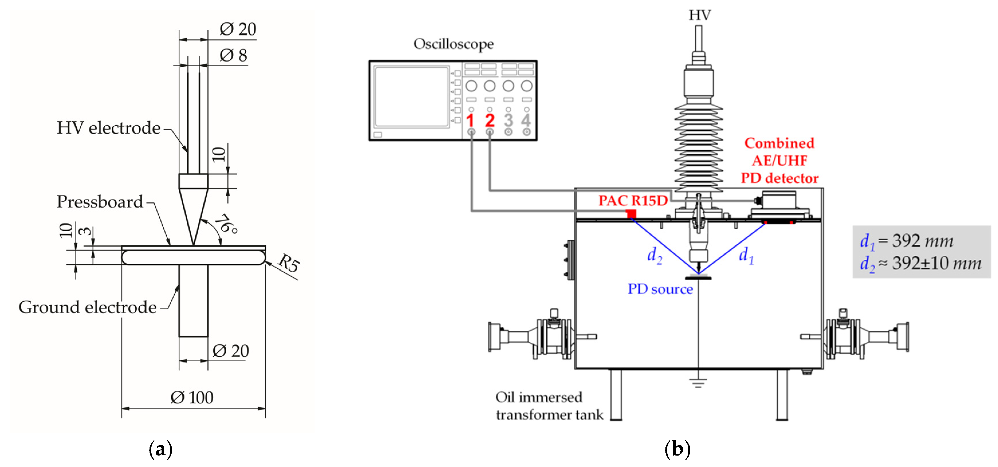
5.1. Sensitivity of Detection of AE Waves Generated by PD

An evaluation of the PD detection sensitivity in the ultrasonic range was carried out in a shielded high-voltage laboratory. The oil-filled model of a transformer tank with dimensions 1200 × 800 × 750 mm was used for the investigation (Figure 17a). The modular structure of the tank top cover enabled easy tank configuration adjustment to the selected measurement scenario. The tank may be equipped with maximally five UHF antennas: Two on the top cover, one on the side wall, and two in the oil drain valves (Figure 17b). If necessary, the inspection hatch with a welded flange may be replaced with an ordinary cover (without a hole).
An electrode system (Figure 18a), in which the creeping discharges were generated on a pressboard sample with a diameter of 100 mm and a height of 3 mm, was placed in the oil-filled transformer tank (Figure 18b). These types of discharges were selected due to the fact that together with turn-to-turn discharges, they are the most dangerous defects that typically result in catastrophic failures at normal operating conditions [41,42,43,44,45].
In order to evaluate the PD detection sensitivity, the AE pulses generated by creeping discharges were registered simultaneously with one of the transducers of the prototype ADW and the reference contact piezoelectric sensor type PAC R15D with 40 dB preamplifier type PAC 2/4/6. Both investigated and referenced ultrasonic transducers were placed 392 mm from the source of discharges (Figure 18a). During the experiment, the level and intensity of PDs were monitored according to the IEC 60270 guidelines using a standard wide-band electrical detector type Doble PD-Smart (Doble Engineering Co, Boston, MA, USA). The inception voltage of creeping discharges amounted to Ui = 19.6 kV. The AE pulse registration was performed with a voltage of 21.3 kV, at which repeated PD pulses with an average value of apparent charge qavg = 356 pC (qmax = 2017 pC) were generated.
The results of the test confirmed, as predicted by the KLM model, a few times higher sensitivity of the ultrasonic transducer optimized for work in transformer oil compared to the popular contact transducer mounted on the transformer tank. A comparative analysis of 250 pairs of AE waveforms showed that the amplitude of the signals registered by the ultrasonic transducer of the ADW was 5.8 times higher on average than that registered by the reference contact transducer PAC R15D. The comparison of the exemplary time waveforms is presented in Figure 19.

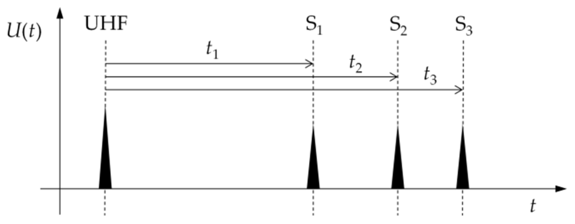
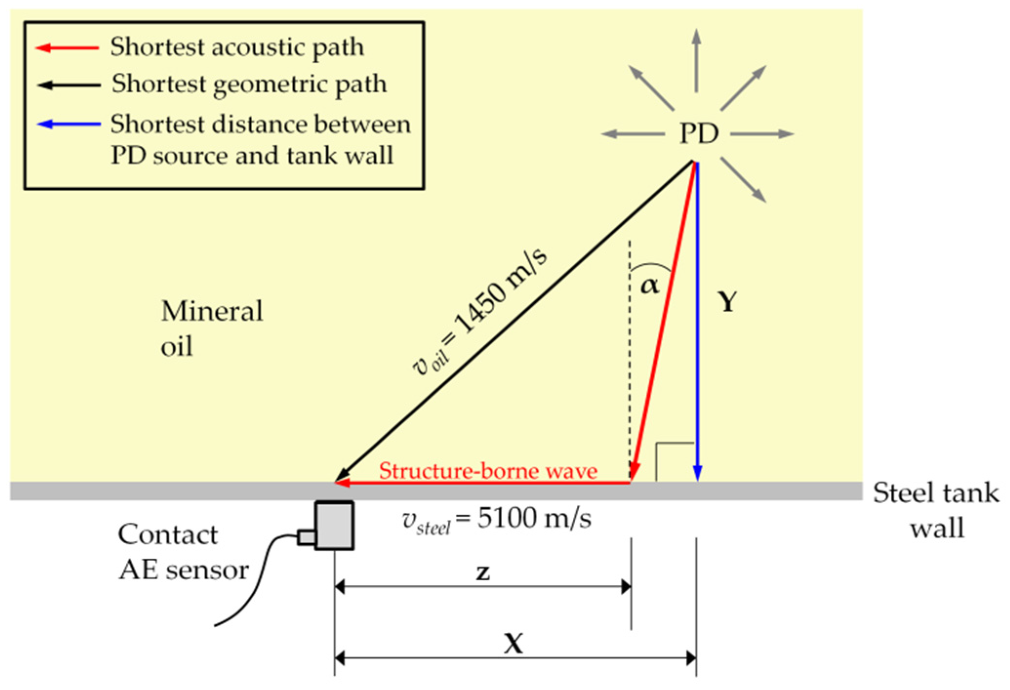
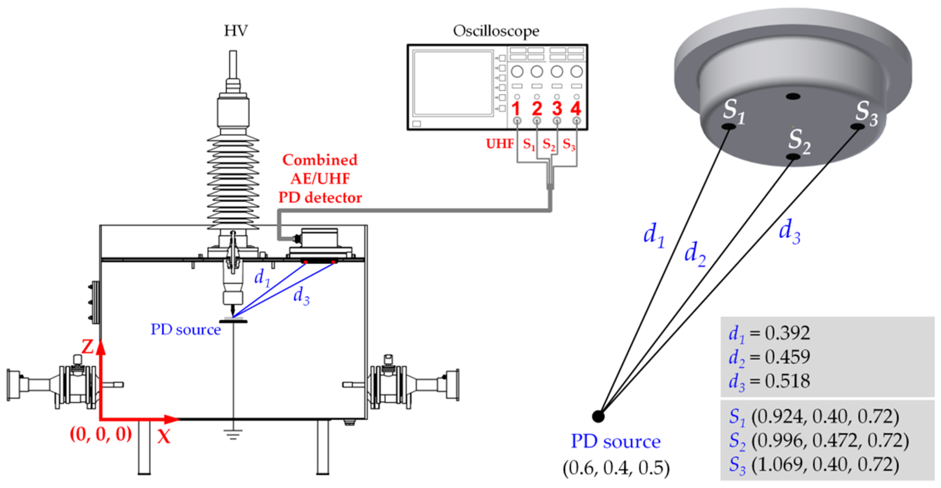
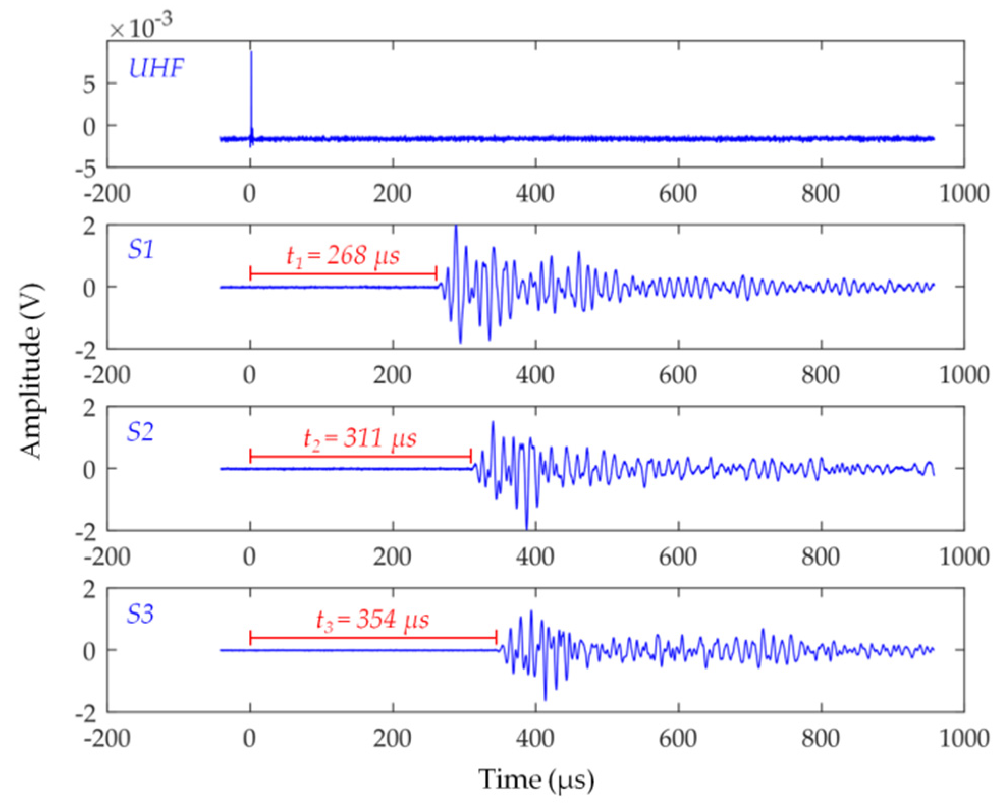
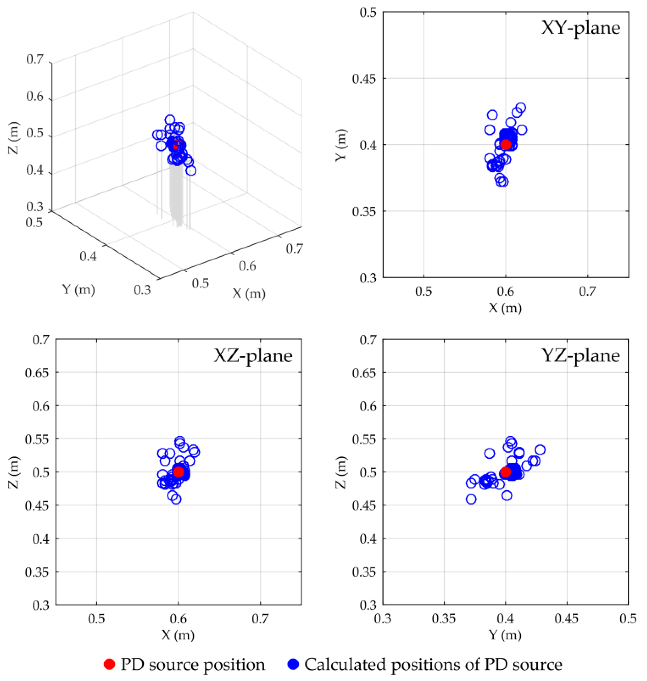
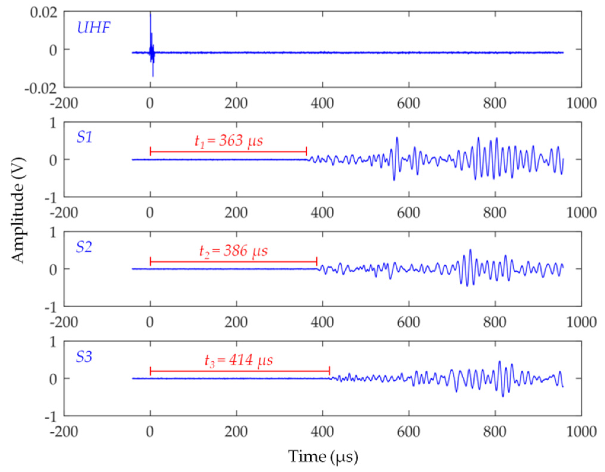
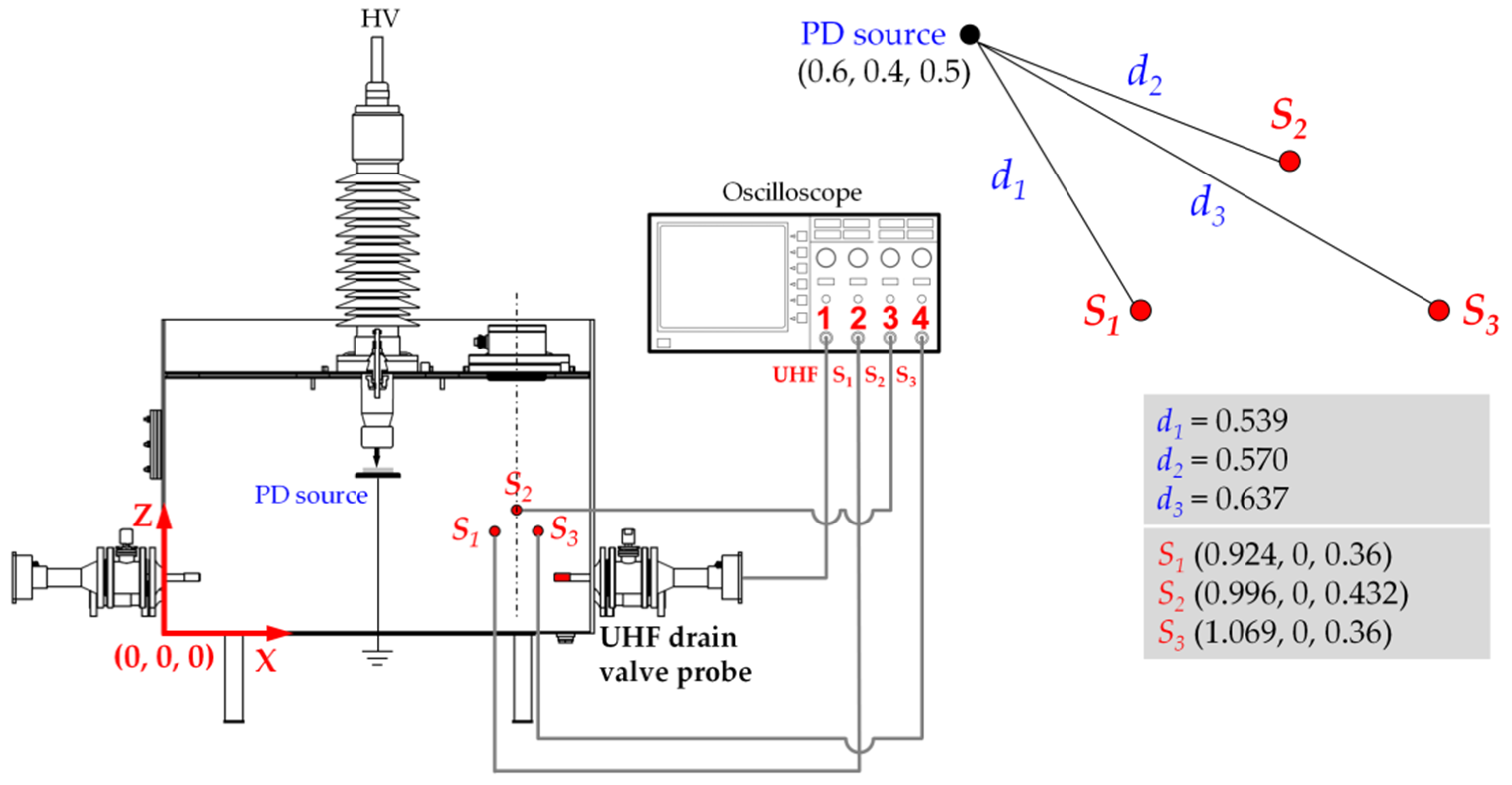
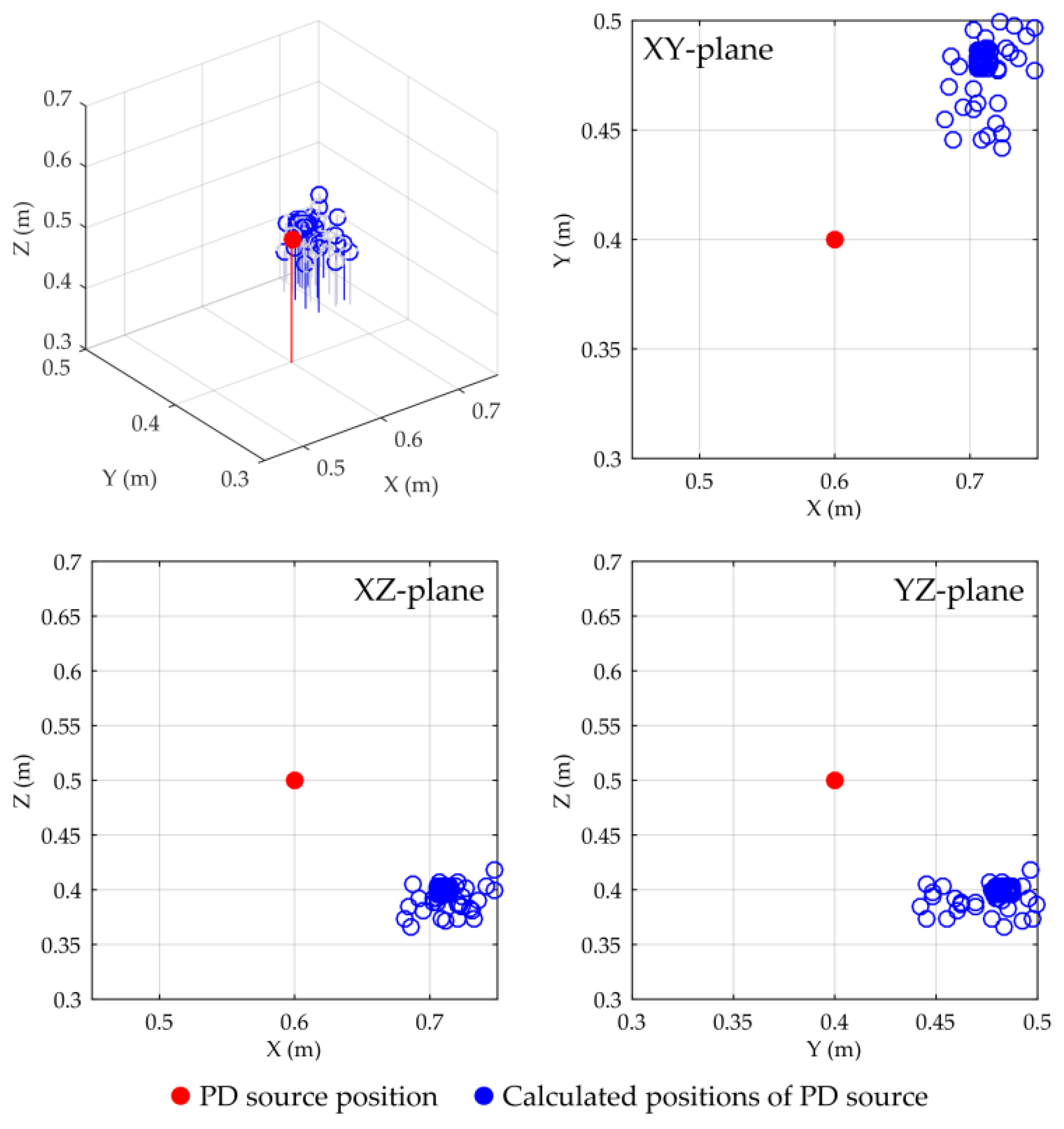
5.2. Test of the PD Source Location Using the Active Dielectric Window and TDOA technique

Location of the PD sources in power transformers is usually carried out using the time difference of arrival technique [16,46] or the standard auscultatory technique (SAT) [47]. In addition, research on the application of the direction of arrival (DOA) technique and sensor arrays has been carried out for several years [48,49,50,51,52].
The measurement procedure of TDOA requires using at least four ultrasonic transducers (so-called “all-acoustic measurements”) or replacing one of the ultrasonic transducers with the UHF antenna (so-called “mixed acoustic-electromagnetic measurements”). In this second approach, time differences in acoustic wave arrival to particular AE sensors relative to electromagnetic pulse registered by the UHF antenna are estimated (Figure 20).
Coordinates (x, y, z) of the PD source are calculated by solving the system of equations below:
( x x S 1 ) 2 + ( y y S 1 ) 2 + ( z z S 1 ) 2 = ( v o i l t 1 ) 2 ( x x S 2 ) 2 + ( y y S 2 ) 2 + ( z z S 2 ) 2 = ( v o π i l t 2 ) 2 , ( x x S 3 ) 2 + ( y y S 3 ) 2 + ( z z S 3 ) 2 = ( v o i l t 3 ) 2
where x, y, z are unknown PD source coordinates in space; xS1...3, yS1...3, yS1...3 are Cartesian coordinates of the AE sensors S1...S3; t1, t2, t3 are measured absolute arrival times; and voil is the propagation velocity of acoustic waves in transformer oil. The above nonlinear system of equations can be solved with one of the direct (non-iterative) solver algorithms [53,54] or with a least square iterative algorithm, the efficiency of which strongly depends on the initial values selected by the user [16].
The main reason for incorrect estimation of the coordinates of the PD source results from the assumption that the AE wave arrives at the transducer along the shortest geometric path (direct path in oil) [2,55]. This assumption is true only in the case when the transducer is in front of a defect. In practice, to the transducer first arrives the wave propagating along the shortest acoustic path (fastest path) (Figure 21) [56]. This is due to the different propagation velocities, which were, approximately, voil = 1450 m/s in oil and vsteel = 5100 m/s in steel, at 30 °C.
The propagation time for the direct path is
t = X 2 + Y 2 v o i l
and for the fastest path is
t = Y v o i l cos α + X Y tan α v s t e e l
where α is the critical incidence angle
α = sin 1 ( v o i l v s t e e l )
In the case of the prototype ADW, due to the application of an acoustic insulation layer and a remaining oil gap between the dielectric window and the tank, the possibility of structure-borne wave registration was reduced (Figure 22).
Laboratory research experiments that allowed pre-evaluation of the effectiveness of the location of PD sources using the ADW were carried out in the measurement set-up, the schematic diagram of which is presented in Figure 23. During the investigation, the creeping PDs were generated at the same electrode system as discussed in Section 5.1. The edge of the HV electrode (PD source) was located at the point with coordinates (0.6, 0.4, 0.5). AE signals were registered using three ultrasonic transducers of the active dielectric window with coordinates S1(0.924, 0.4, 0.72), S2(0.996, 0.472, 0.72), and S3(1.069, 0.4, 0.72). Time differences of arrival t1, t2, t3 were estimated between the onset of the UHF pulse registered with the circular microstrip antenna and onsets of the AE pulses registered by ultrasonic transducers S1, S2, and S3, respectively. In Figure 24, exemplary time waveforms with marked time differences of arrival of the AE signal to ultrasonic transducers are shown.
Figure 25 presents graphically the obtained results of the PD location, whereas the results of the statistical analysis are shown in Table 6.
The obtained results confirmed the possibility of efficient use of the ADW for the location of PD sources. The average location error did not exceed 1.5 cm (3.0%). For comparison, the standard location, i.e., with a UHF drain valve probe, and three contact piezoelectric sensors of type PAC R15D with coordinates S1(0.924, 0, 0.36), S2(0.996, 0, 0.432), and S3(1.069, 0, 0.36) were performed. Due to that, the location of the contact transducers on the x axis was identical to the transducers in the active dielectric window. A detailed schematic diagram of the measurement set-up configuration is presented in Figure 26. In turn, Figure 27 shows exemplary PD pulses with marked time differences of arrival of the AE signal to contact piezoelectric sensors.
The obtained results of the PD location are presented in Table 7 and Figure 28. As one may notice, location with the contact transducers was fraught with much higher error. The highest average (20.8%) and maximal (27%) error were observed for the coordinate Z (in the case of the ADW, it was 3% and 9.2%, respectively). Such a large location error was due to the fact that the contact transducers were located at a high angle to the PD source (> 50°), and therefore they first registered the ultrasonic wave propagating along the shortest acoustic path, whereas approximately its half went to the steel transformer tank. In turn, AE sensors in the ADW, which worked directly in oil, first registered (according to the TDOA method assumptions) the wave propagating along the shortest path in oil (direct path). It should be emphasized that for very small angles, i.e., when the contact transducers were located almost opposite to the PD source, location errors were small, comparable to ADW.

6. Conclusions

This paper presents a new concept of a combined AE/UHF partial discharge detector produced in the form of a dielectric window and designed for assembly in the inspection hatch of a transformer tank. The proposed PD detector, named an active dielectric window, is characterized by a simple design and low fabrication cost. The main innovation of the proposed solution lies in the fact that ultrasonic transducers were built into the dielectric window and optimized for operation in mineral oil. For that reason, the matching layer of ultrasonic transducers was made of specially tailored epoxy/alumina composite with the acoustic impedance equal to the geometric mean of the impedances of transformer oil and piezoelectric ceramics. Such construction facilitated the transfer of the acoustic energy from the liquid medium to the piezoelectric crystal. In effect, it allowed for obtaining a high sensitivity of detection of the AE pulses generated by partial discharges.
Preliminary laboratory tests showed that the amplitude of creeping discharges registered by the ADW was 5.8 higher on average than the amplitude of pulses registered by general purpose contact AE sensors type PAC R15D. The test of the possibility of ADW applications for PD source location using the TDOA technique was similarly positive. Time delays in the acoustic signal arrival to the ultrasonic transducers were measured relative to the UHF signal registered using a circular microstrip antenna placed in the dielectric window. The ADW was designed in a way to maximally limit the possibility of exciting the ultrasonic transducers by the structure-borne waves propagating in a transformer tank wall. This goal was achieved due to the oil gap between the dielectric window and flange, the rubber gasket with sound-attenuating properties, and, most of all, the covering of the window surface with polyurethane acoustic insulation layer.
The results of the laboratory test showed that the average error of the PD location using an ADW amounted to only 3%. For comparison, the measurement with a standard AE system with contact transducers was fraught with an error of over 20%.
Currently, the research, whose aim is to evaluate ADW usefulness in online PD monitoring, is being carried out. In September 2018, two units of ADW were on a pilot basis installed on a power transformer 110 kV/16 kV working in the brown coal mine “Belchatow”. At the same time, research work is being carried out aimed at (1) developing a dielectric window with ultrasound transducers with a lower resonant frequency (approximately 60 kHz (this should guarantee higher sensitivity of detection of high-energy partial discharges)), (2) the construction of a dielectric window using materials with better sound-dampening properties (e.g., porous ceramics or nanoparticle-reinforced polymer composites), and (3) improving the acoustic separation between the piezoelectric element and the dielectric window.

Funding

This work was supported by the Polish National Centre for Research and Development, within the Applied Research Programme, grant No. PBS3/A4/12/2015.

Conflicts of Interest

The author declares no conflicts of interest.

References

  1. Sikorski, W.; Ziomek, W. Detection, Recognition and Location of Partial Discharge Sources Using Acoustic Emission Method. In Acoustic Emission; Sikorski, W., Ed.; IntechOpen: Rijeka, Croatia, 2012; pp. 49–74. ISBN 978-953-51-0056-0. [Google Scholar]
  2. IEEE Guide for the Detection and Location of Acoustic Emissions from Partial Discharges in Oil-Immersed Power Transformers and Reactors. In IEEE Std C57.127-2007 (Revision of IEEE Std C57.127-2000); IEEE: Piscataway, NJ, USA, 2007. [CrossRef]
  3. Lundgaard, L.E. Partial discharge. XIII. Acoustic partial discharge detection-fundamental considerations. IEEE Electr. Insul. Mag. 1992, 8, 25–31. [Google Scholar] [CrossRef]
  4. Bengtsson, T.; Leijon, M.; Ming, L. Acoustic Frequencies Emitted by Partial Discharges in Oil. In Proceedings of the 8th International Symposium on High Voltage Engineering, Yokohama, Japan, 21–23 July 1993; pp. 113–116. [Google Scholar]
  5. Bengtsson, T.; Jönsson, B. Transformer PD diagnosis using acoustic emission technique. In Proceedings of the 10th International Symposium on High Voltage Engineering, Montréal, QC, Canada, 25–29 August 1997; pp. 73–79. [Google Scholar]
  6. Antony, D.; Punekar, G.S. Improvements in AEPD location identification by removing outliers and post processing. In Proceedings of the International Conference on Condition Assessment Techniques in Electrical Systems (CATCON), Bangalore, India, 10–12 December 2015; pp. 66–69. [Google Scholar] [CrossRef]
  7. Chai, M.L.; Thayoob, Y.H.M.; Ghosh, P.S.; Sha’ameri, A.Z.; Talib, M.A. Identification of Different Types of Partial Discharge Sources from Acoustic Emission Signals in the Time-Frequency Representation. In Proceedings of the International Power and Energy Conference, Putra Jaya, Malaysia, 28–29 November 2006; pp. 581–586. [Google Scholar] [CrossRef]
  8. Choi, S.-Y.; Park, D.-W.; Kim, I.-K.; Park, C.-Y.; Kil, G.-S. Analysis of acoustic signals generated by partial discharges in insulation oil. In Proceedings of the 2008 International Conference on Condition Monitoring and Diagnosis, Beijing, China, 21–24 April 2008; pp. 525–528. [Google Scholar] [CrossRef]
  9. Boya, C.; Ruiz-Llata, M.; Posada, J.; Garcia-Souto, J.A. Identification of multiple partial discharge sources using acoustic emission technique and blind source separation. IEEE Trans. Dielectr. Electr. Insul. 2015, 22, 1663–1673. [Google Scholar] [CrossRef]
  10. Hoskins, P.R.; Martin, K.; Thrush, A. Diagnostic Ultrasound: Physics and Equipment; Cambridge University Press: Cambridge, UK, 2010. [Google Scholar]
  11. IEC-62478. High-Voltage Test Techniques—Measurement of Partial Discharges by Electromagnetic and Acoustic Methods; International Electrotechnical Commission (IEC): Geneva, Switzerland, 2016. [Google Scholar]
  12. Walczak, K.; Sikorski, W.; Siodla, K.; Andrzejewski, M.; Gil, W. Online condition monitoring and expert system for power transformers. In Proceedings of the 3rd Advanced Research Workshop on Transformers, Santiago de Compostella, Spain, 3–10 October 2010; pp. 433–438. [Google Scholar]
  13. Sikorski, W.; Walczak, K.; Moranda, H.; Gil, W.; Andrzejewski, M. Partial discharge on-line monitoring system based on acoustic emission method—Operational experiences. Prz. Elektrotech. 2012, 88, 117–121. [Google Scholar]
  14. Albarracín, R.; Ardila-Rey, J.A.; Mas’ud, A.A. On the Use of Monopole Antennas for Determining the Effect of the Enclosure of a Power Transformer Tank in Partial Discharges Electromagnetic Propagation. Sensors 2016, 16, 148. [Google Scholar] [CrossRef] [PubMed]
  15. Fofana, I.; Hadjadj, Y. Electrical-Based Diagnostic Techniques for Assessing Insulation Condition in Aged Transformers. Energies 2016, 9, 679. [Google Scholar] [CrossRef]
  16. Markalous, S.; Tenbohlen, S.; Feser, K. Detection and location of partial discharges in power transformers using acoustic and electromagnetic signals. IEEE Trans. Dielectr. Electr. Insul. 2008, 15, 1576–1583. [Google Scholar] [CrossRef]
  17. Unsworth, J. Partial Discharge Monitoring System for Transformers. U.S. Patent Grant No. US6774639B1, 2 September 1999. [Google Scholar]
  18. Unsworth, J.; Kurusingal, J.; James, R.E. On-line partial discharge monitor for high voltage power transformers. In Proceedings of the 4th International Conference on Properties and Applications of Dielectric Materials (ICPADM), Brisbane, Australia, 3–8 July 1994; Volume 2, pp. 729–732. [Google Scholar] [CrossRef]
  19. Siegel, M.; Beltle, M.; Tenbohlen, S.; Coenen, S. Application of UHF sensors for PD measurement at power transformers. IEEE Trans. Dielectr. Electr. Insul. 2017, 24, 331–339. [Google Scholar] [CrossRef]
  20. Judd, M.D.; Farish, J.S.; Pearson, J.S.; Hampton, B.F. Dielectric windows for UHF partial discharge detection. IEEE Trans. Dielectr. Electr. Insul. 2001, 8, 953–958. [Google Scholar] [CrossRef]
  21. Judd, M.D.; Farish, J.S.; Hampton, B.F. Broadband couplers for UHF detection of partial discharge in gas-insulated substations. IEE Proc. Sci. Meas. Technol. 1995, 142, 237–243. [Google Scholar] [CrossRef]
  22. CIGRE. Experiences in Service with New Insulating Liquids; CIGRE Brochure N° 436; CIGRE: Paris, France, 2010. [Google Scholar]
  23. Nadolny, Z.; Dombek, G. Electro-Insulating Nanofluids Based on Synthetic Ester and TiO2 or C60 Nanoparticles in Power Transformer. Energies 2018, 11, 1953. [Google Scholar] [CrossRef]
  24. Li, P.; Dai, K.; Zhang, T.; Jin, Y.; Liu, Y.; Liao, Y. An Accurate and Efficient Time Delay Estimation Method of Ultra-High Frequency Signals for Partial Discharge Localization in Substations. Sensors 2018, 18, 3439. [Google Scholar] [CrossRef] [PubMed]
  25. Mason, W.P. Electromechanical Transducers and Wave Filters, 2nd ed.; Van Nostrand: Princeton, NJ, USA, 1948; ISBN 9780442051648. [Google Scholar]
  26. Redwood, M. Transient performance of a piezoelectric transducer. J. Acoust. Soc. Am. 1961, 33, 527–536. [Google Scholar] [CrossRef]
  27. Krimholtz, R.; Leedom, D.A.; Matthaei, G.L. New equivalent circuits for elementary piezoelectric transducers. Electron. Lett. 1970, 6, 398–399. [Google Scholar] [CrossRef]
  28. Devaney, A.J.; Levine, H. Effective elastic parameters of random composites. Appl. Phys. Lett. 1980, 37, 377–379. [Google Scholar] [CrossRef]
  29. Imai, Y.; Asano, T. Studies of acoustical absorption of flexible polyurethane foam. J. Appl. Polym. Sci. 1982, 27, 183–195. [Google Scholar] [CrossRef]
  30. Herrington, R.; Broos, R.; Knaub, P. Flexible Polyurethane Foams. In Handbook of Polymeric Foams and Foam Technology, 2nd ed.; Klempner, D., Sendijarevic, V., Eds.; Hanser Publishers: Munich, Germany, 2004; pp. 55–119, ISBN-13: 978-1569903360. [Google Scholar]
  31. Andersson, A.; Lundmark, S.; Magnusson, A.; Maurer, F.H.J. Vibration and acoustic damping of flexible polyurethane foams modified with a hyperbranched polymer. J. Cell. Plast. 2010, 46, 73–93. [Google Scholar] [CrossRef]
  32. Doutres, O.; Atalla, N.; Dong, K. Effect of the microstructure closed pore content on the acoustic behavior of polyurethane foams. J. Appl. Phys. 2011, 110, 239–246. [Google Scholar] [CrossRef]
  33. Hong, Z.; Bo, L.; Guangsu, H. Sound absorption behavior of multiporous hollow polymer micro-spheres. Mater. Lett. 2006, 60, 3451–3456. [Google Scholar] [CrossRef]
  34. ASTM E976-10 Standard Guide for Determining the Reproducibility of Acoustic Emission Sensor Response; ASTM International: West Conshohocken, PA, USA, 2016; 7p.
  35. Ono, K. Calibration Methods of Acoustic Emission Sensors. Materials 2016, 9, 508. [Google Scholar] [CrossRef]
  36. Hoshino, T.; Maruyama, S.; Ohtsuka, S.; Hikita, M.; Wada, J.; Okabe, S. Sensitivity comparison of disc- and loop-type sensors using the UHF method to detect partial discharges in GIS. IEEE Trans. Dielectr. Electr. Insul. 2012, 19, 910–916. [Google Scholar] [CrossRef]
  37. Pearson, J.S.; Farish, O.; Hampton, B.F.; Judd, M.D.; Templeton, D.; Pryor, B.W.; Welch, I.M. Partial discharge diagnostics for gas insulated substations. IEEE Trans. Dielectr. Electr. Insul. 1995, 2, 893–905. [Google Scholar] [CrossRef]
  38. Sikorski, W.; Szymczak, C.; Siodla, K.; Polak, F. Hilbert curve fractal antenna for detection and on-line monitoring of partial discharges in power transformers. Eksploat. I Niezawodn. Maint. Reliab. 2018, 20, 343–351. [Google Scholar] [CrossRef]
  39. Li, J.; Li, X.; Du, L.; Cao, M.; Qian, G. An Intelligent Sensor for the Ultra-High-Frequency Partial Discharge Online Monitoring of Power Transformers. Energies 2016, 9, 383. [Google Scholar] [CrossRef]
  40. Szymczak, C.; Sikorski, W.; Siodla, K.; Grabia, M. Design of PIFA-type UHF antenna for partial discharge monitoring in power transformer. Prz. Elektrotech. 2018, 94, 138–142. (In Polish) [Google Scholar] [CrossRef]
  41. Sokolov, V.; Berler, Z.; Rashkes, V. Effective methods of assessment of insulation system conditions in power transformers: A view based on practical experience. In Proceedings of the Electrical Insulation Conference and Electrical Manufacturing and Coil Winding Conference (Cat. No.99CH37035), Cincinnati, OH, USA, 28 October 1999; pp. 659–667. [Google Scholar] [CrossRef]
  42. Liao, R.; Hu, E.; Yang, L.; Duan, L. The process of creeping discharge-caused damage on oil/pressboard insulation. Turk. J. Electr. Eng. Comput. Sci. 2016, 24, 1434–1445. [Google Scholar] [CrossRef]
  43. Rozga, P.; Stanek, M.; Pasternak, B. Characteristics of Negative Streamer Development in Ester Liquids and Mineral Oil in a Point-To-Sphere Electrode System with a Pressboard Barrier. Energies 2018, 11, 1088. [Google Scholar] [CrossRef]
  44. Sikorski, W.; Walczak, K.; Przybylek, P. Moisture Migration in an Oil-Paper Insulation System in Relation to Online Partial Discharge Monitoring of Power Transformers. Energies 2016, 9, 1082. [Google Scholar] [CrossRef]
  45. Dombek, G.; Gielniak, J.; Wroblewski, R. Fire safety and electrical properties of mineral oil/synthetic ester mixtures. In Proceedings of the 2017 International Symposium on Electrical Insulating Materials (ISEIM), Toyohashi, Japan, 11–15 September 2017; pp. 227–230. [Google Scholar] [CrossRef]
  46. Sikorski, W.; Walczak, K. Power Transformer Diagnostics Based on Acoustic Emission Method. In Acoustic Emission—Research and Applications; Sikorski, W., Ed.; IntechOpen: Rijeka, Croatia, 2013; pp. 91–116. ISBN 978-953-51-1015-6. [Google Scholar]
  47. Sikorski, W.; Siodla, K.; Moranda, H.; Ziomek, W. Location of partial discharge sources in power transformers based on advanced auscultatory technique. IEEE Trans. Dielectr. Electr. Insul. 2012, 19, 1948–1956. [Google Scholar] [CrossRef]
  48. Luo, Y.F.; Li, Y.M.; Liu, L.C. Simulation of PD location method in oil based on UHF and ultrasonic phased array receiving theory. Trans. China Electrotech. Technol. Soc. 2004, 19, 35–39. [Google Scholar]
  49. Polak, F.; Sikorski, W.; Siodla, K. Location of partial discharges sources using sensor arrays. In Proceedings of the 2014 International Conference on High Voltage Engineering and Application (ICHVE), Poznan, Poland, 8–11 September 2014; pp. 1–4. [Google Scholar] [CrossRef]
  50. Xie, Q.; Cheng, S.; Lü, F.; Li, Y. Location of partial discharge in transformer oil using circular array of ultrasonic sensors. IEEE Trans. Dielectr. Electr. Insul. 2013, 20, 1683–1690. [Google Scholar] [CrossRef]
  51. Gao, S.; Zhang, Y.; Xie, Q.; Kan, Y.; Li, S.; Liu, D.; Lü, F. Research on Partial Discharge Source Localization Based on an Ultrasonic Array and a Step-by-Step Over-Complete Dictionary. Energies 2017, 10, 593. [Google Scholar] [CrossRef]
  52. Yongfen, L.; Xiaohu, X.; Fei, D.; Xiao, T.; Yanming, L. Comparison of DOA Algorithms Applied to Ultrasonic Arrays for PD Location in Oil. IEEE Sens. J. 2015, 15, 2316–2323. [Google Scholar] [CrossRef]
  53. Awange, J.L.; Grafarend, E.W. Algebraic solution of GPS Pseudo-Ranging Equations. GPS Solut. 2002, 5, 20–32. [Google Scholar] [CrossRef]
  54. Krause, L.O. A direct solution to GPS-type navigation equations. IEEE Trans. Aerosp. Electron. Syst. 1987, AES-23, 225–232. [Google Scholar] [CrossRef]
  55. Lundgaard, L.E. Partial discharge. XIV. Acoustic partial discharge detection—Practical application. IEEE Electr. Insul. Mag. 1992, 8, 34–43. [Google Scholar] [CrossRef]
  56. Phung, B.T.; Blackburn, T.R.; Liu, Z. Acoustic measurements of partial discharge signals. J. Electr. Electron. Eng. 2001, 21, 41–47. [Google Scholar]
Figure 1. Schematic diagram of a contact piezoelectric transducer mounted on the surface of a power transformer tank.
Energies 12 00115 g001
Figure 2. Inspection hatch in the power transformer tank: (a) Dielectric window; (b) ultrahigh frequency (UHF) antenna (partial discharge (PD) detector) installed in the dielectric window; (c) inspection hole cover with electronics in the enclosure.
Energies 12 00115 g002
Figure 3. Schematic diagram of the active dielectric window: (a) Top and cross-sectional view; (b) isometric view of the front and (c) the back side of the active dielectric window (ADW). Indications of structural elements: 1 = active dielectric window; 2 = ceramics; 3 = matching layer; 4 = piezoelectric crystal; 5 = electrodes; 6 = backing layer; 7 = electrical leads; 8 = UHF antenna (PD detector).
Energies 12 00115 g003
Figure 4. The method of assembling the active dielectric window in the inspection hole.
Energies 12 00115 g004
Figure 5. General structure of the Krimholtz, Leedom, and Matthaei (KLM) model of the piezoelectric transducer.
Energies 12 00115 g005
Figure 6. Effect of alumina volume fraction on acoustic impedance of a composite material.
Energies 12 00115 g006
Figure 7. Effect of tungsten volume fraction on acoustic impedance of a composite material.
Energies 12 00115 g007
Figure 8. Modeled pulse–echo waveform (black) and frequency spectrum (red) of the transducer with a quarter wavelength matching layer made by an epoxy/alumina composite.
Energies 12 00115 g008
Figure 9. Technical drawing with the dimensions of the prototype active dielectric window.
Energies 12 00115 g009
Figure 10. Active dielectric window with acoustic insulation: (a) Photograph of the front part of the ADW covered with a ~2-mm layer of polyurethane elastomer; (b) microscopic photo of the cross-section of a polyurethane sample with air bubbles (visible here as white areas).
Energies 12 00115 g010
Figure 11. Structural elements of the ultrasonic transducer built into the dielectric window: (a) Technical drawing with the dimensions; (b) photo showing backing layers and electrical leads embedded in the prototype ADW.
Energies 12 00115 g011
Figure 12. Typical acoustic emission (AE) waveform (black) and frequency response (red) registered during an ultrasonic transducer calibration performed according to the ASTM E976 standard.
Energies 12 00115 g012
Figure 13. Four-channel AE signal conditioning unit: (a) Schematic diagram with pictures of the fabricated PCB boards; (b) frequency response curve.
Energies 12 00115 g013
Figure 14. Schematic diagram of a circular microstrip antenna.
Energies 12 00115 g014
Figure 15. Photos of the fabricated circular microstrip UHF antenna for PD detection: (a) Front view; (b) antenna housing; (c) antenna fixed to the inspection hatch cover.
Energies 12 00115 g015
Figure 16. The measured parameters of the fabricated UHF antenna: (a) Voltage standing wave ratio (VSWR); (b) input impedance.
Energies 12 00115 g016
Figure 17. Oil-filled transformer tank: (a) Photograph of the test stand in the shielded high-voltage laboratory; (b) schematic diagram: 1 = inspection hatch with UHF sensors (or plain cover), 2 = inspection hatch with the dielectric window made of poly (methyl methacrylate) (PMMA), 3 = oil drain valve.
Energies 12 00115 g017
Figure 18. (a) Schematic diagram of the measurement system for evaluating the sensitivity of PD detection in the ultrasound range; (b) electrode system for creeping discharges in oil (PD source).
Energies 12 00115 g018
Figure 19. The comparison of the exemplary time waveforms registered by the prototype ultrasonic transducer of the ADW and reference contact piezoelectric transducer type PAC R15D.
Energies 12 00115 g019
Figure 20. Schematic diagram of the absolute acoustic arrival times (t1, t2, t3) to the PD onset (electromagnetic PD trigger signal).
Energies 12 00115 g020
Figure 21. Model of propagation of acoustic waves from the PD source to the contact AE sensor.
Energies 12 00115 g021
Figure 22. Structural solutions (acoustic insulation layer and oil gap) used in the prototype ADW, reducing the possibility of structure-borne wave registration.
Energies 12 00115 g022
Figure 23. The measurement set-up for testing the effectiveness of a partial discharge source location using the prototype ADW.
Energies 12 00115 g023
Figure 24. Typical time waveforms with marked time differences of arrival of the AE signal to ultrasonic transducers.
Energies 12 00115 g024
Figure 25. Graphical presentation of the results of PD source location using the prototype active dielectric window: Pseudo-3D plot and projection of solutions on the XY, XZ, and YZ planes.
Energies 12 00115 g025
Figure 26. The measurement set-up for testing the effectiveness of partial discharge source location using a UHF drain valve probe and three standard contact piezoelectric sensors.
Energies 12 00115 g026
Figure 27. Typical time waveforms with marked time differences of arrival of the AE signal to ultrasonic transducers.
Energies 12 00115 g027
Figure 28. Graphical presentation of the PD source location using a UHF drain valve probe and three piezoelectric contact transducers: Pseudo-3D plot and projection of solutions on the XY, XZ, and YZ planes.
Energies 12 00115 g028
Table 1. Properties of the materials used to design the matching and backing layer of an ultrasonic transducer.
ParameterMaterialSymbolUnit
EpoxyAlumina PowderTungsten Powder
Density1094 a367019250ρkg/m3
Bulk modulus 5.1165310KGPa
Shear modulus1.5124161GGPa
Longitudinal velocity255094875221VLm/s
Shear velocity117458132892VSm/s
Acoustic impedance2.7934.8100.5ZMRayl
Particle sizeN/A10.6‒1Dμm
PurityN/A≥99.9≥99.9 b%
a At 25 °C; b based on trace metals analysis.
Table 2. Properties of the piezoelectric ceramic used.
ParameterSymbolValueUnit
Relative dielectric constant KT1900
Electromechanical coupling coefficients:
Longitudinal coupling coefficientk330.72
Transverse coupling coefficientk310.36
Shear coupling coefficientk150.68
Planar coupling coefficientkp0.63
Thickness coupling factorkt0.49
Piezoelectric charge constants:
Induced strain in direction 3 per unit electric field Energies 12 00115 i001d33400m/V3
Induced strain in direction 1 per unit electric field applied in direction 3d31175m/V3
Induced shear strain about direction 2 per unit electric field applied in direction 1d15590m/V3
Dielectric dissipation factor (dielectric loss) 1tan σ≤2.00%
Frequency constants:
Frequency constant for thickness vibration modeNT2040Hz·m
Frequency constant for planar vibration modeNP1980Hz·m
Frequency constant for longitudinal vibration modeNL1500Hz·m
Curie point 2TC360°C
Densityρ7600kg/m3
1 At 1 kHz, low field; 2 maximum operating temperature = Curie point/2; 3 10−12 C/N.
Table 3. Parameters of piezoelectric transducer structures optimized using the KLM model.
ParameterSymbolValueUnit
Active layer (piezoelectric ceramic):
Thicknessd6.2Mm
Radiusr6.35Mm
AreaA126.61mm2
Acoustic impedanceZ031.0MRayl
Backing layer 1:
Thickness d8.8Mm
Densityρ2546kg/m3
Longitudinal velocityVL1790m/s
Shear velocityVS845m/s
Acoustic impedanceZB4.56MRayl
Bulk modulusK5.74GPa
Shear modulusG1.82GPa
Matching layer 2:
Thickness d5.05Mm
Densityρ2079kg/m3
Longitudinal velocityVL3029m/s
Shear velocityVS1640m/s
Bulk modulusK11.62GPa
Shear modulusG5.59GPa
Acoustic impedanceZM6.3MRayl
1 Epoxy/tungsten composite with 0.08 volume fraction of tungsten; 2 epoxy/alumina composite with 0.3825 volume fraction of alumina.
Table 4. Properties of the high-strength aluminous porcelain used to construct the dielectric window.
ParameterSymbolValueUnit
Apparent (bulk) density 1ρb2500kg/m3
Flexural strength 1σ140MPa
Fracture toughness 1K2.0MPa·m1/2
Young’s modulus 1E100GPa
Abrasion resistance (volume loss)WV172mm3
Dielectric strength 1VB20kV/mm
Resistivity 1ρ1013Ω·cm
Thermal shock resistance 1Tc150K
1 Minimum values.
Table 5. Mechanical and thermal properties of the polyurethane elastomer used to make the acoustic insulation of the prototype active dielectric window.
ParameterSymbolValueUnit
Elongation at break at 23 °C 1εB900%
Tensile strength at break at 23 °C 1σB13MPa
Tear resistance at 23 °C 2TS54kN/m
Abrasion resistance 3AR18mg/100u
Hardness, Shore A 4HSA85-
Working temperatureTW−40/+90°C
1 Acc. to ISO 37; 2 acc. to ISO 34; 3 acc. to ISO 5470, Taber abrasion (H22); 4 acc. to ISO 868.
Table 6. Results of PD location obtained using the active dielectric window.
CoordinatesLocation of PD Source and Error
Actual Location
(m)
Calculated Location 1
(m)
Mean Location Error Maximum Location Error
(cm)(%)(cm)(%)
X0.6000.596−0.4 0.72.03.3
Y0.4000.4070.7 1.82.87.0
Z0.5000.485−1.5 3.04.69.2
1 The average value from 100 sets of PD pulses.
Table 7. Results of the PD location obtained using the active dielectric window.
CoordinatesLocation of PD Source and Error
Actual Location
(m)
Calculated Location 1
(m)
Mean Location ErrorMaximum Location Error
(cm) (%)(cm)(%)
X0.6000.71011.0 18.314.824.7
Y0.4000.4797.9 19.810.726.8
Z0.5000.396−10.4 20.813.527.0
1 The average value from 100 sets of PD pulses.

