An Overview of Direct Current Distribution System Architectures & Benefits


Abstract
1. Introduction
2. DC Distribution—Bus Structures and Power Architectures
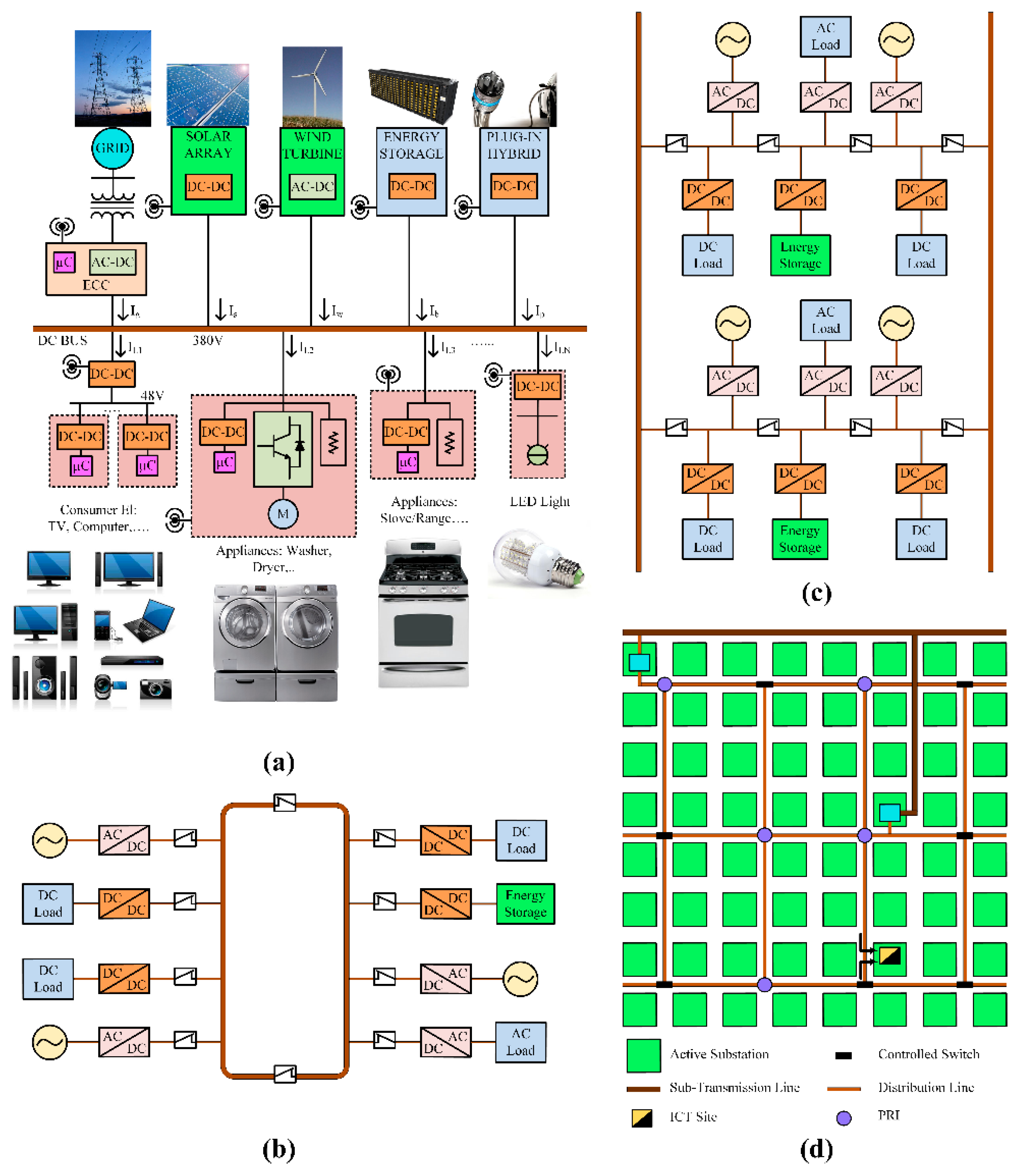
2.1. DC Bus Structures
2.1.1. Radial Bus Structure
2.1.2. Ring Bus Structure
2.1.3. Ladder Bus Structure
2.1.4. Meshed Bus Structure
2.2. Power Architectures
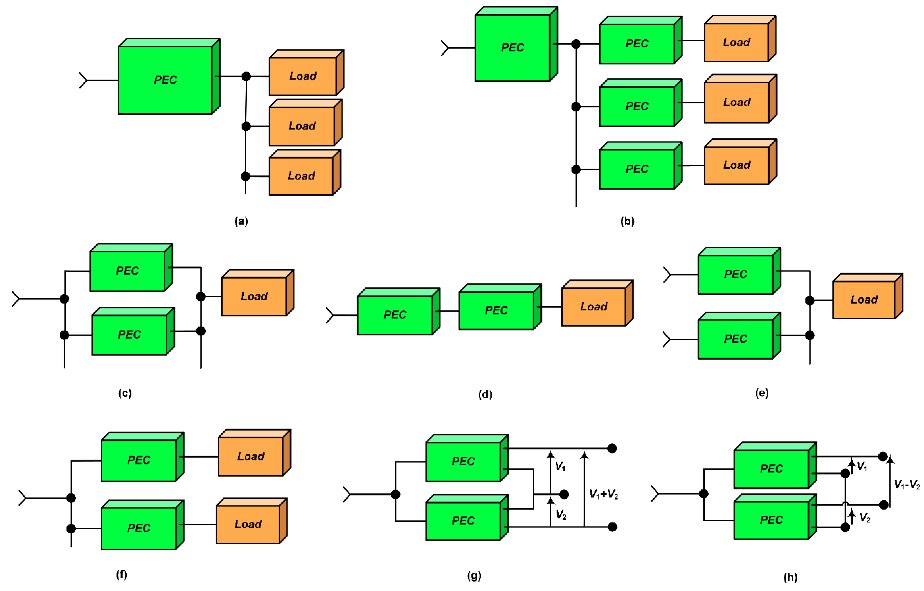
2.2.1. Paralleling
2.2.2. Cascading
2.2.3. Source Splitting
2.2.4. Load Splitting
2.2.5. Stacking
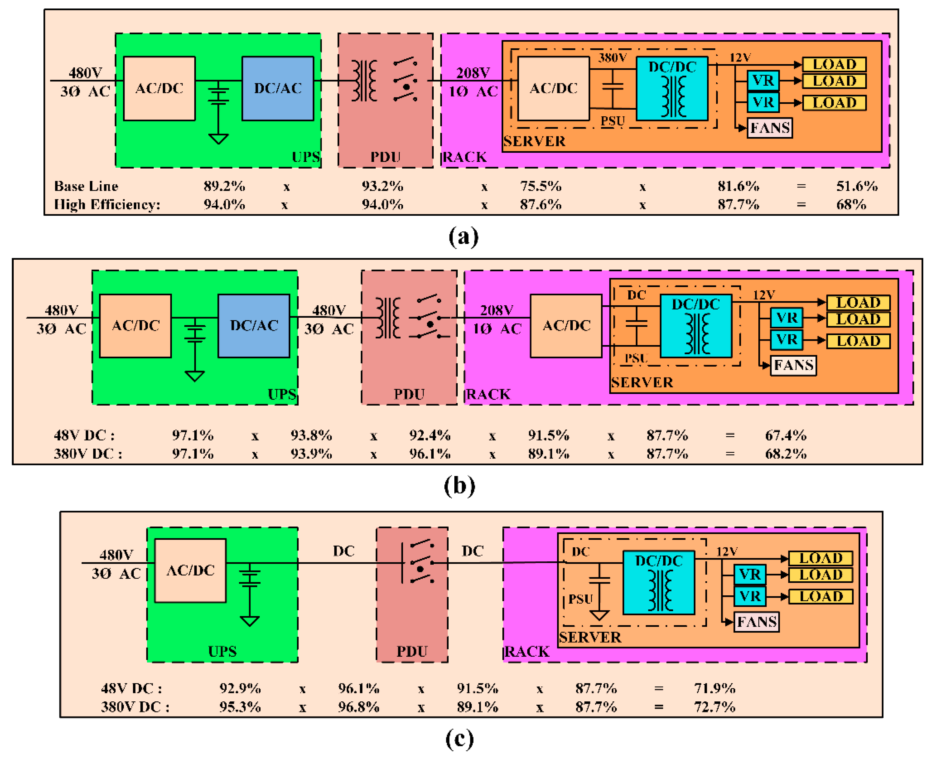
3. Efficiency
4. Safety and Protection
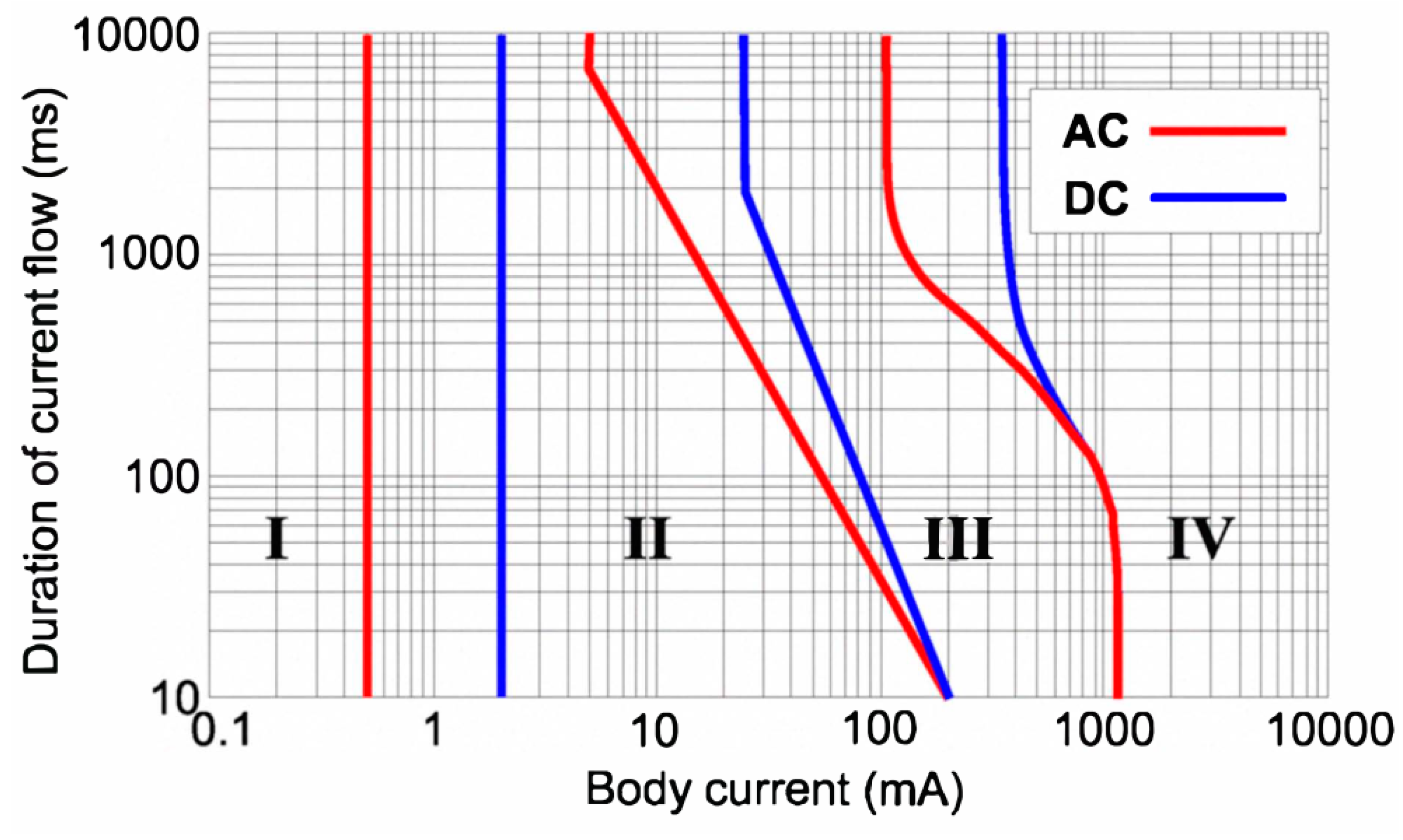
4.1. Personal Protection
- No effect
- A little pain but no dangerous effects
- Muscular contraction and respiratory compromise, which are reversible
- Critical effects such as ventricular fibrillation
4.2. Equipment Protection
4.3. Grounding Methods
4.3.1. Direct Grounding Method
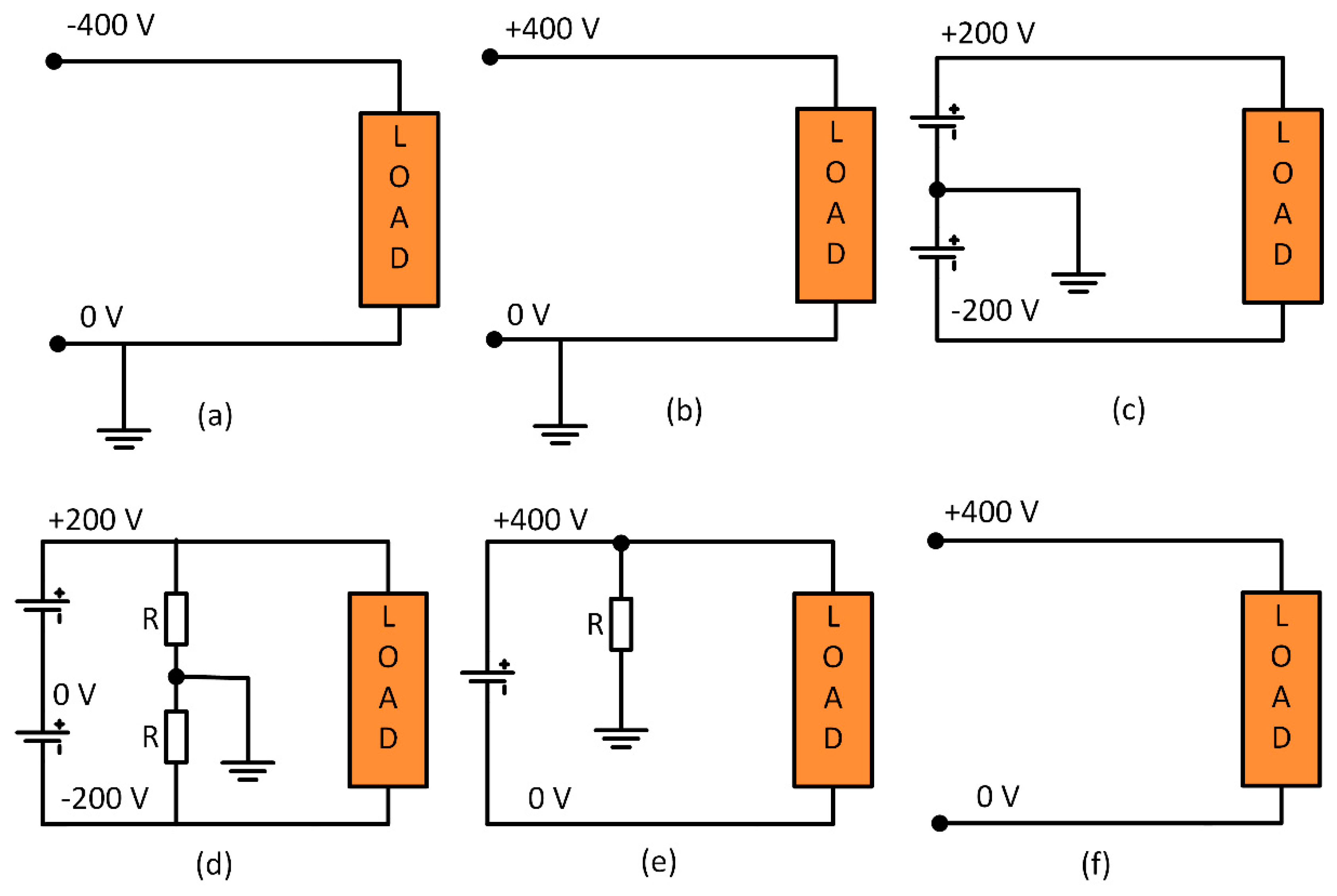
- Positive line grounding: In this system, the positive line is connected to ground as shown in Figure 6a. This system provides easy detection and breaking of current during a short circuit or earth fault. Monopole breaking is used to break the current. During a fault, the direction of the current through the human heart is upward and the heart-current factor F [39] is twice that of the direct negative grounding system. As a result, it seems like twice the current is flowing through the human body. The current one receives during an electric shock in this type of grounding is the largest among all the grounding systems as the circuit impedance is very low. However, as the fault current is large, it can be interrupted with better accuracy.
- Negative line grounding: In this type of grounding the negative line is connected to the ground as shown in Figure 6b. The properties of this grounding method are similar to positive line grounding. The current one receives in this type of grounding is usually high, but not as high as positive line grounding.
- Mid-point line grounding: In this type of grounding, the voltage to grounding is half of that compared to one end grounding as shown in Figure 6c. It is easy to detect and break currents during short circuit and ground faults. The current is usually large when short circuit or earth faults occur on the negative line. When breaking fault current, it is necessary to break both the positive and negative lines at the same time. Usually, rectifiers and batteries implement this type of grounding and hence they need to deal with higher initial costs.
4.3.2. Mid-Point Grounding with High Resistance
4.3.3. One-End Grounding with High Resistance
4.3.4. Floating System
5. Reliability
6. Cost
7. Voltage Level Selection
8. Global Market for DC Distribution Systems
9. Conclusions
Author Contributions
Conflicts of Interest
References
- Edison, T.A. System of Electrical Distribution. U.S. Patent 274,290, 28 August 1883. [Google Scholar]
- Sprague, F.J. System of Electrical Distribution. U.S. Patent 335,045, 26 January 1886. [Google Scholar]
- Pratt, A.; Kumar, P. Evaluation of direct current distribution in data centers to improve energy efficiency. Data Center J. 2007, 28. Available online: Https://pdfs.semanticscholar.org/7b81/222bc622c1fdf0847a708d97368d5c8da35e.pdf (accessed on 11 August 2018).
- Pratt, A.; Kumar, P.; Aldridge, T.V. Evaluation of 400V DC distribution in telco and data centers to improve energy efficiency. In Proceedings of the IEEE 29th International Telecommunications Energy Conference (INTELEC), Rome, Italy, 30 September–4 October 2007; pp. 32–39. [Google Scholar]
- Liu, Y.; Pratt, A.; Kumar, P.; Xu, M.; Lee, F.C. 390V Input VRM for High Efficiency Server Power Architecture. In Proceedings of the IEEE 22nd Applied Power Electronics Conference (APEC), Anaheim, CA, USA, 25 February–1 March 2007; pp. 1619–1624. [Google Scholar]
- Dehbonei, H.; Lee, S.R.; Nehrir, H. Direct Energy Transfer for High Efficiency Photovoltaic Energy Systems Part I: Concepts and Hypothesis. IEEE Trans. Aerosp. Electron. Syst. 2009, 45, 31–45. [Google Scholar] [CrossRef]
- Dehbonei, H.; Lee, S.R.; Ko, S.H. Direct Energy Transfer for High Efficiency Photovoltaic Energy Systems Part II: Experimental Evaluations. IEEE Trans. Aerosp. Electron. Syst. 2009, 45, 46–57. [Google Scholar] [CrossRef]
- Leey, J.P.; Min, B.; Kim, T.-J.; Yoo, D.-W.; Yoo, J.-Y. Input-Series-Output-Parallel Connected DC/DC Converter for a Photovoltaic PCS with High Efficiency under a Wide Load Range. J. Power Electron. 2010, 10, 9–13. [Google Scholar] [CrossRef]
- Liu, W.-S.; Chen, J.-F.; Liang, T.J.; Lin, R.L.; Liu, C.H. Analysis, Design, and Control of Bidirectional Cascoded Configuration for a Fuel Cell Hybrid Power System. IEEE Trans. Power Electron. 2010, 25, 1565–1575. [Google Scholar]
- Gummi, K.; Ferdowsi, M. Derivation of new double-input DC–DC converters using H-Bridge cells as building blocks. In Proceedings of the IEEE 34th Industrial Electronics Conference (IECON), Orlando, FL, USA, 10–13 November 2008; pp. 2806–2811. [Google Scholar]
- Prabhala, V.A.; Somayajula, D.; Ferdowsi, M. Power sharing in a double-input buck converter using dead-time control. In Proceedings of the IEEE Energy Conversion Congress and Exposition (ECCE), San Jose, CA, USA, 20–24 September 2009; pp. 2621–2626. [Google Scholar]
- Prabhala, V.A.K.; Fajri, P.; Gouribhatla, V.S.P.; Baddipadiga, B.P.; Ferdowsi, M. A DC–DC Converter with High Voltage Gain and Two Input Boost Stages. IEEE Trans. Power Electron. 2016, 31, 4206–4215. [Google Scholar] [CrossRef]
- Oliver, S. High-voltage DC distribution is key to increased system efficiency and renewable-energy opportunities. November 2012. Available online: http://www.vicorpower.com/documents/whitepapers/wp-High-voltage-DC-Distribution.pdf (accessed on 11 August 2018).
- Prabhala, V.A.K.; Baddipadiga, B.P.; Ferdowsi, M. DC distribution systems—An overview. In Proceedings of the IEEE International Conference on Renewable Energy Research and Application (ICRERA), Milwaukee, WI, USA, 19–22 October 2014. [Google Scholar]
- Kwasinski, A. Evaluation of dc Voltage Levels for Integrated Information Technology and Telecom Power Architectures. In Proceedings of the IEEE. 4th International Telecommunication—Energy Special Conference (TELESCON), Vienna, Austria, 10–13 May 2009; pp. 1–7. [Google Scholar]
- Boroyevich, D.; Cvetkovic, I.; Dong, D.; Burgos, R.; Fei, W.; Lee, F. Future electronic power distribution systems a contemplative view. In Proceedings of the IEEE 12th International Conference on Optimization of Electrical and Electronic Equipment (OPTIM), Basov, Romania, 20–22 May 2010; pp. 1369–1380. [Google Scholar]
- Mistry, K.M.; Silverman, E.; Taylor, T.; Willis, R. Telecommunications power architectures: Distributed or centralized. In Proceedings of the IEEE 11th International Telecommunications Energy Conference (INTELEC ’89), Florence, Italy, 15–18 October 1989. [Google Scholar]
- Margaritis, B.; Ide, P. Contemporary architectures for power systems considering future trends. In Proceedings of the IEEE 23rd International Telecommunications Energy Conference (INTELEC), Edinburgh, UK, 14–18 October 2001; pp. 525–531. [Google Scholar]
- Cividino, L. Power system architecture’s for the emerging information highway. In Proceedings of the IEEE 16th International Telecommunications Energy Conference (INTELEC’94), Vancouver, BC, USA, 30 October–3 November 1994; pp. 90–97. [Google Scholar]
- Xu, C.D.; Cheng, K.W.E. A survey of distributed power system—AC versus DC distributed power system. In Proceedings of the IEEE 4th International Conference on Power Electronics Systems and Applications (PESA), Hong Kong, China, 8–10 June 2011; pp. 1–12. [Google Scholar]
- Luo, S.; Batarseh, I. A review of distributed power systems part I: DC distributed power system. IEEE Aerosp. Electron. Syst. Mag. 2005, 20, 5–16. [Google Scholar] [CrossRef]
- Tabisz, W.A.; Jovanovic, M.M.; Lee, F.C. Present and future of distributed power systems. In Proceedings of the IEEE 7th Applied Power Electronics Conference and Exposition (APEC ’92), Boston, MA, USA, 23–27 February 1992; pp. 11–18. [Google Scholar]
- Peng, W.; Goel, L.; Xiong, L.; Hoong, C.F. Harmonizing AC and DC: A Hybrid AC/DC Future Grid Solution. IEEE Power Energy Mag. 2013, 11, 76–83. [Google Scholar] [CrossRef]
- AlLee, G.; Tschudi, W. Edison Redux: 380 Vdc Brings Reliability and Efficiency to Sustainable Data Centers. IEEE Power Energy Mag. 2012, 10, 50–59. [Google Scholar] [CrossRef]
- Rasmussen, N.; Spitaels, J. A Quantitative Comparison of High Efficiency ac VS. Dc Power Distribution for Data Centers. APC White Paper 127. 2006. Available online: https://www.anixter.com/content/dam/Suppliers/APC/White%20Paper/A%20Quantitatve%20Comparison.pdf (accessed on 11 August 2018).
- Huey, P.; Lo, E.; Pong, B. DC Electrical Distribution Systems in Buildings. In Proceedings of the IEEE International Conference on Power Electronics Systems and Applications (ICPESA ’06), Hong Kong, China, 12–14 November 2006; pp. 115–119. [Google Scholar]
- Hammerstrom, D.J. AC Versus DC Distribution Systems—Did We Get it Right? In Proceedings of the Power Engineering Society General Meeting, Tampa, FL, USA, 12–14 June 2007; pp. 1–5. [Google Scholar]
- Hirose, K.; Takeda, T.; Muroyama, S. Study on Field Demonstration of Multiple Power Quality Levels System in Sendai. In Proceedings of the IEEE 28th International Telecommunications Energy Conference (INTELEC ’06), Providence, RI, USA, 10–14 September 2006; pp. 1–6. [Google Scholar]
- Allen, W.; Natale, S.V. Achieving ultra-high system availability in a battery-less -48VDC power plant. In Proceedings of the IEEE 24th International Telecommunications Energy Conference (INTELEC), Montreal, QC, Canada, 29 September–3 October 2002; pp. 287–294. [Google Scholar]
- Foster, C.; Dickinson, M. High voltage DC power distribution for telecommunications facilities. In Proceedings of the IEEE 30th International Telecommunications Energy Conference (INTELEC), San Diego, CA, USA, 14–18 September 2008; pp. 1–4. [Google Scholar]
- Yamashita, T.; Muroyama, S.; Furubo, S.; Ohtsu, S. 270 V DC system-a highly efficient and reliable power supply system for both telecom and datacom systems. In Proceedings of the IEEE 21st International Telecommunication Energy Conference (INTELEC ’99), Copenhagen, Denmark, 9 June 1999. [Google Scholar]
- Carlsson, U.; Flodin, M.; Akerlund, J.; Ericsson, A. Powering the Internet—Broadband equipment in all facilities—The need for a 300 V DC powering and universal current option. In Proceedings of the IEEE 25th International Telecommunications Energy Conference (INTELEC ’03), Yokohama, Japan, 23 October 2003; pp. 164–169. [Google Scholar]
- Akerlund, J.; Gennas, C.B.A.; Ohlsson, G.; Rosin, D. One year operation of a 9 kW HVDC UPS 350 v at Gnesta municipality data center. In Proceedings of the IEEE 29th International Telecommunications Energy Conference (INTELEC), Rome, Italy, 30 September–4 October 2007; pp. 40–45. [Google Scholar]
- Engelen, K.; Shun, E.L.; Vermeyen, P.; Pardon, I.; D’Hulst, R.; Driesen, J. The Feasibility of Small-Scale Residential DC Distribution Systems. In Proceedings of the IEEE Conference on Industrial Electronics (IECON), Paris, French, 6–10 November 2006; pp. 2618–2623. [Google Scholar]
- Lee, P.W.; Lee, Y.Z.; Lin, B.T. Power distribution systems for future homes. In Proceedings of the IEEE International Conference on Power Electronics and Drive Systems (PEDS ’99), Hong Kong, China, 27–29 July 1999; Volume 2, pp. 1140–1146. [Google Scholar]
- Gross, P.; Godrich, K.L. Total DC Integrated Data Centers. In Proceedings of the IEEE 27th International Telecommunications Conference (INTELEC ’05), Berlin, Germany, 18–22 September 2005; pp. 125–130. [Google Scholar]
- Hirose, K.; Tanaka, T.; Babasaki, T.; Person, S.; Foucault, O.; Sonnenberg, B.J. Grounding concept considerations and recommendations for 400VDC distribution system. In Proceedings of the IEEE 33rd International Telecommunications Energy Conference (INTELEC), Amsterdam, The Netherlands, 9–13 October 2011; pp. 1–8. [Google Scholar]
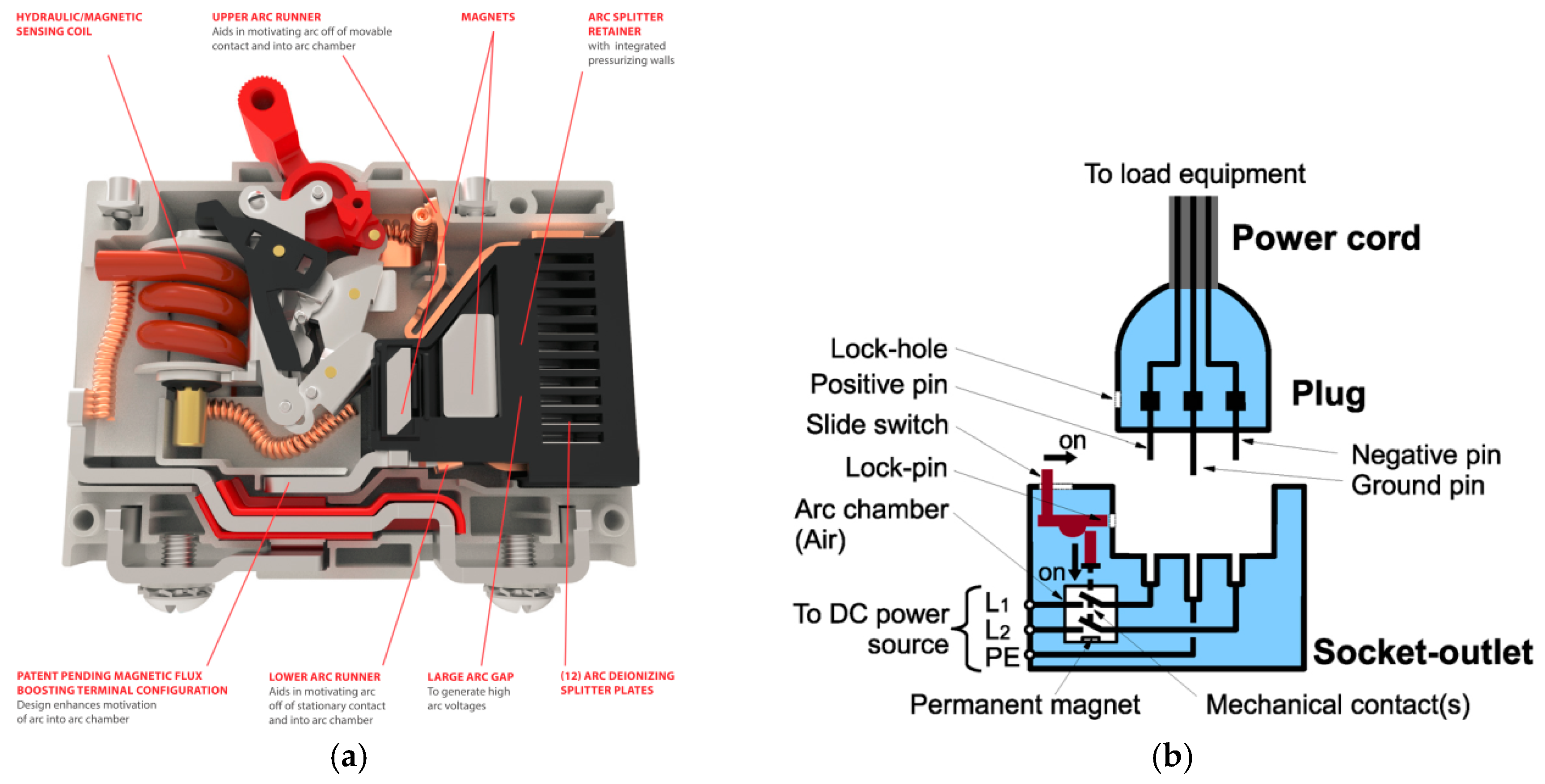
- Seungseok, B.; Yuba, T.; Kiryu, K.; Nakamura, A.; Miyazawa, H.; Noritake, M. Development of plug and socket-outlet for 400 volts direct current distribution system. In Proceedings of the IEEE 8th International conference on Power Electronics and ECCE Asia (ICPE & ECCE), Jeju, Korea, 30 May–3 June 2011; pp. 218–222. [Google Scholar]
- Noritake, M.; Iino, T.; Fukui, A.; Hirose, K.; Yamasaki, M. A study of the safety of the DC 400 V distribution system. In Proceedings of the IEEE 31st International Telecommunications Energy Conference (INTELEC), Incheon, Korea, 18–22 October 2009; pp. 1–6. [Google Scholar]
- Hirose, K. DC power demonstrations in Japan. In Proceedings of the IEEE 8th International Conference on Power Electronics and ECCE Asia (ICPE & ECCE), Jeju, Korea, 30 May–3 June 2011; pp. 242–247. [Google Scholar]
- Hernandez, J.C.; Vidal, P.G.; Medina, A. Characterization of the insulation and leakage currents of PV generators: Relevance for human safety. Renew. Energy 2010, 35, 593–601. [Google Scholar] [CrossRef]
- Hernandez, J.C.; Vidal, P.G. Analysis of PV Generator Insulation and Leakage Currents. Relevance for Personal Safety. In Proceedings of the 19th European Photovoltaic Solar Energy Conference, Paris, French, 7–11 June 2004; pp. 2587–2590. [Google Scholar]
- Medina, A.; Hernandez, J.C.; Ortega, M.J.; Jurado, F. DC current injection into the network from transformerless and LF transformer photovoltaic inverters. In Proceedings of the 16th International Conference on Harmonics and Quality of Power (ICHQP), Bucharest, Romania, 25–28 May 2014. [Google Scholar]
- Hernandez, J.C.; Sutil, F.S.; Vidal, P.G. Protection of a multiterminal DC compact node feeding electric vehicles on electric railway systems, secondary distribution networks, and PV systems. Turkish J. Elect. Eng. Comput. Sci. 2016, 24, 3123–3143. [Google Scholar] [CrossRef]
- Carling, I. Technologies (2015)—DC Circuit Breaker. Available online: http://www.carlingtech.com/sites/default/files/documents/CX-Series_Details_%26_COS_010714.pdf (accessed on 11 August 2018).
- Inttpat, P.; Paisuwanna, P.; Khomfoi, S. Capacitor lifetime monitoring for multilevel modular capacitor clamped DC to DC converter. In Proceedings of the IEEE 8th International Conference on Electrical Engineering/Electronics, Computer, Telecommunications and Information Technology (ECTI-CON), Khon Kaen, Thailand, 17–19 May 2011; pp. 719–722. [Google Scholar]
- Becker, D.J.; Sonnenberg, B.J. DC microgrids in buildings and data centers. In Proceedings of the IEEE 33rd International Telecommunications Energy Conference (INTELEC), Amsterdam, The Netherlands, 9–13 October 2011; pp. 1–7. [Google Scholar]
- Talapko, D. Telecom datacenter power infrastructure availability comparison of DC and AC UPS. In Proceedings of the IEEE International Telecommunications Energy Conference (INTELEC), Scottsdale, AZ, USA, 30 September–4 October 2012. [Google Scholar]
- Sithimolada, V.; Sauer, P.W. Facility-level DC vs. typical ac distribution for data centers: A comparative reliability study. In Proceedings of the IEEE Region 10 Conference (TENCON), Fukuoka, Japan, 21–24 November 2010. [Google Scholar]
- Bodi, F.; Hui, L.E. 380/400V DC powering option. In Proceedings of the IEEE 33rd International Telecommunications Energy Conference (INTELEC), Amsterdam, The Netherlands, 9–13 October 2011; pp. 1–8. [Google Scholar]
- Matsumoto, A.; Fukui, A.; Takeda, T.; Hirose, K.; Yamasaki, M. Development of 400 Vdc power distribution system and 400 Vdc output rectifier. In Proceedings of the IEEE 31st International Telecommunications Energy Conference (INTELEC), Incheon, Korea, 18–22 October 2009; pp. 1–5. [Google Scholar]
- Sannino, A.; Postiglione, G.; Bollen, M.H.J. Feasibility of a DC network for commercial facilities. IEEE Trans. Ind. Appl. 2003, 39, 1499–1507. [Google Scholar] [CrossRef]
- Patterson, B. DC Power Distribution Systems. 25 February 2015. Available online: http://www.emergealliance.org/Portals/_default/Knowledgebase/1/150225%20Strategies%20in%20Light_The%20LED%20Show_BTP.pdf (accessed on 11 August 2018).
- Patterson, B.; Hamborsky, D. Net Zero Strategies for Existing Buildings. 21 June 2013. Available online: http://emergealliance.org/Portals/_default/Knowledgebase/1/NetZeroStrategiesforExistingBuildings_21421_1.pdf (accessed on 11 August 2018).
- Patterson, B.; Symanski, D. The Nation’s Quest for Net Zero Energy Buildings: DC Distribution—The Power to Change Buildings. Lawrence Berkeley National Labs Seminar, 14 July 2011. Available online: http://portal.emergealliance.org/DesktopModules/Inventure_Document/FileDownload.aspx?ContentID=20624 (accessed on 11 August 2018).
- Boeke, U.; Wendt, M. DC power grids for buildings. In Proceedings of the IEEE First International Conference on DC Microgrids (ICDCM), Atlanta, GA, USA, 24–27 May 2015; pp. 210–214. [Google Scholar]
- Vossos, V.; Garbesi, K.; Shen, H. Energy Savings from Direct-DC in U.S. Residential Buildings. Energy Build. 2014, 68, 223–231. [Google Scholar] [CrossRef]


| System Features | Radial Bus | Ring Bus | Ladder Bus | Meshed Bus |
|---|---|---|---|---|
| Power Reliability | Very Low | Moderate | High | Very High |
| No. of Components | Low | Moderate | High | Very High |
| Cost | Very Low | Low | Moderate | Very High |
| System | Source | DC Load | AC Load | ACwC Load |
|---|---|---|---|---|
| AC | DC | DC–AC–DC | DC–AC | DC–AC–DC–AC |
| AC | AC–DC | - | AC–DC–AC | |
| DC | DC | - | DC–AC | DC–AC |
| AC | AC–DC | AC–DC–AC | AC–DC–AC |
| System | Uninterruptible Power Supply (UPS) | Distribution | IT Power Supply | Overall Efficiency |
|---|---|---|---|---|
| 480 to 208 Vac | 96.20% | 96.52% | 90.00% | 83.56% |
| 400/230 Vac | 96.20% | 99.50% | 90.25% | 86.39% |
| 48 Vdc | 92.86% | 99.50% | 91.54% | 84.58% |
| 380 Vdc | 96.00% | 99.50% | 91.75% | 87.64% |
| Hybrid 575 Vdc | 95.32% | 92.54% | 91.54% | 80.74% |
| Year | Country | Organization | Voltage Level |
|---|---|---|---|
| 2009 | United States | Intel Corporation | 400 Vdc |
| University of California, San Diego (UCSD) | 380 Vdc | ||
| Validus (ABB) | 550 Vdc | ||
| France | France Telecom | 350 Vdc | |
| Sweden | UPN AB. | 350 Vdc | |
| Japan | NTT group | 380/400 Vdc | |
| New Zealand | Telecom NZ | 220 Vdc | |
| 2014 | United States | SAP | 380 Vdc |
| Intel Corporation | |||
| Stanford University | |||
| IO | |||
| University of California, San Diego (UCSD) | |||
| Duke Energy | |||
| Clustered Systems | |||
| NEXTEK | |||
| IBM | |||
| Validus (ABB) | |||
| Syracuse University | |||
| Steel Ocra | |||
| North America Telecom | |||
| Canada | Canada Telecom Operator | ||
| France | France Telecom | ||
| Swiss | Green.Ch, ABB | ||
| India | IBM | ||
| Taiwan | Taiwan IT | ||
| Singapore | IBM | ||
| China | China Mobile | ||
| New Zealand | Telecom NZ | ||
| Japan | NTT Group | 380/400 Vdc | |
| Norway | UPN AB | 350/380 Vdc | |
| Sweden | Netpower Labs AB | 350/380 Vdc | |
| Korea | - | 300/380 Vdc | |
| China | China Telecom | 240/380 Vdc |
| Standard | Description |
|---|---|
| ETSI EN 300 132-3 | Power supply interface at the input to telecommunications equipment |
| ETSI EN 301 605 | Earthing and bonding of 400 Vdc data and telecom (ICT) equipment |
| ITU-T L.1200 | Direct current power feeding interface up to 400 Vdc at the input to telecommunication and ICT equipment |
| YD/T 2378-2011 | 240 Vdc power supply system for telecommunications |
| EMerge Alliance Data/Telecom Center Standard | Creates an integrated, open platform for power, infrastructure, peripheral device and control applications to facilitate the hybrid use of AC and DC power within data centers and telecommunications central offices |
| IEC 61984 | Connectors—Safety requirements and tests |
| UL 1977 | Components connectors for use in data, signal, control, and power applications |
| IEC 60950 | Information technology equipment—Safety |
| UL 60950 | Safety for information technology equipment |
| IEC 60644-1 | Insulation coordination for equipment within low-voltage systems |
| IEC/TC 64 | Electrical installations and protection against electric shock |
| UL 62040-5 | DC UPS standard |
| Product | Manufacturers |
|---|---|
| DC power system | Emerson, ABB, Delta, Netpower Labs, Eltek, Rectifier Technologies Ltd. (Australia), Japanese vendors, Chinese vendors |
| DC Breaker | ABB, Carling, Schneider, Nader, Siemens |
| Bus way | Starline, PDI, Eaton |
| Rack PDU | Server Tech, API Tech, Delta, Fujitsu Components, Echola |
| Connectors | Anderson, Hubbel, Rong Feng/Delta, Fujitsu Components |
| Rack-Mount Power Supply | Emerson, Delta, AcBel, others |
| Power Components | Vicor |
| ICT Load | HP, IBM, Juniper, NEI, NEC, Supermico |
© 2018 by the authors. Licensee MDPI, Basel, Switzerland. This article is an open access article distributed under the terms and conditions of the Creative Commons Attribution (CC BY) license (http://creativecommons.org/licenses/by/4.0/).
Share and Cite
Prabhala, V.A.; Baddipadiga, B.P.; Fajri, P.; Ferdowsi, M. An Overview of Direct Current Distribution System Architectures & Benefits. Energies 2018, 11, 2463. https://doi.org/10.3390/en11092463
Prabhala VA, Baddipadiga BP, Fajri P, Ferdowsi M. An Overview of Direct Current Distribution System Architectures & Benefits. Energies. 2018; 11(9):2463. https://doi.org/10.3390/en11092463
Chicago/Turabian StylePrabhala, Venkata Anand, Bhanu Prashant Baddipadiga, Poria Fajri, and Mehdi Ferdowsi. 2018. "An Overview of Direct Current Distribution System Architectures & Benefits" Energies 11, no. 9: 2463. https://doi.org/10.3390/en11092463
APA StylePrabhala, V. A., Baddipadiga, B. P., Fajri, P., & Ferdowsi, M. (2018). An Overview of Direct Current Distribution System Architectures & Benefits. Energies, 11(9), 2463. https://doi.org/10.3390/en11092463