Abstract
The dual-redundancy permanent magnet synchronous motor (DRPMSM) has high reliability in its applications. Compared with the traditional permanent magnet synchronous motor (PMSM), small teeth were added to the stator in DRPMSM and its vibration has new characteristics. This paper derived the analytic expression of the radial electromagnetic force for PMSM in the air gap based on the Maxwell stress equation and summarized its sources. The simplified stator teeth model of the traditional PMSM and DRPMSM were established in 12-slot/10-pole (12s10p), and the analytical expression and Fourier expansion of radial electromagnetic force on the teeth were given. The electromagnetic and structural finite element models of the motor were established, and analyses of modal and harmonic response were carried out. The simulation results show that the stator vibration amplitude of DRPMSM is smaller than that of traditional PMSM at no-load and is also bigger under rated load. Furthermore, in order to guarantee the low amplitude of stator vibration under rated load for DRPMSM, the width of the small teeth should be smaller.
1. Introduction
The permanent magnet synchronous motor (PMSM) has been widely applied in various fields due to its simple structure, high power density, and reliable operation [1,2,3,4,5,6,7,8,9,10]. In this paper, a dual-redundancy permanent magnet synchronous motor (DRPMSM) with no electromagnetic coupling and low heat coupling between phase windings was evolved from PMSM of 12-slot/10-pole (12s10p). By adding six small teeth in the common slot center of the two adjacent phase windings, the leakage inductance between the different phase windings was basically eliminated and the thermal coupling between the phase windings was reduced by means of appending the heat insulation plate on both sides of the small teeth [11,12,13]. Two sets of three-phase symmetrical windings with star connection and the same phase of electromotive force were arranged on the DRPMSM. Under normal conditions, both of them work at the same time in double redundancy. When one of the three-phase windings malfunctions, its power supply is stopped and another normal three-phase winding continues to work.
The application of DRPMSM as the drive in the military field requires low vibration. Electromagnetic vibration is a main source of motor vibration and scholars worldwide have studied it in depth. Considering the influence of permanent magnet shape on motor vibration, by optimizing the shape of the permanent magnet, the amplitude of motor vibration can be reduced [14]. In reference [15], the finite element model was used to analyze the effect of stator teeth, slot wedge, and armature winding on the natural frequency of the stator. For the special purpose of PMSM in the operation of variable frequency, the amplitude of vibration can be reduced by eliminating the radial electromagnetic force of specific frequencies [16]. Resonance occurs when the radial electromagnetic force is consistent with the modal frequency of the stator and will lead to great vibration and noise [17]. It is interesting to note that the vibration affecting permanent magnets on the motor is higher than the rated load in PMSM [18]. It has been recognized in [18,19,20,21,22,23,24] that the vibration and noise of a motor can be reduced by changing the pole-slot match to raise the minimum mode of the radial electromagnetic force.
The different parameters affecting the vibration of the motor have been studied in depth through the method of theoretical derivation [14,15,16,17,18,19,20,21,22,23,24] and are also demonstrated in Section 3 but with more details on a different object. On the basis of the abovementioned research, the radial electromagnetic force on the yoke equivalent to the superposition of different order force waves and the influence of extra small teeth on vibration in DRPMSM are analyzed in this paper.
2. The Structure and the Parameters of DRPMSM
The stator profile are shown in Figure 1. Both of them have the same rotor structure, and the main parameters are shown in Table 1.
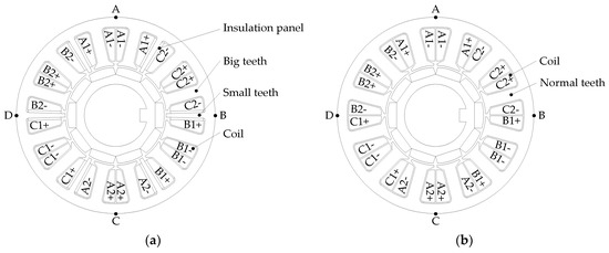
Figure 1.
The stator profile: (a) dual-redundancy permanent magnet synchronous motor; (b) the traditional permanent magnet synchronous motor without small teeth.

Table 1.
The main parameters.
Since the slot leakage flux of coils get closed through the small teeth in the common slot center of the two adjacent phase windings, the leakage inductance between the different phase windings are basically eliminated and the insulation panel placed on both sides of the small teeth can weaken the thermal coupling among different phase windings. Assuming that the mechanical angle of the small teeth is b, the star graphs of the fundamental electromotive force for DRPMSM and traditional PMSM without small teeth are shown in Figure 2.
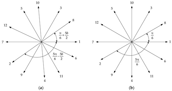
Figure 2.
The star graphs of the fundamental electromotive force: (a) DRPMSM; (b) the traditional PMSM without small teeth.
3. Analysis of the Radial Electromagnetic Force
3.1. Derivation of the Magnetic Field in Air Gap
Assuming that the inner surface of the stator is smooth, the permanent magnetic field contains only the odd harmonics. The pole-pairs of the permanent magnetic field are given by
where is the number of the permanent pole when , .
When the fundamental frequency of the stator current is , the fundamental angular frequency is . The magnetomotive force of the permanent magnetic field in air gap (unit: A) is described as
where (unit: A) is the amplitude of ; (unit: rad) is the angular position of the rotor, measured in mechanical radian from the center of one of the permanent magnet; and the permanent magnetic field frequency of the pole-pairs can be described by
The time harmonic order of the stator current are given by
The pole-pairs of the magnetic field produced by the armature reaction are given by
The magnetomotive force by the armature reaction in air gap (unit: A) is described as
where (unit: A) is the amplitude of , (unit: rad) is the phase angle of corresponding to with and , and (unit: rad) is the angular position of stator, measured in mechanical radian from the center of two big teeth.
According to Equation (6), when , the rotation of the magnetomotive force is positive, and when , it is negative. When , the rotation of the magnetomotive force is negative, and when , it is positive.
Considering the opening of the stator slot, the coordinate origin is the intersection between the line of the big (or normal) teeth center and the stator inner diameter, and the magnetic conductance at air gap (unit: H−1) are given by
where is the average conductance of the magnetic field in air gap, is the amplitude of the order harmonic of air gap magnetic conductance, and Z is the number of the stator slot.
According to Equations (2) and (7), the permanent magnetic field in air gap (unit: T) can be described by
where , .
According to Equations (6) and (7), the magnetic field by the armature reaction in air gap (unit: T) can be described by
where , .
3.2. The Theoretical Derivation of the Radial Electromagnetic Force
According to the Maxwell stress equations, the radial electromagnetic force in air gap can be expressed as
where and are the radial and tangential components of the magnetic field in the air gap, .
Since the value of is much smaller than , can be reduced to
For the formulas for and considering only the radial components above, can be described by
where the radial electromagnetic forces in air gap are produced by the permanent magnetic field alone, by the armature reaction magnetic field alone, and by the interaction between the permanent magnetic field and the armature reaction magnetic field.
According to Equation (12), when the fundamental frequency of the stator current is and the harmonic of air gap magnetic conductance is equal to 1, the exciting mode number and frequency of can be obtained, as listed in Table 2.
Table 2.
The exciting mode number and frequency of .
3.3. Magnetic Field in Air Gap of 12s10p
When the fundamental current frequency of 12s10p is and the harmonic of air gap magnetic conductance is equal to 1, according to Equation (12), the exciting mode number and the frequency times of the radial electromagnetic force produced by permanent magnetic field , armature reaction magnetic field , and the interaction between permanent magnetic field and armature reaction magnetic field can be obtained, as listed in Table 3, Table 4 and Table 5.
Table 3.
The radial electromagnetic force in the air gap produced by the permanent magnetic field (mode number/frequency times).
Table 4.
The radial electromagnetic force in the air gap produced by the armature reaction magnetic field alone (mode number/frequency times).
Table 5.
The radial electromagnetic force in the air gap produced by the interaction between the permanent magnetic field and the armature reaction magnetic field (mode number/frequency times).
According to Equation (8), the pole-pair numbers of radial electromagnetic force consist of and in Table 3. When , , and .
The mechanical angle of the stator slot opening b was 3.76°. For Cases 1–4, the mechanical angle of the small teeth a were 0°, 2°, 3.76°, and 5.63° (Case1: a = 0°, b = 3.76°; Case2: a = 2°, b = 3.76°; Case3: a = 3.76°, b = 3.76°; Case4: a = 5.63°, b = 3.76°). The amplitude of the radial magnetic field by the permanent magnet and armature reaction alone at rated load obtained by finite element analysis are shown in Table 6 and Table 7.
Table 6.
The amplitude of the radial magnetic field by the permanent magnet in the air gap (unit: T).
Table 7.
The amplitude of the radial magnetic field by the armature reaction on rated load alone in the air gap (unit: T).
The radial electromagnetic force in the air gap will affect the radial electromagnetic force on the stator teeth directly. The mode number of the radial electromagnetic force l is equal to 0, 2, 4, 6, 8... only, according to Table 3, Table 4 and Table 5. When l is equal to 0, the excitation frequency is far away from the resonance frequency, so it will not cause big vibration noise, and for the 2nd, 4th, 6th, 8th, 10th, 12th and 14th order, its amplitude curve of the radial electromagnetic force in the air gap with the load times can be obtained by the 2D finite element, as shown in Figure 3 (2D diagrams) and 4 (3D diagrams). The four different colors in the diagram correspond to Cases 1–4.
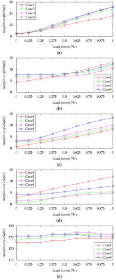
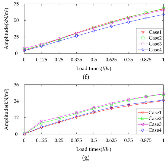
Figure 3.
The amplitude curve of the radial electromagnetic force in the air gap with the load times (2D diagrams): (a) l = 2; (b) l = 4; (c) l = 6; (d) l = 8; (e) l = 10; (f) l = 12; (g) l = 14.
With the increase of the load times, the amplitude of the magnetic field in the air gap generated by the armature reaction increases, so the amplitude of the radial electromagnetic force become larger by the armature reaction magnetic field and by the interaction between the permanent magnetic field and the armature reaction magnetic field. Hence, the amplitude of the radial force in the air gap on l = 2, 4, 6, 8, 12 and 14 increases.
The amplitudes of the 2nd-, 12th-, and 14th-order radial forces are higher than that of the 4th-, 6th-, and 8th-order radial forces, and the amplitude of the 10th-order radial force is basically unchangeable.
In the four cases of the same mode, the amplitudes of the radial forces in the air gap display few differences, as shown in Figure 3 and Figure 4.
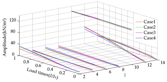
Figure 4.
The amplitude curve of the radial electromagnetic force in the air gap with the load times (3D diagrams).
It is known from Table 3, Table 4, Table 5, Table 6 and Table 7 that the amplitude of the magnetic field which can produce 2nd-, 10th-, and 12th-order radial electromagnetic forces is larger than that of 4th-, 6th-, and 8th-order forces, so the amplitude of the 2nd-, 10th-, and 12th-order radial forces is higher than that of the 4th, 6th, and 8th order, as shown in Figure 3 and Figure 4. According to Table 6 and Table 7, the amplitude of the armature reaction magnetic field is far less than that of the permanent magnetic field, so the amplitude of the 10th-order radial force does not change following the load times (Figure 3e). In Table 7, the magnetic field amplitudes of are as big as that of , so the amplitudes of the 14th-order radial force are higher than that of the 4th-, 6th-, and 8th-order, as shown in Figure 3 and Figure 4.
4. The Influence of Small Teeth on Radial Electromagnetic Force
The simplified slot diagram of the stator in 12s10p is shown in Figure 5, where , , , , , , , , , .
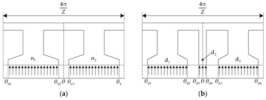
Figure 5.
The simplified slot diagram of the stator in 12-slot/10-pole (12s10p): (a) a = 0°, b = 3.76°; (b) a = 2°, 3.76°, 5.63°, b = 3.76°.
Assuming that the amplitude of radial electromagnetic force on the stator teeth surface is identical, the lth-order radial force in air gap is described as
where the amplitude of the lth-order radial electromagnetic force in the air gap is , and its frequency times of the lth-order radial force is .
Because the stator silicon-steel was rigid, the radial electromagnetic force on the stator teeth was calculated by the average value as
where the average value of the order radial electromagnetic force on teeth number (in Figure 5) is (unit: N/m2) and (unit: rad) is its angular position.
The average teeth forces are given by
where , , , .
The amplitudes of the average force on the stator teeth in four cases are shown in Table 8.
Table 8.
The amplitude of the average force on the stator teeth in four cases.
The radial electromagnetic force on the stator teeth is transmitted to the stator yoke through the stator teeth. The amplitude of the radial electromagnetic force on the stator yoke with teeth is unequal to 0 and equal to 0 on the stator yoke without teeth, so the radial electromagnetic force acting on the stator yoke is periodic, continuous, and bounded during the period and conforms to the condition of Fourier expansion.
It can be equivalent to the superposition of different order force waves applied on the inner surface of the stator yoke. is described as
where the ratio of stator teeth width to stator tip width is , and its value is variable for the different stator teeth. is the order Fourier expansion coefficient of the . is the amplitude of , so is the amplitude of the radial electromagnetic force on the inner surface of the stator yoke. can be obtained by
The relation between the mode number and amplitude of deformation for can be expressed as [21]
where is the amplitude of the deformation caused by mode of the radial electromagnetic force on the stator yoke, is the coefficient determined by dimensions and structural properties of the stator, and is the amplitude of mode in radial electromagnetic force density distribution.
In fact, this basic formula cannot be used for accurate calculation and a detailed finite element structural analysis is needed. However, for a rough comparison, it is beneficial to use Equation (22) to study the resultant amplitude of the deformation caused by the radial electromagnetic force. When is constant, as shown in Equation (22), decreases with .
In this paper, is considered to be equal to and is considered to be equal to .
According to Equations (14)–(22), the Fourier expansion of radial electromagnetic force on the inner surface of stator yoke with different widths can be obtained, as shown in Table 9.
Table 9.
Fourier expansion of in Cases 1–4.
In Table 9, with the same structure of the stator, small teeth (yes) stands for the radial electromagnetic force acting on big teeth and small teeth together, and small teeth (no) stands for that on big teeth alone.
Table 9 shows that, for the radial electromagnetic force on the stator yoke , when the order l is equal to 2, 10, 14, the amplitude of obtained by Fourier expansion is higher, so the amplitude of the order radial electromagnetic force on the inner surface of the stator yoke is higher. When the order l is equal to 4, 8, the amplitude of is higher, so the amplitude of the order radial electromagnetic force on the inner surface of the stator yoke is higher. When the order l is equal to 6, 12, the amplitude of is higher, so the amplitude of the order radial electromagnetic force on the inner surface of the stator yoke is higher. According to Figure 3 and Figure 4 and Table 9, the amplitude of (l = 2, 10) is much bigger than that of (l = 4, 6, 8, 12, 14), (l = 2, 4, 6, 8, 10, 12, 14), and (l = 2, 4, 6, 8, 10, 12, 14), so (l = 2, 10) can be considered only below.
For , the amplitude of (l = 2, 10) increases with the small teeth width increasing on condition that the radial electromagnetic force on the big teeth only work. When l = 2, the radial electromagnetic force on the small teeth raises the amplitude of , and the larger the small teeth width, the larger the amplitude of , so the amplitude in increases. When l = 10, the radial electromagnetic force on the small teeth decreases the amplitude of , and the larger the small teeth width, the smaller the amplitude of , so the amplitude in decreases. For (l = 2, 10), its excited radial electromagnetic force frequencies are mainly 2f (600 Hz), as shown in Table 3, Table 4 and Table 5.
5. Influence of Small Teeth on Electromagnetic Vibration
5.1. Modal Analysis of Stator
It was important that the modal analysis of the stator structure is completed. This determined whether the resonance occurred on the stator when the frequencies of the radial harmonic components of electromagnetic force coincided with the modal frequencies of the stator.
The motion differential equation determined by the state vector method as follows [24]:
where is the mass matrices, is the damping matrices, is the stiffness matrices, is the displacement vector, and is the radial electromagnetic force vector.
Because of the shell, the armature windings and rigid support affected the natural frequency of the mode. Thus, only the stator was considered, and it was assumed that the stator was completely unconstrained. The models of the three-dimensional stators of PMSM in different cases are shown in Figure 6.
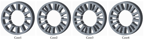
Figure 6.
The model of the three-dimensional stator of PMSM.
The material of the stator was DW310-35, its stacking coefficient was 0.95, and its length was 142 mm. The mode of the stator in 12s10p and its resonant frequencies of the 2nd and 4th orders were obtained by modal simulation, as shown in Figure 7.
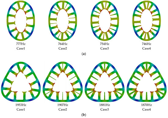
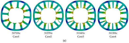
Figure 7.
The stator mode and its resonant frequencies on the different small teeth width: (a) 2nd-order; (b) 3rd-order; (c) 4th-order.
Compared with the resonant frequencies of the different small teeth width in Figure 7, it was found that the resonant frequencies of the same mode order decreased weakly in Cases 1–4, and the small teeth had a weak effect on the resonant frequencies in the same mode shapes.
5.2. Vibration Analysis of Stator
The radial electromagnetic force on the stator teeth was coupled to the model of the stator by the finite element simulation of the magnetic field, and the vibration simulation of the stator was analyzed when the stator was excited by a radial electromagnetic force at two times the rated frequency (2f = 600 Hz). By observing the average value of vibration velocity on A, B, C, and D in Figure 1 under different teeth widths and load times, the curve can be obtained, as shown in Figure 8.
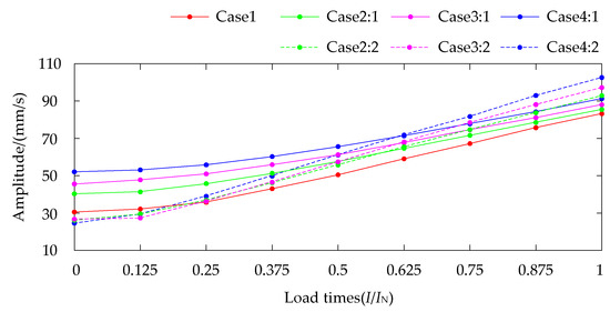
Figure 8.
The velocity of stator vibration with load times.
Four curves with the different colors are used to represent four cases of small teeth width. Solid lines are used to represent the radial electromagnetic force on big teeth alone and the discontinuous curves are used to represent the radial electromagnetic force on big and small teeth together. Comparing the curves of Cases 2–4 in Figure 8, the velocity difference curve of stator vibration with load times can be obtained, as shown in Figure 9.
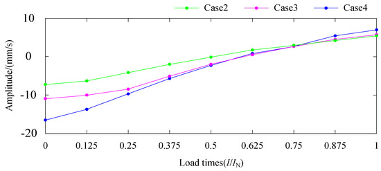
Figure 9.
The velocity difference of stator vibration with load times.
Comparing the curves of the solid and discontinuous lines in Figure 8 and Figure 9, it can be found that with the larger width of the small teeth, the amplitude of vibration velocity caused by the radial electromagnetic force acting on big teeth alone increases and correspond to the increasing of (l = 2, 10) when the radial electromagnetic force on the big teeth work only.
When the load times are small, the amplitude of vibration velocity produced by the radial electromagnetic force acting on big and small teeth together is smaller than that on big teeth alone, and the larger the width of the small teeth, the larger the velocity difference.
When the load time is equal to 1, the amplitude of vibration velocity caused by the radial electromagnetic force acting on big and small teeth is bigger than that on big teeth alone, and the larger the width of the small teeth, the larger the velocity difference.
Under the light load, the amplitude of the 10th-order radial electromagnetic force of is much larger than the amplitude of the 2nd-order force of , so the radial electromagnetic force on the teeth is mainly of the 10th order. The radial electromagnetic force of on the small teeth reduces the amplitude of , and the larger the width of the teeth, the larger the reduction of vibration velocity.
With increasing load times, the amplitude of the 10th-order radial electromagnetic force on the teeth is almost constant, and the amplitude of the 2nd-order radial electromagnetic force gradually increases.
When the load time is nearly 1, the amplitude of the 2nd-order radial electromagnetic force of is bigger, so the amplitude of the vibration velocity produced by the radial electromagnetic force on the big and small teeth together is bigger than that on the big teeth only. The radial electromagnetic force of on the small teeth increases the amplitude of, and the larger the width of the teeth tip, the larger the increase of velocity.
As shown in Figure 8, the amplitude of vibration is largest at the rated load when the load times is from 0 to 1. Hence, in order to ensure the low vibration of the motor overall, it is necessary to guarantee that at a rated load.
6. Conclusions
Through theoretical derivation and simulation analysis, the main conclusions regarding the stator with different widths of small teeth are as follows:
- (1)
- The coefficient amplitudes obtained by Fourier expansion of the radial electromagnetic force are different. The radial electromagnetic force with a lower order and bigger amplitude will produce a higher amplitude of vibration.
- (2)
- For , when l = 2, the radial electromagnetic force on small teeth increases the amplitude of , and the larger the small teeth width, the larger the amplitude of . When l = 10, the radial electromagnetic force on small teeth decreases the amplitude of , and the larger the small teeth width, the smaller the amplitude of .
- (3)
- The small teeth have a weak effect on the resonant frequencies in the same mode shapes.
- (4)
- The amplitude of vibration velocity caused by the radial electromagnetic force acting on big and small teeth together is smaller than that on big teeth alone when the load times are small, and the larger the width of the small teeth, the larger the velocity difference. When the load times is equal to 1, the amplitude of vibration velocity caused by the radial electromagnetic force acting on big and small teeth together is bigger than that on big teeth alone, and the larger the width of the small teeth, the larger the velocity difference.
When vibration and noise requirements are strict, for example, for underwater military vehicles, the drive of that needs to be as low as possible when running. Based on the above conclusions about DRPMSM, the minimum width of the small teeth should be chosen to obtain the minimum vibration velocity at a rated load to ensure its mechanical strength and electromagnetic function.
Author Contributions
All the authors have contributed significantly. Y.C. and Y.Y. put forward the idea and theoretical verification. Y.S. and Y.Y. built mathematical models and performed the simulation. Y.C. and Y.Y. analyzed the simulation results. Y.Y. made all graphics and wrote the paper.
Funding
This research was funded by the National Natural Science Foundation of China (No. 51377114).
Conflicts of Interest
The authors declare no conflict of interest.
References
- Shen, J.X.; Tseng, K.J.; Vilathgamuwa, D.M.; Chan, W.K. A novel compact PMSM with magnetic bearing for artificial heart application. IEEE Trans. Ind. Electron. 2000, 36, 1061–1068. [Google Scholar]
- Bae, B.H.; Sul, S.K.; Kwon, J.H. Implementation of sensorless vector control for super-high speed PMSM of turbo-compressor. IEEE Trans. Ind. Electron. 2003, 39, 1203–1209. [Google Scholar]
- Nedic, V.; Lipo, T.A. Low-cost current-fed PMSM drive system with sinusoidal input currents. IEEE Trans. Ind. Electron. 2006, 42, 753–762. [Google Scholar]
- Raggl, K.; Warberger, B.; Nussbaumer, T.; Burger, S.; Kolar, J.W. Robust angle-sensorless control of a PMSM bearingless pump. IEEE Trans. Ind. Electron. 2009, 56, 2076–2085. [Google Scholar] [CrossRef]
- Raute, R.; Caruana, C.; Staines, C.S.; Cilia, J.; Sumner, M.; Asher, G.M. Analysis and compensation of inverter nonlinearity effect on a sensorless PMSM drive at very low and zero speed operation. IEEE Trans. Ind. Electron. 2010, 57, 4065–4074. [Google Scholar] [CrossRef]
- Zheng, P.; Wu, F.; Sui, Y.; Wang, P.; Lei, Y.; Wang, H. Harmonic analysis and fault-tolerant capability of a semi-12-phase permanent-magnet synchronous machine used for EVs. Energies 2012, 5, 3586–3607. [Google Scholar] [CrossRef]
- Kommuri, S.K.; Defoort, M.; Karimi, H.R.; Veluvolu, K.C. A robust observer-based sensor fault-tolerant control for PMSM in electric vehicles. IEEE Trans. Ind. Electron. 2016, 63, 7671–7681. [Google Scholar] [CrossRef]
- Yousefi, B.; Soleymani, S.; Mozafari, B.; Gholamian, S.A. Speed control of matrix converter-fed five-phase permanent magnet synchronous motors under unbalanced voltages. Energies 2017, 10, 1509. [Google Scholar] [CrossRef]
- Brando, G.; Piegari, L.; Spina, I. Simplified optimum control method for mono-inverter dual parallel PMSM drive. IEEE Trans. Ind. Electron. 2017, 65, 3763–3771. [Google Scholar] [CrossRef]
- Donato, G.D.; Scelba, G.; Pulvirenti, M.; Scarcella, G.; Capponi, F.G. Low-t, high-resolution, fault-robust position and speed estimation for PMSM drives operating in safety-critical systems. IEEE Trans. Power Electron. 2018. [Google Scholar] [CrossRef]
- Chen, Y.G.; Zhai, W.C.; Shen, Y.H. Analysis on temperature field distribution of dual-redundancy PMSM. J. Tianjin Univ. 2015, 48, 488–493. [Google Scholar]
- Chen, Y.G.; Zhang, B. Minimization of the electromagnetic torque ripple caused by the coils inter-turn short circuit fault in dual-redundancy permanent magnet synchronous motors. Energies 2017, 10, 1798. [Google Scholar] [CrossRef]
- Chen, Y.G.; Chen, X.M.; Shen, Y.H. On-line detection of coil inter-turn short circuit faults in dual-redundancy permanent magnet synchronous motors. Energies 2018, 11, 662. [Google Scholar] [CrossRef]
- Jang, G.H.; Lieu, D.K. The effect of magnet geometry on electric motor vibration. IEEE Trans. Magn. 2002, 27, 5202–5204. [Google Scholar] [CrossRef]
- Benbouzid, M.E.H.; Reyne, G.; Derou, S.; Foggia, A. Finite element modeling of a synchronous machine: Electromagnetic forces and modes shapes. IEEE Trans. Magn. 1993, 29, 2014–2018. [Google Scholar] [CrossRef]
- Taegen, F.; Kolbe, J.; Verma, S.P. Vibrations and noise produced by special purpose permanent-magnet synchronous motors in variable frequency operation. In Proceedings of the 2001 IEEE International Conference on Power Electronics and Drive Systems (PEDS), Denpasar, Indonesia, 25 October 2001; pp. 583–588. [Google Scholar]
- Yu, S.B.; Tang, R.Y. Electromagnetic and mechanical characterizations of noise and vibration in permanent magnet synchronous machines. IEEE Trans. Magn. 2006, 42, 1335–1338. [Google Scholar]
- Chen, Y.S.; Zhu, Z.Q.; Howe, D. Vibration of PM brushless machines having a fractional number of slots per pole. IEEE Trans. Magn. 2006, 42, 3395–3397. [Google Scholar] [CrossRef]
- Islam, R.; Husain, I. Analytical model for predicting noise and vibration in permanent-magnet synchronous motors. IEEE Trans. Ind. Appl. 2010, 46, 2346–2354. [Google Scholar] [CrossRef]
- Sun, T.; Kim, J.M.; Lee, G.H.; Hong, J.P.; Choi, M.R. Effect of pole and slot combination on noise and vibration in permanent magnet synchronous motor. IEEE Trans. Magn. 2011, 47, 1038–1041. [Google Scholar] [CrossRef]
- Zhu, Z.Q.; Xia, Z.P.; Wu, L.J.; Jewell, G.W. Influence of slot and pole number combination on radial force and vibration modes in fractional slot PM brushless machines having single- and double-layer windings. In Proceedings of the 2009 IEEE Energy Conversion Congress and Exposition, San Jose, CA, USA, 20–24 September 2009; pp. 3443–3450. [Google Scholar]
- Islam, M.S.; Islam, R.; Sebastian, T. Noise and vibration characteristics of permanent-magnet synchronous motors using electromagnetic and structural analyses. IEEE Trans. Ind. Appl. 2011, 50, 3214–3222. [Google Scholar] [CrossRef]
- Yang, H.D.; Chen, Y.S. Influence of radial force harmonics with low mode number on electromagnetic vibration of PMSM. IEEE Trans. Energy Convers. 2014, 29, 38–45. [Google Scholar] [CrossRef]
- Li, D.B.; Lu, X.H. Analysis and Application of Vibration Mode, 1st ed.; Space Navigation Press: Beijing, China, 1989; pp. 16–19. ISBN 9787800342493. [Google Scholar]
© 2018 by the authors. Licensee MDPI, Basel, Switzerland. This article is an open access article distributed under the terms and conditions of the Creative Commons Attribution (CC BY) license (http://creativecommons.org/licenses/by/4.0/).