Article

Conceptual Synthesis of Speed Increasers for Wind Turbine Conversion Systems

1
Design of Mechanical Elements and Systems R&D Centre, Transilvania University of Brasov, Brasov 500036, Romania
2
Renewable Energy Systems and Recycling R&D Centre, Transilvania University of Brasov, Brasov 500036, Romania
*
Author to whom correspondence should be addressed.
Energies 2018, 11(9), 2257; https://doi.org/10.3390/en11092257
Submission received: 30 June 2018 / Revised: 9 August 2018 / Accepted: 22 August 2018 / Published: 27 August 2018
(This article belongs to the Collection Wind Turbines)

Abstract

:
Most wind turbines (WT) are of the single-rotor type, which means they are simple, reliable and durable, but unlikely to convert more than 40% of the available wind energy. Different solutions are proposed to minimize WT energy loss and improve performance, such as the use of speed increasers, counter-rotating wind rotors or counter-rotating electric generators. Downsizing the design, saving weight and reducing the cost of WT conversion systems, while increasing their efficiency, have posed constant challenges to WT designers. Nevertheless, very little research in the field is concerned with, and partially recommends, the design of conversion systems. Therefore, the aim of this paper is to propose a specific algorithm for the conceptual synthesis of speed increasers integrated in WT conversion systems, starting with an inventory of all combinations of the main components of a conversion system that prove compatible for efficient functioning. The algorithm is structured in two sections: the first one includes a four-step approach to WT system design, while the second one follows a three-step procedure for identifying the speed increaser concept. Twenty-two variants of speed increasers are further generated and analyzed, four of which are innovative solutions proposed by the authors. The paper also provides guidelines for identifying the WT conversion system concept according to the circumstances of its application.

1. Introduction

The interest in implementing renewable energy systems has grown significantly over the last few decades, mainly due to high prices of fossil fuels, their constant depletion and, most importantly, their harmful impact on the environment. Of all renewable energy sources, the use of wind power to generate electricity has spread worldwide as an affordable alternative to the existing conventional solutions. Most of the wind turbines (WT) which are currently in use are of the single-rotor type, as they are simple, reliable and durable, but they can only convert less than 40% of the available wind power into electrical energy, mainly because of viscous losses [1,2,3]. These losses are even higher in the built environment, due to the complex behavior of air flow around buildings [4,5,6]. Nowadays, different solutions are being implemented on wind turbines in order to minimize energy loss and improve their performance. For instance, single-rotor horizontal axis wind turbines (HAWT) include a yaw mechanism meant to set the turbine on the wind direction and, thus, to collect a larger amount of wind energy. Unlike HAWT, vertical axis wind turbines (VAWT) have the advantage of proper functioning in turbulent wind; therefore, they will not need a yaw mechanism, as they can be driven by air flow, irrespective of its direction. However, their main disadvantage is a lower power output as compared to HAWT, which makes them suitable particularly for small-scale and residential applications. Apart from that, the designers of wind turbines are facing problems regarding the size and weight of the conversion system and the power output it generates. Thus, an increase in wind rotor size produces higher nominal power, but the system will fail to function on lower wind speeds. On the other hand, downsizing the rotor so as to work properly on low wind speeds involves a reduction in power output.
To surmount the typical incongruence between the wind rotor, which operates efficiently at relatively low rotational speeds, and the electric generator, which has an optimal functioning at higher speeds, a gearbox has to be used as a speed increaser, so as to provide a compatible connection between the wind rotor and the electric generator. Therefore, gaining a reduction in losses, weight and cost, which may lead to an increase in the power coefficient (i.e., the efficiency of a WT conversion system), has always been a challenge in designing wind turbine conversion systems.
Different approaches aimed at improving WT performance have been proposed in the specialist literature, the vast majority tackling issues such as the number or shape of rotors/blades, or the gearbox [1,3,6,7,8,9,10,11]. The gear contact fatigue analysis under dynamic conditions, considering typical loads on WT gearboxes, is presented in [12]. A solution whose application is gaining ground in the market resides in wind turbines containing two coaxial counter-rotating rotors, which are able to increase conversion efficiency up to 64% during the steady state regime, as compared to single-rotor wind turbines, and can generate up to 1 MW of electrical energy [1,2,3,7,10,11,13,14,15,16]. Yet, during the transient regimes, the dynamic behavior of counter-rotating turbines depends on the number, type and arrangement of their components [14]. Unlike single-rotor wind turbines, counter-rotating turbines do not need a yaw mechanism to align them with the air flow direction. Rotors can be placed on the same side of the tower or on opposite sides. In the first case, the angle of the front rotor blades has to be carefully determined so as to avoid hitting the rear rotor. In the second case, the rear rotor is smaller than the front one, which permits the generator to be fitted inside the tower so as to reduce the nacelle weight and, as a result, to allow free yawing [15]. Moreover, the torques generated by the two wind rotors are counter-balanced, thus reducing the bending stress on the tower. The speed values of the rotors are automatically adjusted to the wind characteristics [3,17]. The numerical investigation of the aerodynamic performances of a counter-rotating wind turbine with horizontal axis, in comparison with a classical HAWT, is presented in [18], and the optimal design of counter-rotating wind turbines is approached in [19].
In regard to the gearbox for WT conversion systems, several types of speed increasers are presented in the literature: spur or bevel gear trains [6,20,21], planetary gear train or combined solutions [16,22,23,24,25,26,27,28,29,30,31,32,33], variable-ratio gearboxes [34] and a hybrid transmission including a planetary gear train and a control system, designed for a variable-speed WT [35]. The dynamic behavior of a combined planetary and spur gear type speed increaser under different internal and external excitations, based on a four degrees of freedom (DOF) dynamic model, is presented in [36]. An example of the synthesis of speed increasers with one input and one output, where 16 reference solution types are obtained, is proposed in [37].
One recent solution features a wind turbine with higher output speed and compact design which includes a counter-rotating electric generator (i.e., the inner and the outer armatures rotate in opposite directions) [1,25,38]. However, this type of WT has a relatively low capacity and, therefore, it is mainly implemented in urban environments. The optimal operation of the electric generators implemented in WT for improving the transient stability by using different modern hybrid control techniques is presented in [39,40].
Although most research in the field either discusses the effects of design parameters on the aerodynamic performances of a wind turbine and its power output or draws comparisons between different types of systems in terms of energy production, only a few papers partially favor the WT conversion system design [5,30,34,35].
Starting from and refining the core concepts developed in the literature, this paper aims to develop a specific algorithm tailored for the conceptual design of speed increasers for wind turbine systems as a useful tool in the design process of a large class of wind turbines: with one or two wind rotors, with a classical or counter-rotating electric generator, and a compatible speed increaser with one or two DOF. As results, we will further describe in Section 2 an appropriate conceptual design algorithm for the development of speed increasers integrated in WTs, proposed by the authors, through a systematic approach starting with an inventory of all combinations of the main components of a conversion system (e.g., wind rotor(s)—speed increaser—electric generator) that might prove compatibility for efficient functioning, and then providing guidelines for establishing the conceptual solution in keeping with specific conditions of the application. Thus, the principles of conceptual synthesis are applied in Section 3 to generate solving variants of the global function that includes a maximum of two wind rotors, a speed increaser and an electric generator with either fixed or mobile stator, according to a previously stated list of requirements. The morphological matrix obtained on the basis of known (i.e., mentioned in the literature and proposed by the authors) structural variants that solve each sub-function of the WT global function allows us to generate a large number of different qualitative solving variants of the global function by combining different structural variants of its three main sub-functions.
Subsequently, in Section 4, the paper focuses on the conceptual design of speed increasers used in WTs. For the sake of clarity, from a larger data base of variants generated by the authors, only a limited number of 22 qualitative solving variants of the speed increasing sub-function are presented in this paper. These qualitative solving variants are classified into four categories according to the speed increaser’s number of inputs (i.e., number of wind rotors) and its complexity. Either one-output (i.e., generator with fixed stator) or two-output (i.e., electric generator with mobile stator, known as ‘counter-rotating generator’) types will be considered in a category. For each of the stated categories, one representative qualitative solving variant is identified by rough evaluation, assuming that all speed increasers are of the same radial size. The defining parameters of the representative qualitative solving variants and the analytical correlations among them are further established by means of kinematic, static and dynamic analysis based on the quantitative specifications in the requirements list. Thus, quantitative solving variants are obtained, associated with the representative qualitative solving variants previously selected. Six of them have qualified for fine evaluation, based on implementation conditions and imposed criteria, aiming to identify the conceptual solution by fine evaluation based on a specific technical criteria set. This optimal solution is the final result of the conceptual synthesis and can further go through the development process by embodiment design, virtual prototyping, detail design, prototype manufacturing, testing and optimization.
The main contribution of the paper refers to the widening of the database of speed increasers for wind turbines with novel concepts, four of which are innovative solutions patented by the authors, due to the application of the new appropriate tailored conceptual synthesis algorithm detailed in this paper.

2. Proposed Algorithm for Conceptual Synthesis of Wind Turbine Systems

The designers of wind turbine conversion systems are facing the challenge of firstly establishing an appropriate system structure complying with the initial stated requirements, considering the main WT components (wind rotor, speed increaser, and electric generator) and the links between them. In practice, mainly classical systems are developed and implemented, with one or two wind rotors, with a simple speed increaser or without one, and a classical electric generator (with fixed stator) [21,41,42]. Yet, there are other advanced solutions which have remained unexplored. For this reason, the conceptual algorithm proposed in the paper starts from the global function of wind turbine systems and exhaustively covers the WT categories with one and two wind rotors, finally offering designers guidelines for the optimal design of the speed increasing sub-function. This algorithm, depicted in Figure 1, is divided into two major sections: the first four steps refer to WT system conceptual design (Section 3), which aims to identify the conditions and requirements for the conceptual synthesis of the speed increaser—Steps 5–7, detailed in Section 4. The sub-functions of converting wind energy into mechanical energy and, subsequently, into electric energy are addressed in the paper only in terms of setting the inputs and outputs of the speed increasing sub-function. In the general case of the conceptual synthesis of the entire wind turbine system, the second section of the algorithm can be applied, with specific peculiarities, for the other two sub-functions of the global function, i.e., conversion of the wind energy into mechanical energy and of the mechanical energy into electricity, respectively.
The goal of a system conceptual synthesis consists of identifying its conceptual solution, illustrated through an optimal conceptual scheme, for certain imposed requirements. Usually, the synthesis process is corroborated with the analysis of system operating conditions. Several models for the conceptual synthesis are proposed in the specialist literature [43,44,45,46,47]. These design models are formulated in different ways, but they basically lead to the same product development algorithm, of the type: global problem—sub-problems—sub-solutions—global solution. The algorithm used in this paper for the conceptual synthesis of an optimal WT conversion system is developed by the authors [47,48] based on the German VDI (Verein Deutscher Ingenieure) model [46]. This algorithm consists of the following steps (Figure 1), detailed in Section 3 and Section 4:
  • Statement of the system global function according to the requirements, by defining the correlations between its input and output entities of material, energy and information types. Only the simplified case in which the WT global function is reduced to the energy flow (the main flow) is considered in this paper; the other two secondary flows (of material and information type) are ignored as they have insignificant relevance for the paper subject. The requirements list is defined by a specialized team according to the customer needs and represents the input in the conceptual design process. The requirements are stated in terms of qualitative and quantitative specifications (of structural, geometric, kinematic, static, dynamic and other types), as well as a set of technical and economic criteria used to evaluate the resulting variants.
  • Description of the sub-functions structure of the global function based on the structural specifications in the requirements list, i.e., defining the component sub-functions (either elementary or composite) and the relationships established between them. In the structure of WT global function, three main sub-functions are considered relevant in this study: the conversion of wind energy into mechanical energy, followed by the change of the mechanical energy state parameters (speed and torque) and, finally, the conversion of mechanical energy into electricity.
  • Identification of known structural variants that solve each sub-function and generation of qualitative solving variants of the global function as compatible combinations of the structural variants for all sub-functions by means of morphological matrix. A structural variant is the qualitative (conceptual) solution of a function, defined as a solving principle by a physical effect implemented by an effect carrier, and its configuration [45,47] (e.g., the one DOF helical planetary gear with one input and one output can be used as a structural variant of the speed increasing sub-function).
  • Classification of the obtained qualitative solving variants into categories according to specific features of the main sub-functions, such as the number of wind rotors, speed increaser complexity and electric generator type. A qualitative solving variant of the WT system is composed by the set of structural variants, one for each of the three main sub-functions stated before, compatible between them; since dimensions or other quantitative aspects are not involved at this stage, the solving variants are of “qualitative” type. The obtained WT solving variants are classified into different categories according to the number of inputs and outputs of the speed increaser.
  • Selection of the representative qualitative solving variant for each category by rough evaluation, using specific criteria defined in the requirements list. Steps 5–7 apply in this algorithm only for the sub-function of mechanical energy state parameters modification, considered further as “global function” of the speed increaser. The 22 proposed structural solutions of speed increaser are classified into four categories and the best (representative) solution is identified based on a specific set of evaluation criteria.
  • Establishment of quantitative solving variants of the global function by kinematic, static and dynamic analysis of the representative qualitative solving variants. The variants that do not quantitatively meet all the requirements are eliminated. The representative qualitative solutions of speed increaser that were previously identified are quantitatively designed in terms of number of teeth and transmission efficiency.
  • Selection of the optimal solution (the conceptual solution) by fine evaluation based on a set of criteria also stated in the requirements list. The fine evaluation uses different weight coefficients for the considered evaluation criteria, established in this paper through the Frisco method.
This algorithm is further applied to generate the optimal solution of WT conversion systems for certain implementation conditions.

3. Conceptual Synthesis at Wind Turbine System Level

3.1. Sub-Functions Structure of the Wind Turbine Global Function

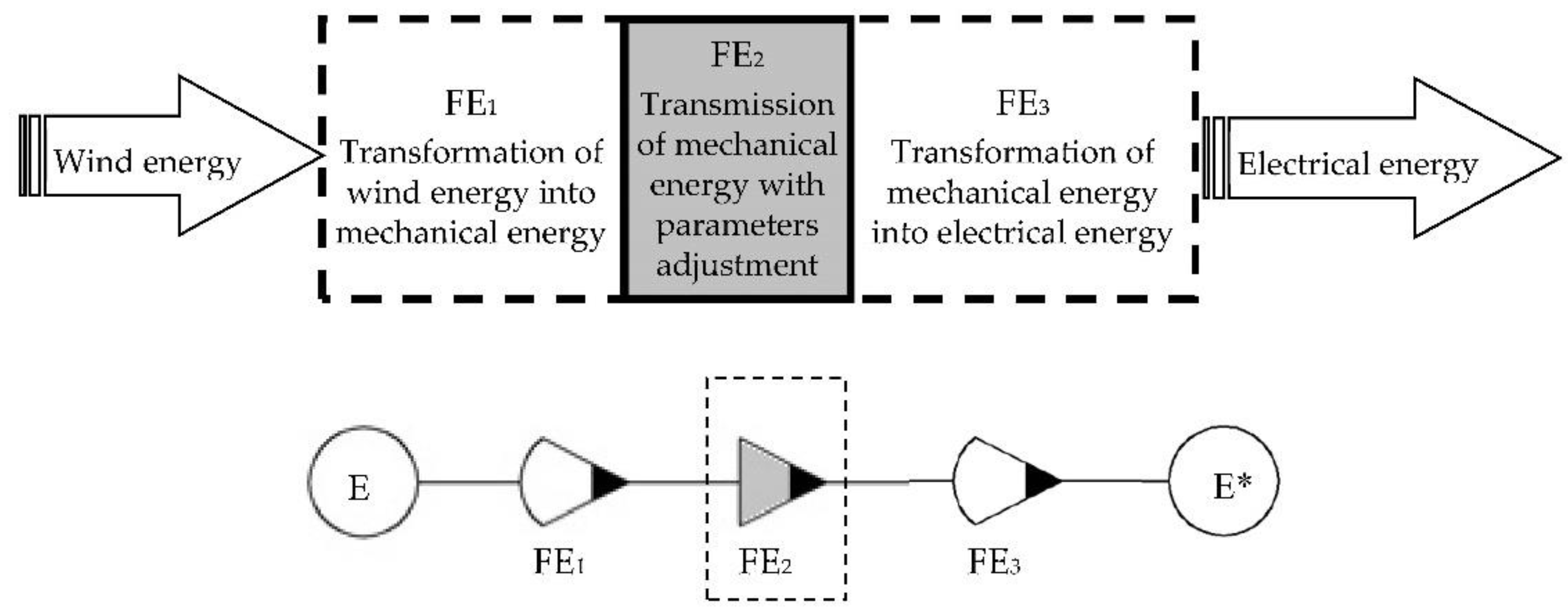
The WT global function—the conversion of the wind energy into electrical energy through mechanical motion (Figure 1—Step 1)—has a simplified sub-function structure (Figure 1—Step 2) as depicted in Figure 2, considering only the main flow of the energy conversion. The input and output in the energy flow are denoted in Figure 2 by E (wind energy) and E* (electric energy), respectively. Other sub-functions usually included in the global function of WT conversion systems, such as information or material flow sub-functions (e.g., the monitoring and control system or the yaw drive system), are not considered in this study. The graphical representation of the WT global function is performed with specific VDI symbols [46], whose meaning is defined in the legend of Figure 2. The FE2 sub-function represents this paper’s focus and is highlighted in Figure 2 to better emphasize its direct links with the other two sub-functions (FE1 and FE3) of the WT global function.

3.2. Morphological Matrix

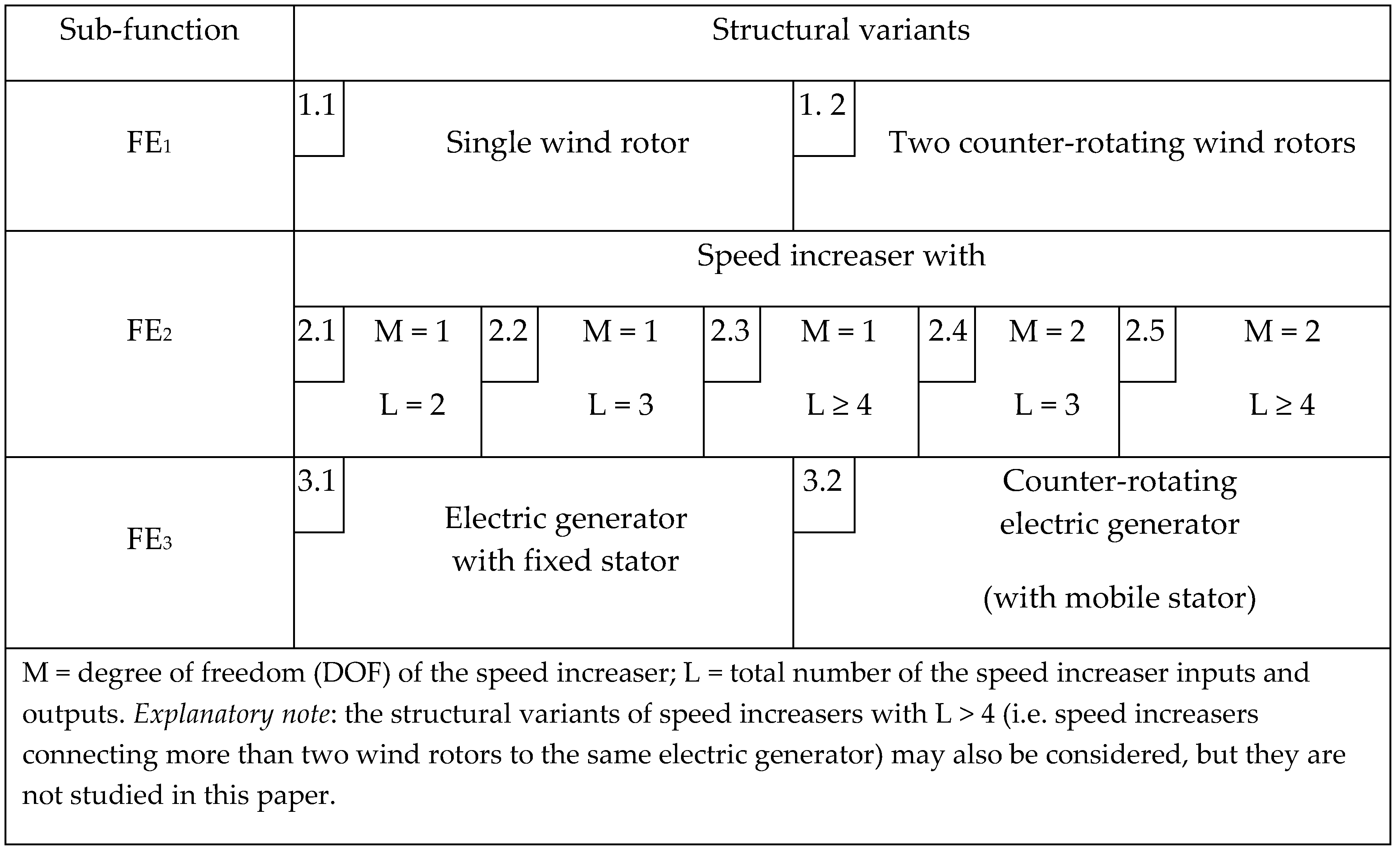
The three sub-functions of a WT global function can be fulfilled by different structural variants, systematized in the morphological matrix in Figure 3, in line with Figure 1—Steps 2 and 3. Two structural variants for each transformation sub-function and five structural variants for the second sub-function are included in this matrix. Some of these structural variants have been identified in the literature [21,31,33,42,49,50,51,52,53,54], and others are pending patents proposed by the authors (solutions of 2.2, 2.3 and 2.5 type [55,56,57,58], Figure 3). Furthermore, the qualitative solving variants of the conversion system are generated by means of a compatible combination of the structural variants included in the morphological matrix, which are classified into several categories according to a set of specific criteria (as detailed in Section 4), Figure 1—Step 4.

3.3. Categories of Qualitative Solving Variants of the Global Function

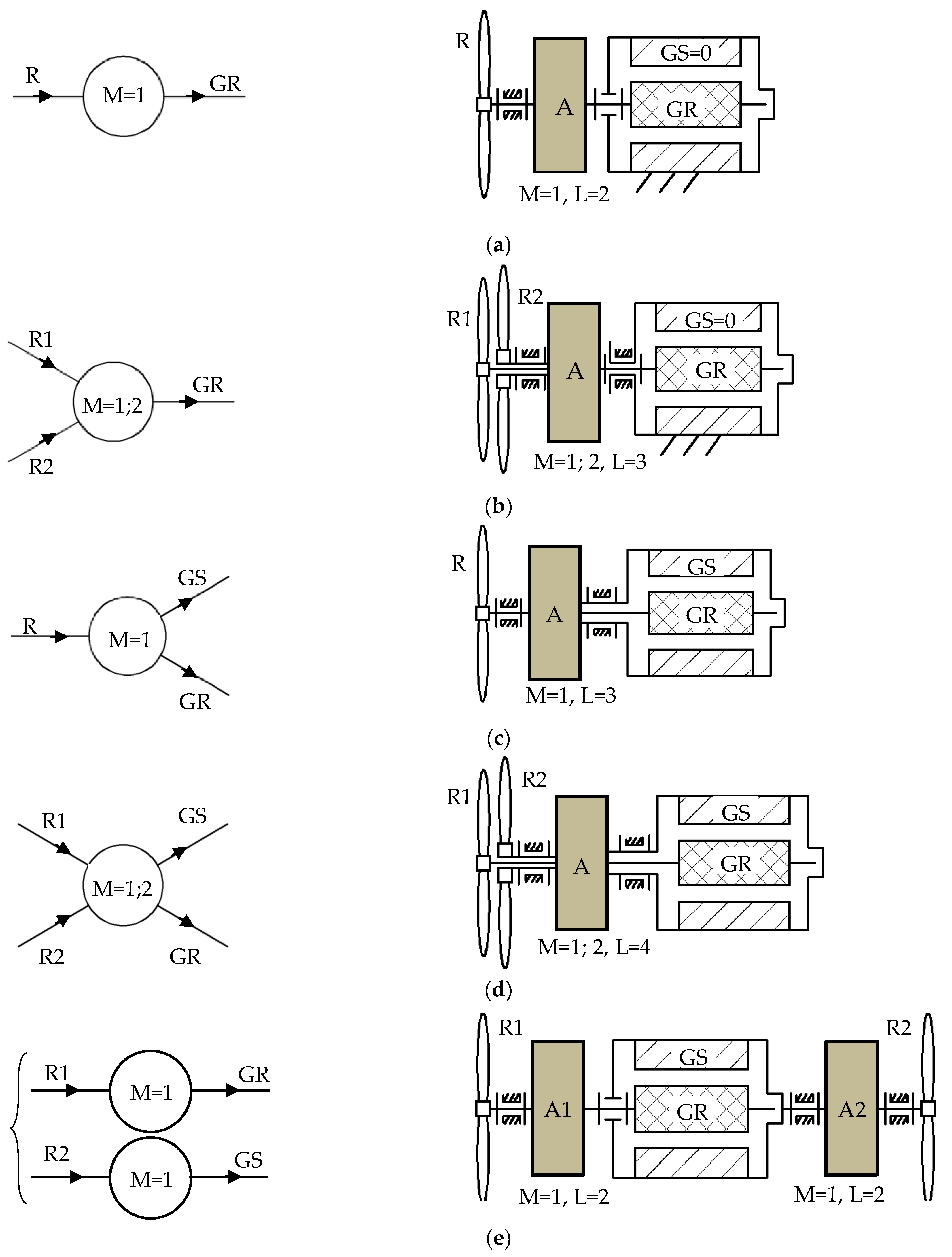
The structural variants of the speed increaser, associated with the FE2 sub-function—Figure 2, are in direct correlation with the structural variants of the wind rotor (sub-function FE1) and electric generator (sub-function FE3). The WT speed increaser configurations, with DOF of the speed increaser (M) = 1 or 2 and the total number of the speed increaser inputs and outputs (L) = 2; 3; 4, are generated by a compatible combination of inputs (i.e., the outputs of the FE1Figure 2) and their outputs (i.e., the inputs of the FE3Figure 2). Thus, the compatible combinations for generating the speed increaser configurations with L ≤ 4, according to the morphological matrix in Figure 3, are systematized in Figure 4.
The typical WT conversion systems comply with one of the following conceptual schemes (Figure 5):
  • The WT uses an electric generator with fixed stator (generator stator (GS) = 0) that is driven by one of the following solutions, Figure 5a,b:
    (a)
    the wind rotor (R) is connected to the generator rotor (GR) through a one degree of freedom (one DOF) speed increaser, A (Figure 5a) [5,25,49].
    (b)
    two counter-rotating wind rotors, R1 and R2, are connected to the generator rotor, GR, through a one DOF [50] or a two DOF [16,23,26,29,30,31,32,51] speed increaser, A (Figure 5b). R1 is considered the main rotor, always interconnected with the GR. In the first case (M = 1), R2 provides an additional input torque, while in the second case (M = 2), R2 contributes to increasing the output speed.
  • The WT uses a counter-rotating electric generator (both GR and GS are mobile and rotate in opposite directions), Figure 5c–e:
    (a)
    R is connected to a one DOF speed increaser, A, with two outputs: one for the GR, and the other for the GS (Figure 5c) [25,52].
    (b)
    R1 and R2 are connected through a one DOF or two DOF speed increaser, A, with two outputs to the GR and GS (Figure 5d) [24,26,27,28,53,54].
    (c)
    R1 is connected to the GR through a speed increaser, A1, and R2 is connected to the GS through another speed increaser, A2 (Figure 5e) [33].
In the configurations presented in Figure 5, a WT conversion system can contain:
(1)
one or two wind rotors.
(2)
one DOF speed increasers with one input and one output (L = 2) or two outputs (L = 3, where L is the number of inputs and outputs) or two inputs (L = 3—one output, L = 4—two outputs), and/or two DOF speed increasers with one output (L = 3) or two outputs (L = 4).
(3)
an electric generator with fixed or mobile stator.
The analysis of the previous configurations, Figure 5, can lead us to the following remarks:
  • the conversion systems without a speed increaser usually have a reduced capacity as the wind rotor speed must be compatible with the generator speed (which has a special construction that allows lower operating speeds than usual, and low electric power, implicitly).
  • the gearbox (speed increaser) size and complexity increase with the multiplication ratio and power increase.
  • the use of two counter-rotating wind rotors allows higher output power at the generator, either by summing up the input motions in the case of two DOF speed increasers or by summing up the torques in the case of one DOF speed increasers.
  • the systems using counter-rotating generators (where both rotor and stator are mobile) allow either the reduction of the multiplication ratio or a decrease in the rotor(s) input speed(s).
  • the use of a multi-stage gearbox with a high-speed generator increases both complexity and cost of the conversion system, but the system is compact for higher multiplication ratios, whereas the use of a single-stage transmission reduces complexity, but the size and weight of the conversion system increases with the multiplication ratio.

4. Conceptual Synthesis of Speed Increasers for Wind Turbines

The conceptual design process of speed increasers for WTs starts from the requirements of the WT conversion system and its components. Based on the critical analysis of the solutions presented in the literature, the main requirements refer to:
  • Structural specifications:
    -
    number of wind rotors: one or two.
    -
    simple or complex gear transmission as a speed increaser; a simple transmission contains one satellite carrier, while the complex transmission has at least two distinct carriers.
    -
    electric generator with fixed or mobile stator.
  • Geometric, constructive and kinematic specifications used in the rough evaluation:
    -
    the same radial size of the speed increaser in any solving variant.
    -
    lower size of the intermediary gears for a minimal inertial effect.
    -
    imposed ratio of the largest gear and smallest gear radii.
    -
    reduced structural complexity and simpler construction of the conversion system.
    -
    increased multiplication ratio of the speed increaser.
  • Kinematic, static, dynamic and constructive specifications for the selection of the concept:
    -
    imposed multiplication ratio of the speed increaser (10 ± 0.5% for the analyzed case study).
    -
    highest efficiency of the speed increaser.
    -
    highest mechanical power on the generator shaft.
    -
    smallest axial size of the speed increaser.
    -
    complexity degree of the conversion system as low as possible.
Accordingly, the global function of a WT conversion system can be stated as the conversion of the wind energy into electrical energy in the most efficient way and affordable implementation.
Furthermore, based on the main requirements, the optimal solution of a speed increaser for WT conversion systems will be selected among the variants generated within the proposed conceptual synthesis algorithm, Figure 1.

4.1. Qualitative Solving Variants for Speed Increasers

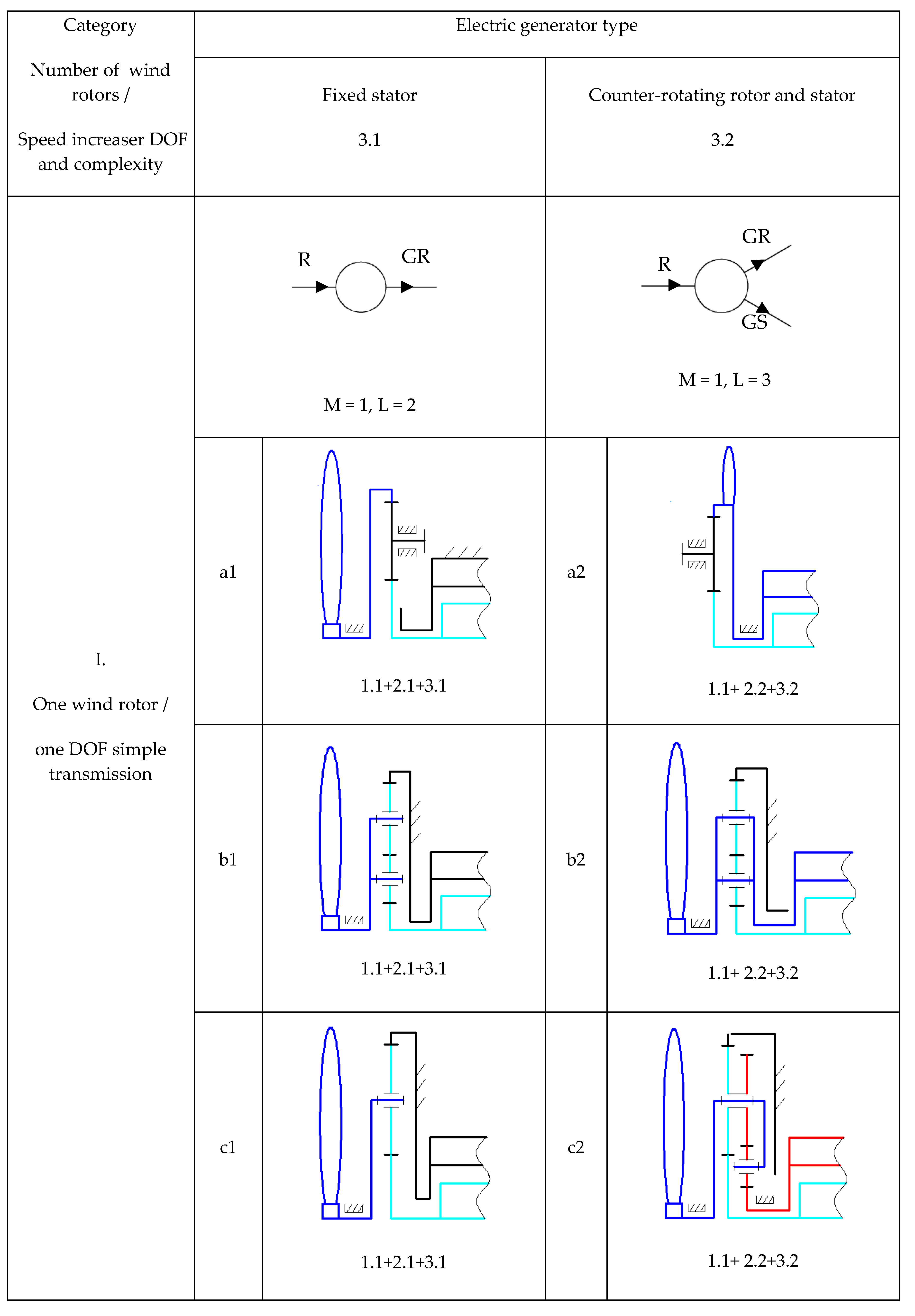
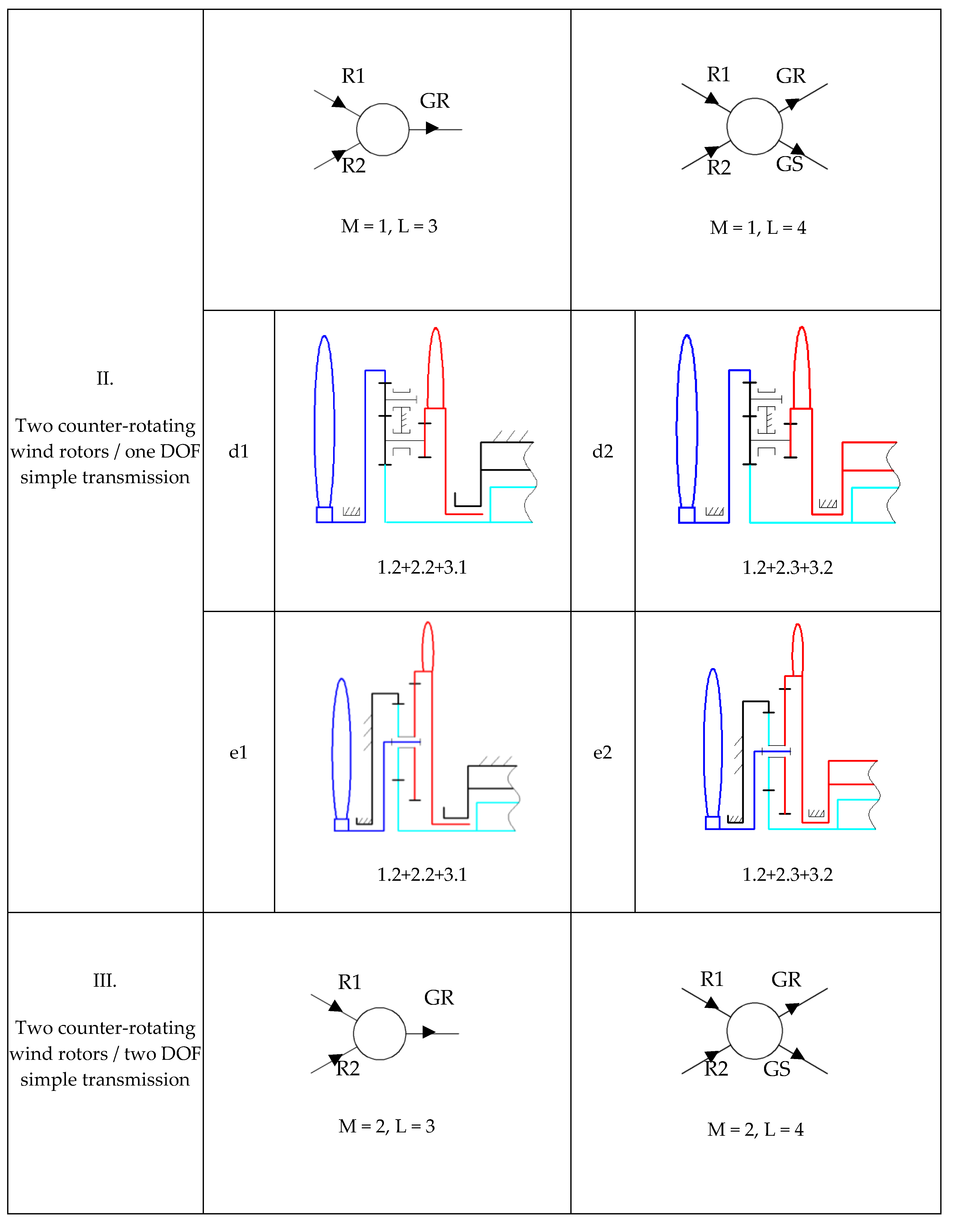
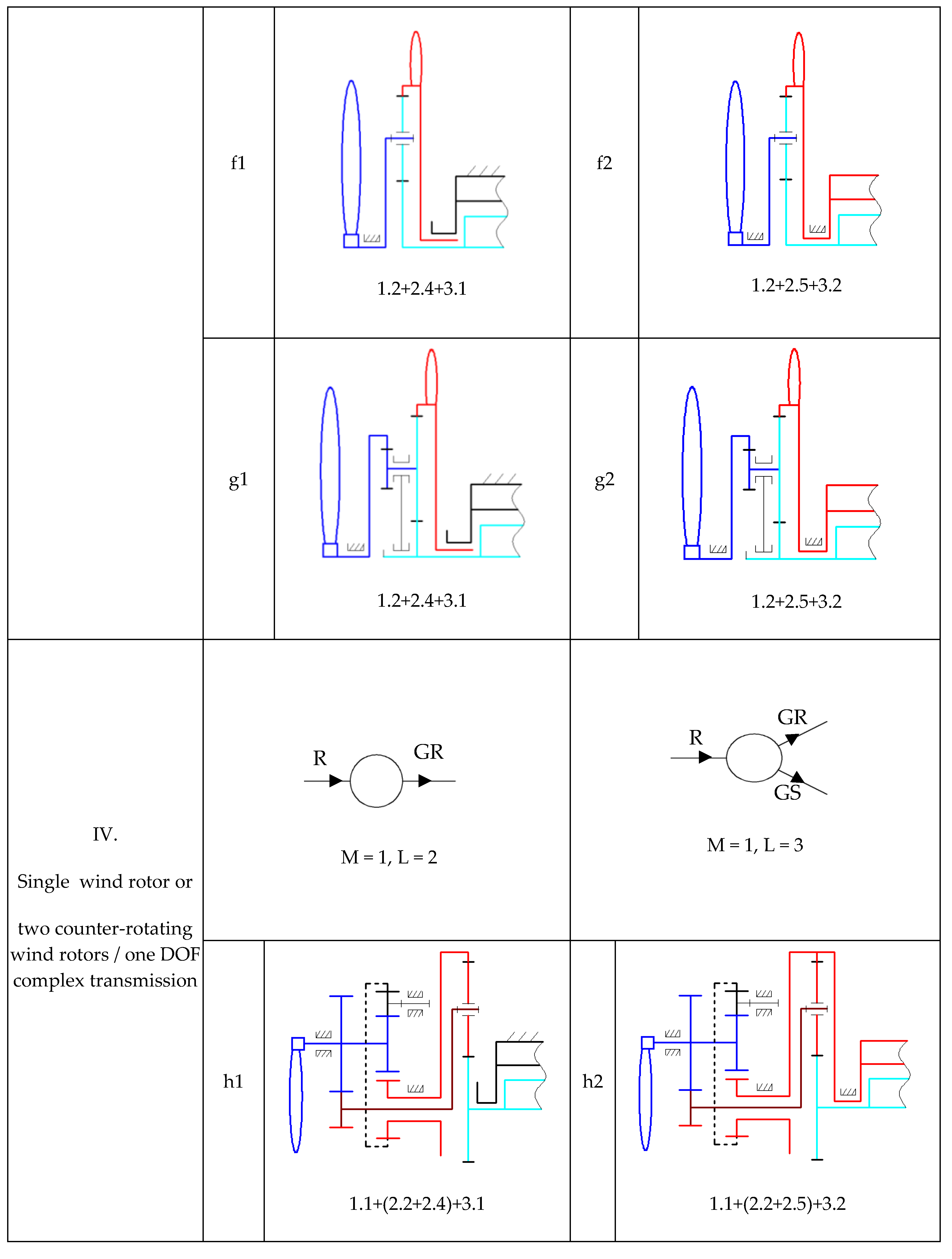
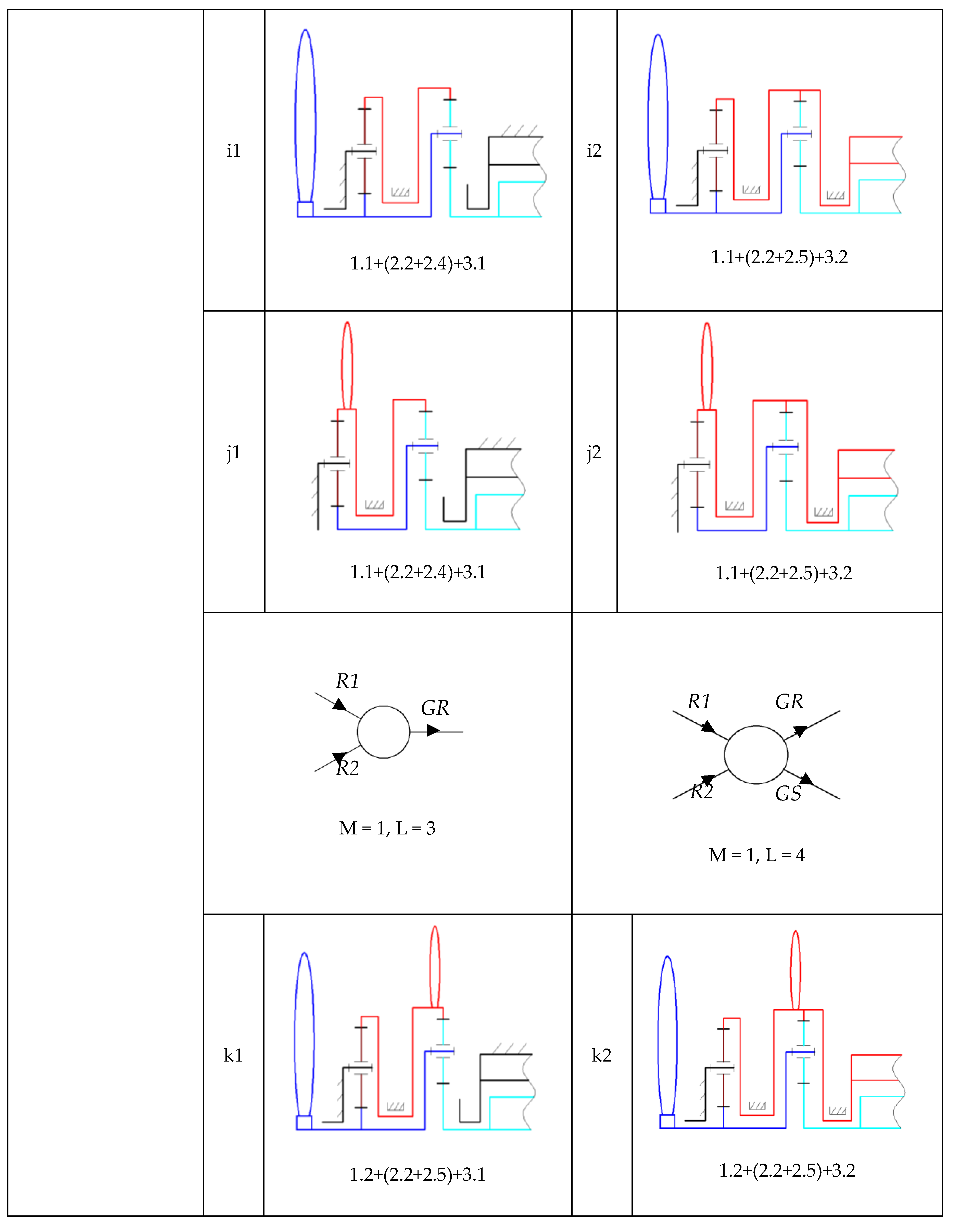
By compatible combination of the structural variants stated in Figure 3 and detailed in Figure 4 and Figure 5, 22 distinct qualitative solving variants are proposed and represented in Figure 6; as the conversion system is symmetrical with respect to the longitudinal axis, only the upper half of the structural schemes is depicted in Figure 6. The corresponding combination of structural variants from the morphological matrix (Figure 3) is indicated under each qualitative solving variant (e.g., for the a1 case from Figure 6, the qualitative solving variant is denoted by 1.1 + 2.1 + 3.1, according to structural variants numbering in Figure 3).
The qualitative solving variants are systematized into four categories (I–IV), according to Figure 1—Step 4, in terms of the number of wind rotors, speed increaser complexity, degree of freedom, and generator type (Figure 6):
  • The solutions from Figure 6a–c consist of a single wind rotor, a simple one DOF speed increaser with one input and one output (L = 2) and a low-speed generator with a fixed stator (Figure 6a1–c1) or with a mobile stator (Figure 6a2–c2).
  • The schemes from Figure 6d,e contain two statically inter-connected wind rotors, R1 and R2, a simple one DOF speed increaser with two inputs and one output (L = 3) or two outputs (L = 4) and an electric generator with a fixed (Figure 6d1,e1) or mobile (Figure 6d2,e2) stator.
  • The schemes from Figure 6f,g contain two kinematically inter-connected wind rotors, R1 and R2, a simple two DOF speed increaser with two inputs and one output (L = 3) or two outputs (L = 4) and an electric generator with a fixed (Figure 6f1,g1) or mobile (Figure 6f2,g2) stator.
  • The schemes depicted in Figure 6h–k include qualitative solving variants with single wind rotor (Figure 6h–j) or two counter-rotating wind rotors (Figure 6k), a complex one DOF transmission and classical (with fixed stator)/counter-rotating generator.
Based on the requirements imposed in the design process, the optimal variant for each of the four previously defined categories, denoted as the representative qualitative solving variant, is further identified among the qualitative solving variants in Figure 6.

4.2. Selection of the Representative Qualitative Solving Variants

The multiplication ratio of the speed increaser is further analyzed in order to simplify the selection of the representative qualitative solving variants (according to Figure 1—Step 5) and, implicitly, to search for those variants that allow the highest multiplication ratios at the same radial dimension and a reduced complexity. The comparative analysis of the resulting variants is done considering an appropriate set of assumptions. In the present study, the following qualitative and quantitative hypothesis are proposed:
  • all speed increasers have the same radial size.
  • the speed diagrams are built considering that the ratio between the largest gear radius and the smallest gear radius is equal to six.
  • the input speed is considered equal to one.
  • in the case of the solutions depicted in Figure 6f,g, the speeds of the two counter-rotating wind rotors are considered equal but in opposite directions; therefore, the ratio ( k ω ) of the input speeds is: k ω = ω R 2 / ω R 1 = 1 .
  • in the case of the solutions with counter-rotating outputs, the equivalent speed of an electric generator with fixed stator will be further used in the selection process: ω G = ω G R ω G S (i.e., the relative speed between the generator rotor and stator).
  • as the input speed is equal to one, the multiplication ratio ( i a ) of the speed increaser is given by the output speed ( ω G ), the sign “−/+” indicating that the GR is rotating in the opposite/same direction to the main rotors, R1/R.
In the previous hypotheses, the values of the multiplication ratio ( i a ) and the generator speed ( ω G ) can be obtained based on the speed diagrams, illustrated in Figure 6, Figure 7, Figure 8 and Figure 9, or analytical methods [59]. The extreme values of the variation range for the angular speed and multiplication ratio, presented in Table 1 (min/max indicates the minimum/maximum values), were obtained by modifying the pitch radius of each gear at a time, while keeping the pitch radius of the gear with the maximum size unchanged. The results for the qualitative solving variants that contain an electric generator with fixed stator (Figure 6a1–k1) are presented in columns eight and nine ( ω G = ω G R ), while those for the variants with counter-rotating generator (Figure 6a2–k2) in columns 10 and 11 ( ω G = ω G R ω G S ). As the input speeds are considered to be equal to one, the transmission multiplication ratio ( i a ) has the same values as the generator speed ( ω G ). The solving variants are gathered in categories (I–IV, Table 1) and the optimal variant for each category, obtained by rough evaluation, is written in bold red.
As Table 1 shows, the variants with counter-rotating generators are superior to those with a classical generator (with fixed stator) for the same type of speed increaser. A rough evaluation of the proposed solving variants from Figure 6 is carried out and the obtained results are systematized in Table 2, the evaluation being performed according to the following criteria:
  • C 1 = multiplication ratio, which must be as high as possible;
  • C 2 = the size of the intermediate gears has to be as low as possible to have a minimal inertial effect;
  • C 3 = simpler construction.
The proposed variants are evaluated by grades on a scale of 1–10 (Table 2), the representative variant of each speed increaser category being awarded on the last row with the first place.
As a result, the following conclusions can be highlighted from the results presented in Table 1 and Table 2 regarding the highest multiplication ratio for each category of speed increasers:
  • Category I—the conversion system containing a single wind rotor, a simple transmission and a generator with a fixed or mobile stator: the scheme from Figure 6b has the highest absolute value of the transmission multiplication ratio of this category for both functioning cases (fixed or mobile generator stator)—3 (L = 2)/6 (L = 3); the speed increaser can be with one or two outputs (one DOF, L = 2/one DOF, L = 3).
  • Category II—the conversion system containing two counter-rotating rotors, a one DOF simple transmission and a generator with a fixed or mobile stator: the variant illustrated in Figure 6e is the representative solution of this category; it contains a gearbox with a multiplication ratio of 3.76/6.72 and a simple construction for the two functioning cases—one DOF, L = 3 (two inputs and one output); one DOF, L = 4 (two inputs and two outputs).
  • Category III—the conversion system containing a single wind rotor, a two DOF simple transmission and a generator with a fixed or mobile stator: the variant from Figure 6g is the representative solution of the third category; the transmission allows a higher multiplication ratio of 29.87/38.89 for the two functioning situations—two DOF, L = 3 (two inputs and one output); two DOF, L = 4 (two inputs and two outputs).
  • Category IV—the conversion system containing one or two rotors, a one DOF complex transmission and a generator with a fixed or mobile stator: the scheme from Figure 6j is the representative solution in terms of multiplication ratio; the transmission is characterized by a multiplication ratio of 6.42/13.71 for the two functioning situations—one DOF, L = 2 (one input, one output) and L = 3 (one input, two outputs)/one DOF, L = 3 (two inputs, one output) and L = 4 (two inputs, two outputs).

4.3. Quantitative Solving Variants of Speed Increasers: A Case Study

4.3.1. Quantitative Evaluation of the Representative Qualitative Solving Variants

An example of the conceptual solution identification for a specific application is further presented, starting from the eight representative qualitative solving variants previously selected (one for each category, functioning either with a fixed or mobile generator stator); without reducing the algorithm generality, the numerical application is considered for a 1 kW wind turbine that has the following technical specifications:
  • the speed increaser multiplication ratio: i a = 10 ± 0.5 % ;
  • the radial dimension of the gearbox is imposed by limiting the number of teeth of the biggest gear: z max = 400 ;
  • the efficiency of a gear pair: η g = 95 % .
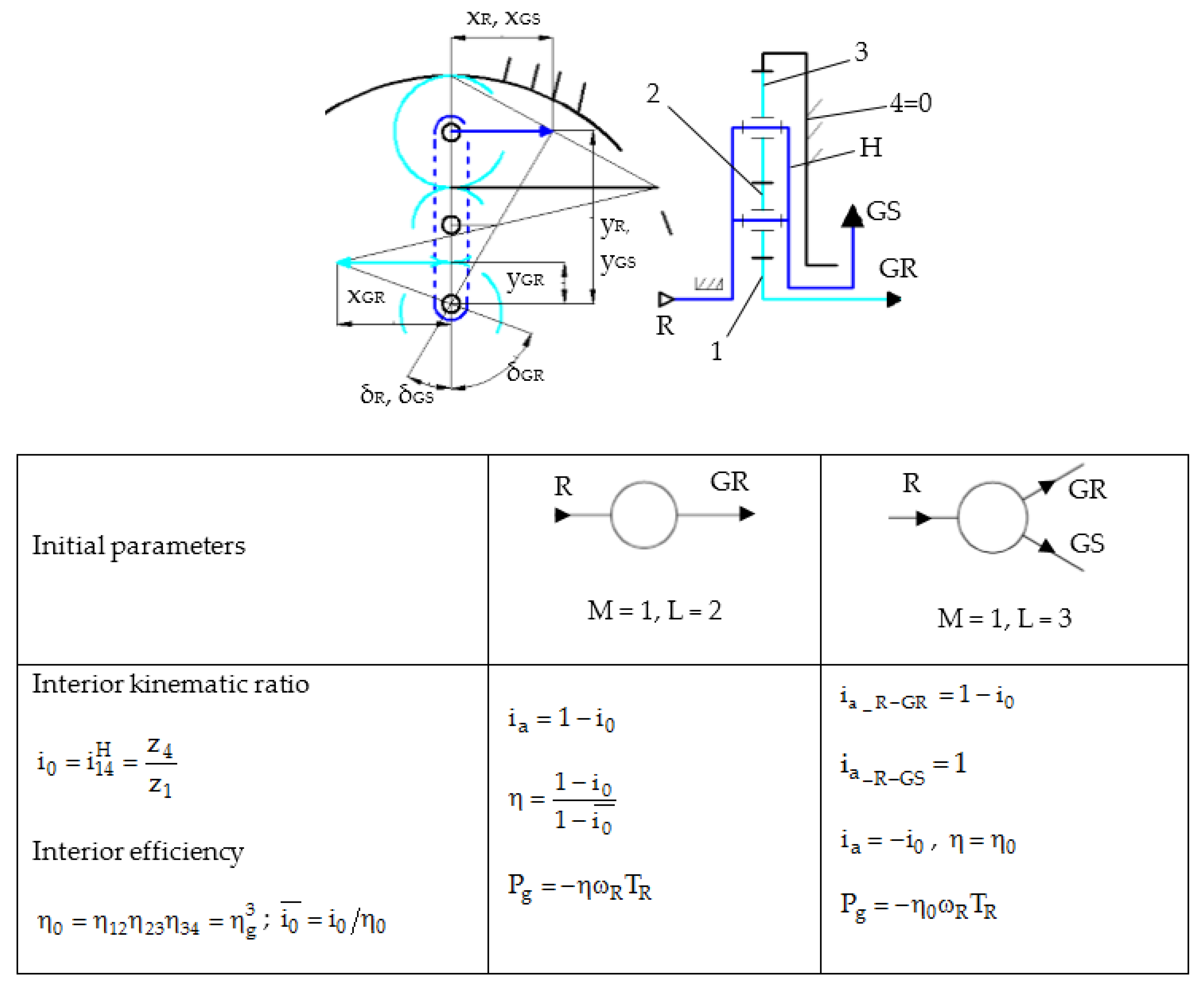
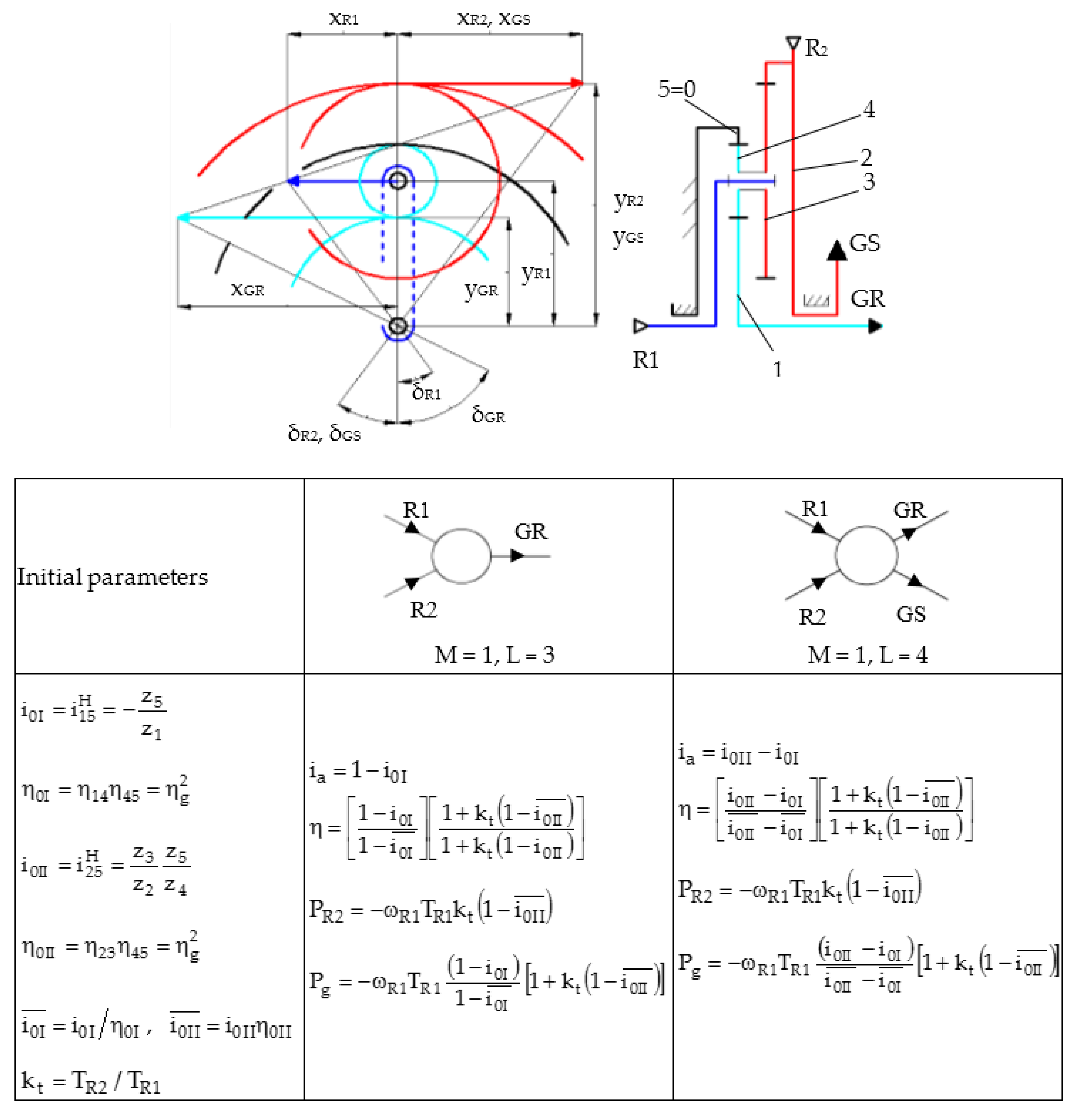
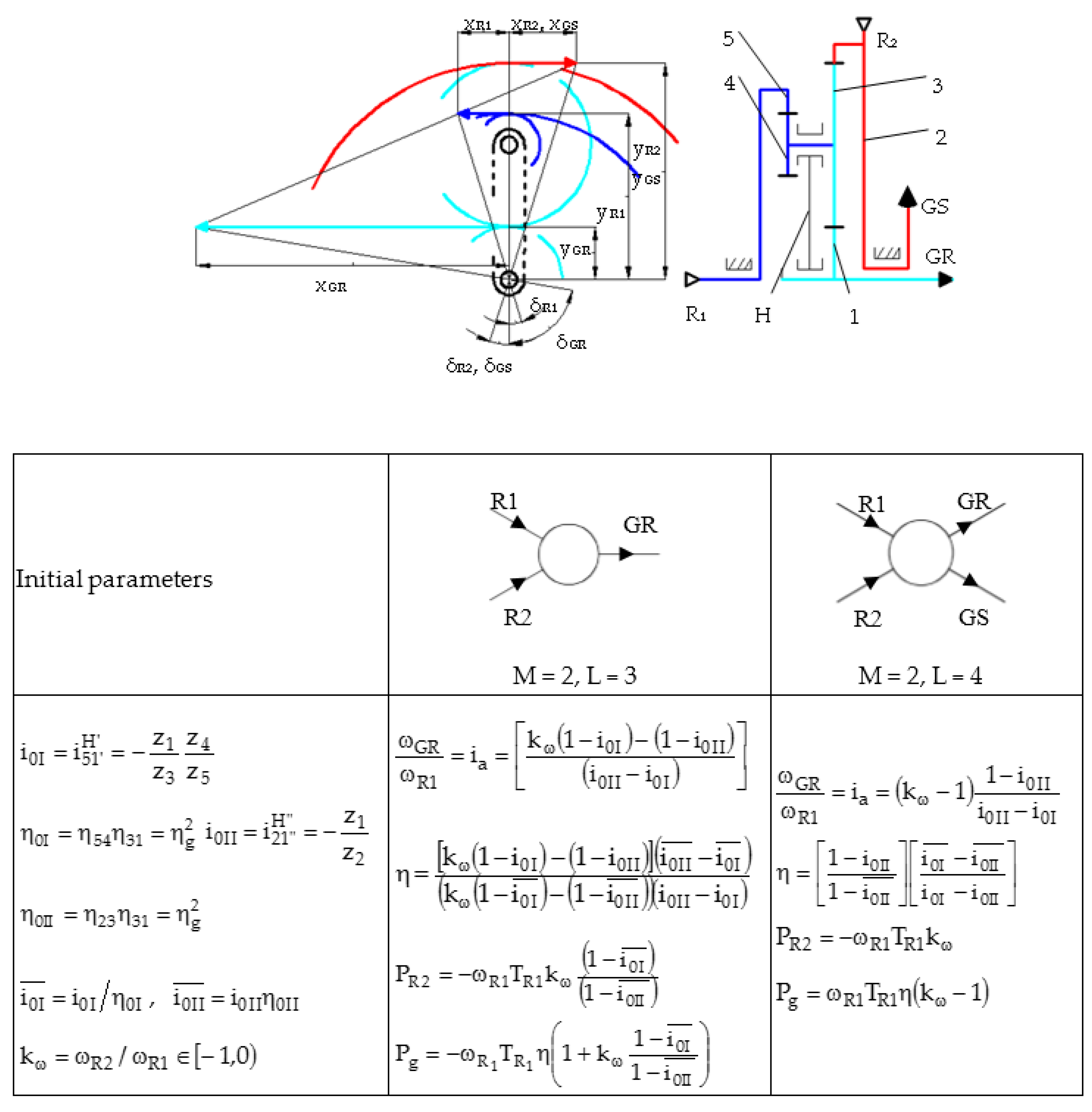
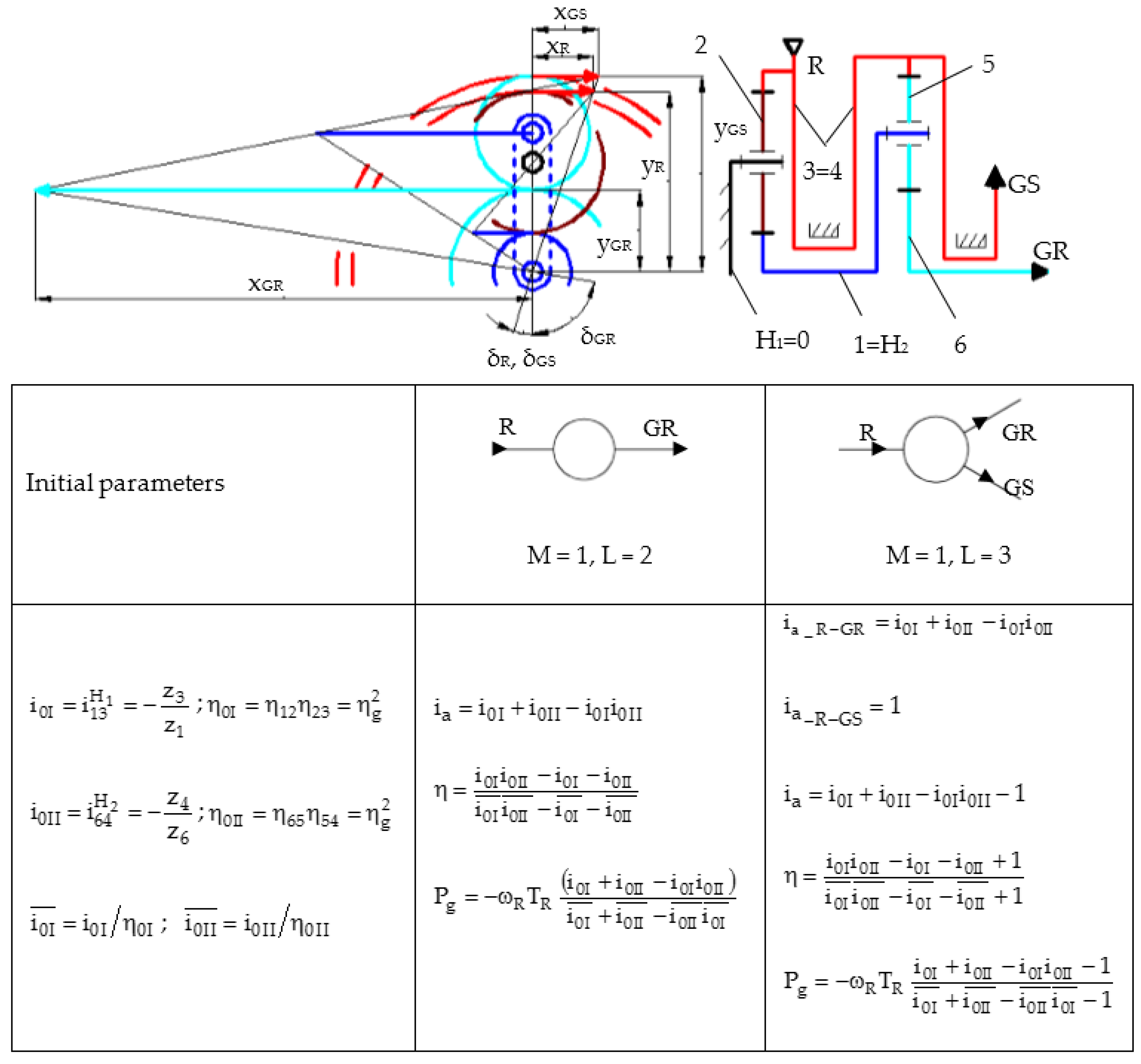
The analysis of the eight representative conversion systems is performed using the schemes from Figure 7, Figure 8, Figure 9 and Figure 10, which are derived from the afferent qualitative solving variants from Figure 6 (according to Figure 1—Step 6). The wind rotor(s) and the generator are eliminated from the structural schemes (Figure 7, Figure 8, Figure 9 and Figure 10), being replaced by the following symbols: input—connection to the wind rotor; ▶ output to the generator rotor or stator. According to the speed diagrams from Figure 7, Figure 8, Figure 9 and Figure 10 that are valid for both functioning cases (fixed or mobile stator), the angular speeds ( ω ) of the sun and ring gears, and of the planetary carrier (H) in each case are obtained from their peripheral linear speed (v) in the contact point ( v = x ) : ω = v / b = t g δ = x / y , where b = y is the distance from the contact/center point to the central (fixed) axis of rotation, δ —angles associated to the angular speed ω , defined according to Figure 7, Figure 8, Figure 9 and Figure 10 (1–6—fixed axis or planetary gears).
The relationship between the multiplication ratio ( i a ), the speed increaser efficiency ( η ) and the generator input power ( P g ) for both cases of electric generator (fixed/mobile stator) are also presented in Figure 7, Figure 8, Figure 9 and Figure 10 [23,24,25,26,27,28,29,30] for each representative solving variant, where T is the shaft torque, i 0 ¯ —interior static ratio, i a _ R G R / G S —multiplication ratio considering the GR/GS as output, i0I/II —interior kinematic ratio of the planetary gearbox I/II, η0I/II—interior efficiency of the planetary gearbox I/II, k t = T R 2 / T R 1 —ratio of the input torques, zi—teeth number of the gear i.
The requirement referring to the highest mechanical power of the generator can be graphically verified by drawing the speed diagrams for the eight representative solving variants. As the transmissions contained in each of Figure 7, Figure 8, Figure 9 and Figure 10 are identical for both cases of classical and counter-rotating electric generator, respectively, the speed diagrams for each two cases are superposed.
(a)
Representative solving variant (RSV) 1 (Figure 6b)
(b)
RSV 2 (Figure 6e), for which is considered the case | T R 2 | > | T G S |
(c)
RSV 3 (Figure 6g), in the premise T R 2 > T G S
(d)
RSV 4 (Figure 6j)
The solution in Figure 8 can function in four cases depending on the value of the ratio between the R2 torque and the torque on the generator stator [28]; the case with the highest efficiency is further analyzed: the torque generated by the second rotor is bigger than the torque required for the mobile stator functioning (i.e., a part of the torque T R 2 is distributed to the generator stator and the other part, along with the torque T R 1 , is directed to the generator rotor through the gearbox); the solution illustrated in Figure 9 is similarly analyzed for the case when R1 speed (considered the main rotor) is bigger than or equal to that of R2.
The main technical characteristics of the representative solving variants are presented in Table 3.
The advantages of each transmission are further highlighted, in order to facilitate the selection of the optimal solution under additional criteria (with respect to those already specified) that are specific to the application and the WT implementation site.
The problem of higher power output for the eight representative solving variants is further analyzed under the premise that the main rotor power (the main input power PR or PR1) is 1 kW, and the speed and the torque on the transmission main input shaft is equal to one. The diagrams obtained for the two distinct operating cases of the generator (with a fixed and mobile stator) are presented superposed in order to facilitate the comparison. The main conclusions can be drawn based on the results obtained for each quantitative solving variant (Figure 11, Figure 12, Figure 13 and Figure 14), supporting their evaluation under additional restrictions.

4.3.2. Results and Discussions

The diagrams, significant advantages, conclusions and recommendations for the quantitative solving variants are further presented, accompanied by an example of identifying the optimal solution under additional restrictions.
(a) RSV 1
The results of the numerical simulations illustrated in Figure 11 highlight the following specific features of the RSV 1 variant of the conversion system:
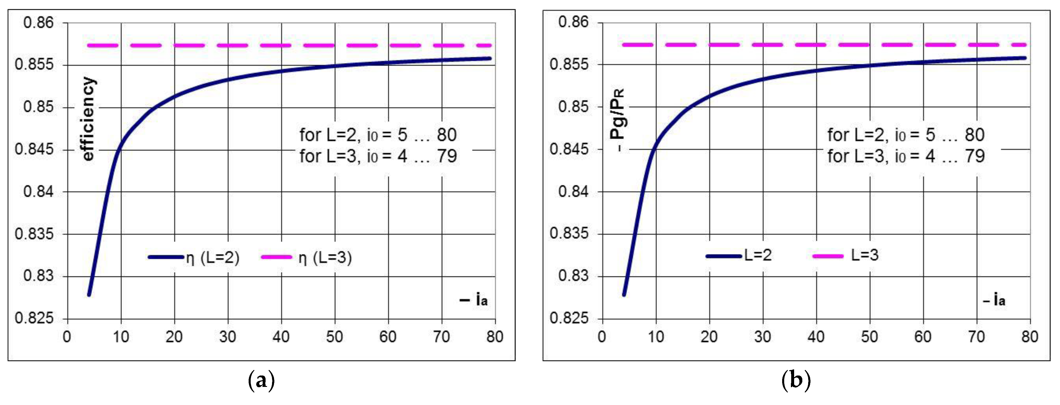
  • the efficiency of the gearbox with L = 2 and a fixed stator generator is steadily rising towards the interior efficiency ( η 0 ) with the increase of the absolute value of the multiplication ratio ( i a ) (Figure 11a).
  • the system with L = 3 (containing a generator with mobile and counter-rotating stator and rotor) is characterized by the following advantages compared to the conversion system with one input and one output (L = 2).
  • the gearbox efficiency is constant and equal to η 0 , not being influenced by the transmission interior kinematic ratio; therefore, the case with L = 3 is preferred to the system with L = 2 for small–medium values of the multiplication ratio ( | i a | < 30); for instance, for | i a | = 10 and η 0 = 0.857 the efficiencies are η L = 2 = 0.844 and η L = 3 = 0.857 , which lead to a relative increase of the efficiency of the L = 3 case with approximately 1.4%, versus the L = 2 system, and, therefore, a higher mechanical power of the counter-rotating generator (Figure 11a).
  • the increase with one unit of the relative speed between the rotor and stator of the counter-rotating generator (L = 3) brings a significant contribution to the multiplication ratio in the medium range; for instance, the multiplication ratio for i 0 = 4 is i a = 3 in the case L = 2, and i a = 4 in the case L = 3, leads to a relative increase with 33% of the multiplication ratio for the same gearbox type. Thus, for the same multiplication ratio, the case L = 3 allows the decrease of the interior kinematic ratio i 0 and of the radial dimension, implicitly, or a smaller input speed is required when using the same gearbox and the same relative speed in the counter-rotating generator (Figure 7); additionally, in the case L = 3 (Figure 11b), the generator input power ( P g ) and its output electric power, implicitly, are higher at the same input power of the conversion system.
  • for the same input torque | T R ( L = 2 ) | = | T R ( L = 3 ) | , the torque on the generator shaft is lower in the case L = 3, T g ( L = 3 ) < T g ( L = 2 ) , the differences between the two values being higher at smaller interior kinematic ratios. For instance, for i 0 = 10 and η 0 = 0.857 , the torque on the generator shaft in the case L = 3 is smaller by approximately 9% and the speed is higher by approximately 11% compared to the case L = 2; therefore, for the same wind power, the electric power generated by the conversion system in the case L = 3 (Figure 11b) is higher by approximately 1.4% than in the case L = 2, meaning that the counter-rotating generator starts sooner to produce energy than in the other case, as it has to overcome a smaller resistance.
T g ( L = 2 ) = η i a T R ,   T g ( L = 3 ) = η 0 i 0 T R ,   T g , ( L = 3 ) = i 0 η 0 i 0 T g ( L = 2 ) ,
as i 0 > + 1 , the ratio is i 0 η 0 i 0 < 1 T g ( L = 3 ) < T g ( L = 2 ) .
In conclusion, the advantages of the conversion system with a counter-rotating generator regarding the speed, efficiency and output power are more evident for small and medium values of the multiplication ratio. The increase of efficiency (which does not depend on the interior kinematic ratio) and of the generator output power are accompanied by a certain increase in complexity (due to the construction of the mobile stator of the generator); the comparative analysis of the weight of the two contradictory aspects becomes mandatory in the evaluation process.
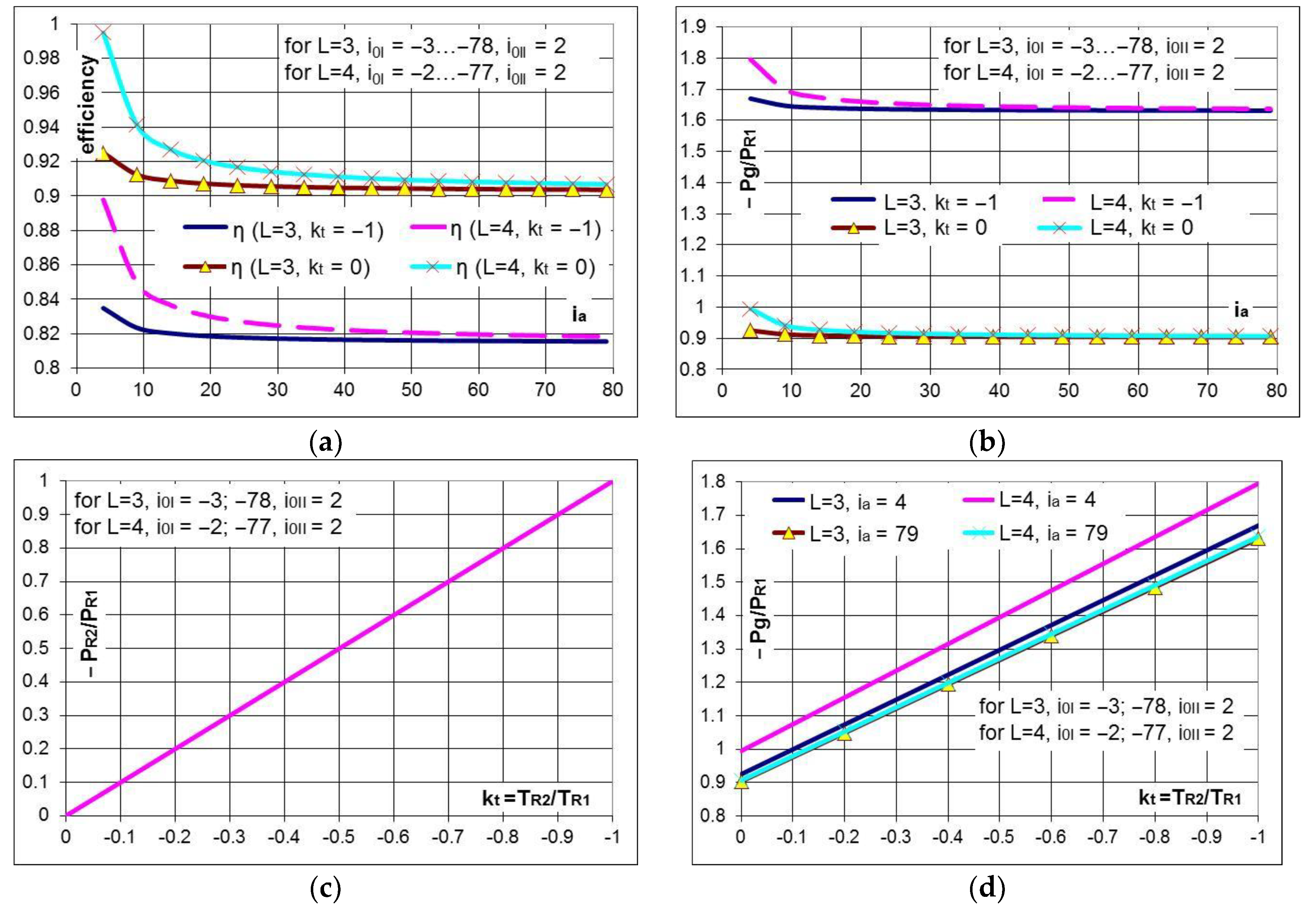
(b) RSV 2
Denoting the ratio of the torques on the rotors’ shafts by k t = + T R 2 / T R 1 , and considering that | T R 2 | | T R 1 | and that the two rotors are rotating in opposite directions, the ratio k t has negative and subunit values.
The results of the numerical simulations illustrated in Figure 12 highlight the following specific features of the RSV 2 variant:
  • for | k t | > 1 , the secondary rotor (R2) becomes the main rotor, which is less viable from a functional point of view; therefore, the case | k t | < 1 is further considered.
  • the gearbox efficiency is strongly influenced by the ratio k t , obtaining higher values of the efficiency for lower absolute values of this ratio; the efficiency decreases with the increase of the torque generated by R2 (Figure 12a); if the input torques on the two rotors are equal in absolute values ( | k t | = 1 ), the gearbox efficiency (Figure 12a) and the input power on the generator shaft, which is due to R1 (Figure 12b), decreases by approximately 10% relative to the case in which the torque given by the secondary rotor is null ( k t = 0 ).
  • the advantage of higher efficiency of the solutions with a mobile stator relative to the fixed stator case is practically insignificant for higher values of the multiplication ratio ( i a ) (Figure 12).
  • a linear increase of the power generated by the secondary rotor (Figure 12c) and of the total output power (Figure 12d) with the increase of the absolute value of k t is obtained by bringing into operation the secondary rotor ( | T R 2 | > 0 , | k t | > 0 ).
  • the mechanical power provided by the secondary rotor generates an increase in electric power, which can reach up to approximately 80% (Figure 12b) when the torque of the secondary rotor becomes equal to the torque given by the main rotor ( | k t | = 1 ).
  • the system with L = 4 (two inputs and two outputs) has the following advantages compared to the system with L = 3 (2 inputs and 1 output): the efficiency of the L = 4 speed increaser is higher to that of the L = 3 transmission, regardless of the value of input torques ratio ( k t ). For the same ratio ( k t ), the differences between the efficiency values are higher with up to 6% for low multiplication ratios and decrease with the increase of the multiplication ratio; for instance, the difference between efficiency values reaches approximately 3% for i a = 10 , η ( k t = 1 , L = 4 ) = 0.845 η ( k t = 1 , L = 3 ) = 0.821 (Figure 12a), which implies a slight increase in the output mechanical power that justifies the use of a counter-rotating generator (L = 4).
In conclusion, the WTs with a counter-rotating generator show high performances (higher speed, efficiency, and output power) for small values of the multiplication ratio; for multiplication ratios higher than 20, the use of the counter-rotating generator is not justified anymore. The advantages of the solution with a secondary counter-rotating wind rotor are obvious less through the efficiency contribution to the transmission, but especially through the additional generated power.
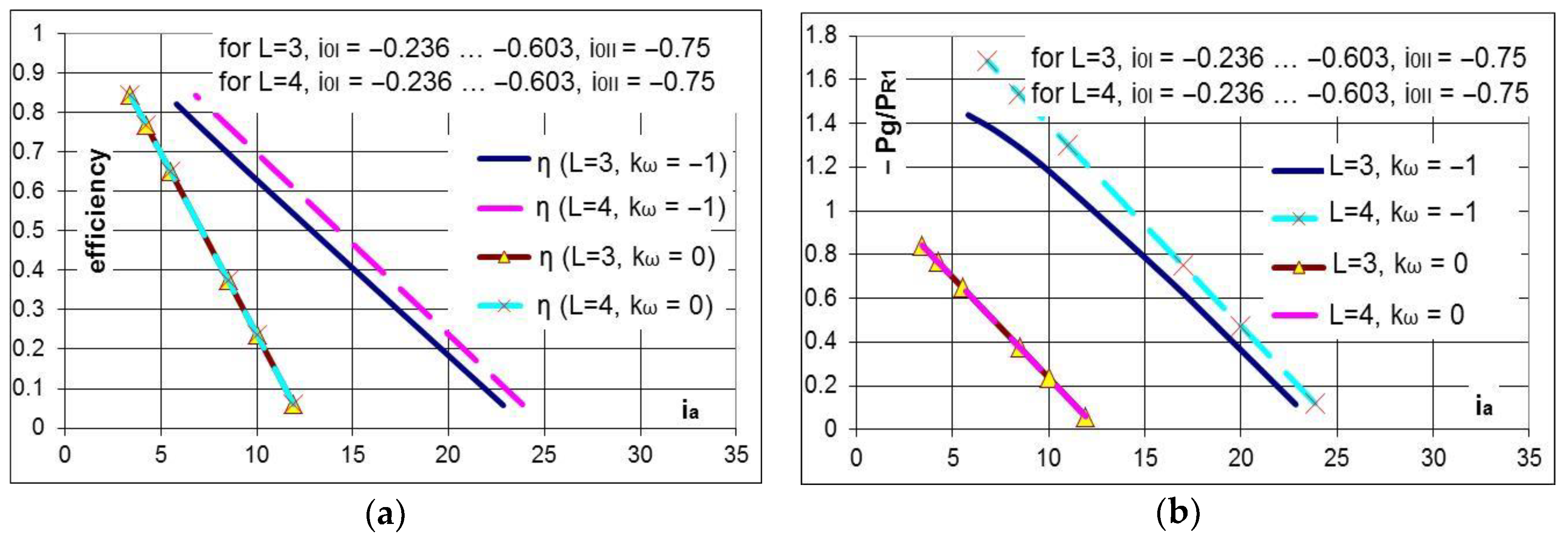
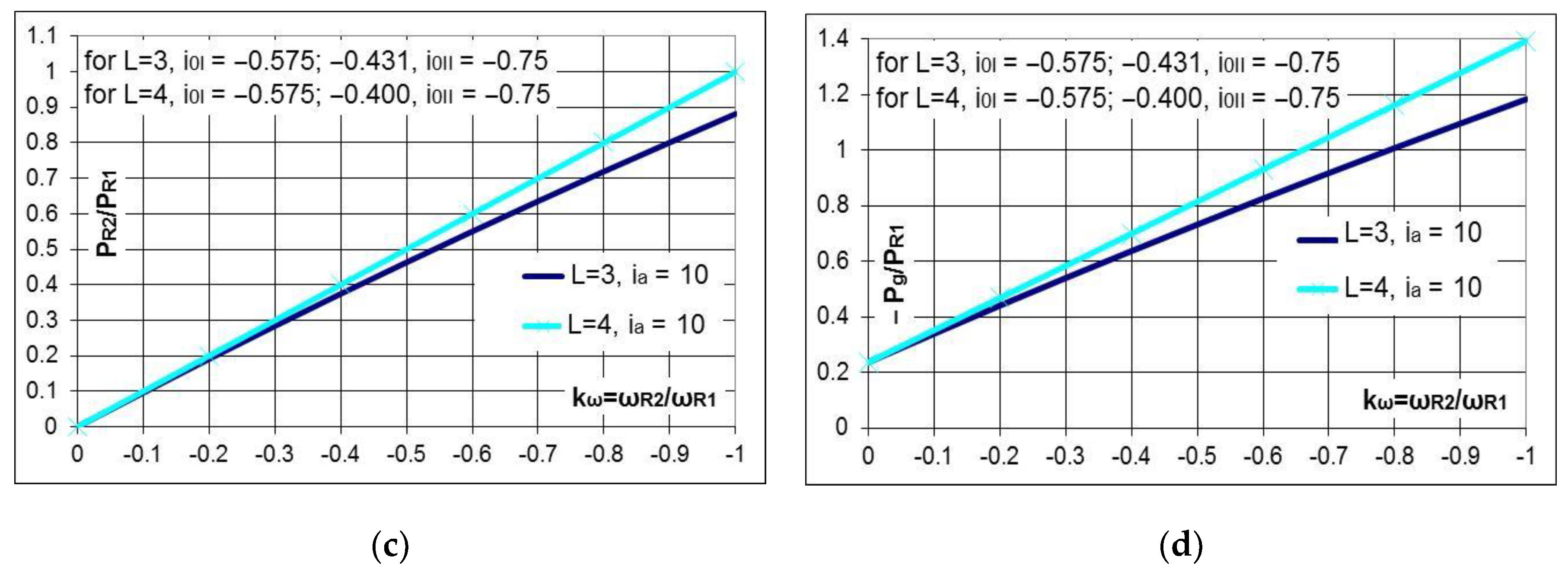
(c) RSV 3
Denoting the ratio of the two rotors’ speeds by k ω = ω R 2 / ω R 1 and considering that | ω R 2 | | ω R 1 | and that the two rotors R1 and R2 are rotating in opposite directions, the ratio k ω has negative subunit values.
The results of the numerical simulations illustrated in Figure 13 highlight the following specific features of the RSV 3 variant of the conversion system:
  • R2 becomes the main rotor for k ω < 1 , which is not viable from a functional point of view; therefore, the case k ω [ 1 , 0 ) is further analyzed.
  • the efficiency of the gearbox increases with the increase of the ratio | k ω | for the same multiplication ratio ( i a ). For instance, considering i a = 10 and L = 3, the efficiency almost triples in the case k ω = 1 ( η = 70 % ) compared to the case k ω = 0 ( η = 25 % ) (Figure 13a).
  • the efficiency values decrease with an increase in the multiplication ratio by a higher gradient as the module of the kω ratio is lower. Thus, these gearboxes can be implemented in wind turbines of medium and low power (with low multiplication ratios).
  • the gearbox efficiency decreases with the increase of the multiplication ratio (Figure 13a).
  • the power of the secondary rotor (Figure 13c) and the mechanical power of the generator (Figure 13b,d) (related to the main rotor power) increases with the increase of the | k ω | ratio.
  • the conversion system with L = 4 has the following advantages compared to the system with L = 3:
    -
    the solution containing a generator with a mobile stator (L = 4) ensures the efficiency increase with the increase of the ratio | k ω | ; for instance, for k ω = 1 , the efficiency in the case L = 4 is higher by approximately 10% to the case L = 3, regardless of the value of the multiplication ratio ( i a ) (Figure 13a).
    -
    the power generated by the secondary rotor ( P R 2 / P R 1 ) (Figure 13c) and the surplus of mechanical power on the generator shaft due to R2 ( P g / P R 1 ) (Figure 13b,d) increases with the increase of the ratio | k ω | module, these values being higher in the case L = 4.
In conclusion, these types of conversion systems are recommended for small and medium WTs that need small multiplication ratios; the increase of the multiplication ratio leads to the severe decrease of the efficiency. The advantages of the solution with a secondary counter-rotating wind rotor and a counter-rotating generator are more obvious when the two rotors have the same speed (the ratio | k ω | equals one).
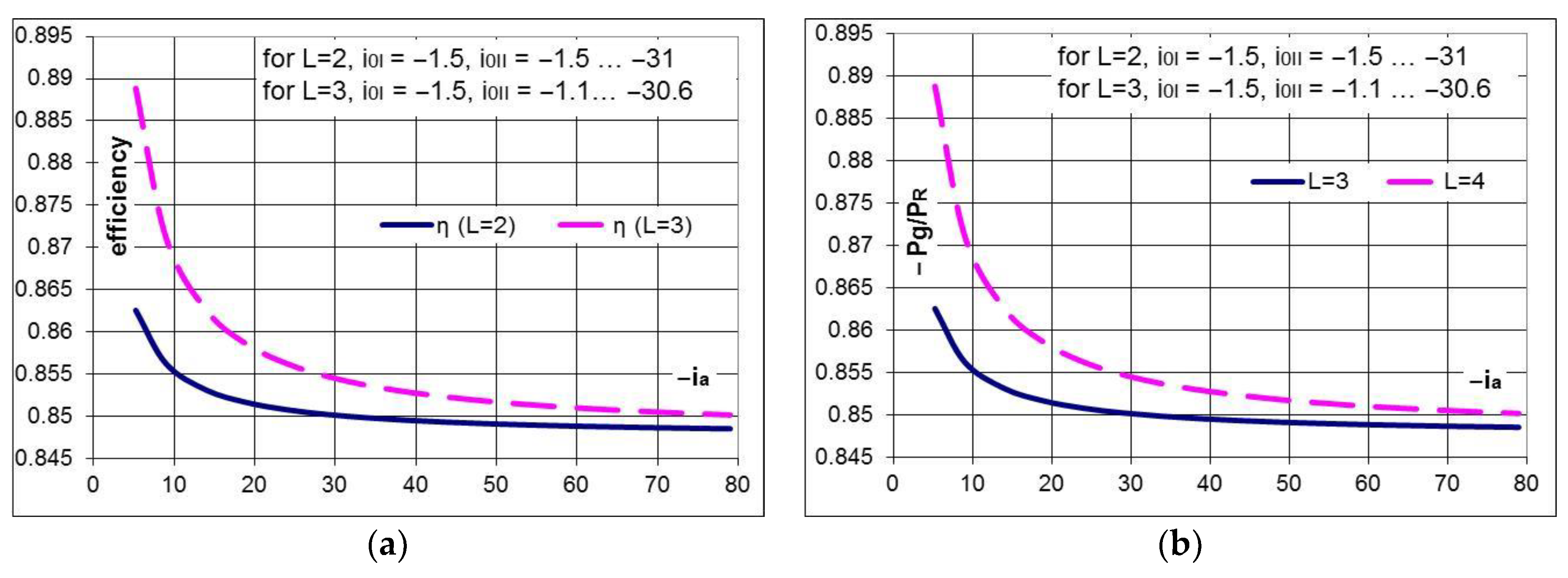
(d) RSV 4
The results of the numerical simulations depicted in Figure 14 highlight the following specific features of the RSV 4 variant:
  • due to the relatively good efficiencies, the solution can be applied to systems characterized by high absolute values of the multiplication ratio and limited radial dimensions; in these cases, a higher speed of the generator can be obtained by using two or more planetary gear trains as a speed increaser (Figure 10).
  • the gearbox efficiency is decreasing up to 1.5% for the case L = 2 and up to 4% for the L = 3 variant with the increase of the absolute value of the multiplication ratio ( | i a | ) (Figure 14a); the mechanical power at the generator input has the same characteristic (Figure 14b).
  • the system with L = 3, containing a counter-rotating generator has the advantage of a higher efficiency compared to the system with L = 2; this advantage becomes insignificant for higher values of the multiplication ratio:
    -
    the solution with L = 3 has a higher efficiency (Figure 14a) and a higher mechanical power (Figure 14b) than the L = 2 case for small values of the multiplication ratio. For instance, the efficiencies are η L = 2 = 0.855 , and η L = 3 = 0.87 (Figure 14a) for | i a | = 10 .
    -
    the variant with L = 2, containing a fixed stator generator achieves lower efficiencies and mechanical power but close to those of the mobile stator solutions (L = 3) for high absolute values of the multiplication ratio, the difference being approximately 1% (Figure 14); therefore, in these cases, the fixed stator variant is recommended to be used.
In conclusion, the RSV 4 variant with a counter-rotating generator is not recommended to be used due to its cost related to the surplus of power brought by the mobile stator. The fixed stator solutions are recommended when high multiplication ratio and limited radial dimensions are required.
The previous conclusions highlight that the analyzed systems can be installed in any type of wind turbine based on the location and implementation conditions, except RSV 3, which is suitable only for small and medium power applications.

4.4. Selection of the Conceptual Solution

Taking into account the previous conclusions and the implementation requirements (i.e., the technical restrictions: P 1 k W , i a 10 and η 0.8 ), the next step in the conceptual synthesis consists of obtaining the optimal (conceptual) solution (according to Figure 1—Step 7) by fine evaluation of the quantitative solving variants (RSV 1–4) associated to the representative qualitative solving variants. For the considered case study, the technical characteristics of the representative variants, deduced from the previous kinematic and static analysis, are synthesized in Table 4.
The WT conceptual solution (the solution with optimal kinematic configuration) is selected among the representative variants by fine evaluation on the basis of a set of criteria listed below in order of importance:
  • CA: Highest mechanical power of the generator;
  • CB: Highest efficiency of the speed increaser;
  • CC: Smallest axial size of the gearbox;
  • CD: Degree of complexity as low as possible.
The technical restriction regarding the minimum value of the efficiency ( η 0.8 ) is not fulfilled by RSV 3 and, therefore, this variant is eliminated from the fine evaluation. The remaining solving variants are further ordered according to Frisco method [47] based on the absolute ( W k ) and relative ( w k ) weight coefficients of each evaluation criteria (Table 5):
W k = 2 P k P min + S k + 0.5 0.5 n + P max P k ;   w k = W k , W k
where n is the criteria number (n = 4), Pk—the global grade of the k criterion = the sum of grades from k row, Sk = number of criteria whose global grades are inferior to the global grade of the current k criterion, Pmin/max—minimum/maximum value of Pk.
The ranking of the solving variants and the identification of the optimal solution is made based on the relative weight coefficients (wk) and the imposed evaluation criteria (Table 6):
The fine evaluation performed for the considered premises and criteria highlights that RSV 2 is the optimal solution. This variant consists of three feasible modules: two speed-dependent rotors—a planetary speed increaser with two inputs and two outputs—a counter-rotating electric generator (with a mobile stator and rotor). This conceptual solution is the input data for the embodiment design of the WT conversion system for the considered application.

5. Conclusions and Recommendations

This paper presents a new specific algorithm for the conceptual synthesis of speed increasers for wind turbine conversion systems, and based on the obtained results, useful recommendations for researchers and designers in the field of wind turbines are finally drawn.
The conceptual synthesis is the first phase in the development process of a system (or product) aiming to identify the optimal qualitative and quantitative solving variant (the concept) using a scientific approach based on a modelling algorithm. The algorithm proposed by the authors is specifically adapted to allow for the establishment of the conceptual solution of a speed increaser for wind turbines by applying a determined sequence of several steps starting from the requirements list: defining the system global function and sub-functions; identifying the structural variants that fulfil each sub-function; combining the structural variants into qualitative solving variants; rough evaluation of the qualitative solving variants; and fine evaluation of the quantitative solving variants based on imposed criteria and implementation conditions.
Thus, this synthesis algorithm is organized into two sections: the first section includes four steps for the approach at the WT system level aiming to deliver the needed specifications as input for the second section—the identification of the speed increaser concept in the other three steps. Based on the results of the first section, in the second section, a simplified example is presented that identifies the speed increaser conceptual solution for a particular wind turbine in order to illustrate the use of the proposed structural base of WT conversion systems. The algorithm can also be extended in the second section with specific steps for the other two sub-functions of global function, the conversion of the wind energy into mechanical energy and of the mechanical energy into electric energy, respectively.
Science and technology do not offer practical solutions for the direct conversion of wind energy into electricity (such as photovoltaic modules that directly convert solar power into electrical power); this conversion is currently obtained indirectly, through mechanical energy. Therefore, the conversion system of a wind turbine that is used to transform the wind energy into electric energy through two or three main sub-systems: wind rotor(s), speed increaser (if applicable) and electric generator. Each sub-system can be represented by several structural variants that fulfil a sub-function of the conversion system global function. The transformation of the wind energy into mechanical energy can be made by using one or two counter-rotating rotors. The electric generator converts the mechanical energy into electric energy and can function either with a fixed stator or a mobile stator (counter-rotating generator).
The solution of direct connection of the wind rotor to the electric generator presents technological difficulties, especially in industrial applications, due to the disparity between the relatively low wind turbine speeds and the higher speeds of the classical electric generators; although important steps have been taken in designing lower speed generators, in industrial applications, they cannot achieve the performances of conventional generators (with higher speeds). It is therefore necessary to use solutions, like the speed increasers, which allow a compatible connection between the low turbine speeds and higher generator speeds.
Each of the speed increaser variants can be characterized by several representative parameters:
(a)
the degree of freedom (one or two DOF).
(b)
the number of inputs: one or two wind rotors.
(c)
the number of outputs: one output (electric generator with a fixed stator) or two outputs (mobile and counter-rotating rotors and a stator).
(d)
the number of external links (L), i.e., the sum of inputs and outputs.
(e)
the (minimum) multiplication ratio, defined as the ratio between the equivalent generator speed (rotational speed of the rotor relative to the stator) and the wind rotor speed (in the case of two rotors: the higher rotor speed).
(f)
the mechanical efficiency, defined as the ratio between the output and input mechanical powers.
(g)
the (structural and technological) degree of complexity.
The speed increasing sub-function can be fulfilled by different structural variants as follows:
(a)
one DOF speed increaser with one input and one output (generator rotor) (L = 2).
(b)
one DOF speed increaser with one input (single wind rotor) and two outputs (counter-rotating generator) (L = 3); the mechanical driving of the rotor and stator of the electric generator is in opposite directions with speeds that are inversely proportional to their mechanical moments of inertia.
(c)
one DOF speed increaser with two inputs (counter-rotating wind rotors) and one output (generator rotor) (L = 3) and two independent torques; the mechanical summation of the two torsional torques (from the wind rotors) allows the increase of the output mechanical power.
(d)
one DOF speed increaser with two inputs (counter-rotating wind rotors) and two outputs (counter-rotating generator) (L = 4) and two independent torques.
(e)
two DOF speed increaser with two inputs (counter-rotating wind rotors) and one output (generator rotor) (L = 3) and two independent motions.
(f)
two DOF speed increaser with two inputs (counter-rotating wind rotors) and two outputs (counter-rotating generator) (L = 4) and two independent motions.
The increase of the electric energy generated by a WT conversion system can be achieved in different ways through:
(a)
maximization of the speed increaser efficiency.
(b)
increase of the speed at the generator by:
-
using a counter-rotating generator
-
summing up the motions of two counter-rotating wind rotors with a two DOF planetary transmission as a speed increaser
-
branching out the wind rotor motion with the help of a one DOF transmission and summing up the obtained motions with a two DOF planetary transmission
(c)
increase of the torque on the generator shaft by summing up the torques of two counter-rotating rotors through a one DOF transmission.
(d)
combination of the above solutions.
The design of the speed increaser for a WT conversion system has to take into account the following requirements:
(a)
the gearbox should be designed to be installed in a specific system that allows the conversion of the wind energy into electricity, based on the location and the implementation conditions.
(b)
if a speed increaser with a high multiplication ratio is requested, it is recommended to use a gearbox consisting of a one DOF planetary gear that allows branching out of the rotor speed, and a two DOF planetary gear that sums up the two motions, increasing the speed in this way (Figure 10).
(c)
although the use of a counter-rotating generator increases, to a certain extent, the complexity of the conversion system, the mobile stator of the generator adds additional speed and power, which becomes significant mainly for small and medium values of the multiplication ratio.
The mechanical power on the generator shaft can be also increased with a speed increaser through a surplus of torque or speed, depending on the type of gearbox used; the following relevant variants can be highlighted:
-
one DOF transmission that sums up the speeds of two rotors (Figure 6d1,d2,e1,e2,k1,k2).
-
two DOF transmission that sums up the speeds of two rotors (Figure 6f1,f2,g1,g2).
-
complex transmission containing a one DOF planetary gear, in which the motion of a rotor branches into two other motions, and a two DOF planetary gear, which sums up the two motions (Figure 6h1,h2,i1,i2,j1,j2).
The solving variants identified in Figure 6 and evaluated in Figure 7, Figure 8, Figure 9 and Figure 10 and Table 2 are the subject of four pending patents.
The explanation of the calculation models for the other classes of speed increasers, as well as of the relevant conceptual design cases, will constitute the objectives of subsequent papers. The dynamic analysis of the conversion system and the optimization of component selection based on the site wind potential and on the maximization of output power will be approached in another paper.

Author Contributions

The paper is the joint efforts of all the authors listed, their individual contributions being equally given on conceptualization, methodology, software, validation, analysis, investigation, resources, data curation, writing original draft preparation, writing review & editing, visualization.

Funding

This research received no external funding.

Conflicts of Interest

The authors declare no conflict of interest.

References

  1. Booker, J.D.; Mellor, P.H.; Wrobel, R.; Drury, D. A compact, high efficiency contra-rotating generator suitable for wind turbines in the urban environment. Renew. Energy 2010, 35, 2027–2033. [Google Scholar] [CrossRef]
  2. Lee, S.; Kim, H.; Son, E.; Lee, S. Effects of design parameters on aerodynamic performance of a counter-rotating wind turbine. Renew. Energy 2012, 42, 140–144. [Google Scholar] [CrossRef]
  3. Sapre, R.; Murkute, H.; Agrawal, R. Comparison between single axis wind turbine and counter wind turbine—A case study. Glob. J. Eng. Appl. Sci. 2012, 2, 144–146. [Google Scholar]
  4. Frost, W. Engineering Handbook on the Atmospheric Environmental Guidelines for Use in Wind Turbine Generator Development. NASA Technical Report no. 1359; 1978. Available online: https://ntrs.nasa.gov/search.jsp?R=19790006508 (accessed on 19 September 2017).
  5. Hau, E. Wind Turbines: Fundamentals, Technologies, Application, Economics, 2nd ed.; Springer: Berlin/Heidelberg, Germany, 2006; pp. 253–3018. ISBN 978-3-540-24240-6. [Google Scholar]
  6. Vișa, I.; Jaliu, C.; Duță, A.; Neagoe, M.; Comsit, M.; Moldovan, M.; Ciobanu, D.; Burduhos, B.; Saulescu, R. The Role of Mechanisms in Sustainable Energy Systems; Transilvania University of Brașov Publishing House: Brașov, Romania, 2015; pp. 218–316. ISBN 978-606-19-0571-3. [Google Scholar]
  7. Appa, K. Energy Innovations Small Grant (EISG) Program (Counter Rotating Wind Turbine System). EISG Final Report. 2002. Available online: http://www.eai.in/ref/invent/upload/00-09%2520FAR%2520Appendix%2520A.pdf (accessed on 11 June 2017).
  8. Jung, S.; No, T.; Ryu, K. Aerodynamic performance prediction of a 30 kW counter-rotating wind turbine system. Renew. Energy 2005, 30, 631–644. [Google Scholar] [CrossRef]
  9. McKenna, R.; Ostman, V.D.; Leye, P.; Fichtner, W. Key challenges and prospects for large wind turbines. Renew. Sustain. Energy Rev. 2016, 53, 1212–1221. [Google Scholar] [CrossRef]
  10. Lee, S.; Kim, H.; Lee, S. Analysis of aerodynamic characteristics on a counter-rotating wind turbine. Curr. Appl. Phys. 2010, 10, S339–S342. [Google Scholar] [CrossRef]
  11. Hwang, B.; Lee, S.; Lee, S. Optimization of a counter-rotating wind turbine using the blade element and momentum theory. J. Renew. Sustain. Energy 2013, 5, 052013. [Google Scholar] [CrossRef]
  12. Dong, W.; Xing, Y.; Moan, T. Time Domain Modeling and Analysis of Dynamic Gear Contact Force in a Wind Turbine Gearbox with Respect to Fatigue Assessment. Energies 2012, 5, 4350–4371. [Google Scholar] [CrossRef] [Green Version]
  13. Newman, B.G. Actuator-disc theory for vertical-axis wind turbines. J. Wind Eng. Ind. Aerodyn. 1983, 15, 347–355. [Google Scholar] [CrossRef]
  14. Farahani, E.M.; Hosseinzadeh, N.; Ektesabi, M. Comparison of fault-ride-through capability of dual and single-rotor wind turbines. Renew. Energy 2012, 48, 473–481. [Google Scholar] [CrossRef]
  15. No, T.S.; Kim, J.E.; Moon, J.H.; Kim, S.J. Modelling, control, and simulation of dual rotor wind turbine generator system. Renew. Energy 2009, 34, 2124–2132. [Google Scholar] [CrossRef]
  16. Climescu, O.; Jaliu, C.; Saulescu, R. Comparative Analysis of Horizontal Small Scale Wind Turbines for a Specific Application. In Proceedings of the 14th IFToMM World Congress, Taipei, Taiwan, 25–30 October 2015. [Google Scholar] [CrossRef]
  17. Kubo, K.; Hano, Y.; Mitarai, H.; Hirano, K.; Kanemoto, T.; Galal, A.M. Intelligent wind turbine unit with tandem rotors (discussion of prototype performances in field tests). Curr. Appl. Phys. 2010, 10, S326–S331. [Google Scholar] [CrossRef]
  18. Moghadassian, B.; Rosenberg, A.; Sharma, A. Numerical Investigation of Aerodynamic Performance and Loads of a Novel Dual Rotor Wind Turbine. Energies 2016, 9, 571. [Google Scholar] [CrossRef]
  19. Chantharasenawong, C.; Suwantragul, B.; Ruangwiset, A. Axial Momentum Theory for Turbines with Co-axial Counter Rotating Rotors. In Proceedings of the Commemorative International Conference of the Occasion of the 4th Cycle Anniversary of KMUTT Sustainable Development to Save the Earth: Technologies and Strategies Vision 2050: (SDSE2008), Bangkok, Thailand, 11–13 December 2008. [Google Scholar]
  20. Marjanovic, N.; Isailovic, B.; Marjanovic, V.; Milojevic, Z.; Blagojevic, M.; Bojic, M. A practical approach to the optimization of gear trains with spur gears. Mech. Mach. Theory 2012, 53, 1–16. [Google Scholar] [CrossRef]
  21. Bevingtoll, C.M.; Bywaters, G.L.; Coleman, C.C.; Costin, D.P.; Danforth, W.L.; Lynch, J.A.; Rolland, R.H. Wind Turbine Having a Direct-Drive Drivetrain. U.S. Patent No. 7431567B1, 7 October 2008. [Google Scholar]
  22. Mesquita, A.L.A.; Palheta, F.C.; Pinheiro Vaz, J.R.; Girão de Morais, M.V.; Gonçalves, C. A methodology for the transient behavior of horizontal axis hydrokinetic turbines. Energy Convers. Manag. 2014, 87, 1261–1268. [Google Scholar] [CrossRef]
  23. Neagoe, M.; Saulescu, R.; Jaliu, C.; Cretescu, N. Novel speed increaser used in counter-rotating wind turbines. New Adv. Mech. Mech. Transm. Robot. Mech. Mach. Sci. 2017, 46, 143–151. [Google Scholar] [CrossRef]
  24. Saulescu, R.; Neagoe, M.; Jaliu, C. Improving the energy performance of wind turbines implemented in the built environment using counter-rotating planetary transmissions. IOP Conf. Ser. Mater. Sci. Eng. 2016, 147, 012089. [Google Scholar] [CrossRef] [Green Version]
  25. Saulescu, R.; Neagoe, M.; Munteanu, O.; Cretescu, N. Performance analysis of a novel planetary speed increaser used in single-rotor wind turbines with counter-rotating electric generator. IOP Conf. Ser. Mater. Sci. Eng. 2016, 147, 012090. [Google Scholar] [CrossRef] [Green Version]
  26. Climescu, O.; Săulescu, R.; Jaliu, C. Specific features of a counter-rotating transmission for renewable energy systems. Environ. Eng. Manag. J. 2011, 10, 1105–1113. [Google Scholar]
  27. Saulescu, R.; Jaliu, C.; Neagoe, M. Structural and kinematic features of a 2 DOF speed increaser for renewable energy systems. Appl. Mech. Mater. 2016, 823, 367–372. [Google Scholar] [CrossRef]
  28. Saulescu, R.; Neagoe, M.; Jaliu, C.; Munteanu, O. Comparative analysis of two wind turbines with planetary speed increaser in steady-state. Appl. Mech. Mater. 2016, 823, 355–360. [Google Scholar] [CrossRef]
  29. Saulescu, R.; Jaliu, C.; Munteanu, O.; Climescu, O. Planetary gear for counter-rotating wind turbines. Appl. Mech. Mater. 2014, 658, 135–140. [Google Scholar] [CrossRef]
  30. Saulescu, R.; Jaliu, C.; Climescu, O.; Diaconescu, D. On the use of 2 DOF planetary gears as “speed increaser” in small hydros and wind turbines. In Proceedings of the ASME 2011 International Design Engineering Technical Conferences & Computers and Information in Engineering Conference, IDETC/CIE 2011, Washington, DC, USA, 28–31 August 2011; pp. 601–610, Paper No. DETC2011-47042. [Google Scholar] [CrossRef]
  31. Wacinski, A.; Sàrl, E. Drive Device for a Windmill Provided with Two Counter–Rotative Propellers. U.S. Patent No. 7384239B2, 10 June 2008. [Google Scholar]
  32. Herzog, R.; Schaffarczyk, A.P.; Wacinski, A.; Zürcher, O. Performance and stability of a counter–rotating windmill using a planetary gearing: Measurements and Simulation. EWEC 2010, 6, 4847. Available online: https://www.researchgate.net/publication/236683548 (accessed on 15 June 2017).
  33. Brander, M. Bi-Directional Wind Turbine. U.S. Patent US 2008/0197639 A1, 21 August 2008. [Google Scholar]
  34. Qiu, J.; Liu, B.; Dong, H.; Wang, D. Type Synthesis of Gear-box in Wind Turbine. Procedia Comput. Sci. 2017, 109C, 809–816. [Google Scholar] [CrossRef]
  35. Hall, J.F.; Mecklenborg, C.A.; Chen, D.; Pratap, S.B. Wind energy conversion with a variable-ratio gearbox: Design and analysis. Renew. Energy 2011, 36, 1075–1080. [Google Scholar] [CrossRef]
  36. Jelaska, D.; Podrug, S.; Perkusic, M. A novel hybrid transmission for variable speed wind turbines. Renew. Energy 2015, 83, 78–84. [Google Scholar] [CrossRef]
  37. Zhao, M.; Ji, J. Dynamic analysis of wind turbine gearbox components. Energies 2016, 9, 110. [Google Scholar] [CrossRef]
  38. Kanemoto, T.; Galal, A.M. Development of intelligent wind turbine generator with tandem wind rotors and double rotational armatures. JSME Int. J. Ser. B 2006, 49, 450–457. [Google Scholar] [CrossRef]
  39. Duong, M.Q.; Leva, S.; Mussetta, M.; Le, K.H. A Comparative Study on Controllers for Improving Transient Stability of DFIG Wind Turbines During Large Disturbances. Energies 2018, 11, 480. [Google Scholar] [CrossRef]
  40. Duong, M.Q.; Grimaccia, F.; Leva, S.; Mussetta, M.; Le, K.H. Improving Transient Stability in a Grid-Connected Squirrel-Cage Induction Generator Wind Turbine System Using a Fuzzy Logic Controller. Energies 2015, 8, 6328–6349. [Google Scholar] [CrossRef] [Green Version]
  41. Zhamalov, A.Z.; Obozov, A.D.; Kunelbaev, M.M.; Baikadamova, L.S. Capacity and Power Characteristics of Disk Generator with Counter-Rotation of Double-Rotor Wind Turbine. Middle-East J. Sci. Res. 2013, 15, 1655–1662. [Google Scholar] [CrossRef]
  42. Ribarov, L. Gearless Contra-Rotating Wind Generator. U.S. Patent US 2014/0008915, 9 January 2014. [Google Scholar]
  43. Cross, N. Engineering Design Methods: Strategies for Product Design; J. Wiley & Sons: New York, NY, USA, 2000; pp. 29–47. ISBN 978-0-471-87250-4. [Google Scholar]
  44. Ulrich, K.; Epinger, S. Product Design and Development, 4th ed.; McGraw-Hill, Inc.: New York, NY, USA, 2008; pp. 123–140. ISBN 978-007-125947-7. [Google Scholar]
  45. Pahl, G.; Beitz, W. Engineering Design. A Systematic Approach, 3rd ed.; Springer: London, UK, 2007; pp. 159–210. ISBN 987-1-84628-318-5. [Google Scholar]
  46. V.D.I. (Verein Deutscher Ingenieure)—Richtlinien 2221. Available online: https://www.vdi.de/nc/richtlinie/vdi_2221-methodik_zum_entwickeln_und_konstruieren_technischer_systeme_und_produkte/ (accessed on 15 November 2017).
  47. Diaconescu, D.; Neagoe, M.; Jaliu, C.; Saulescu, R. Products’ Conceptual Design; Transilvania University Publishing House: Brasov, Romania, 2010; pp. 140–160. ISBN 978-973-598-230-0. [Google Scholar]
  48. Jaliu, C.; Saulescu, R.; Diaconescu, D.; Neagoe, M. Conceptual design of a chain speed increaser for small hydropower stations. In Proceedings of the ASME 2009 International Design Eng. Technical Conf. & Computers and Information in Engineering Conf. IDETC/CIE 2009, San Diego, CA, USA, 30 August–2 September 2009; pp. 321–328. [Google Scholar] [CrossRef]
  49. Walliser, J. Wind Turbine Gear Mechanism. U.S. Patent US 2014/0128213A1, 8 May 2014. [Google Scholar]
  50. Schellstede, H. Wind Turbine Installation and Advance Double Counter-Rotating Blades, 90 Degree Drive Assembly with Lower Generator Mounting System. U.S. Patent US 2014/0015255 A1, 1 January 2014. [Google Scholar]
  51. Shinn, C.; Hur, M.C. Over–Drive Gear Device. U.S. Patent US 5222924, 29 June 1993. [Google Scholar]
  52. Kirschbaum, H. Wind Turbine-Generator. U.S. Patent US 4291233A, 22 September 1981. [Google Scholar]
  53. Caiozza, J. Wind Driven Electric Generator Apparatus. U.S. Patent US 7227276 B2, 5 June 2007. [Google Scholar]
  54. Winderl, W. Wind Operated Generator. U.S. Patent US 4039848A, 2 August 1977. [Google Scholar]
  55. Neagoe, M.; Săulescu, R.; Jaliu, C.; Munteanu, O.; Crețescu, N. Monomobile Counter-Rotating Wind Turbine. Patent RO A/00539/29.07.2016; in press (In Romanian).
  56. Sǎulescu, R.; Neagoe, M.; Vișa, M.; Jaliu, C.; Munteanu, O.; Totu, I.; Cretescu, N. Monomobile Planetary Speed Increaser with Two Counter-Rotating Outputs. Patent RO A/00905/25.11.2016; in press (In Romanian).
  57. Sǎulescu, R.; Neagoe, M.; Jaliu, C. Differential Planetary Speed Increaser with Two Counter-Rotating Outputs. Patent RO A/00326/30.05.2017; in press (In Romanian).
  58. Sǎulescu, R.; Neagoe, M.; Jaliu, C. Monomobile Planetary Speed Increaser with Two Inputs and Two Outputs. Patent RO A/00880/27.10.2017; in press (In Romanian).
  59. Miloiu, G.; Dudita, F.L.; Diaconescu, D. Modern Mechanical Transmissions, 2nd ed.; Tehnica Publishing House: Bucureşti, Romania, 1980; pp. 191–253. (In Romanian) [Google Scholar]
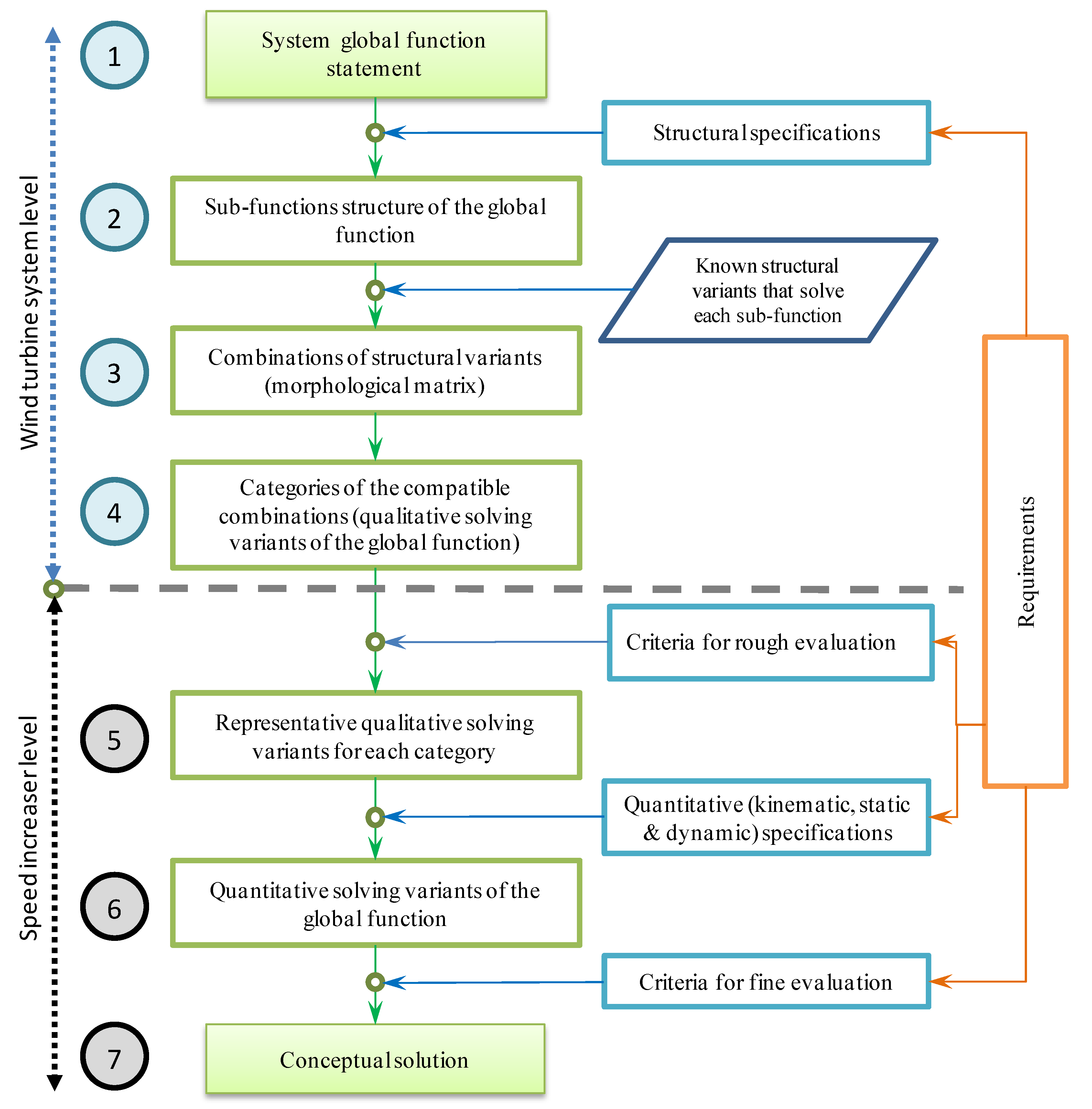
Figure 1. The proposed algorithm for the conceptual synthesis of speed increasers for wind turbines (WTs).
Energies 11 02257 g001
Figure 2. The sub-function structure of WT global function: FE1 = transformation of wind energy into mechanical energy; the structural variant for this function is represented by the wind rotor(s); FE2 = appropriate modification of mechanical energy parameters (transmission of mechanical energy with speed increase); the structural variant is the speed increaser; FE3 = transformation of mechanical energy into electrical energy, sub-function fulfilled by the electric generator. E = wind energy. E* = electric energy.
Energies 11 02257 g002
Figure 3. The morphological matrix.
Energies 11 02257 g003
Figure 4. WT speed increaser configurations. R = wind rotor. GR = generator rotor. GS = generator stator.
Energies 11 02257 g004
Figure 5. Conceptual configuration of WT conversion systems with speed increasers generated in Figure 4: (a) single-rotor R—one degree of freedom (DOF), speed increaser A—electric GR; (b) counter-rotating wind rotors R1, R2—one DOF/two DOF speed increaser A—electric GR; (c) single-rotor R—one DOF speed increaser A—counter-rotating generator (GS—generator stator, GR—generator rotor); (d) counter-rotating wind rotors R1, R2—one DOF/two DOF speed increaser A—counter-rotating generator GS, GR; (e) counter-rotating wind rotors R1, R2—dual distinct speed increasers A1, A2—counter-rotating generator GS, GR.
Energies 11 02257 g005
Figure 6. Structural solving variants for the wind turbine conversion system.
Energies 11 02257 g006aEnergies 11 02257 g006bEnergies 11 02257 g006cEnergies 11 02257 g006d
Figure 7. Structural scheme, speeds diagram and the main parameters of the representative solving variant of Category I (1—sun gear, 2 and 3—planetary gears, 4—ring (internal) gear, H—planetary carrier, xR = xGS—linear speed of the center point of the planetary gear 3, xGR—linear speed of the contact point of the gears 1 and 2, yR = yGS—distance from the center point of the planetary gear 3 to the central axis, yGR—radius of the gear 1, δR = δGS—angle associated to the angular speed ωR = ωH = ωGS, δGR—angle associated to the angular speed ωGR).
Energies 11 02257 g007
Figure 8. Structural scheme, speeds diagram and the main parameters of the representative solving variant of Category II (1—sun gear, 3 and 4—planetary gears, 2 and 5—ring gears, xR1—linear speed of the center point of the planetary gear 4, xGR—linear speed of the contact point of the gears 1 and 4, xR2 = xGS—linear speed of the contact point of the gears 2 and 3, yR1—distance from the center point of the planetary gear 4 to the central axis, yR2 = yGS—distance from the contact point of the gears 2 and 3 to the central axis, δR1,2—angle associated to the angular speed ωR1,2).
Energies 11 02257 g008
Figure 9. Structural scheme, speeds diagram and the main parameters of the representative solving variant of Category III (1—sun gear, 3 and 4—planetary gears, 2 and 5—ring gears, xR1—linear speed of the contact point of the gears 4 and 5, xGR—linear speed of the contact point of the gears 1 and 3, yR1—distance from the contact point of the gears 4 and 5 to the central axis).
Energies 11 02257 g009
Figure 10. Structural scheme, speeds diagram and the main parameters of the representative solving variant of Category IV (1 and 6—sun gears, 2 and 5—planetary gears, 3 and 4—ring gears, H1 and H2—carriers, xR—linear speed of the contact point of the gears 2 and 3, xGS—linear speed of the contact point of the gears 4 and 5, xGr—linear speed of the contact point of the gears 5 and 6, yR—distance from the contact point of the gears 2 and 3 to the central axis, yGS—distance from the contact point of the gears 4 and 5 to the central axis, yGR—radius of the gear 6).
Energies 11 02257 g010
Figure 11. The diagrams for the variation of: (a) efficiency η and (b) generator input power P g as function of the multiplication ratio i a .
Energies 11 02257 g011
Figure 12. Diagrams for the variation of: (a) efficiency η ; (b) generator input power relative to the main rotor power P g / P R 1 as functions of the multiplication ratio i a ; (c) the power of the secondary rotor P R 2 / P R 1 ; (d) the input power of the generator P g / P R 1 relative to the main rotor power as functions of the ratio k t .
Energies 11 02257 g012
Figure 13. Diagrams for the variation of: (a) efficiency η ; (b) generator input power P g / P R 1 relative to the main rotor power as functions of the multiplication ratio i a ; (c) the secondary rotor power P R 2 / P R 1 ; (d) generator input power P g / P R 1 relative to the main rotor power as functions of the ratio k ω .
Energies 11 02257 g013aEnergies 11 02257 g013b
Figure 14. Diagrams for the variation of: (a) efficiency η ; (b) generator power related to the rotor R power, P g / P R as function of the multiplication ratio i a .
Energies 11 02257 g014
Table 1. The angular speeds of wind rotors and electric generator for the qualitative solving variants from Figure 6 ( ω R —wind rotor speed, ω R 1 —main wind rotor speed, ω R 2 —secondary wind rotor speed, ω G R —generator rotor speed, ω G S —generator stator speed, Min/Max = the minimum/maximum absolute values of the variation range for angular speed and multiplication ratio).
SpeedωR = ωR1 ω R 2   ω G R   ω G S   i a = ω G = ω G R   ( G S = 0 ) i a = ω G = ω G R   ω G S
Category Figure 6 MinMaxMinMaxMinMaxMinMaxMinMax
1234567891011
I.a+1--−1.5−6+1+1−1.5−6−2.5−7
b--−2−5+1+1−2−5−3−6
c--+2.66+7−0.41−2.51+2.66+7+3.08+9.51
II.d−0.83−1.14+1.86+5.92−0.83−1.14+1.86+5.92+2.69+7.06
e−0.63−0.72+3.12+6−0.63−0.72+3.12+6+3.76+6.72
III.f−1−1+4+13−1−1+4+13+5+14
g−1−1.01+28.87+37.88−1−1.01+28.87+37.88+29.87+38.89
IV.h--+4+23−1−1.49+4+23+5+24.49
i--+3.45+13.25−0.63−1.04+3.45+13.25+4.09+14.29
j--−5.42−12.71+1+1−5.42−12.71−6.42−13.71
k−0.63−1.04+3.45+13.25−0.63−1.04+3.45+13.25+4.09+14.29
Table 2. Rough evaluation of the qualitative solving variants.
Figure 6I.II.III.IV.
Criterionabcdefghijk
C 1981010961010777
C 27107989899910
C 3109671010859108
2627232627252624252625
Place21321213212
Table 3. The technical characteristics of the representative solving variants (RSV).
Representative Solving VariantsRSV 1RSV 2RSV 3RSV 4
Figure78910
Characteristics
Number of teeth and the interior kinematic ratioz1 = 40
z2 = 90
z3 = 90
z4 = 400
i0 = 10
z1 = 36
z2 = 400
z3 = 225
z4 = 139
z5 = 314
i0I = −8.72
i0II =1.27
z1 = 300
z2 = 400
z3 = 50
z4 = 25
z5 = 375
i0I = −0.4
i0II = −0.75
z1 = 296
z2 = 32
z3 = 360
z4 = 400
z5 = 143
z6 = 114
i0I = −1.21;
i0II = −3.5
Multiplication ratio−109.99310−9.992
Efficiency of a gear pair η g 0.950.950.950.95
Table 4. The technical characteristics of the representative quantitative solving variants.
Representative Solving VariantRSV 1RSV 2RSV 3RSV 4
Figure78910
Characteristics
Multiplication ratio−109.99310−9.992
Efficiency of a gear pair ηg0.950.950.950.95
Efficiency of the speed increaser0.8570.845–0.937
k t = T R 2 T R 1 = 1...0
0.237–0.696
k ω = ω R 2 ω R 1 = 1...0
0.87
Mechanical power at the generator input P g [kW]0.8571.69–0.937
k t = T R 2 T R 1 = 1...0
1.39–0.237
k ω = ω R 2 ω R 1 = 1...0
0.87
Table 5. The relative weight coefficients (Lk = the place of the current k criterion according to the Pk values hierarchy).
kCriterionCACBCCCDPkLkSkWkwk
1CA0.51113.513200.805
2CB00.5112.5223.50.140
3CC000.511.5311.140.046
4CD0000.50.5400.20.009
24.841
Table 6. Concept selection by ordering the solving variants (Nk—the grade on the scale of 1 to 10 awarded to the k criterion for a given solving variant).
RSV 1RSV 2RSV 4
CriterionwkNkwk·NkNkwk·NkNkwk·Nk
CA0.80564.83108.05075.635
CB0.14081.12101.40091.260
CC0.046100.4690.41480.368
CD0.009100.0990.08170.063
346.5389.945317.326
Place: Energies 11 02257 i0013 Energies 11 02257 i0011 Energies 11 02257 i0012