Article

MPPT and SPPT Control for PV-Connected Inverters Using Digital Adaptive Hysteresis Current Control

Internet of Energy Laboratory, Department of Technology Management for Innovation, the University of Tokyo, Tokyo 113-8656, Japan
*
Author to whom correspondence should be addressed.
Energies 2018, 11(8), 2075; https://doi.org/10.3390/en11082075
Submission received: 8 July 2018 / Revised: 30 July 2018 / Accepted: 6 August 2018 / Published: 9 August 2018
(This article belongs to the Special Issue Design and Control of Power Converters 2019)

Abstract

:
Most PV systems are usually controlled by a Maximum Power Point Tracking (MPPT) algorithm to maximize the generated electrical power. However, the maximum power is often unstable and depends on the solar irradiance and temperature. This makes it difficult to control the power grid supply-demand balance due to fluctuations caused by the increase of renewable and variable PV systems. This paper proposes a new control algorithm for a PV-connected inverter called Specified Power Point Tracking (SPPT) control in addition to the conventional Maximum Power Point Tracking (MPPT) control. The PV system is controlled to generate the maximum power or a specified power depending on the electricity transactions comes from the electricity trading system. A high-speed FPGA-based digital adaptive hysteresis current control method, which has fast and stable response and simple structure comparing with the popular Sine-triangle Pulse Width Modulation (SPWM) method, is proposed to implement the MPPT and SPPT control. The adaptive hysteresis current band is calculated adaptively to improve a disadvantage of the classical fixed band hysteresis current control on the varying switching frequency. A reference current used in the adaptive hysteresis current control is calculated such that the output power of the PV-connected inverter is maximized in the MPPT control or is maintained at a given value in the SPPT control. The experimental and simulation results show that the PV-connected inverter under the proposed control algorithm generates the desired power almost exactly and yields stable and fast response despite the varying irradiance.

1. Introduction

Nowadays, renewable energy has become a solution to address the energy security concerns and emission standards of most countries. Photovoltaic (PV) energy systems have gained tremendous attention as one of the most promising renewable energy sources due to their advantages on the power scalability, simple installation, and low operating cost [1]. In most PV systems, the PV arrays are usually controlled by a Maximum Power Point Tracking (MPPT) algorithm to maximize the generated electrical power [2]. However, the Maximum Power Point (MPP) of the PV panel is unstable and varies with solar irradiance and temperature. This may cause problems such as voltage rise and protection problems in the utility grid [3]. Furthermore, it is difficult to control the supply-demand balance with the current power grid architecture due to fluctuations caused by the increase of renewable and variable energy generations like PV systems [4,5].
In Japan, at the end of August 2014, 1,368,749 PV projects with the total power of 69.4 GW had been approved. At that time, Kyushu Electric Power Company had approved PV generators with a capacity of 17.76 GW, which surpassed its maximum demand in summer (15.2 GW). The power company was unable to accept more PV energy and had to suspend responses to applications for grid connection contracts for new PV projects. After that, the same issue has been raised with other power companies in Japan, such as Hokkaido Electric Power (HEPCO), Tohoku Electric Power, Shikoku Electric Power, and Okinawa Electric Power [6]. There is still a limit for the current power grid to accept the increasing PV generators.
In order to maintain the reliability of the current power grid while accepting more and more penetration of renewable energy, such as PV, a new power system concept called digital grid has been proposed [7]. The digital grid enhances the current grid by dividing a large-scale synchronized power system into some smaller size power systems called digital grid cell. The digital grid cells connect together, to the current grid, and other distributed generations via a digital grid router (DGR). In this work, in order to reduce the effect of the demand-supply balance problem caused by the PV generators in the digital grid system, we propose a control algorithm for the PV-connected inverter called Specified Power Point Tracking (SPPT) control in addition to the conventional MPPT control. The control of the PV generator is decided based on the electricity transactions that the DGR receives from the electricity trading system.
Three major classes of current control techniques have been developed over the last few decades: predictive dead-beat, sine-triangle pulse width modulation (SPWM), and hysteresis current control [8]. While the predictive dead-beat control technique tends to give accurate responses, it is complicated for implementation and its accuracy depends on the accuracy of the predictive model [9]. The asynchronous SPWM is the most popular technique and is being used in most MPPT control algorithms in PV systems, such as perturb and observe (P&O), or incremental conductance (InC) [10,11], however, it requires complicated proportional-integral (PI) regulators with undesirable delays. On the other hand, the hysteresis current control has simple structure, fast response, and independent of the inverter system parameters [12]. Because a low sampling frequency may lead to a large ripple current overshoot from the hysteresis current band, a digital hysteresis current control usually requires AD converters with sufficiently high sampling frequency to contain the ripple current within the band accurately [13]. A high sampling frequency at MHz level may be difficult for implementation on conventional microcontrollers and digital signal processors (DSPs), however, such high sampling frequency is beyond the scope of the field programmable gate array (FPGA), which can execute calculations stably at a high frequency and is becoming more and more popular in many electronics applications [14,15].
The basic implementation of hysteresis current control bases on the switching signal derived by comparing the actual current and the tolerance band of the reference current. In classical hysteresis current control, the hysteresis current band is fixed to a certain value, which makes the switching frequency vary to contain the current within the band. This leads to unwanted heavy interference among the phases in the three-phase system. In order to solve this problem, an adaptive hysteresis current control technique has been developed and applied to control the grid-connected and stand-alone multi-functional inverter of the DGR [16,17]. In this study, we propose the novel SPPT control in addition to the conventional MPPT for the PV-connected multi-functional inverter, and a method to implement the control algorithms by a high-speed FPGA-based digital adaptive hysteresis current control.
This paper is organized as follows: Section 2 introduces the concepts of digital grid and digital grid router. The digital adaptive hysteresis current control technique is presented in Section 3. Section 4 presents the MPPT and SPPT control algorithm for the PV-connected inverter using the adaptive hysteresis current control. In Section 5, the experimental and simulation results are shown to illustrate the performances of the proposed method. Conclusions are given in Section 6.

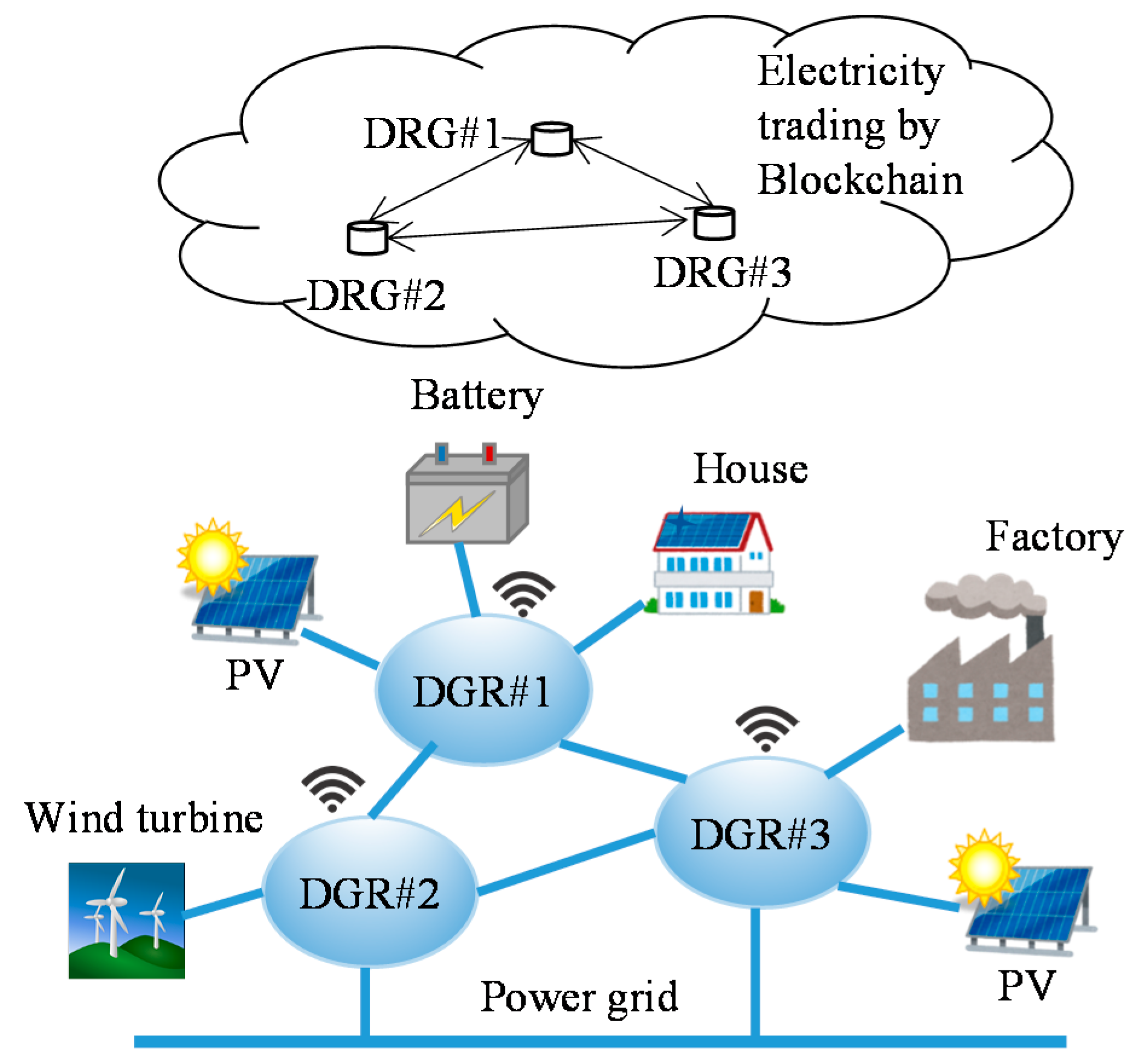
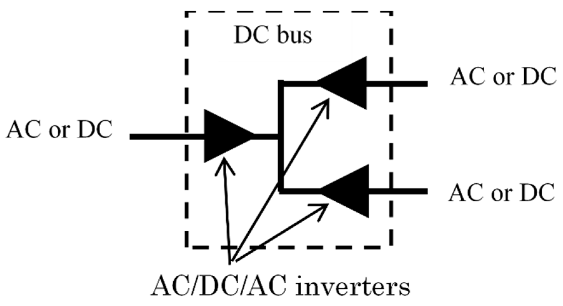
2. Digital Grid Router

The main concept of the digital grid is dividing a large synchronous grid into smaller segmented grid cells, which connect together, to the current grid, and other distributed generations via the DGR as shown in Figure 1 [18]. The DGR controls power flow of the equipment within a cell based on the trading results receiving from the electricity trading system. The DGR also plays a role of a shock absorber so that intermittent renewable energy sources in digital grid cells will not affect the main grid. It can be used to support the stability of the main grid via energy storage such as batteries. The DGR is composed of multi-functional inverters connected to a common DC bus as shown in Figure 2. Each inverter may connect to a grid, load, PV panel, battery, or a DC sub-grid.
The electricity trading within the digital grid bases on the demand and the supply ability in each digital grid cell, whose states are sent to the trading system on the cloud by a communication network. The smart-contracts using block-chain technology enable the electricity transactions to be operated automatically with the trading algorithm likes Zaraba method [19] in stock markets. This power grid system is expected to produce a free-electricity market between decentralized grids and enable the power grid to be adaptive to the instability due to peak-demand cutting and demand-response matching issues.

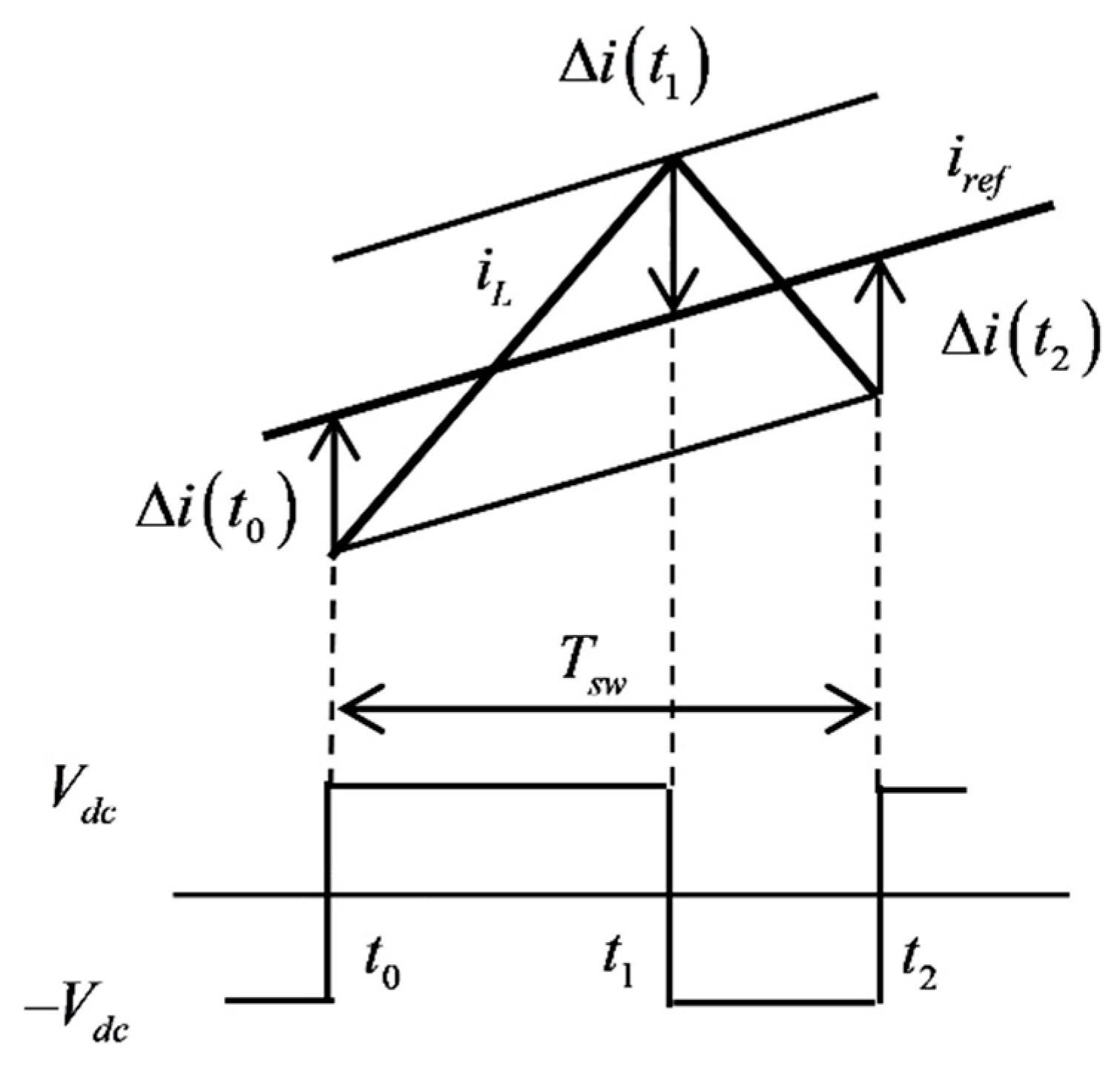
3. Adaptive Hysteresis Current Control

Consider a single-phase half-bridge inverter circuit as shown in Figure 3. The inverter has two constant and balanced DC sources, each of which has a value of V d c . Parameters L , L g , and C .
Represent the hysteresis inductance, output inductance, and capacitance of the ripple current filter, respectively. Let the output current io of the inverter be controlled by switch devices S1 and S2 to track a given reference current iref The adaptive hysteresis current control is employed as shown below [16].
Define the current error Δ i ( t ) as:
Δ i ( t ) = i L ( t ) i r e f ( t ) ,
where i L ( t ) and i r e f ( t ) are the hysteresis current and the reference currents at the instant t . Consider an instant t 0 , when the hysteresis current i L starts to cross the lower hysteresis band, and the switch S 1 is switched on. Assume that the switch S 1 is switched on during [ t 0 ,   t 1 ) , and is switched off during [ t 1 ,   t 2 ) intervals as shown in Figure 4.
A dynamic equation for the hysteresis current can be written as:
L d i L ( t ) d t = v d c ( t ) v o ( t ) ,
for t 0 t t 2 , where v o is the instantaneous output voltage and v d c ( t ) is the inverter input DC voltage elaborated as:
v d c ( t ) = { V d c i f   S 1   i s   O n V d c i f   S 1   i s   O f f .
Define the slopes of the hysteresis current in the on and off switching periods by I ˙ o n and I ˙ o f f respectively. By assuming that the output voltage v o is slowly varying during the switching modulation period [ t 0 ,   t 2 ] , the hysteresis current slopes can be expressed by:
s o n = d i L ( t ) d t = V d c v o ( t 0 ) L
for t [ t 0 ,   t 1 ) , and:
s o f f = d i L ( t ) d t = V d c v o ( t 0 ) L
for t [ t 1 ,   t 2 ) .
The current errors at t 1 and t 2 are given by:
Δ i ( t 1 ) = i L ( t 1 ) i r e f ( t 1 ) = i r e f ( t 0 ) + Δ i ( t 0 ) + s o n T o n i r e f ( t 1 )
Δ i ( t 2 ) = i L ( t 2 ) i r e f ( t 2 ) = i r e f ( t 0 ) + Δ i ( t 0 ) + ( s o n T o n + s o f f T o f f ) i r e f ( t 2 )
where:
T o n = t 1 t 0 ,
T o f f = t 2 t 1 .
The reference current i r e f ( t ) is slowly varying during the modulation period, such that it can be approximated as:
i r e f ( t 1 ) = i r e f ( t 0 ) + d i r e f ( t 0 ) T o n ,
i r e f ( t 2 ) = i r e f ( t 0 ) + d i r e f ( t 0 ) ( T o n + T o f f ) ,
where d i r e f ( t 0 ) is derivative of the reference current i r e f ( t ) with respect to t at t = t 0 .
Substituting Equations (10) and (11) into Equations (6) and (7), we can write the current errors Δ i ( t 1 ) , and Δ i ( t 2 ) as:
Δ i ( t 1 ) = Δ i ( t 0 ) + s o n T o n ,
Δ i ( t 2 ) = Δ i ( t 0 ) + s o n T o n + s o f f T o f f = Δ i ( t 1 ) + s o f f T o f f ,
where s o n , s o f f are given as:
s o n = s o n d i r e f ( t 0 ) = V d c v o ( t 0 ) L d i r e f ( t 0 ) ,
s o f f = s o f f d i r e f ( t 0 ) = V d c v o ( t 0 ) L d i r e f ( t 0 ) .
Let f s w is a desired constant switching frequency. In the adaptive hysteresis current control method, the hysteresis current band Δ i b ( t 0 ) is derived by using the following conditions:
Δ i ( t 1 ) Δ i ( t 0 ) = 2 Δ i b ( t 0 ) ,
Δ i ( t 2 ) Δ i ( t 1 ) = 2 Δ i b ( t 0 ) ,
T o n + T o f f = T s w ,
where T s w = 1 / f s w . Substituting Equations (16)–(18) into Equations (12) and (13), we can derive the hysteresis current band as:
Δ i b ( t 0 ) = 1 2 f s w s o n s o f f s o f f s o n .
By substituting Equations (14) and (15) into Equation (19), the hysteresis current band in Equation (19) can also be written in the form of:
Δ i b ( t 0 ) = 1 4 L f s w V d c { V d c 2 [ v o ( t 0 ) + L d i r e f ( t 0 ) ] 2 } .
For a digital control system, where the measured voltage and current is sampled by analog/digital converters, the hysteresis current band under zero-order-holds (ZOHs) can be written by:
Δ i b ( t ) = 1 4 L f s w V d c { V d c 2 [ v o ( k T s p ) + L d i r e f ( k T s p ) ] 2 } ,
where k T t < ( k + 1 ) T and T is a sampling interval.

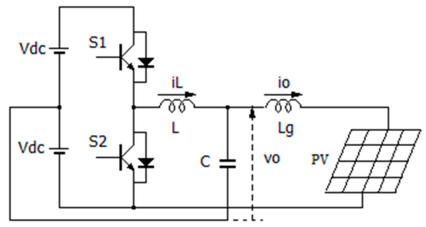
4. Hysteresis Current Control for PV-Connected Inverter

Consider a half-bridge inverter circuit with a PV panel connected between the output and the negative voltage of the inverter as shown in Figure 5. The voltage of the PV panel can be calculated from the output voltage v o of the inverter as:
V = v o + V d c .
The algorithms for MPPT and SPPT controls are described below.

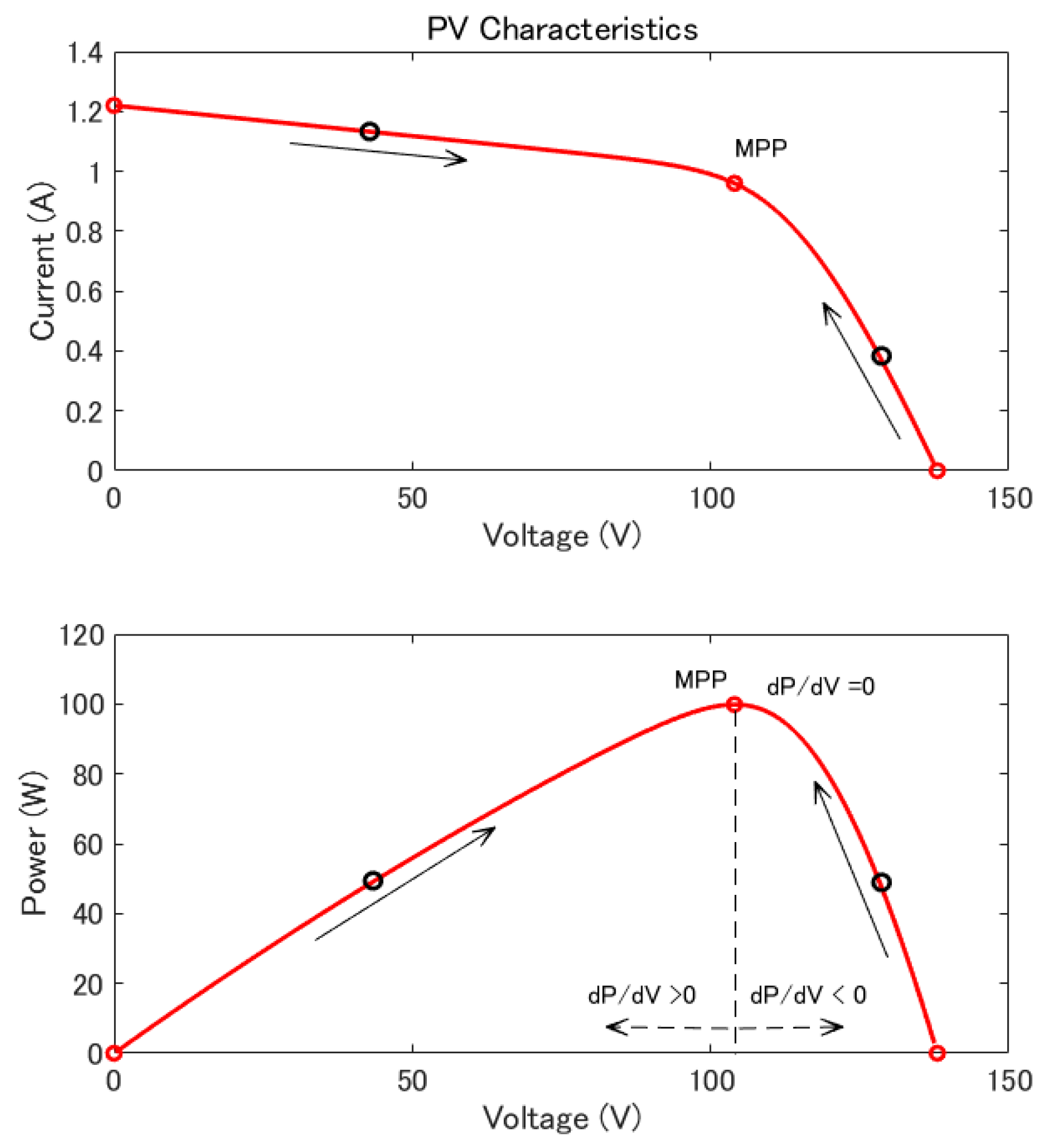
4.1. Algorithm for MPPT Control

Figure 6 shows voltage-current and voltage-power characteristic curves of the PV panel. The maximum power point (MPP) can be determined by a point, at which the derivative of output power P with respect to the voltage V is zero, i.e.:
d P d V = 0 .
Consider a digital control system, where the measured voltage and current are sampled by analog/digital converters with a sampling interval T . Let sampled-values of the voltage and current of the PV at a sampled instant k T are V k and I k . Then, the power P k at instant k T is calculated as:
P k = V k I k .
The derivative of the power with respect to the voltage at instant k T for the sampled-value can be written by:
d P d V | k = Δ P k Δ V k = P k P k 1 V k V k 1 .
The algorithm for hysteresis current control tracking the MPP is as below:
1 :   if   Δ P k Δ V k = 0 2 : i r e f _ k = i r e f _ k 1 3 :   else 4 : if   Δ P Δ V > 0 5 : i r e f _ k = i r e f _ k 1 + δ i 6 : else 7 : i r e f _ k = i r e f _ k 1 δ i
where δ i > 0 is a step-size of the reference current. It should be noted that due to the definition for direction of the output current from the inverter as shown in Figure 5, the reference current in this case takes only negative value.
The MPP divides the characteristics of the PV panel into two areas: positive power derivative d P / d V and negative power derivative d P / d V as shown in Figure 6. When the state of the PV panel is in the positive power derivative area, the reference current is decreased. On the contrary, when the state of the PV panel is in the negative power derivative area, the reference current is increased by a step-size δ i . This process is continued until the state of the PV arrives the MPP. At the MPP, the reference current is unchanged. While the reference current is changed by the definite step-size δ i , the output power of the PV panel may not identify to the MPP exactly. In order to avoid an oscillation of the reference current at the steady stay around the MPP, the MPP can be replaced by a maximum power bandwidth. Then, the MPPT algorithm can be revised as below.
1 :   if   | Δ P k Δ V k | δ P M 2 : i r e f _ k = i r e f _ k 1 3 :   else 4 : if   Δ P Δ V > δ P M 5 : i r e f _ k = i r e f _ k 1 + δ i 6 : else 7 : i r e f _ k = i r e f _ k 1 δ i
where δ P > 0 is the bandwidth of the MPP.

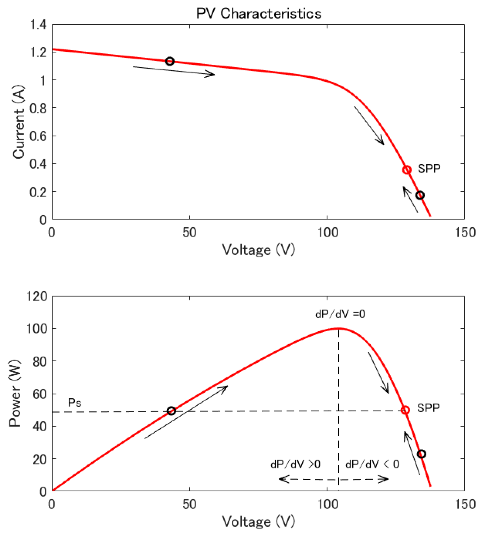
4.2. Algorithm for SPPT Control

Let the PV-connected inverter is controlled to generate a given specified power P s , which is assumed to be less than the generable maximum power. There are two points on the characteristic curves of the PV panel can generate the given power P s as shown in Figure 7.
However, in order to reduce the power loss, the point in the positive power derivative area, which has smaller current, is preferred. The algorithm tracking the specified power point (SPP) is as below:
1 :   if   P k = P s 2 : i r e f _ k = i r e f _ k 1 3 :   else 4 : if   ( k < P s ) P ( Δ P Δ V < 0 ) 5 : i r e f _ k = i r e f _ k 1 δ i 6 : else 7 : i r e f _ k = i r e f _ k 1 + δ i
The reference current is unchanged when the output power equals to the given power P s . When the output power is less than the given power P s and the state of the PV panel is in the negative power derivative area of the SPP, the reference current is increased. In the other cases, the reference current is decreased by the step-size δ i . This process is continued until the state of the PV panel arrives the SPP. By the same way of the MPPT control, in order to avoid an oscillation of the reference current at the steady state around the SPP, the SPP can be replaced by a specified power bandwidth. Then, the SPPT algorithm can be revised as below:
1 :   if   | P k P s | δ P S 2 : i r e f _ k = i r e f _ k 1 3 :   else 4 : if   ( P k < P s δ P S ) ( Δ P Δ V < 0 ) 5 : i r e f _ k = i r e f _ k 1 δ i 6 : else 7 : i r e f _ k = i r e f _ k 1 + δ i
where δ P S > 0 is the specified power bandwidth.

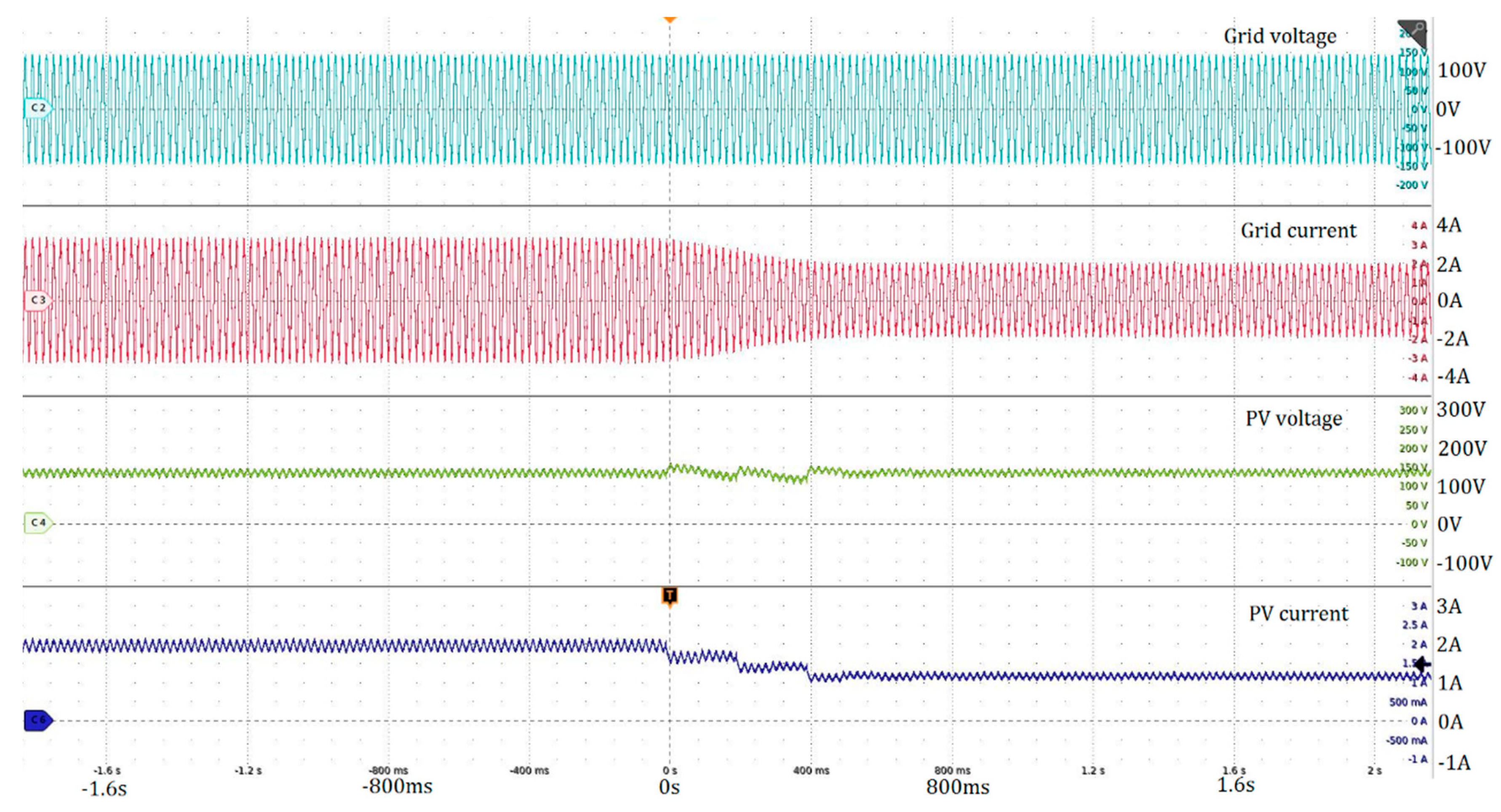
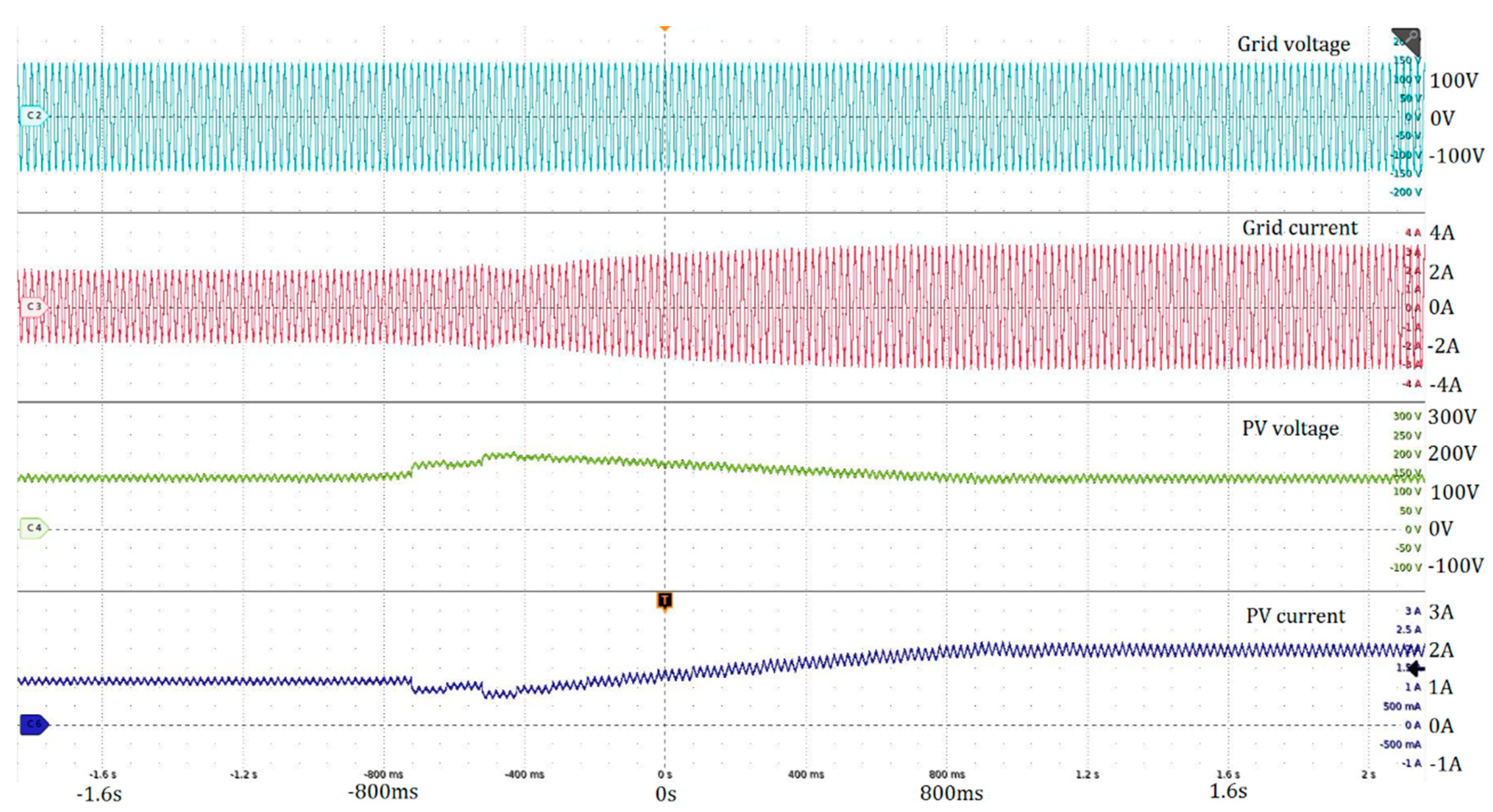
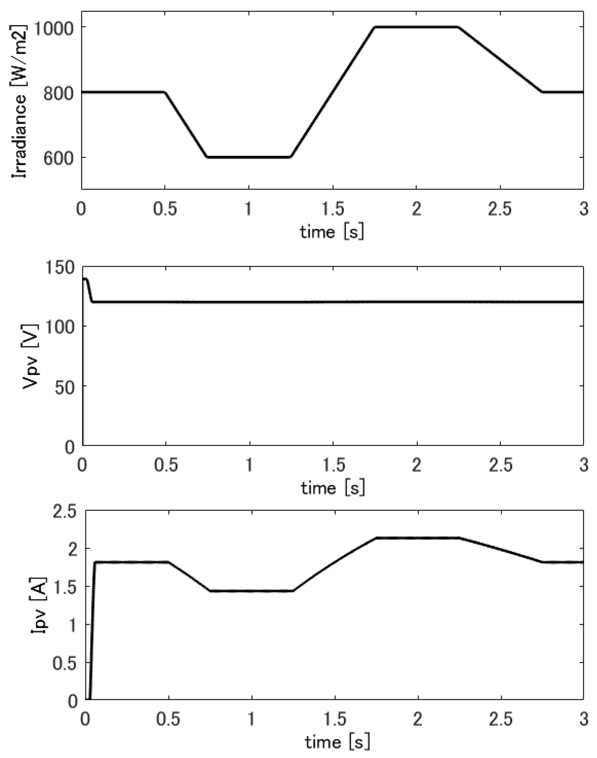
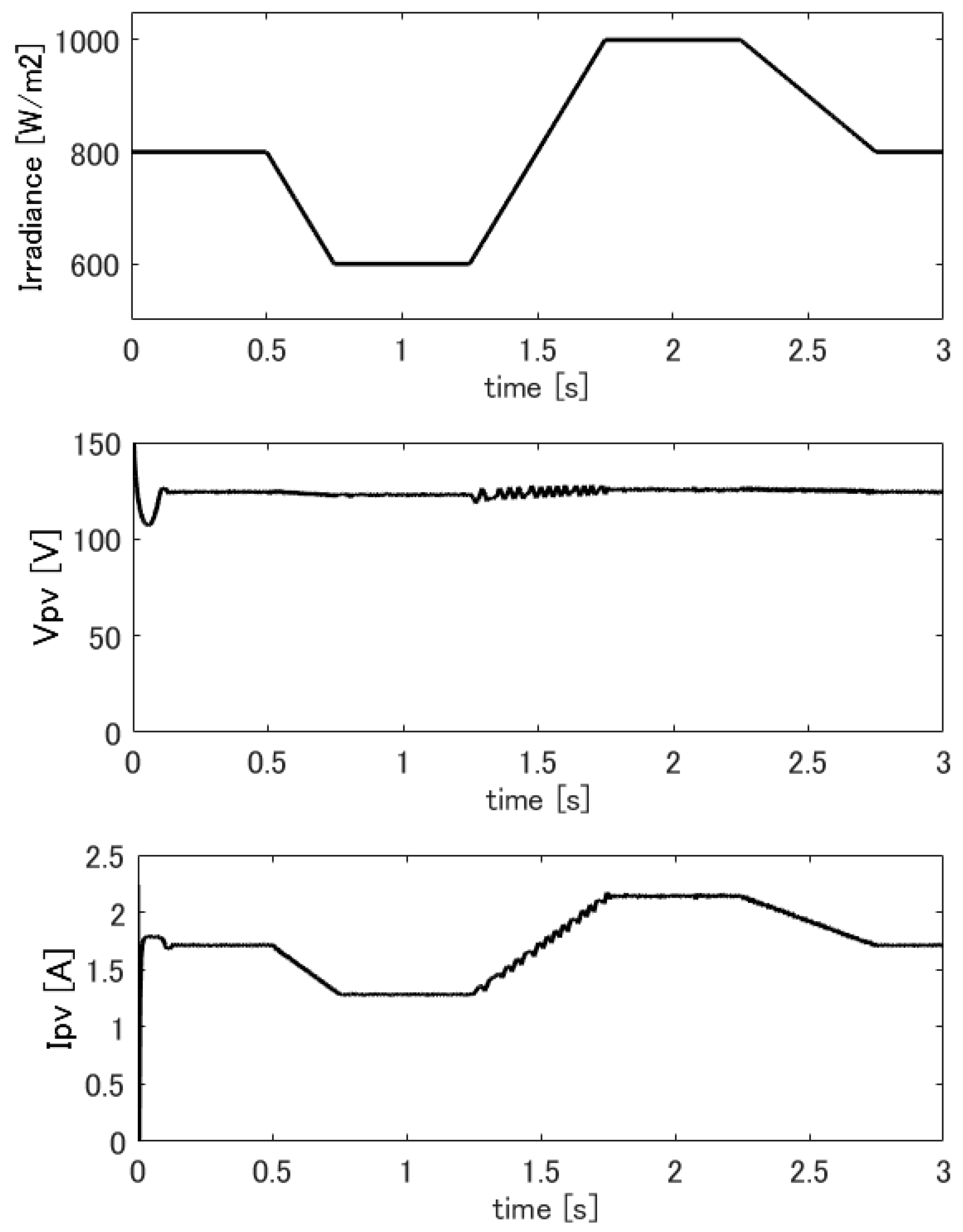
5. Experimental Results

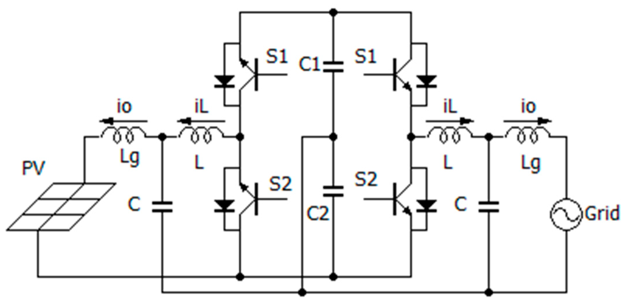
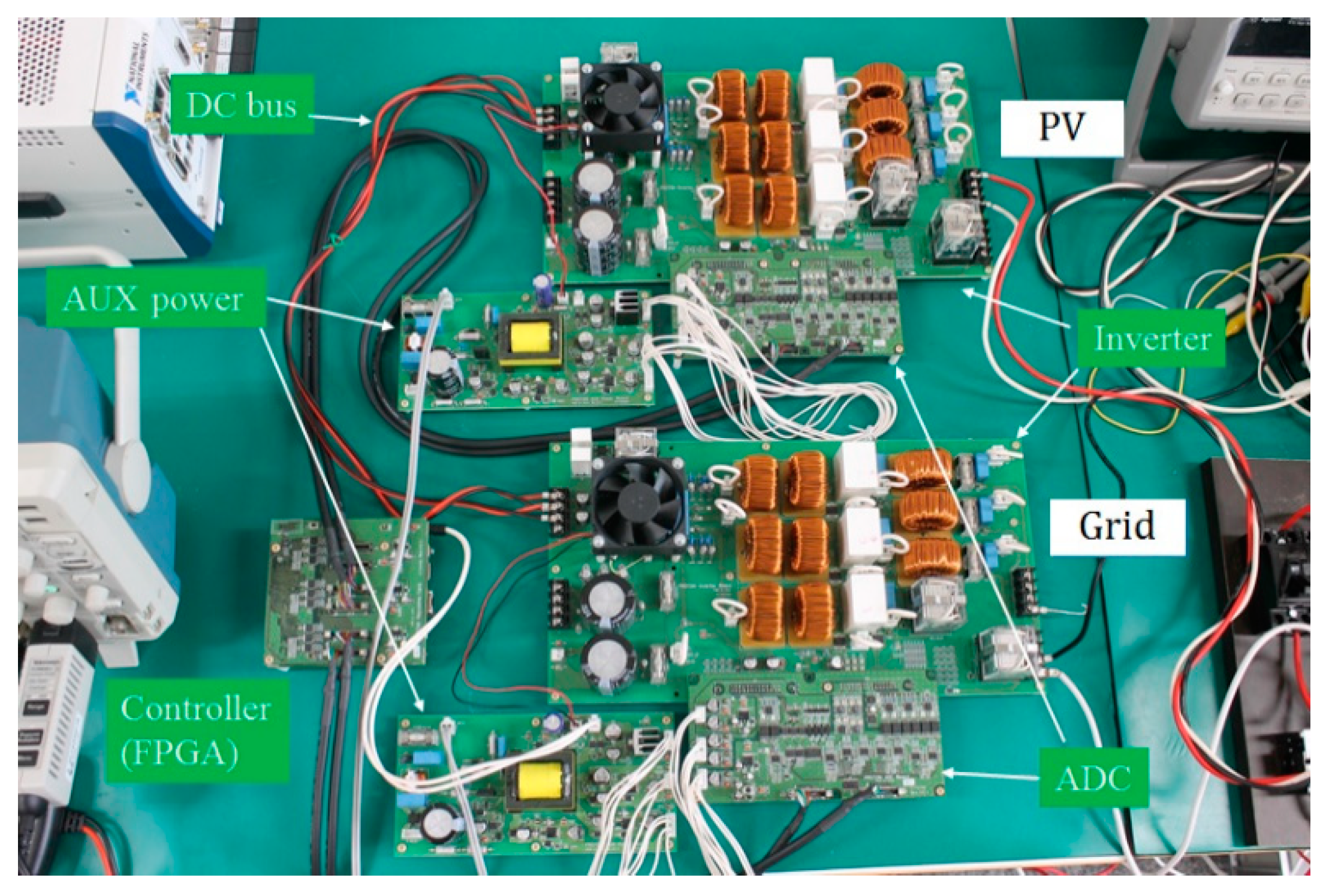
5.1. Grid-Connected PV System

Consider a DGR composed of two multi-functional inverters with a common DC bus, which is composed of electrolytic capacitors C 1 and C 2 as shown in Figure 8. The first inverter connects to a PV panel and another one connects to an AC power grid. The grid-connected inverter is controlled to maintain the voltages of capacitors C 1 and C 2 at a given constant value V d c _ r e f . The PV-connected inverter sends the power generated by the PV panel to the common DC bus, and the grid-connected inverter sends that power from the common DC bus to the grid.
Let v 1 and v 2 are the voltages of capacitors C 1 and C 2 . The grid has a voltage of v g . In this work, the grid-connected inverter is controlled by using the adaptive hysteresis current control presented in session 3 with the reference current is calculated as [18]:
i r e f ( k T ) = k t ( 2 V d c _ r e f ( v 1 ( k T ) + v 2 ( k T ) ) ) v g ( k T ) 2 V g + k b ( v 1 ( k T ) v 2 ( k T ) ) ,
where k t ,   k b > 0 are the control gains, which tune the speed of the response, V g is an effective value of the grid voltage v g .

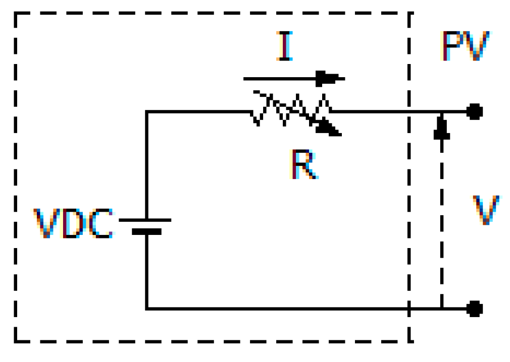
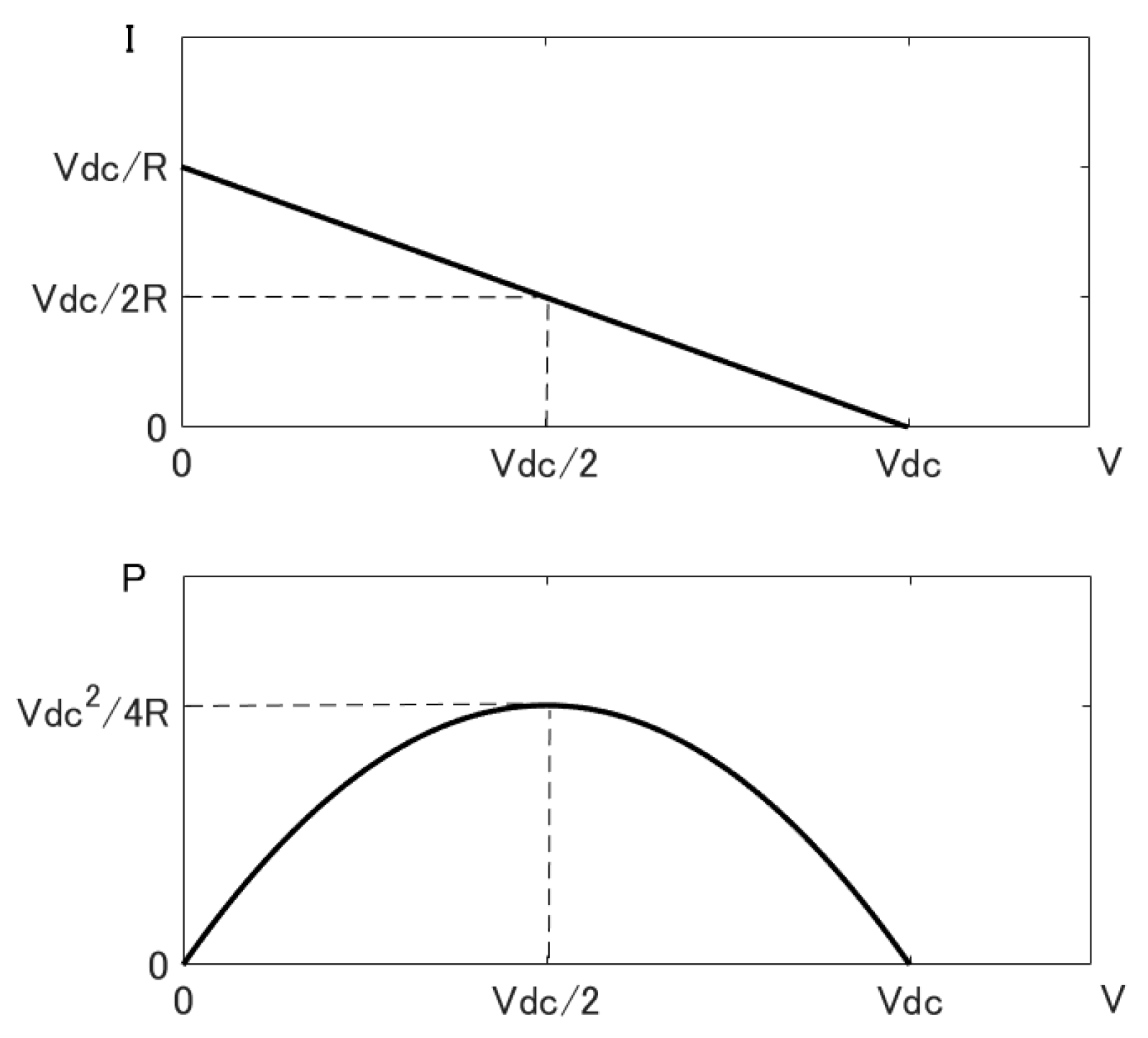
5.2. Simple Model for PV Panel

Due to space constraints of the laboratory, a simple electrical circuit composing of a DC power source and a variable resistor as shown in Figure 9 is used to emulate the PV panel. The voltage-current and voltage-power characteristics of this PV model are as below.
The output power P of this PV model is calculated as:
P = VI.
Using Kirchhoff’s rule for the circuit shown by Figure 9, we have:
VDC = V + RI.
Substituting Equation (28) into Equation (27), we can write the output power P as:
P = 1 R V ( V D C V ) .
The voltage-current and voltage-power characteristic curves of the PV model given by Equations (28) and (29) can be figured by Figure 10. The maximum power point can be determined as:
V max = V D C 2 ,
I max = V D C 2 R ,
P max = V D C 2 4 R .
In Figure 10, it can be seen that the value of the variable resistor R may change the voltage-power and voltage-current characteristics of the PV model. Thus, the variable resistor R can be used to emulate the variation of the solar irradiance. Although the PV model showed in Figure 9 emulates only the basic voltage-current and voltage-power characteristics of the PV panel, it is efficient for the purpose of evaluating the MPPT and SPPT algorithms for the PV control.

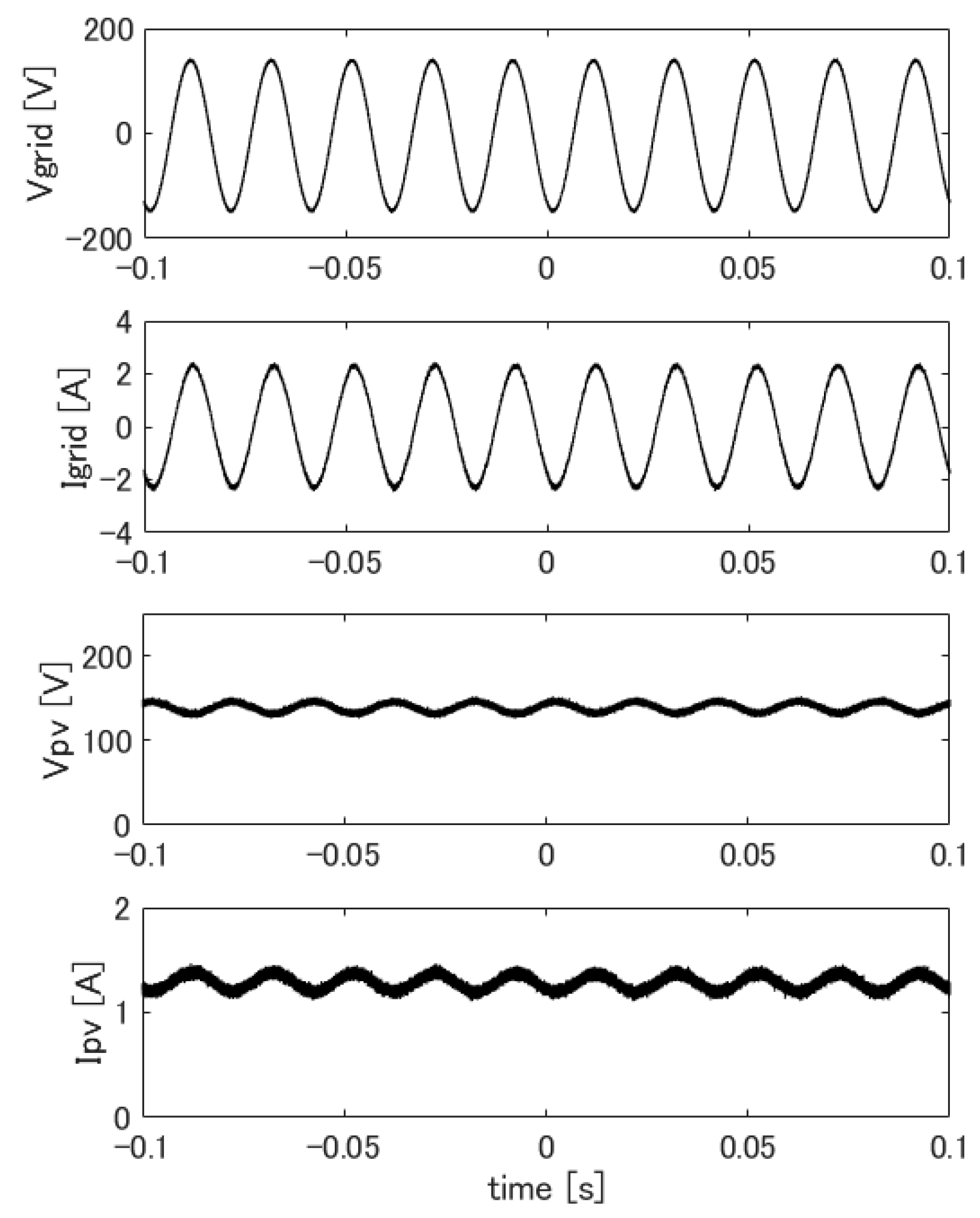
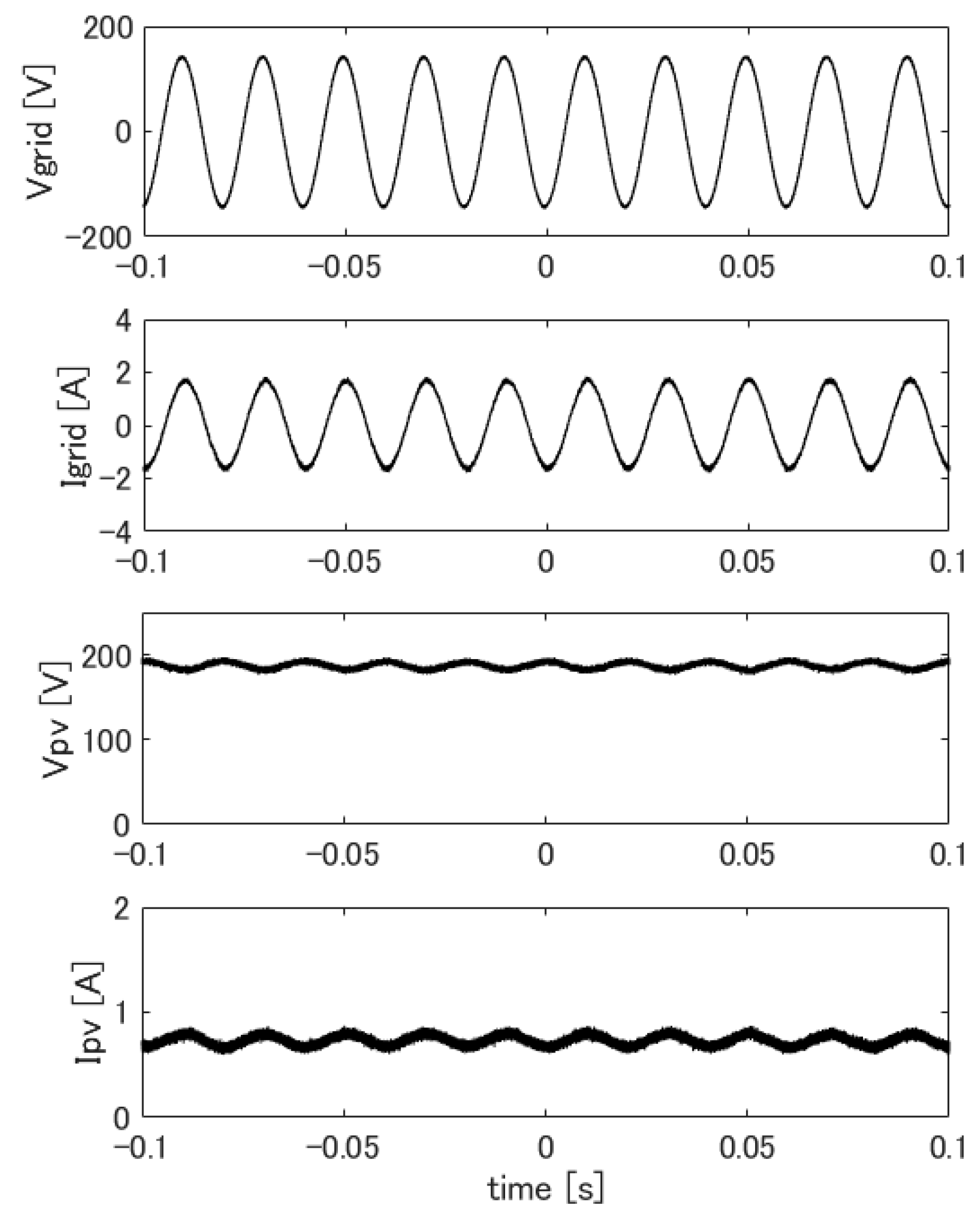
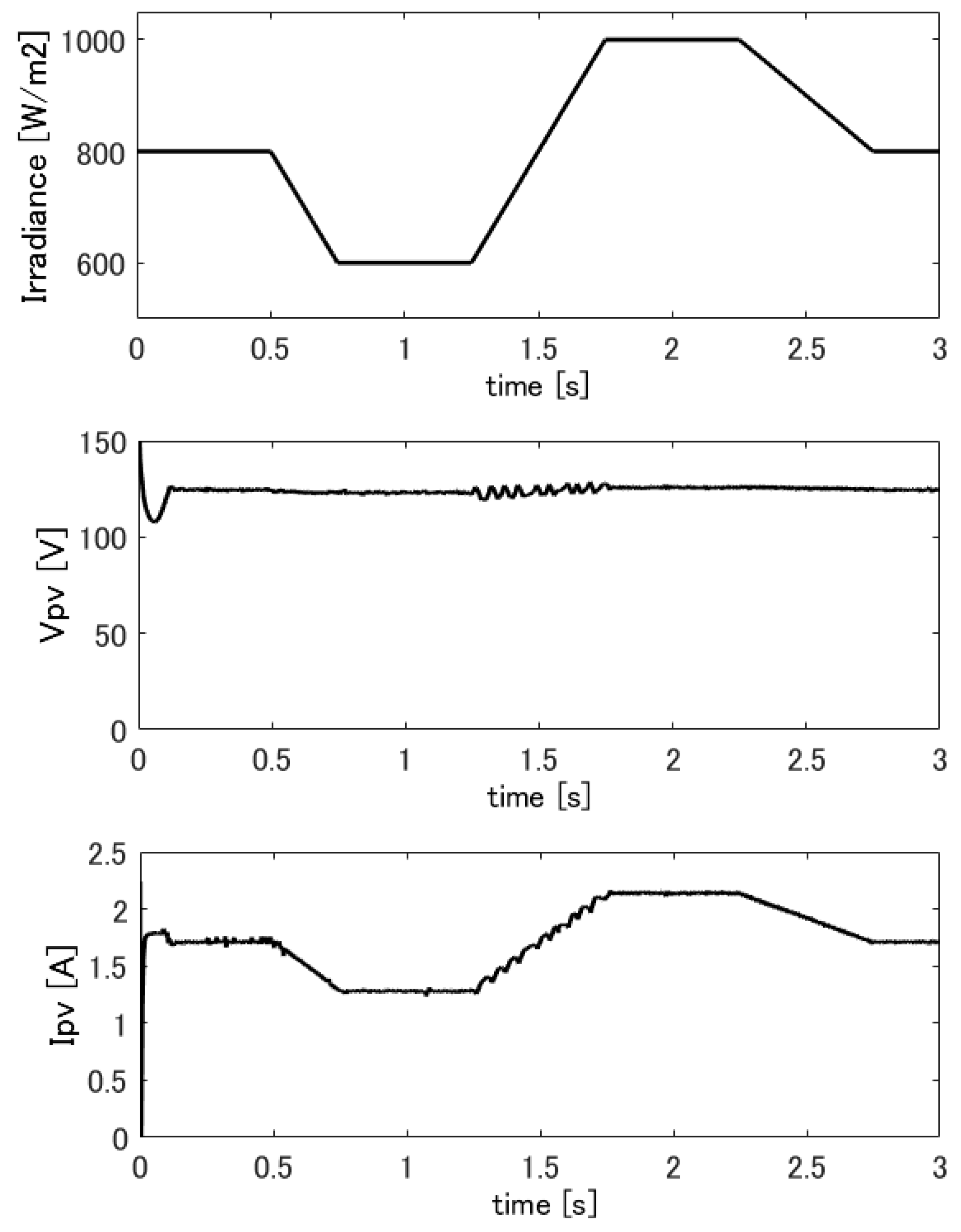
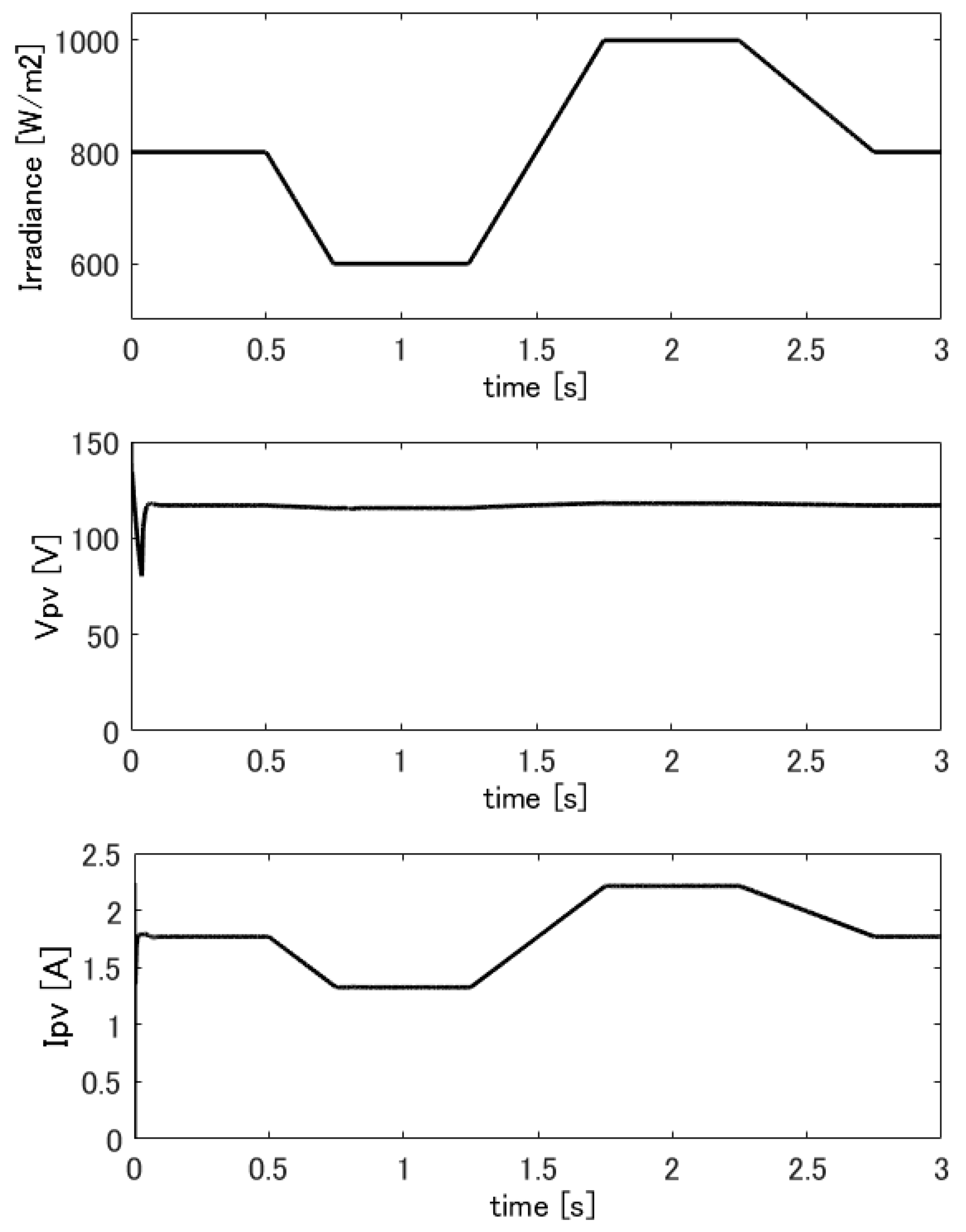
5.3. Experimental Results

The proposed control algorithm for the PV-connected inverter has been assessed by using a prototype of the DGR, which is composed of two multi-functional inverters connected by the circuit shown in Figure 8. The experimental setup is shown by Figure 11. Each inverter has a rated power of 300   W . The circuit parameters of the inverters are given by: L = 2.2 mH, Lg = 1.1 mH, and C = 6.8 µF. The reference voltage of the DC bus V d c _ r e f is set at 175 V. The analog/digital converter (ADC) has the sampling frequency of 4 MHz. The switching transistors in the inverter circuit are IGBT devices with the dead-time at 1.5 µ sec. The constant switching frequency in the adaptive hysteresis current control is at 20 kHz. The control algorithm is implemented on a FPGA board, which has a clock frequency of 160 MHz. The grid has an AC voltage of 100 V and frequency of 50 Hz. The DC power source of the PV model V D C in Figure 10 is at 250 V. The step-size δ i of the reference current is at 0.1 A.
Table 1 shows experimental result data for the MPPT control with various solar irradiances, which is emulated by the variable resistor in the PV model. The output power of the PV-connected inverter matches with the maximum power of the PV model calculated using Equation (32) almost exactly.
Table 2 shows experimental result for the same system controlled by SPPT algorithm with the specified power of P s = 150   W . The output power of the inverter is kept at the specified power P s regardless to the variation of the solar irradiance. Figure 12 shows the voltage and current responses of the grid-connected and PV-connected inverters controlled by the MPPT algorithm with the solar irradiance emulating resistor R at 80 W. Figure 13 shows the responses of the same inverter controlled by the SPPT algorithm. In all the tested cases including that for different value of R , the PV-connected inverter generates a power, which exactly matches the desired power. The grid-connected inverter sends the power generated from the PV-connected inverter to the grid and keeps the voltage of the common DC bus at constant. The voltage and current responses of the both inverters are stable for all tested cases.
Figure 14 and Figure 15 show the responses of the inverters with the MPPT control when the solar irradiance emulating resistor R changes from 60 W to 100 W and contrarily from 100 W to 60 W, respectively. The experimental results show that the proposed control algorithm yields responses, which are stable and adapt to the variation of the solar irradiance quickly.
Simulations have been carried out to compare the proposed MPPT algorithm using adaptive hysteresis current control with other common MPPT algorithms based on SPWM technique by using Matlab-Simulink. Figure 16, Figure 17, Figure 18 and Figure 19 shown the responses of the PV panel for the proposed MPPT, the perturb and observe (P&O) [20], and the incremental conductance (InC) [21], and fractional open-circuit voltage (FOCV) [22] algorithms, respectively. While the P&O and the InC algorithms yield unstable responses with oscillations when the irradiance changes, the proposed and FOCV algorithms give smooth and fast responses without oscillation. However, the proposed algorithm is simpler than the FOCV algorithm, which is based on complicated calculations using a PI regulator.

6. Conclusions

A new control algorithm for PV-connected inverters called Specified Power Point Tracking (SPPT) control has been proposed in addition to the conventional MPPT control. The PV system is controlled to generate the maximum power or a specified power depending on the electricity transactions. The control algorithm is based on high-speed FPGA-based digital adaptive hysteresis current control, which has a fast and stable response, and a simple structure compared with the conventional sine-triangle PWM method and can improve the disadvantages of the classical fixed band hysteresis current control on the varying switching frequency. The reference current is calculated such that the output power is maximized in the MPPT control or is maintained at a given value in the SPPT control. The hysteresis current control enables us to use the same multi-functional inverter hardware connecting to the PV, the grid, or the load in stand-alone system just by changing the calculation for the reference current. The experimental results show that the PV-connected inverter under the proposed control algorithm generates the desired power almost exactly with stable and fast response despite the varying solar irradiance. The simulation results show that the proposed MPPT control algorithm give better performance than the common MPPT algorithms such as P&O, InC, and FOCV. The proposed MPPT and SPPT control algorithm enables us to control of the PV system based on the electricity transactions receives from the electricity trading system. This operation method is expected to contribute to the improvement of the demand-supply balance problem, which is inhibiting the vast employment of renewable energy.

Author Contributions

T.N.-V., R.A., K.T. performed and discussed the research; T.N.-V. carried out the experiments, analyzed the data, and wrote the paper.

Funding

This research received no external funding.

Conflicts of Interest

The authors declare no conflict of interest.

References

  1. Kouro, S.; Leon, J.I.; Vinnikov, D.; Franquelo, L.G. Grid-Connected Photovoltaic Systems: An Overview of Recent Research and Emerging PV Converter Technology. IEEE Ind. Electron. Mag. 2015, 9, 47–61. [Google Scholar] [CrossRef]
  2. Algarín, C.R.; Giraldo, J.T.; Álvarez, O.R. Fuzzy Logic Based MPPT Controller for a PV System. Energies 2017, 10, 2036. [Google Scholar] [CrossRef]
  3. Islam, H.; Mekhilef, S.; Shah, N.B.M.; Soon, T.K.; Seyedmahmousian, M.; Horan, B.; Stojcevski, A. Performance Evaluation of Maximum Power Point Tracking Approaches and Photovoltaic Systems. Energies 2018, 11, 365. [Google Scholar] [CrossRef]
  4. Khayyer, P.; Özgüner, Ü. Decentralized Control of Large-Scale Storage-Based Renewable Energy Systems. IEEE Trans. Smart Grid 2014, 5, 1300–1307. [Google Scholar] [CrossRef]
  5. Marwali, M.N.; Dai, M.; Keyhani, A. Robust stability analysis of voltage and current control for distributed generation systems. IEEE Trans. Energy Convers. 2006, 21, 516–526. [Google Scholar] [CrossRef]
  6. Yamaya, H.; Ohigashi, T.; Matsukawa, H.; Kaizuka, I.; Ikki, O. PV market in Japan and impacts of grid constriction. In Proceedings of the IEEE 42nd Photovoltaic Specialist Conference (PVSC), New Orleans, LA, USA, 14–19 June 2015; pp. 1–6. [Google Scholar]
  7. Abe, R.; Taoka, H.; McQuilkin, D. Digital Grid: Communicative Electrical Grids of the Future. IEEE Trans. Smart Grid 2011, 2, 399–410. [Google Scholar] [CrossRef] [Green Version]
  8. Irwin, J.D. Control in Power Electronics: Selected Problems, 1st ed.; Academic Press: New York, NY, USA, 2002. [Google Scholar]
  9. Vázquez, G.; Rodriguez, P.; Ordoñez, R.; Kerekes, T.; Teodorescu, R. Adaptive hysteresis band current control for transformerless single-phase PV inverters. In Proceedings of the 35th Annual Conference of IEEE Industrial Electronics, Porto, Portugal, 3–5 November 2009; pp. 173–177. [Google Scholar]
  10. Kumar, N.; Hussain, I.; Singh, B.; Panigrahi, B.K. Normal Harmonic Search Algorithm Based MPPT for Solar PV System and Integrated with Grid using Reduced Sensor Approach and PNKLMS Algorithm. IEEE Trans. Ind. Appl. 2018. [Google Scholar] [CrossRef]
  11. Bhatnagar, P.; Nema, R.K. A maximum power point tracking algorithm for photovoltaic systems using bang-bang controller. J. Renew. Sustain. Energy 2014, 6, 053126. [Google Scholar] [CrossRef]
  12. Buso, S.; Malesani, L.; Mattavelli, P. Comparison of current control techniques for active filter applications. IEEE Trans. Ind. Electron. 1998, 45, 722–729. [Google Scholar] [CrossRef] [Green Version]
  13. Attaianese, C.; Monaco, M.D.; Tomasso, G. High Performance Digital Hysteresis Control for Single Source Cascaded Inverters. IEEE Trans. Ind. Inform. 2013, 9, 620–629. [Google Scholar] [CrossRef]
  14. Nguyen-Van, T.; Abe, R.; Tanaka, K. Stability of FPGA Based Emulator for Half-bridge Inverters Operated in Stand-alone and Grid-connected Modes. IEEE Access 2018, 6, 3603–3610. [Google Scholar] [CrossRef]
  15. Schaefer, M.; Hofmann, M.; Raab, S.; Ackva, A. FPGA Based Control of an Three Level Neutral Point Clamped Inverter. In Proceedings of the Europe 2017 International Exhibition and Conference for Power Electronics, Intelligent Motion, Renewable Energy and Energy Management, Nuremberg, Germany, 16–18 May 2017; pp. 1–6. [Google Scholar]
  16. Nguyen-Van, T.; Abe, R.; Tanaka, K. A Digital Hysteresis Current Control for Half-Bridge Inverters with Constrained Switching Frequency. Energies 2017, 10, 1610. [Google Scholar] [CrossRef]
  17. Devaraj, D.; Sakthivel, S.; Punitha, K. Modeling of photovoltaic array and simulation of adaptive hysteresis current controlled inverter for solar application. In Proceedings of the 3rd International Conference on Electronics Computer Technology, Kanyakumari, India, 8–10 April 2011; pp. 302–306. [Google Scholar]
  18. Nguyen-Van, T.; Abe, R.; Tanaka, K. Digital Adaptive Hysteresis Current Control for Multi-functional Half-bridge Inverters. IEEE Trans. Power Electron. Under Reviewed.
  19. Takagi, S. The Japanese equity market: Past and present. J. Bank. Fin. 1989, 13, 537–570. [Google Scholar] [CrossRef]
  20. Nedumgatt, J.J.; Jayakrishnan, K.B.; Umashankar, S.; Vijayakumar, D.; Kothari, D.P. Perturb and observe MPPT algorithm for solar PV systems-modeling and simulation. In Proceedings of the 2011 Annual IEEE India Conference, Hyderabad, India, 16–18 December 2011; pp. 1–6. [Google Scholar]
  21. Safari, A.; Mekhilef, S. Incremental conductance MPPT method for PV systems. In Proceedings of the 24th Canadian Conference on Electrical and Computer Engineering (CCECE), Niagara Falls, ON, Canada, 8–11 May 2011; pp. 345–347. [Google Scholar]
  22. Ahmad, J. A fractional open circuit voltage based maximum power point tracker for photovoltaic arrays. In Proceedings of the 2nd International Conference on Software Technology and Engineering, San Juan, PR, USA, 3–5 October 2010; pp. V1-247–V1-250. [Google Scholar]
Figure 1. Digital grid system with electricity trading using block-chain.
Energies 11 02075 g001
Figure 2. Structure of the digital grid router.
Energies 11 02075 g002
Figure 3. Single-phase half-bridge inverter circuit.
Energies 11 02075 g003
Figure 4. Adaptive hysteresis current band.
Energies 11 02075 g004
Figure 5. PV connected inverter circuit.
Energies 11 02075 g005
Figure 6. Characteristic PV and MPPT control curves.
Energies 11 02075 g006
Figure 7. Characteristic PV and SPPT control curves.
Energies 11 02075 g007
Figure 8. Grid-connected PV panel circuit.
Energies 11 02075 g008
Figure 9. Electrical model for PV panel.
Energies 11 02075 g009
Figure 10. Voltage-current and voltage-power characteristic curves of the PV model.
Energies 11 02075 g010
Figure 11. Experimental DGR circuit.
Energies 11 02075 g011
Figure 12. Responses of grid-connected and PV-connected inverters under MPPT control with R = 80   Ω .
Energies 11 02075 g012
Figure 13. Responses of grid-connected and PV-connected inverters under SPPT control with R = 80   Ω .
Energies 11 02075 g013
Figure 14. Responses of grid-connected and PV-connected inverters under MPPT control when the resistor R changes from 60 W to 100 W.
Energies 11 02075 g014
Figure 15. Responses of grid-connected and PV-connected inverters under MPPT control when the resistor R changes from 100 W to 60 W.
Energies 11 02075 g015
Figure 16. Responses of the proposed MPPT control with the varying irradiance.
Energies 11 02075 g016
Figure 17. Responses of the P&O control with the varying irradiance.
Energies 11 02075 g017
Figure 18. Responses of the InC control with the varying irradiance.
Energies 11 02075 g018
Figure 19. Responses of the FOCV control with the varying irradiance.
Energies 11 02075 g019
Table 1. Experimental result data for MPPT control.
Resistor R   [ Ω ] Measured Current I   [ A ] Measured Voltage V   [ V ] Measured Power P   [ W ] Calculated Power P   [ W ]
1001.19131155156
801.38140194195
601.87136254260
Table 2. Experimental result data for SPPT control.
Resistor R   [ Ω ] Measured Current I   [ A ] Measured Voltage V   [ V ] Measured Power P   [ W ] Specified Power P s   [ W ]
1000.9161145150
800.76191144
600.72208148

