1. Introduction
In building sustainability designs, three major assessments are considered: thermal performance, energy efficiency, and water conservation. The major factors affecting the thermal performance of buildings are basically related to the building architecture design, such as: the roof type (e.g., gable or flat), the roof orientation, shading from adjacent objects, building materials (e.g., double brick or brick veneer walls), insulation, and glazing. In cold-weather zones, shading the building’s façade or roof may reduce the heat gain of the building and increase the heating load during the cold season. On the other hand, in hot- or warm-weather zones, shading a building’s façade and/or the roof will reduce the cooling load and increase the building’s thermal performance. The effect of PV panels’ shading on heat transfer through a flat roof building was simulated and tested by [
1]. Part of the roof was covered with PV panels and a ceiling temperature measurement was conducted to verify and validate the mathematical heat transfer model. The study showed that the reduction in cooling load due to the shaded roof by a PV panel is more than the reduction in heating load which enhances the annual net energy balance of the building by 4%. Another work by Kotak et al. [
2] studied the effect of rooftop PV panels on the cooling load of a flat roof house using a computer simulation. The results show that there is a significant decrease in the cooling load due to the roof area shaded by PV panels. However, the heat transfer model in this study did not consider insulation to the roof or ceiling below the PV panels. A simulation model has been developed to evaluate cooling load and heat gain components through an inclined PV roof structure [
3]. It was found that installing a PV rooftop may reduce the cooling load by 35% for the roof design considered in that work (a gable roof without a significant insulation layer). The air gap between PV panels and roof surface as well as the roof inclination angle were found to be major factors affecting the thermal and energy performance of the building. A thermal model for an inclined PV panel mounted on a ventilated structure was developed by [
4]. This model evaluated the total heat loss coefficient of the panel surface and predicted its temperature response time. The study, which was validated by an experimental test, showed that heat loss by radiation between the panel surface and the sky is very low compared to the convective heat loss and it can be neglected in the thermal model.
Roof orientation and inclination has a significant effect on solar heat gain as well as the power generated by the rooftop PV system. A review of the optimum tilt and azimuth angles of a rooftop PV panel was conducted considering climate conditions and surrounding obstacles [
5]. The study concluded that the optimum tilt angle is closer to the location latitude if the clearness index value is constant during the year. It was observed that the optimum tilt and azimuth angle of the PV panel was influenced significantly by the surrounding obstacles, such as adjacent buildings. Another analytical study was conducted on a larger scale system (50 kW output) and concluded that the maximum PV panel yield occurs when the PV panel tilt angle is about 1.5° less than the site latitude angle [
6]. The impact of roof design on the output of an urban building solar energy system (hot water of electricity) was studied by [
7]. Three types of roof designs were considered in this study: flat, gabled, and lean-to-roof. The results showed that the contribution of solar energy to covering the demand of hot water and electricity of a building is higher in case of the flat roof than the gabled roof design. This is because, in the case of the gabled roof, there will be less irradiation on the side of the roof opposing the sun. The optimal configuration in the roof of the housing unit was implemented to increase the solar potential of the building’s integrated PV/Thermal system [
8]. The effect of the roof configuration shape on energy performance in terms of heating and cooling load was investigated by computer modelling. It was found that the effect of different roof designs on heating and cooling loads is less than 5%. However, it was concluded that the integration of a PV/thermal system in the roof design of different orientations enables the spread of peak electricity timing over longer operation hours. This work did not show how to overcome the complexity in the PV rooftop installation associated with a folded roof design. A breakdown of heat loss and heat gain rate by a house envelope was investigated by [
9]. They found that the highest amount of heat loss rate takes place in the ceiling/roof and represents 62% of the total heat loss from the building envelope. The heat gain rate by the ceiling/roof was found to be significant and represents 33.5% of the total heat gain rate by the building envelope.
The literature review of rooftop PV systems does not show significant analysis of designs that have a roof space with insulation. Since the majority of roof designs in Australia have roof space, research work in this respect was found to be necessary to find the effect of the roof shaded area by PV panels on the energy efficiency of the dwellings. This paper studies the effect of shading developed by rooftop PV panels on the cooling and heating load. The proposed analysis correlates the electric energy generated from the PV panels to the heating and cooling load of a dwelling with a roof space design at different roof orientation angles.
2. Thermal Modelling of the Roof
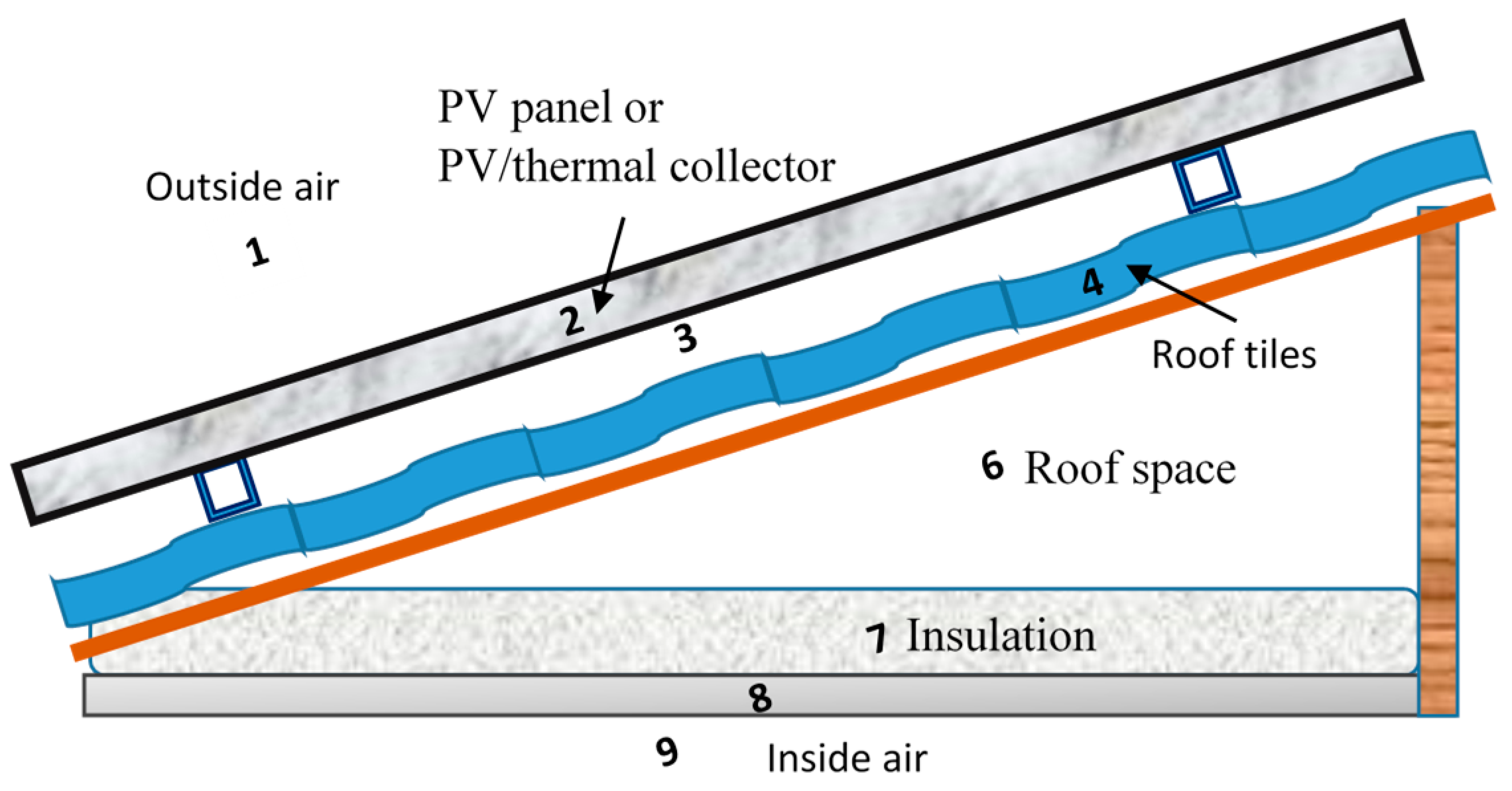
The type of roof considered in this study is a gabled roof with a PV panel arrangement similar to the design shown in
Figure 1. Thermal modelling for this design can be developed by considering the thermal resistance of different components between the external air and the inner space of the dwelling. There are nine major thermal resistances identified in this roof design, these are:
- R1
Thermal resistance of external air adjacent to the roof surface.
- R2
Thermal resistance of PV panel or PV/thermal collector material.
- R3
Thermal resistance of the air space between a panel and the roof surface.
- R4
Thermal resistance of roof material (tiles or metal sheet).
- R5
Thermal resistance of the air gap between the roof material and a sarking sheet.
- R6
Thermal resistance of a gabled roof space.
- R7
Thermal resistance of the insulation above the ceiling.
- R8
Thermal resistance of ceiling material.
- R9
Thermal resistance of the inner space air adjacent to the ceiling.
Some of these thermal resistances are quite standard and can be selected from tables based on the roof type and roof design, such as
R4,
R5,
R6,
R7,
R8, and
R9 [
10]. The thermal resistance
R2 can be calculated by adopting the PV module thermal conductivity given by [
3,
4]. The remaining thermal resistances
R1 and
R3 are affected by surrounding conditions and can be calculated by using conventional heat transfer formulas [
11]. To find
R1, two components of heat transfer coefficients are considered: the heat transfer coefficient by convection of the ambient air, and the heat transfer coefficient by radiation with sky temperature,
where
hc1 and
hr1 are the heat transfer coefficients by convection and radiation, respectively, and can be found by [
11],
where
Nu1
is the Nusselt number,
Or,
where
Pr is the Prandtl number,
Re is the Reynolds number,
Ka is the thermal conductivity of air (W/m
2·°C),
L is the PV array length (m), and
Ra is the Rayleigh number found by [
10]
where
v = kinematic viscosity of the fluid (m2/s)
Trs = temperature of the roof surface,
βt = Thermal expansion = 1/Ta [K−1],
Tpb = Temperature of the PV panel’s back surface found by [
3],
and,
where
Tpv is the PV surface temperature given by [
12] and is found by,
where
Irr is the solar irradiation (W/m
2) and
Ta is the ambient temperature (K).
where
εpv = Emissivity of the PV panel’s upper surface,
σ = Stefan–Boltzmann constant (5.670367 × 10⁻⁸ W·m−2·K−4),
Tsky = Sky temperature (K) found by [
13],
R2 can be evaluated by knowing the PV or PV/thermal panel thickness (
x) and thermal conductivity (
k), where
To find
R3, a similar approach to
R1 is considered using the heat transfer coefficient by natural convection in the air gap
and the heat transfer coefficient by radiation between the roof surface and the PV panel’s back surface
, where
where
hc3 is the heat transfer coefficient by convection for open-ended space given by [
3]
where
La is the length of the air gap (m) between the roof surface and the solar panel,
xa is the air gap height (m), and
β is the roof surface angle.
hr3 is found from the heat radiation equation between two parallel surfaces [
11], where
where,
εpb and
εrs are the emissivity of the PV panel’s back surface and the emissivity of the roof surface, respectively.
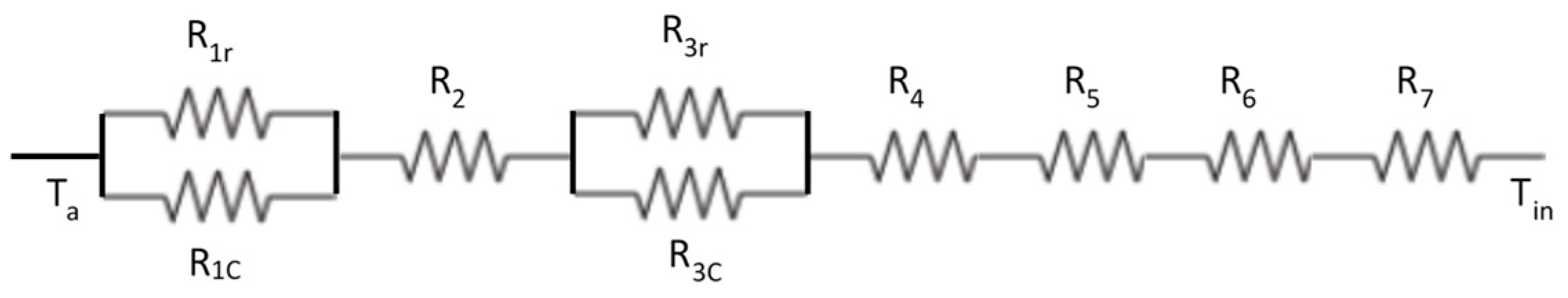
The thermal model of the rooftop PV design presented by the thermal resistances
R1 to
R9 shown in
Figure 2 and their associated Equations (1)–(13) were used to find out the effect of ambient temperature, optimum insulation size, and solar irradiation on heat transfer through a gabled and a flat roof dwelling. This design was compared with an uncovered roof design by eliminating
R2 and
R3 from the heat transfer model as well as adjusting Equation (7) to address the roof tile temperature
Trs rather than the PV surface temperature
TPV.
3. Thermal Analysis of the Roof System
The engineering equation solver package (EES) [
14] was used to investigate the most significant thermal resistances that affect heat transfer through the proposed roof design. The value of these thermal resistances is given in
Table 1. It is clearly shown that the optimum roof insulation
R7 (4 m
2·°C/W) is greater than the total of the other roof components’ thermal resistance, which was found to be in the range of 1.05–2.01 m
2·°C/W. Since
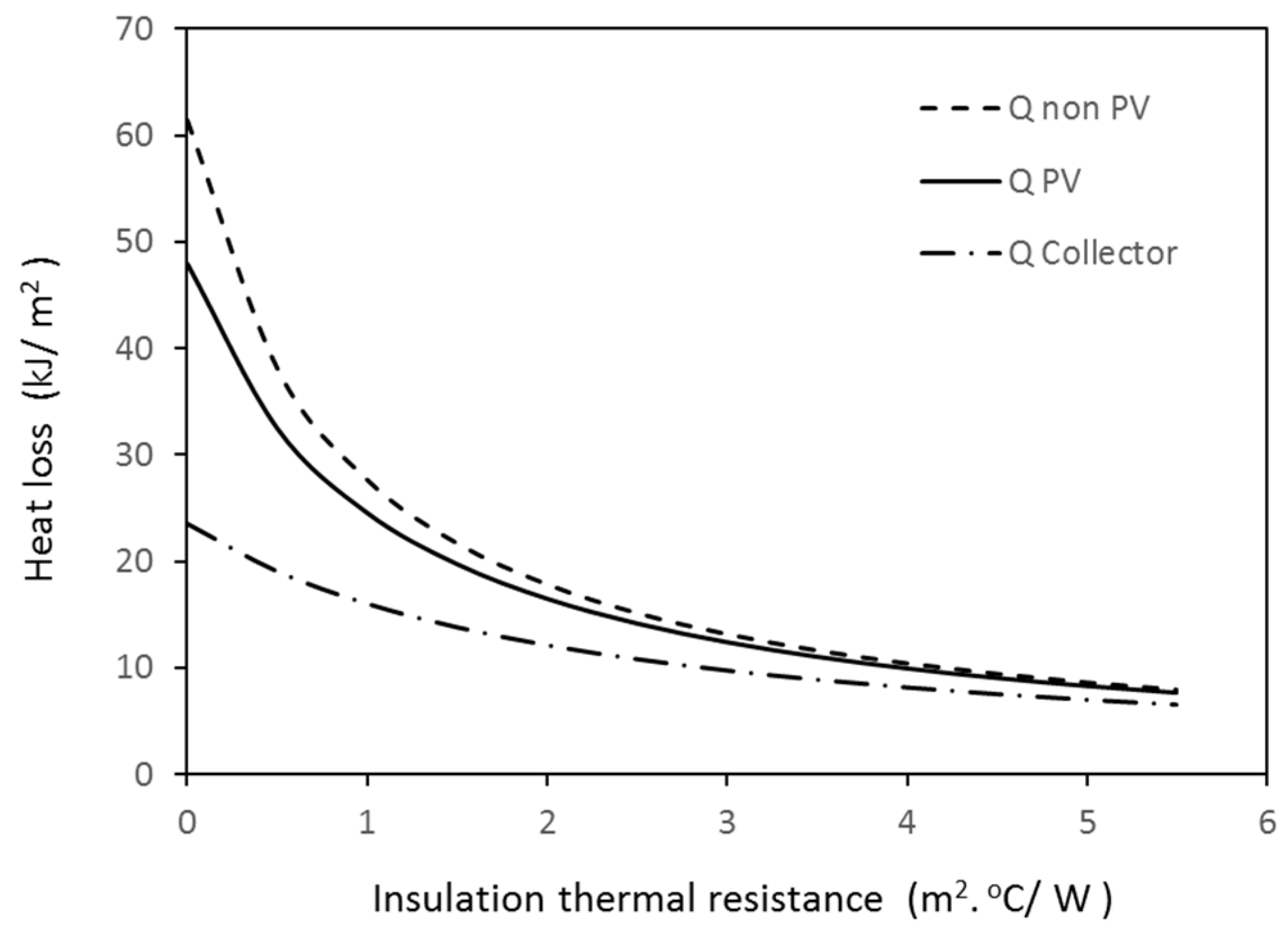
R7 is the major thermal resistance in the roof design of this study, it was important to investigate its effect on the heating and cooling load of a dwelling.
Figure 3 shows the effect of increasing
R7 on heat gain from a PV rooftop and a non-PV roof design. It is worthwhile to mention here that the commercial thermal resistance of insulation
R7 is represented by a value next to the symbol
R, i.e.,
R1 means that the thermal resistance of the insulation equals 1 m
2·°C/W,
R2 means that the thermal resistance of the insulation equals 2 m
2·°C/W, … etc.
The difference in heat loss from the roof between both designs decreases as the value of insulation increases up to a value of
R7 equal to 4 m
2·°C/W where the difference in heat loss starts to be negligible. The other finding from
Figure 3 is that the size of insulation (4 m
2·°C/W) represents the optimum limit as, after this size, the heat loss tends to be almost constant and adding extra insulation becomes unfeasible. This size of insulation is considered to be standard in modern building designs to achieve the maximum energy efficiency of dwellings.
To investigate the effect of using different types of rooftop solar energy systems, such as a solar thermal collector,
R2 of Equation (10) is replaced by the thermal resistance of the thermal collector. This resistance is related mainly to the insulation at the collector’s back side [
15], which was found to be equal to 1.1 (m
2 ·°C/W) [
15]. This value of
R2 is used in the roof thermal model described in Equations (1)–(13) to find the heat loss from a roof covered by a PV/thermal collector and the results are presented in
Figure 3. The results show that the heat loss from the roof covered by the PV/thermal collector is less than that from the roof covered by a PV panel alone. However, the difference between both cases becomes negligible at a ceiling insulation greater than 4 m
2·°C/W.
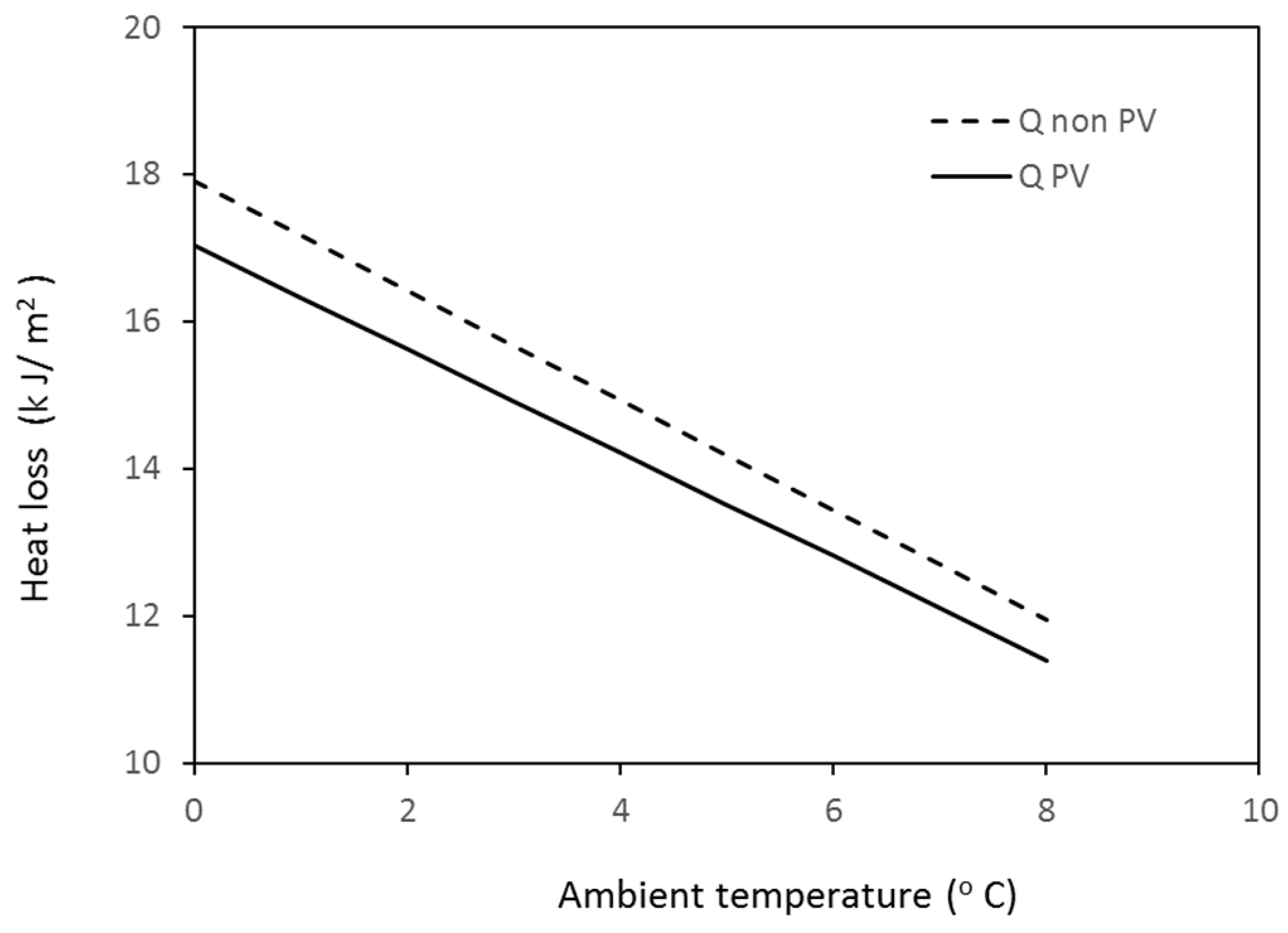
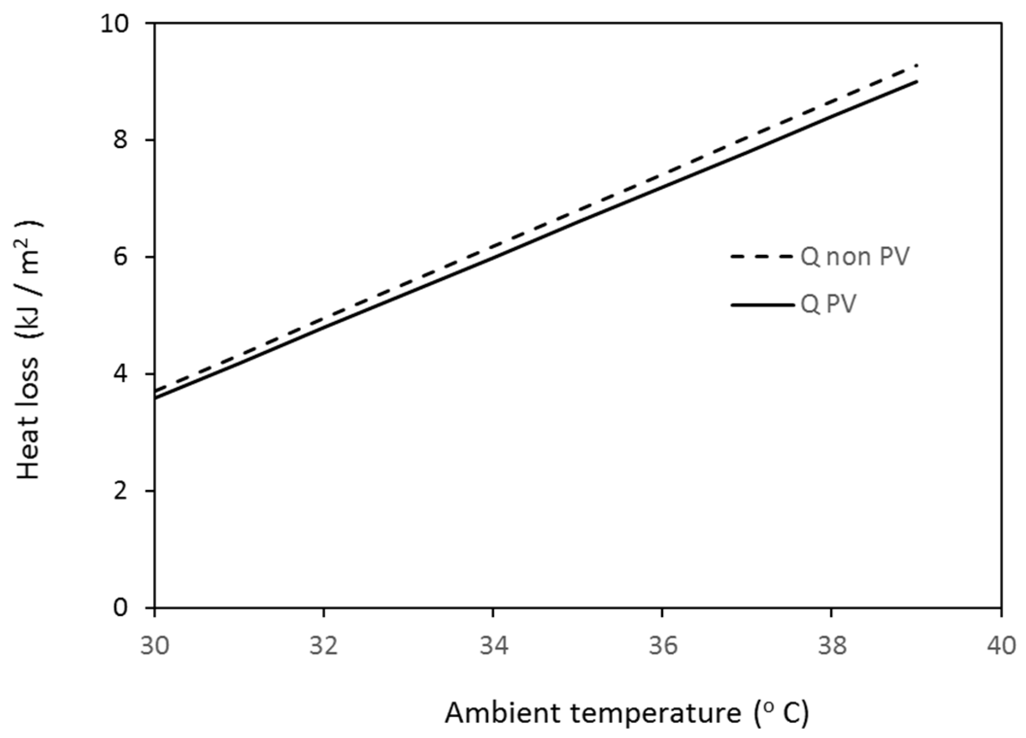
Further investigation of the effect of ambient temperature on heat transfer through the roof is conducted at constant irradiation (500 W/m
2), an average wind speed of 3 m/s, and an
R7 value equal to 4 m
2·°C/W. The results are shown in
Figure 4 and
Figure 5 for winter and summer ambient temperatures. These figures show that the difference in heat loss or heat gain between the PV roof and the non-PV roof is quite small and it is in the range of 3–4.5%.
4. Transient Analysis of Roof System Heating and Cooling Load
An annual performance analysis was conducted to evaluate the effect of covering the gabled roof by PV panels on the total heating and cooling load (
Qhc) of a dwelling. The benchmark software “AccuRate sustainability” [
16] for house energy ratings in Australia was used to perform energy modelling of a single-story, double-brick dwelling. The total floor area of the dwelling adopted in this study is 84 m
2 divided into a 74 m
2 conditioned area and a 10 m
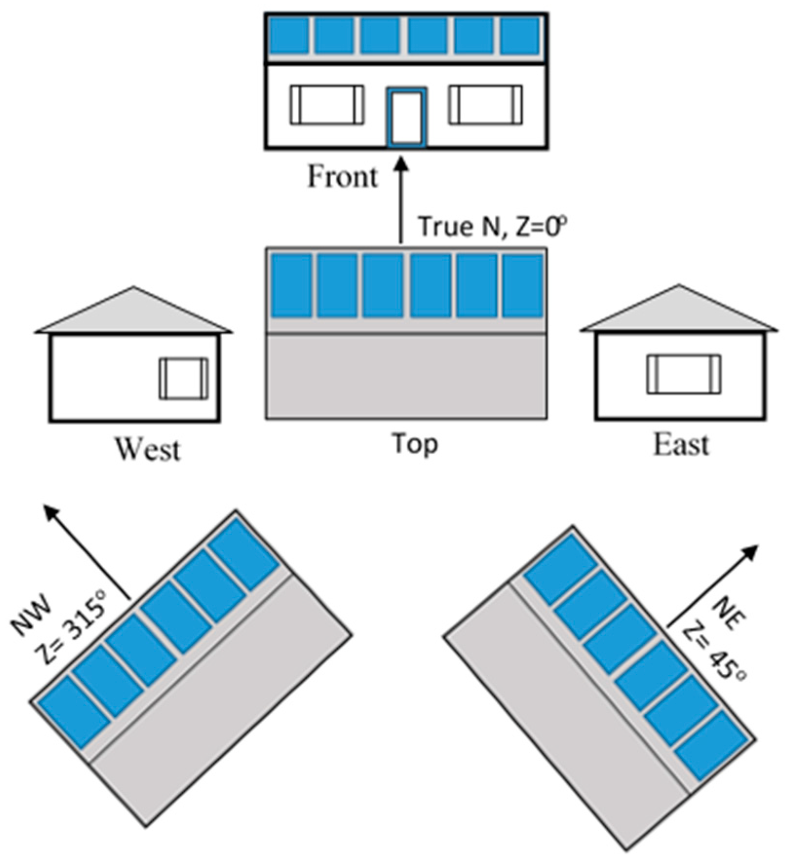
2 unconditioned area. The glazing to wall ratio of each dwelling side is: 18.5% N, 15.8% E, 11.9% W, and 10% S. The roof inclination of this dwelling is 22° following the Australian standard [
17] and consists of the same parts shown in
Figure 1. The northern side of the roof (facing the sun) was assumed to be fully covered by PV panels. The energy rating analysis was conducted on different dwelling orientations and different roof azimuth angles (Z): 0° N, 45° NE, 90° E, 270° W, and 315° NW with a PV arrangement similar to
Figure 6. The energy rating simulation was conducted twice for each dwelling orientation, once with the roof covered by PV panels and another run without PV panels. To simulate the roof shaded by a PV panel, another layer with a similar thermal conductivity and air gap was added to the construction option of “AccuRate”. The effect of roof insulation on the annual heating and cooling load of the prescribed dwelling was conducted for two types of roof: a gabled roof design and a flat roof design. The aim of this analysis is to investigate the effect of transient weather conditions on the heat transfer through a roof covered by PV panels.
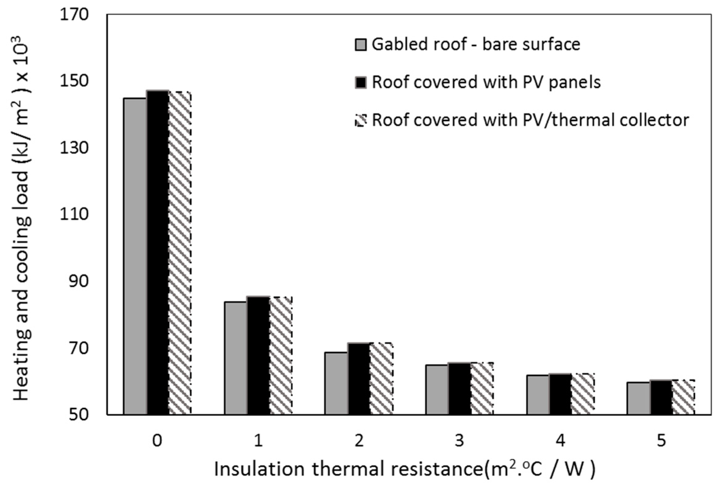
The effect of roof insulation on the annual (
Qhc) load of the dwelling was estimated in MJ per square metre of roof floor area and the results are presented in
Figure 7. The annual heating and cooling load is estimated by AccuRate, which considers the thermal loss from different parts of dwellings, including the roof, walls, floors, and windows. The trend of the results is quite similar to what was shown in
Figure 3 where the optimum insulation size was found to be about 4 m
2·°C/W. At this size of insulation, the type of roof design (gabled or flat) does not change the total heating and cooling load significantly. This finding leads to the conclusion that adding new modules to the external surface of the roof, such as PV panels, will not have a significant effect on the total (
Qhc) load if roof insulation is within the optimum range. It is clear from
Figure 7 that the gabled roof has less (
Qhc) load than the flat roof for insulation thermal resistance values less than 2.5. This is because the thermal resistance of the gabled roof’s air space becomes dominant at low
R values of insulation.
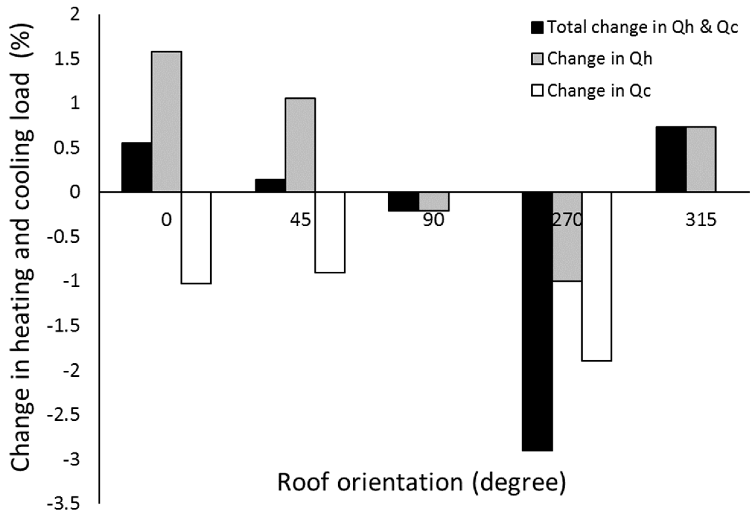
It is worthwhile to mention here that the percentage change in
Qhc due to rooftop PV panel shading may have a positive or negative impact on the energy consumption by air-conditioning. The annual percentage of change in
Qhc due to PV panel shading was estimated at different roof orientations and is shown in
Figure 8. In some roof orientations, such as the West roof (where the azimuth angle is 270°), the percentage of decrease in
Qhc is 3%, i.e., adding a PV panel to the roof will improve the dwelling’s thermal efficiency due to the reduction in heating and cooling loads. It can be concluded from
Figure 8 that the percentage of increase in
Qhc in general is very small (between 0.15 and 0.7%) at the roof azimuth angles of 0, 45, and 315° due to the increase in heating load at these roof orientations. In general,
Figure 8 shows that the percentage of change in
Qhc is very small and it is in the range of −3 to 0.74%.
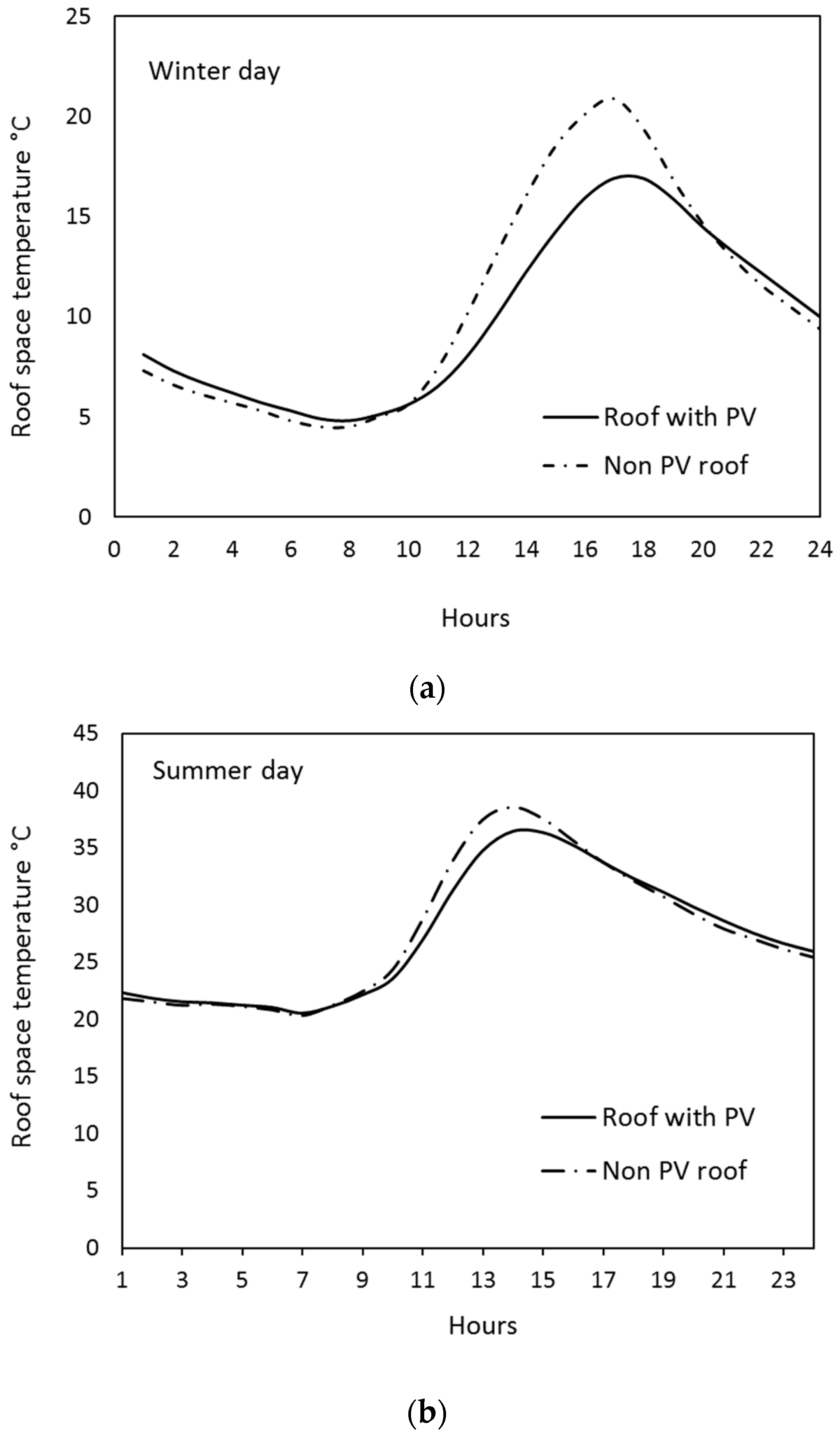
The low percentage of change in
Qhc can be justified by examining the yearly change of roof space temperature in PV roof and non-PV roof cases by using ACCURATE with the non-modelling option. The results show that the hourly temperature difference between both cases increases in the afternoon hours and approaches to zero during no sunlight hours. The temperature difference is affected also by the seasons due to the change in ambient temperature. Two extreme days shown in
Figure 9a,b were selected to display the roof space temperature profile in winter and summer. It is clear that the variance in the roof space temperature between the two types of roof increases in winter, by about 31%, and by 6% in summer in the afternoon hours as shown in
Figure 9a,b. However, since this increase occurs only in a limited number of hours of the year, the change of heat transfer rate and, therefore, the change in the total thermal load is not significant as presented in
Figure 8.
The Effect of Different Rooftop Solar Systems on the Annual Heating and Cooling Load
The effect of shading developed by three types of roof—a bare surface roof, a roof surface covered with PV panels, and a roof surface covered with a PV/thermal collector—on the annual heating and cooling load of the dwelling was examined. The PV/thermal collector is mainly used to provide dual output (thermal and electrical) and to improve PV panel efficiency due to cooling by the collector’s working fluid. Different designs of PV/thermal collectors were found in the literature, such as:
- -
a PV/thermal water system, in which the PV panel is attached to a traditional hot water solar collector [
18,
19,
20]; and
- -
a PV/thermal air system, in which the PV panel is attached to a hot air collector [
20,
21,
22].
The values of the thermal resistance
R2 of different types of rooftop systems were deduced from References [
3,
19,
20,
23] and are summarized in
Table 2. These values were used in “AccuRate” to find the sensitivity of the results to different designs of rooftop collectors. The result of this analysis shows that the annual heating and cooling load of dwellings with different rooftop designs are almost identical. To illustrate this sensitivity, the
Qhc of the highest
R2 of the PV/thermal collectors given in
Table 2 was compared with the
Qhc of a PV panel only and is presented
Figure 10. It is clear that the difference between the
Qhc of the three types of roof is not significant and it approaches zero at high ceiling insulation thermal resistances.
There are two major reasons for this insensitivity of the annual Qhc to the different rooftop designs:
- (1)
The domination of the thermal resistance of the roof insulation, especially at the standard value (4 m2·°C/W).
- (2)
The small contribution of the roof structure to the dwelling’s annual Qhc. For the dwelling design adopted in this work, the roof structure makes only a 9.1% contribution to the annual Qhc.
5. PV Energy Contribution to the Heating and Cooling Load
The annual electricity produced by the PV panels covering the northern side of the proposed dwelling was estimated using the simulation package “PVSYST” [
24] under Sydney weather conditions and at a site latitude of 33.5° south. The main specification of the PV system used in this study was adopted from [
25], which uses an array of identical mono-crystalline silicon PV panels mounted on a 22° slope gabled roof. The total roof area of the adopted dwelling is 90 m
2 divided evenly between north and south sides. The PV panel’s area covering the northern roof is 42 m
2 and its estimated capacity is 4.4 kW.
In order to investigate the overall impact of the rooftop PV panel on the dwelling’s energy efficiency, both solar energy generated by the PV system and the change in
Qhc due to roof shading by the PV panels must be considered. A formula that describes the ratio of net energy produced by the solar PV system to the heating and cooling load
Qhc with no PV rooftop system was developed and is given by
and
where
PVR = The ratio of net PV energy to the heating and cooling load with no PV rooftop,
= The change in the total heating and cooling load between a PV roof and a non-PV roof (MJ/m2 of roof area).
= The energy produced by PV system (MJ/m2 of roof area),
= The heating and cooling load of the dwelling with a PV rooftop (MJ/m2 of roof area),
= The heating and cooling load of the dwelling with a non-PV rooftop (MJ/m2 of roof area).
The PVR value in Equation (14) depends on two major factors:
- -
The energy produced by the PV panels covering the roof, and
- -
The size of the dwelling that contributes significantly to the amount of Qhc.
The maximum
PVR value can be achieved when
QPV is maximum (the northern roof is covered completely with PV panels), and when (
Qhc)
PV is less than (
Qhc)
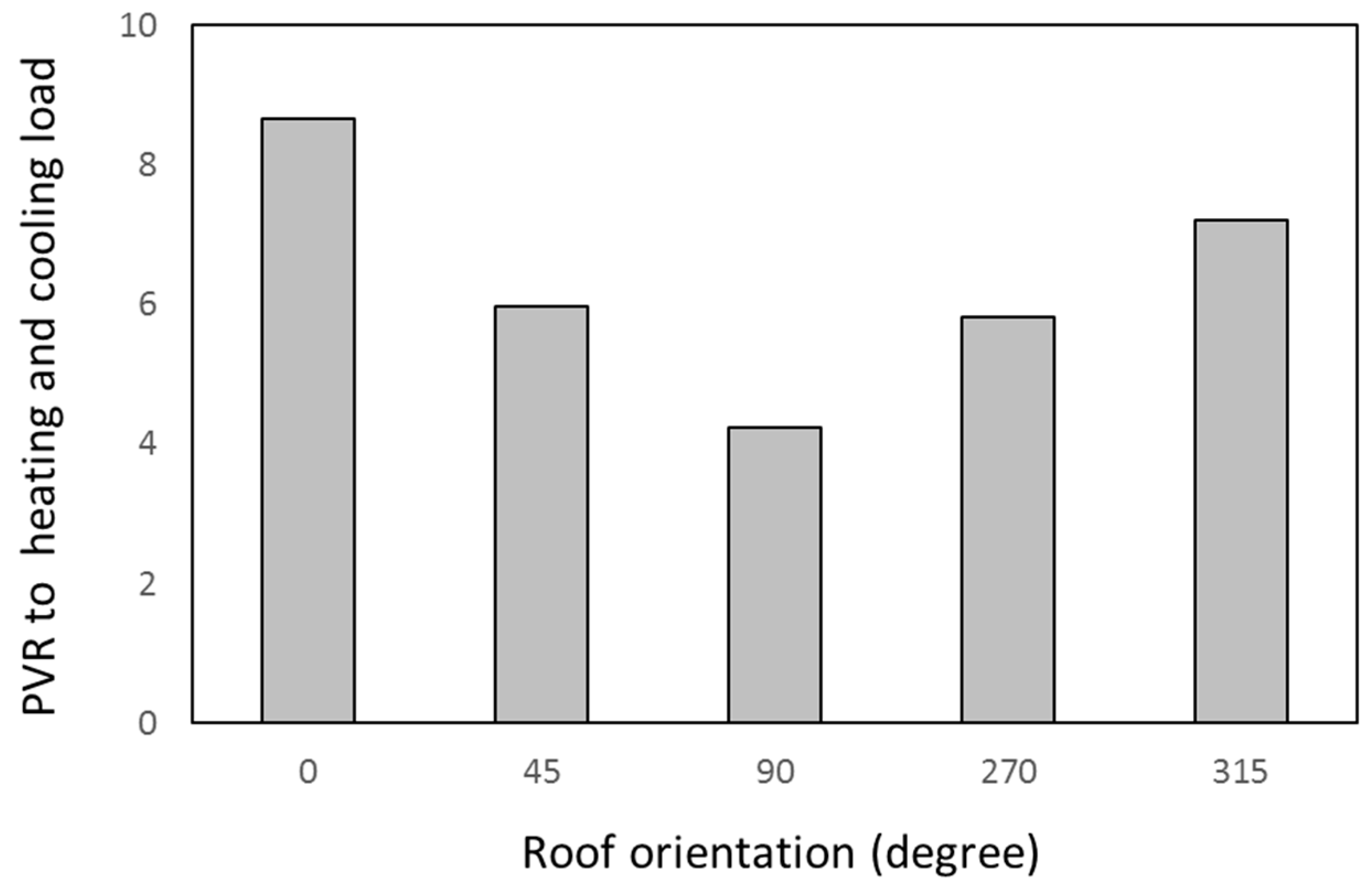
NPV. The energy produced by the rooftop PV panels is affected by two parameters: roof orientation and roof area. The PVSYST and ACCURATE packages were used to estimate the
PVR at different roof orientations and the results are shown in
Figure 10. It is quite obvious that the northern orientation yields the highest value of PVR due to its highest value of energy production. For the dwelling design adopted in this work,
Figure 10 shows that the smallest value of PVR occurred when the roof is facing east, i.e., the azimuth angle equals 90°. It can be concluded from
Figure 11 that the effect of change in
Qhc due to the PV rooftop installation is negligible compared to the solar electricity produced, which can cover, with surplus, the heating and cooling load of the dwelling.
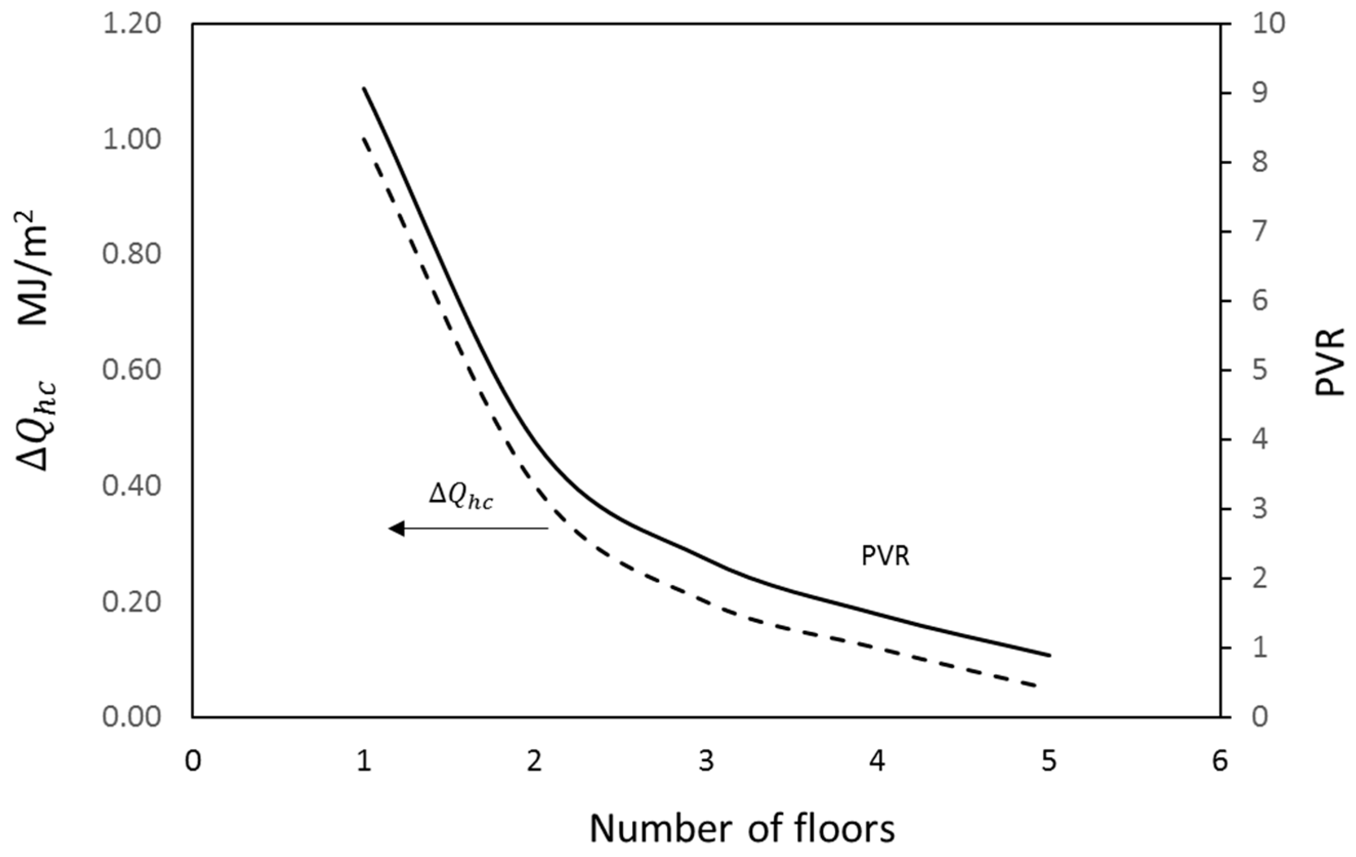
However, this trend of PVR will not stay steady if the number of floors in the dwelling are increased. This was investigated by duplicating the ground floor area in ACCURATE and modelling the heating and cooling load of multi-floor dwellings. The effect of change in the total heating and cooling load (
between the PV roof and the non-PV roof decreases with the number of floors of the dwelling. This can be verified by
Figure 12, which shows that
almost vanishes when the number of floors the dwelling has exceeds 5. The results show that the PVR ratio drops exponentially with an increase in the number of floors in the dwelling. It is clear that the energy produced by the rooftop PV system will not cover the
Qhc if the number of levels in the dwelling exceeds 4. This result can provide a guideline for the limit of the rooftop PV system’s size to meet the dwelling’s energy need or the limit of zero energy design in multi-floor dwellings with reference to a PV rooftop system as an energy source to the dwelling.
6. Conclusions
In this paper, the effect of installing rooftop PV panels on the heating and cooling load of a typical dwelling was investigated. Thermal modelling of a gabled roof was developed considering the thermal resistance of different roof components. The thermal model showed that roof/ceiling insulation is the key form of thermal resistance in the model and the heat gain and loss from the roof becomes almost steady when insulation size approaches 4 m2·°C/W. At this insulation size, the model showed that adding extra components to the external surface of the roof has a minor effect on heat gain or heat loss. The thermal model showed that the bare roof surface, roof with a PV panel, and roof with PV/thermal collector roof configurations make a minor difference in the annual thermal performance of the dwelling when the ceiling insulation’s thermal resistance exceeds 4 m2·°C/W. To investigate the effect of shading developed by rooftop PV panels on the dwelling’s energy efficiency, two types of software were used, namely “ACCURATE sustainability” for thermal assessment of dwellings and “PVSYST” for energy production by the PV system. The results of the thermal assessment showed that in some roof orientations, such as the east and west roofs, adding a rooftop system will cause a reduction in the total thermal load of the dwelling. However, the ratio of this reduction is minor and represents only 3% of the total heating and cooling load. Another factor that causes this small reduction in heating and cooling load is that these PV panels cover only one side of the roof, which leaves the opposite side exposed more to variations in ambient conditions.
The other factor that improves the dwelling’s energy efficiency is the solar electricity produced by the PV system. Both factors were integrated into one equation that estimates the value (PVR), which is the ratio of net energy produced by PV system to the energy required to cover the heating and cooling load of the dwelling. The results show that the thermal impact of adding a PV rooftop system to a dwelling is negligible compared to the amount of solar electricity produced by that system, which covers with surplus the heating and cooling load. However, increasing the number of floors of the dwelling will reduce the PVR ratio exponentially, and the PV system output of a dwelling with a number of levels greater than 4 will not be able to cover the increase in the heating and cooling loads.
It was verified that the insensitivity of the annual heating and cooling load to the thermal resistance of rooftop solar systems is only because the total thermal resistance is dominated by roof insulation. In the case of tropical dwelling designs, the results will be more sensitive due to low or no ceiling insulation and the type of rooftop system will have a stronger effect on the heating and cooling load.
Future work will consider the effect of different designs of PV roofs, including PV-integrated roof tiles and solar hot water collectors, on a dwelling’s thermal performance.


